1
f
^
SAFETY NOTICE
in the destgn and manufaclure of thiB product to assure that no
eirfsls on any exposed metal pan*. Internal service operations can expose the
technFcLan to hazardous line vollages and accldanfally caiise these voltages to appear on
exposed metal parts during repa<r or raassambly of product components. To prevent this, work
on these products should only be periormed by those who are Ihoroughly familiar with the
precaullona necessary when working on this type of equipment.
Great care has been taKdn
shock hazard
To prolMl
ihe ui#r,
H
li
their original condition
FHfutrvd that
all
and the following
ancloture parti and iifety [nteriocki be restored 1o
tetti be peHormed t>efore feturning the pfoduci to
the owner after any lervlce oper alton,
Wug th6 AC line cord directly Into a line voltage AC receptacle (do not use an Isolation
transformer for this lest) and turn the product on. Connect the network (as shown below) In
series with aM e^Kposed metat parts and a known earth ground such as a water pipe or conduit,
Uaa an AC VOM of 5,000 ohms per volt or higher senaillvity to measure the voltage drop across
the network. Move the network connection to each exposed metal part (metal chassis, screw
heads, knobs and control shafla, esculcheor^. etc.) and measure the voltage drop across the
network. Reverse the line plug and repeal the measurements. Any reading of i volts RMS or
more Ja excessive and Indicates a potential shock hazard which must be corrected before
returning the product to the user.
von
kZ
SCUE
O
10K
\
MF
.01
CER*niC RF
BYPASS CAP
TEST
CUPS
TEST
PROBE
CONNECTED TO WOIH
URIH GROUND
TO tIPOSED
lETU
PUflTS
7
TABLE OF COimilTS
SECTION
I
^'^^^
COmOLE POWER WIRING
GENERAL
A BRIEF DEXCRIPT1DH AND SOME ILLUSTMTIONS
OF THE FOLLOWING MODEL ORGANS AND TONE
-
CABINHS
Motor Cifcuiti (Figure
1
Run Switches [Figure
2-15
)
2-16
2)
2-16
SidePenellFigure3&41
PAGE
ORGANS
MANUALS
ft
PEDALS
Menual Assembly (Figuf a
AB
A,
Mpdfli*
BC, BV, BCV. B-2
Modal BA
&
(Roll Pliytf
G. C-2, 2G,
G-40,
Madef
Modali
& B3
1-1
Models A. AV.
O&DV
CV,
a
1-3
,
.
.
2-1
.
Kay Contact Spring (Figure 2)
2-17
2-17
(Figure 3)
2-18
2-13
A-lOa D-lOO
C'3. RT'3,
1-4
RT-3
MA
ModelE
2-lfl
Manual Ajring
Models
1-5
Model A-20
A40
BCV.
A, AV, B, BA. BC,
DV.
Modall
t
G,
CV. D,
C.
2-ig
RT
GV,
B-2, B-3. C-2. C-3. RT-2, RT-3.
1-5
2-19
A-lOaO-100
Model B-40
1-8
Model
M
Modal C-ZO
1-6
Key
Frequency Chert (Figure 4)
Model C-40
1-7
Pedal Switch Assembly (Figure 5)
20
1-7
Pedal Circuits (figure B thru 12)
Modal
RT
Manual Contacts
MDdelsB-3,
TONE CAfilNHS
Modal
DV, G. GV.
Models B-2, C-2, RT-2
Models A-IDO. D-lOO
MndBl
C.
Manual Chassis
(Concart Modall
&
BA, BC,
1-2
1-3
RT, RT-Z,
B,
1-2
Organ)
C-3G Consolei
HR-iOG Tona Cabinati
E
2-17
Manual Chassis
ModffliC, CV, C-2, C-3,
Modeli
1)
1-1
Modvis
ft
2-19
Senas
2-19
2-20
2-21
1-8
tfi-20
2-22
thru
& D-lOO
2-22A
1-8
Pedal Switch Assembly RT-K2,3
Modall H-40, Hfl'40, K-^O, KR-4.0
1-9
Pedal Circuits
2-22B
Model JR'20
1-9
Pedal Keyboard
2-22D
Model F-40
Modal PH-ZD
M
Modal P-40, Q-40
1-10
Modal PR-40, QR-40
Ml
D
M3
THEORY OF OPERATION
DaacripTion
1-13
PreiBl Keys
1-14
Padaf Toe Piiton^
(Model
E
1-16
1-16
Tremulant
1-17
Percussion
1-17
Tone Generator
1-18
Tofie Cabinati
1-lB
Rotor Tremulant
1-18
119
Power Amplifier
II
-
INSTALLATION. MAINTENANCE
ANO TECHNICAL
a
DV. G. GV,
2-24
RT
B-2, B-3. C-2, C-3, flT-2. RT-3.
2-25
2-25
2-25
2-1
ACOUSTICS
General InilailBlJon
2-1
Reverberation
2-2
TREMULANT
2-27
Models A. AB. BC,
C. D, ft
2-27
RHEOSTAT BOX
2 27
Rhaostet Circuits (Figure
2-2B
thru 8)
2-31
thru
[Figure 2
&
2-32
2-33
3)
Vibrato Switch (Figure 4)
2-34
Scanner (Ftgure 5)
2-34
2-34
M
2-35
Schemetics (FigLre 8
2-4
2-4
.
.
Z-5
.,
Z-5
Block Diagrams
(Rfmsl thmll)
Tliru
2-8
2-37
PERCUSSION
2-37
Operation
REVERBERAT10H
Fluid
2-39
Type
Filling
1)
2-3B
Percussion Cui-Dff
llluilralion (Figure
MAIN GENERATOR (mURE
2-36
thru 9)
Block DiaQraini
1
ft
2-42
2-9
Dry Type
2-11
PR & OR Tone Cabinete
2-12
Initallaiior^of
Tone Cabineti
(Figure 2 thru 6)
Service Suggaitions
Earlier
GBMUTOR
Tone Cabinets
Self Contained Unite
§G
JHuitntionslFiBure
1
thni3t
2-14
2-43
PR & QR
Generator lliuitretioni
2-12
2-41
& Adjustment
91 Fraquancy Ganentor
Generator
2-4G
2}
82 Frequency Generator
D. E.
1
VIBRATO
Modsi
CABLES
Models BC,
2-27
G
ModelE
INSTALLATION « MAINTENANCE
CHORUS
2-2B
Preset Cradle [Figure 16|
Une Box
M
2-24
A-10Q, D-1D0. E
Malchir^g Transformers
Preset Keys
Vibrato Diagram (Figure 1)
INFORMATION
Model
2-23
2-24
A. AV. B, BA, BC. BCV, BV, C. CV.
Modal
1-19
System
Wtring Diegrama
2-23
0-100
Frequency Chen (Figure 13|
Charts (Figure 15)
WodeliRT. RT-Z, RT-3&D-100
Echo Switch
SECTION
ft
2-23
&
Pedal
Pedal Keyboard (Figure 14)
1-15
Console)
RT-2, RT-3
Modal E
Models
Padfii Solo linit
ftevertjeration
HI
Models
PRESET PANELS
-
-
2-44
2-44
2-44
2-44
1
1
PAGE
2-45
ECHO EQUIPMEIIT
(Fiflure
&
1
2-i5
2]
2*7
Modal B & BC
Echo
of
iQUfa 5
Kit (f
&
6)
2-48
2-49
Earphones
SECTION
tfl
LIST
OF ILLUSTRATIOM AND INDEX
Modals
3
1
3-2
e.G
A. B. BC, 0,
Wiring Diagram (Figure 15)
3-2
Schamatic (f igufe 16)
3-3
ModeU'100
Schematic (Figure 30)
Wiring Diagram (Figure 31
3-40
Winng Diagram
Schematic
(Figure 17]
18)
(Fiflura
3-41
3-41
(Figure 13)
3-42
Models DR-20, ER-20, FR-40 (Figure 14)
pL^dels H-40. HR-4D (Figure 15)
3-42
Models H-40. HR-40 (Rgura 16)
3-43
REVERB PREAMPLIFIERS SCHEMATICS
Models DR-20, ER-20 (Figure 17)
3-44
Models DR-20, ER-2G, FR-40 (Figure 18)
3-45
POWER AMPLIFIER SCHEMATIC
TONE CABINETS)
(USED
MODELS H-40,HR-40
IN
3-48
(Figure 19)
Models h-40, HR-40 (Figure
1
9B)
3-47
3-47
PRE'AHPUFIER SCHEMATICS
3-4
Models
B'Z, C-2, RT-2 (Figure 20)
3-5
Models
B-2, 0-2. RT-2 (Figure
3-6
Model C-2G
Efl-20,
FR-20,f -40 (Figure 12)
Model»D'20.F-40,FR-40
3-59
3-60
3-40
(Figure 11)
Models D-20. DR-20, B-40.
3-59
3-4
Model 9V, CV
3-47
20A)
POWER AMPLIFIERS SCHEMATICS
TONE CABINETS)
Wiring Diagram
3-6
(USED
Schematic
3-7
Modal JR-20
(Figure 22)
3-8
Model JR-20
(Figure
22A)
3-49
Model JR-20
(Figure
22B)
3-49
Models 82 & C2
Wiring Diagram (Figure 2D)
3-8
Wiring Diagram iFigure 20A)
3-9
Schematic (Figuie 21
3-10
3-11
Models B-3 4 C-3
Model
DR-2aG,0X-20
2-47
Model A
Winng
TONE CABINETS)
Modefi A-20, A-40, B-40, C-40 (Figure 10)
Models A-20, A-40, B40, 0-40. D-ZO.
Z-*6
ModalE
Eariy
m
Kit
m
Install Kit
PABE
POWER AHPUFIER SCHEMATICS
(USED
Echo Organ
Block Oiiflrams
l^
3-48
PREAMPLIFIERS SCHEMATICS
Models
3-50
B-3. C-3, RT-3 (Figure 24)
POWER AMPLIFIERS SCHEMATICS
TONE CABINETS)
Wiring Diagram (Figure 23)
3-11
(USED
Schematic (Figure 24)
3-12
Models PR-40. aR-40 (Figure 26)
3-50
3-86
Models PR-20 (Figure 28)
3-51
Dl 00
3-66
Schamatic (Figure 33)
Wiring Diagram [Figure 35)
Model E
TONE CABINETS
Models PR-40, QR-40
Models PR-40, DR-40 (Figure 26A)
3-18
Wiring Diagram (Sheet 2}
3-19
Wrring Diagram (Figure 19)
Schematic IBV^BC^
&
3-13
Models PR-40, QR-40 (Figure 27A)
Schamatic
SEEPAGE
3-5
3-54
later units
Q40
Q40
Models P-40.
Models P-40,
RT| (Figure 18)
3-53
Schematic
3-13
Modal RT
3-52
3-67
318
1)
Wiring Diagram (Sheet
IN
3-55
(rfgurs 29)
3-56
Schemetic
3-14
Modal PR 20
3-57
Wiring Diagram (Figure 22)
3-14
Model PR-20 Schamatic
3-5B
Wiring Diagrem (Figure 22A)
3-14
Model RT-2
Schematic (B-2. C-2,
8i
SEE PAGE
(Figure 21
POWER AMPLIFIERS
{USED
HT-2)
3-10
3-16
Model RT-3
Wiring Dfagram (Figure 26A|
SchBmBlic|B-3, C-3,
3-16
{figure 24)
3-12
3-61
00
Schematic (Figure 32)
3-61
Wiring Dragram (Figure 33)
3-62
3-6B
REVERBERATION AMPLIFIERS
(USED
PEDAL SOLO uNrr
3-21
General
A-1
Model D-lOO (Figure 36)
fiLflT'3)
SEE PAGE
CONSOLES)
IN
MODEL
CONSOLES)
IN
3-63
Modal A-100 (Figure 34)
Wiring Diagrams
3-22
(Figure 35)
3-64
Tuning
3-Z3
(Rgure35A)
3-65
Block Diagrams (Figure
1
&
1
B)
3-24
3-25
Modai RT Schematic
IMUBLE LOCATION
3
69
3-69
Trouble Shooting
Model RT-2 Schematic
3-26
Sectionalizmg Trouble
3-75
Tube Voltages
3-Z8
Trouble Shooting Chart
3-BO
Service Suggestions
3-29
Repepr
S
3-82
Oisassembfy of Vibrato Scanner
3-30
Removing Parts
3-31
Parts Us!
Winng Diagrams Pedei Solo Gereraior
(Figure 4,
4B,&4C)
3-31
3-32
SECTION
-
IV
41
ALIGNMENT PROCEDURES
4-1
Preset Panel Tone Selection
Alignment
of Coil
4-1
Assemblies
4-4
Adjustment of Percussion Cut-Otf Control
AMPLIFICATION SYSTEM
Adjustment of Intermittent or Non-flpereiing Keys
,
.
,
-
4-4
Pre-Amplitier Schematici
Modal A
3-35
(Figure 1)
Models A
&
ModelsA^B.
C. D,
(Figure
Made[sAV,
& 3)
Player & G
4 & 5)
B (Figure 2
6V, BCV, CV.
ModaJ
E
&
9)
STAGE DATA AND FINAL TESTING
-
6-1
Detailed Theory of Operation
5-1
Components
5-9
Replacement
SECTION
3-38
7)
[Rgura B
SECTION V
of
3-37
DV & RT
3-3B
(Figure 6)
Model E (Figure
3-36
3-39
VI
-
6-1
PARTS LIST
6-5
B-3, C-3
Unique Parts for Other Models Lilted
In Service
Manual
Tone Cabinets (PR-40,
etc.)
6'23
6-31
MODELS A & AS:
(IS PRODUCTION JUNE 1935 TO OCTOBER 1938)
CABTNET SIZE:
4fi-l/2" WIDE, A7" HIGH,
FINISH:
AMERICAN WALKUT
MANUALS
38-1/2" DEEP.
SWELL AKD GREAT. 61 PLAYING KEYS EACH,
I
PEDAL
KEYBOARDS:
25-NOTE, RADIATING, DETACHABLE.
9 PRESET KEYS AND 2 SETS OF 9 ADJUSTABLE
HARMONIC DRAWBARS FOR EACH MANUAL; 2 ADJUSTABLE DRA^ARS (16' AND 8') FOR PEDALS
TONAL
CONTROLS:
EXPRESSION!
ONE EXPRESSION PEDAL CONTROLLING SWELL,
GREAT, AND PEDALS.
FEATURES
ONE TONE GENERATOR, ONE ADJUSTABLE
TREMULANT AFFECTING BOTH MANDALS AND
PEDALS EQUALLY.
AC INPUT
APPROX. 3D WATTS, PLUS WATTAGE REQUIRED
BY TONE CABINETS.
HEI6HTI
AS ILLUSTRATED, APPROX,
359 POUNDS.
SERIAL NO, 2501 AND ABOVE USED LARGER WOODWORK CASE DE
SieNATED AS AB.
SEE B SERIES FOR CASE DIMENSIONS AND WEIGHT.
MODEL AB
SAME AS MODEL A BUT ENCLOSED IN LARGER WOODWORK
ONE TONE GENERATOR, ONE ADJUSTABLE TREMULAKI AFFECTING BOTH MANUALS AND PEDALS EQUALLY.
CABINET
WITH PEDAL KEYBOARD AND BENCH:
A9-1/2" DEEP, 46" HIGH.
MODEL A - AB
SIZE:
AS-3/i" WIDE,
MODEL BCt
(IN PRODUCTION DECEMBER 1936 TO NOVEMBER 1942),
SAME AS MODEL AB BUT WITH ONE ADDITIONAL GENERATOR AND APPROPRIATE SWITCHING TO CREATE CHORUS
EFFECT.
FINISH:
WALNUT.
MODEL BV!
(IN PRODUCTION APRIL 1946 TO DECEMBER 1949).
SAME AS MODEL B BUT EQUIPPED WITH HAMMOND VTBRATO PROVIDING THREE DEGREES OF TRUE VIBRATO
AND "OFF" POSITION, EFFECTIVE SIMULTANEOUSLY
ON BOTH MANUALS, TOGETHER WITH VIBRATO CHORUS
USABLE IN THREE DIFFERENT DEGREES AND "OFF".
FINISH:
WALNUT.
MODEL BCVi
(IN PRODUCTION DECEMBER 1949 TO DECEMBER 1954).
SAME AS MODEL BC BUT HAS HAMMOND VIBRATO AND
VIBRATO CHORUS. NONE PRODUCED, CONVERTED BY
VIBRATO KIT ADDED AFTER 1945-
MOOa. B-2
FINISH:
SAME AS MODEL BV BUT WITH CONTROLS WHICH PROVIDE VIBRATO OK EITHER OR BOTH MANUALS. ALSO
ADDITIONAL CONTROL FOR '^NORMAL" OR ''SOFT"
0\^RALL VOLUME.
(IN PRODUCTION DECEMBER 1949 TO DECEMBER 1954J
WALNUT.
MODEL B-3
(IN PRODUCTION JANUARY 1955 TO)
SAME AS MODEL B-2 BUT WITH HAMMOND PERCUSSION
FEATURE
FINISH:
WALNUT -CHERRY.
MANUALS
SWELL AND GREAT. 61 PLAYING KEYS EACH,
PEDAL
KEVBOARDl
TONAL
CONTROLS;.
25-NOTE RADIATING. DETACHABLE.
9 PRESET KEYS AND Z SETS OF 9 ADJUSTABLE HAR2 ADJUSTMONIC DRAWBARS FOR EACH MANITALABLE DRAWBARS (16' AND 6") FOR PEDALS,
EXPRESSION: ONE EXPRESSION PEDAL CONTROLLING SWELL, GREAT
AND PEDALS,
HOME MODELS BC, BV, BCV, B-2, AND B-3
AC INPUT:
APPROXIMATELY 30 TO 50 WATTS, PLUS WATTAGE
QUIRED BY TONE CABINETS.
WEIGHT!
AS ILLUSTRATED, APPROXIMATELY 425 LBS
RE-
l-l
MODEL B-A
(IN PRODUCTIOH JANUAKY 1938 TO DECEMBER 1938),
THIS INSTRUMENT IS TONALLY AND ELECTRICALLY SIMILAR TO THE MODEL BC CONSOLE DESCRIBED OK THE
PRECEDING PAGES.
IN ADDITION TO NORMAL PLAYING IT COULD ALSO
BE PLAYED WITH ROLLS SIMILAR TO A PLAYER PIANO,
FLOOR DrMENSlONS ARE ALSO SIMILAR TO THE BC WITH
A SOMEWHAT HIGHER BACK SECTION TO ACCOMODATE
PNEUMATIC ACTION.
>
CHURCH MODELS
CV,
C-2, C-3, D AND DV
MODEL C
(IN PRODUCTION SEPTEMBER 1939 TO JUNE 1942).
SAME AS MODEL AB BUT WITH DIFFERENT STYLE
WOODWORK.
ONE TONE GENERATOR, ONE ADJUSTABLE TREMULANT AFFECTING BOTH MANUALS AND
PEDALS EQUALLY,
CABTKH"
WITH PEDAL KEYBOARD AND BENCH:
47" DEEP,
HIGH.
SIZE:
W
46-3/4"
WALNUT.
MODEL CV
(IN PRODUCTION SEPTEMBER 1945 TO DECDIBER 1949).
SAME AS MODEL C BUT EQUIPPED WITH HAMMOND VIBRATO, INCLUDING VIBRATO CHORUS*
MODEL C-2
MODEL D:
(IN PRODUCTION JUNE 1939 TO NOVEMBER 1942).
SAME AS MODEL C BUT WITH ONE ADDITIONAL TONE
GENERATOR AND APPROPRIATE SWITCHING TO CREATE
CHORUS EFFECT,
SIMILAR TO MODEL BC-
FINISH;
WALNUT.
MODEL DV:
SAHE AS MODEL D BUT WITH HAMMOND VIBRATO, INCLUDING VIBRATO CHORUS.
SEE BCV.
NONE PRODUCED, KIT ADDED IN FIELD.
MANUALS!
SWELL AND GREAT, 61 PLAYING KEYS EACH.
t.T:DE,
FINISH:
FINISH:
PEDAL
KEYBOARD!
25-NOTE, RADIATING, DETACHABLE,
WALNUT.
(IN PRODUCTION DECEMBER 1949 TO DECEMBER 1954).
SAME AS MODEL CV BUT WITH CONTROLS WHICH PROVIDE VIBRATO ON EITHER OR BOTH MANUALS. ALSO
ADDITIONAL CONTROL FOR "NORMAL" OR "SOFT"
OVERALL VOLUME,
TONAL
CONTROLS!
9 PRESET KEYS AND 2 SETS OF 9 ADJUSTABLE HARMONIC
DRAWBARS FOR FACH MANUAL; 2 ADJUSTABLE DRAWBARS
C16' AND 3') FOR PEDALS.
EXPRESSlONiONE EXPRESSION PEDAL CONTROLLING SWELL, GREAT,
AND PEDALS,
FINISH
WALNUT
AC INPUTl
APPROXIMATELY AO TO 60 WATTS, PLUS WATTAGE
QUIRED BY TONE CABINETS.
MODEL C-3
(IN PRODUCTION JANUARY 1955 TO)
SAME AS MODEL C-2 BUT WITH HAMMOND PERCUSSION
FEATURE.
WEIGKTs
AS ILLUSTRATED, APPROXIMATELY 450 LBS.
FTNISH:
1-2
C,
HOME MODEL B-A
WALNUT - OAK.
LATER VERSION IN BOTH FINISHES
LESS QDATREFOIL.
RE'
U,S- SOVERW^ErjT PURCHASED EaUIPMENT MODEL G CONSOLE AMD TONE CABINET
The Model G consoles and tone cabinets were built for the
Government, and now will be found in use throughout the
United States and foreign countries In chapels of all services, Officers Clubs, or recreation service buildings.
MODEL C-ZG, C-3G CONSOLES AND IIR-40G
These consoles are identical in appearance Co the C-2
and C-3 except that a monitor speaker Is located on the
lower left hand side.
The console is identical to the Model D except for the
decorative woodwork and provision for detachable handles.
The tone cabinet [Model G-iO) contains two amplifiers and
four speakers mounted in a horizontal row and Is electrically similar Co Model fl-40 tone cabinets, but has a reverberation control unit.
Produced from June I9il to NOVEMBER 1944,
The preamplifier in the C-2G Is designed to operate the
lonitor speaker.
In the C-3G the preamplifier is the
saBie as in the C-3.
A small auxiliary amplifier drives
the monitor speaker- In both Models, B+ voltage from
the tone cabinet is required to make the monitor speaker
operative.
The HR-40G is identical to the HR-40 except that it is
equipped with a standard 6 conductor cable which must be
used in conjunction with the C-2G console.
C-2G in production June 1952 to March 1953,
C-3G in production January 1955 to
CONCERT MODEL E
MODEL El
(IN PRODUCTION JULY 1937 TO JULY 19A2-
CABINET
SIZE;
WITH PEDAL KEYBOARD: 57" WIDE, 46-7/8" HIGH,
47-5/8" DEEP.
FIMSHt
WALNUT
MANUALS;
SWELL AND GRliAT, 61 PLAYING KEYS EACH.
PEDAL
KEYBOARD:
32-NOTE, CONCAVE, RADIATING, DETACHABLE, BUILT
TO AGO SPECIFICATIONS.
TONAL
9 PRESET BUTTONS AND 2 SETS OF 9 ADJUSTABLE HARMONIC DRAWBARS FOR EACH MANUAL: FOR PEDALS - 4
NUMBERED AND LABELED TOE PISTONS 2 ADJUSTABLE
DRAls^ARS <16' AND 8") AND GREAT TO PEDAL S'
COUPLER
CONTROLS:
EXPRESSION!
2 EXPRESSION PEDALS, ONE FOR SWELL AND ONE
FOR GREAT AND PEDALS, VISUAL POSITION INDICATORS OF SLIDING ROD TYPE.
FEATURES:
SEPARATE ADJUSTABLE TREMULANTS FOR SWELL AND
GREAT MANUALS, STANDARD MAIN AND CHORUS GENATOR UNITS; ON AND OFF SWITCH FOR CHORUS.
AC INPUT:
APPROXIMATELY 50 WATTS. PLUS WATTAGE REQUIRED
BY TONE CABINETS.
WEIGHT;
AS ILLUSTRATED^ APPROXIMATELY 579 LBS.
1-3
1
-
CONCERT MODELS RT, RT-2, AND RT-3
MODEL RT:
CABINET
WITH PEDAL KEYBOARD;
47-5/8" DEEP.
SIZE:
FINISH
MODETL
{IN PRODUCTION JULY 1949 TO SEPTEMBER 1949)EQUIPPED WITH HAMMOND VIBRATO PROVIDTSG THREE
DEGREES OF TRUE VIBRATO AND AN "OFF" POSITION,
EFFECTIVE SIMULTANEOUSLY ON BOTH MANUALS, TOGETHEE WITH VIBRATO CHORUS USABLE IN THREE
DIFFERENT DEGREES AND "OFF",
(IN PRODUCTION NOVEMBER 1949 TO JANUARY 1955),
SAME AS MODEL RT BUT WITH CONTROLS WHICH PROVIDE VIBRATO ON EITHER OR BOTH MANUALS, ALSO
ADDITIONAL CONTROL FOR "NORMAL" OR "SOFT"
OVERALL VOLUME.
WALNUT-
MODEL RT'3;
(IN PRODUCTION JANUARY 1955 TO).
SAKE AS MODEL RT'-2 BUT WITH HAMMOND PERCUSSION
FEATURE.
1-4
32-NOTE, CONCAVE, RADIATING DETACHABLE^ BUILT
TO AGO SPECIFICATIONS.
HAS PEDAL SOLO SYSTEM WITH SEPARATE VOLUME
CONTROL, PROVIDING FOLLOWING SOLO EFFECTS;
32-FnnT BOURDON, 32-FOOT BOMBARDE, 16-FOOT
SOLO, B-FOOT SOLO. 4-FOOT SOLO, 2 and 1-FOOT
SOLO.
ALSO TABLETS FOR MUTE CONTROL AND
PEDAL ON.
TONAL
CONTROLS;
9 PRESET KEYS AND 2 SETS OF 9 ADJUSTABLE HARMONIC DRAWBARS FOR EACH MANUAL; FOR PEDALS,
TWO ADJUSTABLE DRAWBARS (16' AND 8').
WALNUT.
fiT-2!
WALNUT - OAK,
SWELL AND GREAT, 61 PLAYING KEYS EACH,
PEDAL
KEYBOARDS:
PEDAL SOLO
SYSTEM!
57" WIDE, 46-7/S" HIGH
FINISH:
FINISH:
MANUALS
EXPRESSION'
ONE EXPRESSION PEDAL, CONTROLLING SWELL,
GREAT AND PEDALS.
AC TNPOTa
APPHOKIMATELY 110 TO 130 WATTS, PLUS WATTAGE
REOUIRED BY TONE CABINETS.
WEIGHT;
AS ILLUSTRATED, APPROXIMATELY 525 POUNDS
r
-1\
MODEL
;
CABINET
:
PRODUCTION 1959 TO 1965}. HOME STYLE CONSOLE. SAME AS
SOUND SYSTEM INCLUDING REVERB CONTROL.
BUT WITH
A-100
A-101
A-102
(IN
A-105
(IN PRODUCTION 1962 TO 1975). CHURCH STYLE CONSOLE, SAME AS
WITH BUILT-tN SOUND SYSTEM INCLUDING REVERB CONTROL.
C-3
BUILT-IN
C-3
BUT
MODEL
D-100
:
(IN
PRODUCTION
1963
TO
1969).
SAME AS
RT-3
BUT WITH BUILT— IN SOUND
SYSTEM INCLUDING REVERB CONTROL.
CABINET
FINISH
SIZE
SAME AS RT
:
D-152
D-155
:
OUTPUT
:
WALNUT
OAK
50
WAHS — 3
AMPLIFIERS, 2-12" SPEAKERS, 2-18" SPEAKERS
AC INPUT:
APPROXIMATELY
WEIGHT
AS ILLUSTRATED, APPROXIMATELY 543
1-4 B
:
330
WATTS
LBS.
Mim
MODEL A-20! (IN PRODUCTION OCTOBER 1935 TO
CABINET
SIZE;
27" WIDE,
FINISH
AMERICAN WAINUT
weiGHT:
OUTPUT;
AC INPUT:
JTJLY 1939)
»
HIGH, 15" DEEP
30*'
113 POUNDS
20 WATTS -
1
AMPLIFIER^
2
- 12" SPEAKERS,
APPROXIMATELY 180 WATTS.
THIS SMALL DECORATIVE TONE CABINET IS USED FOH
HOMES, MORTUARIES, AND SMALL CHURCHES, SEATING
NOT OVER 100 PERSONS, WHERE A LIMITED AMOUNT
OF POWER IS REQUIRED,
MODEL A-20 TONE CABINET
HQ3>Q. A-40:
(IN production October 1935 to October i947)
CABINET
SIZE;
26-1/2" WIDE, 28" HIGH, 19" DEEP
FINISH:
BLACK LACQUER.
WEIGHTS
155 POUNDS
OUTPUT!
iO WATTS -
AC INPUT:
APPROXm\rELY 360 WATTS,
2
AMPLIFIERS,
4
- 12" SPEAKERS
A NON-DECORATIVE, DOUBLE -STRENGTH CABINET, DESIGNED FOR USE IN BANKS OF FOUR OR MORE, IN
LARGE INSTALLATIONS WHERE THE CABINETS ARE
CONCEALED.
MODEL A-40 TONE CABINET
1-5
MODEL B-40!
(IN PRODUCTION NOVEMBER 1936 TO DECEMBER 19A7
CABINEJ SIZE: 36" WIDE, 36" HIGH, 28-1/2" DEEP
FIMSH
WEIGHT;
WALNUT STAIN
225 POUNDS
OUTPUT!
f*Q
AC INPUT:
APPROXIMATELY 360 WATTS-
WATTS
-
2
AMPLIFIERS.
4
-
U"
SPEAKERS.
A SEMI "DECORATIVE, DOUBLE -STRENGTH CABINET DE
SIGNED FOR USE IKDlVlDUALLy OR IN GROUPS.
THE B-40 IS FOUND DESIRABLE FOR MANY CHURCHES
FOR LARGE INSTALLATIONS, FOR IT MAY BE
USED APPROPRIATELY IN AUIOST ANY SETTING,
Am
MODEL B^40 TONE CABINET
MODEL C-20!
(IK PRODUCTION 1937 TO MARCH 19^2).
M0DEL CR-20;
(IK PRODUCTION 1939 - 1942) EQUIPPED WITH
REVERBERATION UNIT.
MODEL CX-ZO:
(IN PRODUCTION JANUARY 1939 TO MARCH 1942)
EQUIPPED WITH ROTOR TREMULANT. SEE MODEL
CXR-20 FOR PICTURE OF THIS FEATURE.
MODEL CXR-20!
(IN PRODUCTION NOVEMBER 1939 TO MARCH 1942)
EQUIPPED WITH ROTOR TREMULANT AND REVERBERATION UNIT.
DIMENSIONS:
29" WIDE, 53" HIGH, iB-I/4" DEEP.
FINISH
HATCHED AMERICAN BUTT WALNUT AND ANTIQUE
BRASS HARDWARE,
WEIGHT:
MODEL C-20, CX-2a, AND CXR-20 TONE CABINET
1-6
153 POUNDS
AMPLI?TKR,
OUTPUTS
20 WATTS,
AC INPUT:
APPROXIMATELY 200 WATTS.
1
2
- 12" SPEAKERS
MODEL C-40i
(IN PRODUCTION JimE 1936 TO DECEMBER 1937)
71" HIGH,
27-1/2" DEEP,
CABINET SIZE:
38" WIDE.
FiNISHi
WALNUT STAIN
WEIGHT:
313 POUNDS
OirrPUT:
UO WATTS -
AC INPUT;
APPROXIMATELY 360 WATTS.
2
AMPLIFIERS AND h - 12" SPEAKERS
THE C-iO CABINET HAS A WIDE VARIETY OF APPLICATIONS.
IT IS ESPECIALLY ADAPTED FOR USE IN ENCLOSURES WHERE
THE INDIRECT PROJECTION OF SOUND IS DESIRABLE. VERY
OFTEN THE CEILING AND FLOOR ARE THE ONLY "LIVE" OR
REFLECTING SURFACES AND THIS TYPE CABINET MARES USE
OF THERE,
THE C-AO CABINET IS USED INDIVIDUALLY OR IN CROUPS
OF TWO OR MORE.
MODEL C-40 TONE CABINET
MODEL D-ZO:
(IN PRODUCTION OCTOBER 1937 TO MARCH 1952),
TONALLY IDENTICAL WITH MODEL C-20, THE D-20
FILLS A NEED FOR AN INEXPENSIVE CABINET FOR
USE IN A WIDE VARIETY OF INSTALLATIONS V.TIERE
DECORATIVE QUALITIES ARE A SECONDARY CONSIDERATION.
MODEL DX-20:
(IN PRODUCTION OCTOBER 1938 TO JUNE 1942).
EQUIPPED WITH ROTOR TREMULANT.
MODEL DR-20!
(IN PRODUCTION AUGUST 1939 TO MARCH 1952).
EQUIPPED WITH REVERBERATION UNIT.
MODEL DXR-ZOl
(IN PRODUCTION APRIL 1939 TO JUNE 1945).
EQUIPPED WITH ROTOR TREMULANT AND REVERBERATIOK UNIT.
CABINET SIZE!
28" WIDE, 56" HIGH.
FINISH:
FACE AND SIDES OF AMERICAN VALNUT.
WEIGKT!
149 POUNDS - D-20: 171 POUNDS - DR-20;
178 POUNDS - DXR-20,
16-3/4" DEEP.
OUTPUT:
20 WATTS - 1 AMPLIFIER, 2 - 12" SPFjUCERS
AC INPUT!
APPROXIMATELY 200 WATTS.
1-7
MODEL ER-20;
CABINET
flN PRODUCTION MARCH 19A7 TO DEGEMBEK 1950)
31" WIDE, 38-3/4" HIGH, IB" DEEP,
SIZE:
FINISH:
WEIGHT:
WALmJT,
lii POUNDS.
AMPLIFIER,
OUTPUT:
20 WATTS -
AC IKPUTt
APPROXIMATELY 200 WATTS.
1
2
-
12^'
SPEAKERS
THE ER-20 TONE CABINET IS ELECTRICALLY EQUIVALENT TO
THE DR-ZO TONE CABINET.
HOWEVER, THE WOODWORK IS
DESIGNED FOR USE IN HOMES WHERE A MORE ARTISTIC CABINET IS PREFERRED.
MODEL ER-20 TONE CABINET
ilii
iiiii
MODEL FR-40
^™
PRODUCTION JANUARY 1948 TO DECEMBER 1957)
CABINET SIZE:
32-15/16" WIDE; 39-3/16" HIGH; 28-3/8" DEEP.
FINISH;
WALNUT STAIN
tClGKri
F-40 - 20a LBS.
FR-40 - 228 LBS-
OUTPUT I
40 WATTS -
AC INPLTT:
APPROXIMATELY 300 WATTS.
2
AMPLIFIEHS, 4 - 12" SPEAKERS
THE F-40 REPLACES THE B-iO TONE CABINET- DIMENSIONS OF
THE WOODWORK HAVE BEEN ALTERED SO THAT A REVERBERATION
UNIT MAY BE ACCOMMODATED. WITH THE ADDITION OF THE
RE\'ERBERATION UNIT IT IS DESIGNATED AS FR.-40.
MODEL F-40 AND FR-40 TONE CABINET
1-8
»
MODEL PR-40
MODEL PR-40!
(IN PRODUCTION FEBRUARY 1939)
CABINH" SIZE! 31-1/2" WIDE; 37-1/2" HIGH; 18" DEEP
FINISH:
WALNUT - OAK - CHERRY
WEIGHT!
130 POUNDS
HODfiL aR-40:
MODEL QR-40
EQUIPPED WITH TWO 15" SPEAKERS FOR BASS TONES AND TWO
iZ" SPEAKERS FOR THE TREBLE TONES.
THEY PROVIDE THREE
DIMENSION AMPLIFICATION WHICH CREATES A BEAUTIFUL REVERBERATION EFFECT IN STEREO. THESE CABINETS FEATURE
THE NEW AND IMPROVED HAMMOND REVERBERATION CONTROL FOR
BOTH BASS AND TREBLE TONES. CONVENIENT OUTSIDE CONTROLS
MAKE IT EASY TO CHANGE THE DEGREE OF REVERBERATION FOR
EACH.
(IN PRODUCTION JUKE 1939)
CABINET SIZE! 31" WIDE; 36-5/6" HIGH; 17-1/^" DEEP
WElGHTi
121 POUNDS
AC INPUT:
220 WATTS
OUTPUT:
50 WATTS E.I. A.
THE QR-40 IS ELECTRICALLY SIMILAR TO THE PR-40 BUT WITH
ITS UTILITY TYPE CABItfET IS ONLY USED WHERE APPEARANCE
IS NOT A CONSIDERATION, SUCH AS IN TONE AND REVERBERATION
CHAMBERS.
THE TREBLE DIRECT SPEAKER IS NORMALLY MOUNTED IN THE TOP.
IN AN UNUSUAL INSTALLATION UTTERE THE CEILING IS VERY LOW
OR CABINETS ARE STACKED OR RADIATION IS OTHERWISE RESTRICTED, IT IS POSSIBLE TO MOVE THIS SPEAKER TO THE HOLE PROVIDED IN THE FRONT. THE METAL DIFFUSER IN FRONT OF THE
SPEAKER MUST ALSO BE MOVED, ANT) THE WOODEN COVER MUST BE
ATTACHED UNDER THE TOP TO CLOSE THE HOLE.
I-II
1-12
THEORY OF OPERATION
The console of the Hammond Organ contains the entire tone-producing
mechanism, which is completely electrical in operation. Within it are
produced ail the tones and tone combinations of the organ. The electrical
waves are made audible, as music, by one or more tone cabinets containing
suitable amplifiers and loud speakers. The block diagrams (Figures 13 and
14) show the chief components of the instrument.
Electrical impulses of various frequencies are produced within a unit known
as the "tone generator'\ containing a number of "phonic wheels" or "tone wheels
driven at predetermined speeds by a motor and gear arrangement. Each
phonic wheel is similar to a gear, with high and low spots, or teeth, on its
edge. As the wheel rotates these teeth pass near a permanent magnet, and
the resulting variations in the magnetic field induce a voltage in a coil
wound on the magnet. This small voltage, when suitably filtered, produces
one note of the musical scale, its pitch or frequency depending on the number
of teeth passing the magnet each second,
II
A note of the organ, played on either manual or the pedal keyboard, generally
consists of a fundamental pitch and a nuiiiber of harmonics, or multiples
of the fundamental frequency. The fimdamental and eight harmonics available
on each playing key are individually controllable by means of drawbars and
preset keys or buttons. By suitable adjustment of these controls the player
is enabled to vary the tone colors at will.
The resulting signal passes through the expression or volume control and
through the preamplifier (where vibrato is introduced) to the tone cabinet.
is added electrically and a power amplifier feeds the
signal into loud speakers,
Here reverberation
DESCRIPTION
A Hammond Ofgan
console (Fig, 2} includes two manuals or keyboards: the
lower, or Great, and the upper, or Swell, and a pedal keyboard of 25 keysa 32-key pedalboard and are constructed to A.G.O.
specifications. Various controls have appeared on different models. The operation of these controls is covered in the following paragraphs,
The concert models have
STARTING THE ORGAN
To
start the organ,
hold the "start'' switch (Fig, 1)
approximately eight seconds.
holding it. push the "run" switch to "on" posAfter leaving both switches on for about four
seconds, release the start switch to return to its
in "on" position for
Still
ition.
normal
position.
the console is very cold, or if a frequency regulator is used, it may be necessary to hold the
If
FIGURE
start switch slightly longer.
1
1-13
1-12
THEORY OF OPERATION
The console of the Hammond Organ contains the entire tone-producing
mechanism^ which is completely electrical in operation. Within it are
produced all the tones and tone combinations of the organ. The electrical
waves are made audible, as music, by one or more tone cabinets containing
suitable amplifiers and loud speakers. The block diagrams (Figures 13 and
14) show the chief components of the instrument.
Electrical impulses of various frequencies are produced within a unit known
as the "tone generator", containing a number of "phonic wheels" or "tone wheels
driven at predetermined speeds by a motor and gear arrangement. Each
phonic wheel is similar to a gear, with high and low spots, or teeth, on its
edge. As the wheel rotates these teeth pass near a permanent magnet, and
the resulting variations in the magnetic field induce a voltage in a coil
wound on the magnet. This small voltage, when suitably filtered, produces
one note of the musical scale, its pitch or frequency depending on the number
of teeth passing the magnet each second.
A note of the organ, played on either manual or the pedal keyboard, generally
consists of a fundamental pitch and a number of harmonics, or multiples
of the fundamental frequency. The fundamental and eight harmonics available
on each playing key are individually controllable by means of drawbars and
preset keys or buttons. By suitable adjustment of these controls the player
is enabled to vary the tone colors at will.
The resulting signal passes through the expression or volume control and
through the preamplifier (where vibrato is introduced) to the tone cabinet.
Here reverberation is added electrically and a power amplifier feeds the
signal into loud speakers.
DESCRIPTI ON
A Hammond
Organ console (Fig. 2} includes two manuals or keyboards: the
lower, or Great, and the upper, or Swell, and a pedal keyboard of 25 keys.
a 3Z-key pedalboard and are constructed to A.G. O.
specifications. Various controls have appeared on different models. The operation of these controls is covered in the following paragraphs-
The concert models have
STARTING THE ORGAN
To
start the organ,
hold the '^start" switch (Fig. I)
approximately eight seconds.
holding it, push the "run" switch to "on" posAfter leaving both switches on for about four
seconds, release the start switch to return to its
in ^'on'' position for
Still
ition.
normal position.
the console is very cold, or if a frequency regulator is used, it may be necessary to hold the
start switch slightly longer.
If
FIGURE
1
1-13
THE
CONCERT MODEL
HAMMOND
ORGAN
THE
HOME MODEL
HAMMOND
ORGAN
FIGURE
Z
PRESET KEYS
left end of each manual are twelve keys identical to the playing keys
color. (Fig. 3). These are replaced by twelve nuinbered
except reversed
buttons on the Model E console.
At the
m
When
a preset key is depressed it locks
is released only when another
depressed. The exception to this is
down and
is
the cancel key at the extreme left, which
serves only to release any key which
may be locked down. Only one preset
key is used at one time. If by mistake
two are depressed and locked, they may
be released by means of the cancel key.
Each preset key, with the exception of
the cancel key and the two adjust keys
at the extreme right of the group, makes
available a different tone color which
has been set up on the preset panel located inside the console- These tone
colors are set up at the factory in
FIGURE 3
accordance with a standard design which
has been found to best meet the average organist' s requirements. They may be
changed, if desired, by removing the back of the console and changing the preset
panel connections in accordance with instructions on a card located near the preset panel.
When
1-14
either adjust key is depressed, the organ speaks with whatever tone color is set
up on the harmonic drawbars associBted with that key. The percussion effect on Models
B-3, C-3, RT-3, A-100 & D- 100 is introduced when the upper manual "B' preset key is
depressed (see ''percussion" also).
HARMONIC DRAWBARS
Each console has four sets of harmonic drawbars, two for each manual. Fig4 shows one group of harmonic drawbars, by which the organist is enabled
ure
aTH HARfc*ONtC
6TH HARMONIC
5TK HARMONIC
4TH HARMONIC
3RD HARMONIC
FIGURE
ONE HARMONIC DRAWBAR GROUP
4
to mix the fundamental and any, or all, of eight different harmonics in various
proportions. The third bar from the left controls the fundamental, and each of
the other bars is associated with a separate harmonic. If a drawbar is set all
the way in, tht' harmonic it represents is not present in the mixture.
Each drawbar may be set in eight different positions by the organist in
addition to the sileni position. Each position, as marked on the drawbars
represents a d^ff^Tent degree of intensity of the harmonic it controls. When
drawn out to position 1. the harmonic it represents will be present w^ith
minimum intensity, wh<"n drawn out to position 2. with greater intensity,
and so on up to position S.
,
A
tone color is logged by noting the numerical position of the various
drawbars- For instance, the tone set up on Figure 4 is known as tone
34 630 SZIO. After a tone is so logged it rnay be made available again by
setting the harmonic drawbars to that number.
The drawbars in earlier consoles have distinct intensity positions with
between them. Later consoles are equipped with "continuous
contact" drawbars which move smoothly with no interruption m tone.
-silent spots
HARMONIC DRAWBARS FOR THE PEDALS
In the pedals the harmonic resources have been combined into two drawbars
which may be used separately or in combinations. When the left drawbar is
used emphasis is given to the lower harmonicSi and similarly the higher
harmonics are emphasized when the right drawbar is used. The pedal drawbars are located between the two sets of manual drawbars.
PEDAL TOE PISTONS
-
MODEL E CONSOLE
tour pedal toe pistons are located to
the left of the expression pedals. Numbers one and two of these pistons are
pedal presets. The third is a Great-toPedal coupler, which makes the pedals
speak with whatever 8 foot tone is set
up on the Great manual. The left pedal
drawbar may he used with the coupler
to add 16 foot tone. The fourth piston
connects the pedals to the two pedal
drawbars.
FIGURE
5
Lighted piston indicators are provided on the left aide of the console
just above the Swell manual. Each
timt' a toe piston is depressed, the
proper indicator is automatically
illuminated so Che organist always
knows which toe piston is depressed.
1-15
U
PEDAL SOLO UNIT
A pedaf
solo unit
tones
addition to the usual pedal
in
is
incorporated
solo tones, generated by a
and
all
eight
tilting
-
MODELS
RT. RT-2, RT-3. D-IOO
the concert Models to provide a series of bright pedal solo
accompaniment tones available on other models. The pedal
vacuum tube
oscillator circuit, are controlled
by a volume control knob
stop tablets located at the right end of the Great manual (Fig.
the pedal solo tones on or
The pedal
in
solo unit
is
off
and the others provide various
independent
of the
5).
pitch registers
One
tablet turns
and tone
colors.
efectromagnetic tone generator and can be turned
off
without affecting the remainder of the organ.
NORMAL SOFT VOLUME CONTROL
'
(Models B-2, B-3, C-2. C-3. RT'2. RT-S, A-100, D-100)
This control (Fig. 3} is a tilting tablet which supplements the action of the
expression pedal. In "'soft" position it reduces the volume of the whole
instrument. It is particularly useful when playing in a small room or when
wishes to practice without disturbing others,
the organist
CHO R
S
CQNT ROL
(Models BC. BCV,
D,
DV, E)
On these models an extra generator known as a chorus generator will be
foxind. To use the tones generated by this unit at will, one extra black
drawbar has been added which operates a switch located on the generator.
The drawbar labeled "chorus" is located at the right-hand end of the console.
(Fig.
6)
the organ is played with the chorus drawbar pushed in (the "off'' position)
exactly the same way as though no chorus were included. Pulling
operates
he drawbar out (to the "on" position) instantaneously adds the ensemble or
-lorus t-ffecl to whatever is being played. Actually it adds a series of slightly
sharp and slightly flat tones to the true tones produced by the main generator.
The resulting electrical wave contams a complex series of undulations which
enhance the pleasing effect of many tone qualities, notably string and full
When
it
m
organ combinations.
The chorus control should not be confusi^d with the "vibrato chorus" effect,
described under "vibrato". The two effects are similar musically, but are
produced by completely different means.
EXPRESSION OR SWELL PEDAL
The swell pedal, located in the customary position, is operated by the right
foot and with it the volume of the organ may be controlled over a wide range.
It operates on the two manuals and pedals equally; that is to say. once the
manuals and pedals are balanced, they retain their relative balance over
the entire swell pedal range.
Two expression pedals are provided for the Model E Console. Both are
equipped with adjustable clamps to regulate the tension and the distance
through which they move. Adjustable pedal indicators, operated by wires
from the rheostat box. are located at the extreme right side of the console
above the Swell manual.
ECHO SWITCH
Located above the starting and running switches
on some consoles is the "echo switch" (Fig. 6).
With this switch it is possible to use two tone cabi
nets and have either cabinet or both speak, depending on the position of the switch. Generally
one tone cabinet is placed rather distant from
the console and is called the "echo organ". This
feature can be added to a Hammond Organ by
installation of an "Echo switch kit".
FIGURE
1-16
6
TREMULANT
The tremulant or tremolo is a periodic variation in intensity of all tones
without change in pitch. It is produced by a variable resistance driven by
the motor of the main tone generator, and is controlled by a variable resistor
in shunt. When the tremulant control is turned as far as possible to the left,
the tremulant is entirely off- As it is turned to the right (clockwise) the degree
of tremolo gradually increases until it reaches a maximum at the extreme right
position. The while dot marker on the knob indicates at a glance the degree of
tremolo present. Two tremulant controls are used on the Model E console, one
for each manual. These are controlled by separate levers located on the console.
The tremulant
is
not incorporated in
models having vibrato.
VIBRATO
effect is created by a periodic
raising and lowering of pitch> and thus is fundamentally different from a tremolo, or loudness variation. It is comparable to the effect
produced when a violinist moves his finger
back and forth on a string while playing,
varying the frequency while maintaining
constant volume.
The vibrato
The vibrato mechanism includes an electrical
line, which shifts the phase of all
tones fed into it- A rotating scanner, mounted
on the main tone generator, picks up successive signals from various line sections. These
signals represent various amounts of phase
shift, and the combinai-ion of signals produces
a continuous frequency variation.
time delay
FIGURE
7
When
the ''vibrato chorus" switch (Fig- 7) (Models AV, BV, BCV, CV.
DV, and RT) is pushed to the left, normal vibrato is obtained with the
vibrato switch in positions 1, Z, or 3. When the lever is pushed to the
right a chorus or ensemble effect, combining foundation organ tone with
vibrato tone, is obtained. The center position of this switch is not intended
used.
to be
No harm will result from leaving the switch in this position, but
reduced volume will be obtained.
Models
B-2. B-3, C-2, C-3. RT-2. RT-3.
which makes the vibrato
lilting
A-IOOA 0-100 have
effect available
on
either
tablets [Figure 3) control the vibrato tor the
the degrees of vibrato or vibrato chorus effect.
pedals as well as
The vibrato
for the
is not
the "seleclivevibraio" feature
manual separately or on both together Two
Iv^'O
manuals, while the rotary switch selects
The "Great"
tabiet controls the vibrato for the
Great manual.
present on models having the tremulant
PERCUSSION
The Percussion teaUjre {Models B-3, C3, RT'3, A-100 & D-lOO) is controlled by
four
tilling
tablets (Fig. 8) at the
right Side of
only
when
upper
the manuals. Percussion
available only on the upper
the
'B'
is
manual and
preset key
Is
depressed. The four tablets (from tefl to
select Percussion on of off, normal
right)
or soft
Volume,
second
FIGURE
8
eame drawbar, and conducting
trol tubes
where
its
Of third
fast or
slow Decay, and
Harmonic lone
quality-
Percusaion tones are produced by
borrowing the second or third harmonic signal from the corresponding manuai drawbar, amplifying it,
returning part of the aignal to the
the balan-ce of the signal through push-pull con-
decay characterica are controlled.
signal is then combined with the signal from the manuals
after the vibrato but before the expression control. The control tubes are
keyed through the eighth harmonic key contacts and busbar.
The Percussion
I-I7
TONE GENERATOR
91 different musical frequencies,
includes a tone wheels magnet, and coil
The main tone generator furnishes 82 or
modeL
depending on the console
It
for each frequency. Mounted on top of the generator are tuned filters to
insure purity of the tones,
PREAMPLIFIER
The preamplifier
is
located in the console. Several types have been used
Some obtain their plate voltage from the
cable, while others have a
in the various console models.
power amplifier through the console -to - cabinet
self-contained power supply,
TONE CABINETS
Tone cabinets are made in a number of models differing in size, finishj and
power output. The numbt-rs 20 and 40 in the model designations indicate the
nominal pow^t'r output in watts. Each tone cabinet includes one or two power
aniplifier^ and two or
more speakers.
Cables of special design are used to connect the console to the tone cabinet
or cabinets,
REVERBERATION CONTROL
the letter R within the model designation are equipped
with the Hammond Reverberation Control. This is an electro -rnechanical
device designed to supply reverberation for installations that are accoustically "dead" or have insufficient natural reverberation. A portion of the
musical signal is delayed by passing through fluid-damped coil springs and
with
direct
then
adjustment
Tone cabinets having
combined
the
signal.
By
of the
amount
of
delayed signal the reverberation characteristics of large or small enclosures
be simulated. A tone cabinet having this unit must be handled in accordance with directions on the instruction card in order to avoid damaging the
may
unit or spilling the fluid.
ROTOR TREMULANT
Tone cabinets having the letter X in their model designation contain a drum
rotor inount*^d above the speakers and driven by a small motor. Rotating in
the path of sound from the loud speal^ers, it produces the effect of a periodic
voluzne and pitch variation in all tones of the organ.
A switch for controlling its operation can be mounted on the tone cabinet, or
an additional cable w^ith a switch located at the console may be used.
When
use
1-18
a console having the
of the rotor
tremulant
Hammond
is
not
Vibrato
is
recommended.
connected to this type cabinet;
POWER AMPLIFIER
A- 100
A
the signal
speakers
from
mounted on
the lower shelf of the console. It receives
the Preamplifier and increases it in power to drive the two 12^^
twelve watt amplifier
is
.
D-100
A
fifty watt three channel amplifier (bass with reverberation, treble, treble
with reverberation) together with its independent power supply is located on
the lower shelf of the console. It receives the signal from the preamplifier
and furnishes power to drive the Z-12^' speakers and Z-8^' speakers.
REVERBERATION SYSTEM
A-lOO
amplifier are the reverberation amplifier and reverberation unit
A portion of the output signal of the power amplifier passes through the reverberation unit to the reverberation amplifier and this drives a third IZ" speaker
housed within the console. The degree of reverberation heard can be regulated by
rotating the knob marked "Reverberation Control" shown in Figure 5.
To the
left of the
D-100
To the left of the pedal solo generator is the Hammond Reverberation unit. Signals from the preamplifier are applied to the ^'treble with reverberation" channel
of the power amplifier and are heard from the 8'^ speaker located to the right
of the player.
In operation, an electrical signal from the reverberation drive channel is applied to the driver unit in the reverberation device which then converts the
electrical signal into mechanical energy. This energy is transmitted through
springs to a pickup unit w^here a part of it is converted back to electrical
energy. The remaining portion is reflected back to the driver and again back
to the pickup at a time interval determined by the spring lengths. This transaction continues until the signal energy is reduced to one millionth of its original value. The transfer time from driver to pickup and the reflections within
the systen^ itself produce the reverberation effect.
1-19
SECTION n
ACOUSTICS
IN
-
THE PART THEY PLAY
HAMMOND ORGAN INSTALLATIONS
INSTALLATION S IN
GENERAL
The proper ln?Eallj.tion of a. H^mmund tir^Lin requires the careful observance of
four primary rules:
1.
The 0Tg:m should furnish AMPLE POWER.
2, The sound energy from the orfi^n should be EVENLY DISTRIBUTED.
3, The console and lone cabinets should be so located m relation to each other and
to the audience, choir, soloist, etc., that a
PROPER TONAL BALANCE
is
accomplished.
4.
The organ tone should be
PROPERLY REVERBERATED.
The observance of these rules with due consideration to the particular use for which
the instrument is required will Insure the best possible installation m any type of
enclosure. These rules will be discussed in detail in the following pages.
P OWER
There are so many factors which have a bearing on the amount of power or sound energy
necessary for best musical results in a t^iven enclosure that an accurate formula for
determinins^ the required power in all cases would be too cumbersome for everyday use.
that it is very seldom that too many tone cabinets are specified.
Experience has shown
Therefore> if there is doubt as to the sufficiency of tone cabinets for any Installation
Lt is reasonably safe to double this amount.
This will j:reatW improve the musical
quality of the instrument and elimmate overloading of the speakers. Some of the factors
which have a bearing on the amount of tone cabinet equipment required in any enclosure
are the size and shape of the enclosure, placement of tone cabinets, amount and location of
sound-absorbing materials including persons present in the enclosure. The use for which
the organ is desired also has a bearinfc on requirements; for example^ an organ to be
used primarily to support congregational singing would require more tone cabinets
than one that is to be used mainly for accompaniment of soloists or light entertainment.
The following conditions in an enclosure, therefore, usually indicate that more than
an average installation may be required:
i. When the area of the boundaries of the enclosure is great in proportion to the volume
of the enclosure- Thus, an enclosure of irregular shape having numerous alcoves, etc.,
would require more lone cabmets than one of cubical shape.
2. When the tone cabinets are located in a position where considerable sound absorption takes place before the music reaches the listener. A poorly designed or constructed organ chamber is an example.
When acoustical correction materials are used on walls or ceiling, when heavy drapes
3are present and carpets are used for floor covering.
4. When seating capacity is high for the size of the enclosure. For practical purposes
an open window is considered as an area of 100 percent absorption of sound. A single
person absorbs about as much sound as four square ieet of open window. Therefore, an
audience of 1,000 people will have the effect on music volume of an open window area of
4.000 square feet as compared with the volume heard when the enclosure is empty. To
offset this absorption, a disproportionately greater amount of tone cabinet equipment
must be used.
DISTRIBUTION
The sound energy from the organ should be distributed as evenly as possible throughout
the enclosure- In order that this may be accomplished, it is important that the sound
be distributed in the auditorium above the listeners and that a large percentage of the
sound reaching the listener is by numerous reflections from the walls and ceiling.
Direct projection as well as direct reflection from the speakers should not reach the
listener. Focusing effects of curved surfaces such as barreled ceilings often cause
difficulty in sound distribution unless the tone cabinet is so located as to reduce the
direct sound energy that reaches these surfaces.
must be remembered that although sound is reflected In a manner similar to light,
the reflecting surlace must be large in relation to the wave length of the sound.
Therefore, a reflecting surface of a given size will reflect sounds above a certain
frequency, while sounds of lower frequency will tie diffracted or spread out. To reflect fully the lower tones of the organ a reflector thousands of square feet in area
ia necessary. This, together with the fact that different materials absorb sounds
of certain frequencies more than others explains why identical tone colors produced
in different enclosures will sound very different to the ear.
It
BALAN CE
The placement of console and tone cabinets should be carefully planned so that the
following conditions are fulfilled:
1.
The organ should sound as loud or slightly louder to the organist at the console
than it does to the audience. This allows the organist to accurately judge the musical effect he is producing and make any necessary corrections before the audience
appreciates the need for them. It also reduces the tendency of playing too loud which is
usually evident when the organist hears the or^an at a lower level than the audience.
2. The organist should hear the organ and the choir with the same relative loudness
that the audience hears them, otherwise a perfect tonal balance between organ and
choir from the organist's point of hearing will result in an unbalanced effect as heard
by the audience. When we refer to the choir we also include instrumental groups or
soloists who may have occasion to perform in conjunction with the organ.
3. The tonal equipment of the organ should be so located that the choir, while singingi
has adequate support from the organ when played at accompaniment volume. They
should noln however, hear the organ so loudly as to have difficulty in singing with itGood lonal balance and ease of performance should result if the average distance
between choir and tone cabinets is about the same distance as between tone cabinets
and organist.
4. The audience should hear the choir and the organ as a balanced ensemble, and
the tone cabinets should be so placed that the choir voices will not te obscured by
the
organ tones.
2-1
REVE KBEIL^TION
Reverberation is the prolongatian or persistence of sound by reflection, what we
usually mean by "echo". It is measurable by the interval of time required for the
sound to decay to inaudibility after the source of the sound has been stopped. It is
present in a varying decree m all enclosures and most types of music are more
pleasing to the ear when accompanied by a certain amount of reverberation. It is
also the most important single factor to be considered in planning an organ installation as proper reverberation makes it easier to attain all of the other requirements
necessary for a perfect installation.
In a Hammond organ installation, the proper amount of reverberation may be secured in three ways:
By the successive reflections of the sound by the boundaries of the auditorium,
1.
2. By the Hammond Reverberation Control.
3. By placm^ the tone cabinets in a chamt>er, the boundaries of which cause the
or^an tones to reverberate before reaching the auditorium.
REVER BERATION IN THE ALTDIT ORIUM
The reverberation that results from the successive reflections of sound back and
forth by the boundaries of the auditorium itself is most desirable from the installation engineer's point of view, (By auditorium we mean any audience room such as a
church or concert hall.)
In a reverberant auditorium less power is necessary and problems of sound distribution are greatly simplified and. therefore, the best possible musical results are
usually obtained as a matter of course. Unfortunately, however, the reverberation
characteristics of an auditoriuna usually are not alterable by the installation engineer,
and he must accept them, good or bad as the case may be.
of one second when a two-thirds capacity audience is present is
usually sufficient if reasonable care is taken in locatmg the organ equipment for proper
distribution and balance although a slightly longer reverberation time is otten desirable. It must be remembered that the reverberation time in any enclosure is greatly
reduced when an audience is present. In jjeneral, the higher the ceiling of the auditorium> the less effect the preseflce of an audience has on the reverberation time;
however, this effect is always considerable. If the natural reverberation in the
auditorium is insufficient for best musical results from the organ, another method
must be used to properly reverberate the organ tones.
A reverberation time
HAMMOND REVERB E ATION CONTROL
The Hammond Reverberation Unit provides an effective means of securing proper
reverberation in all types of installations where the natural reverberation in the
auditorium is insufficient. Experience has shown that best installations in homesT
radio studios, mortuaries, and small churche;^ include a tone cabinet equipped with
reverberation control, it may also be used to improve the effectiveness of the organ
where considerable natural reverberation is present, but where this
natural reverberation is characterized by an objectionable echo occurring after the
organ tones have seemingly ceased. The Hammond Reverberation Unit will not elimi^
nate an echo or reduce the natural reverberation time, but will often make this natural
reverberation more pleasing to the ear by "filling in' that period between the time the
organ tones seem to cease and the echo occurs. The Hammond Reverberation Unit
will not add to the reverberation time in auditoriums already having excessive natural
reverberation. As the reverberation unit is connected to the electrical system of the
organ and provides reverberation at the source of sound rather than after the sound
comes from the speakers, it allows the installation engineer to place the tone cabinets
for best results in balance and distribution without the necessity of compromise for
reverberation considerations. The use of this device also eliminates the necessity
of costly reverberation chambers, and by allowing the tone cabinets to be so located
a.s to minimize sound ener^jy losses, a saving in the amount of necessary power equipment is often effected. A further advantage is that the reverberation time may be
regulated for best musical results after the organ is installed.
With the use of the Hammond Reverberation Unit a good organ installation should
always result if the tonal equipment is placed to give even distribution and proper
tonal balance.
In auditoriums
REVERBERATION CHAMBERS
it is desired to conceal the organ tone cabinets and there is adequate space
available, a properly designed reverberation chamber may be very effective in supplying reverberation for the organ tones. In many cases, however, the space allotted for
use as a reverberation chamber is anything but ideal, and often, because of structural
limitations, little can be done to improve the effectiveness of the chamber other than
When
make minor corrections. The following principles of reverberation chamber design
are given for guidance in properly evaluating the good and bad characteristics of a
given chamber and in making such changes as will improve the effectiveness of the
chamber as much as possible.
to
SIZE
the reverberation time increases as the size of the chamber increases, the chaml>er
should be as large as possible. Experience has shown that practically the only exceptions to this rule are when the shape of the chamber may be improved by reducing
its size or when the tone opening cannot be made large enough in proportion to the size
of the chamber. For best musical results the chamber should be at least 800 cubic feet
in volume. The dimensions of the chamber are in most cases ideal if they are in the
ratio of approximately 2:3:4 1/2, A chamber of equal volume but more cubical In
form would have a longer reverberation time^ while a chamber of less cubical form
would have a shorter reverberation time; however, dimensions in the above ratio usually
are most desirable. Chambers of complex shape or chambers of regular shape whose
greatest dimension is more than three times the least dimension should be avoided ,
As
2-2
CI4ART SHOWING SIZE OF TONE OPENING REQUIRED
FOR REVERBERATION TIME OF ONE SECOND
FOR CHAMBERS WITH DIMENSIONS IN RATIO OF Z 3 4.5
:
:
H
til
b]
<
o
o
O
O
H
o
3
00000
^
iTi
^
r^
CO
VOEUlvlE OF
o
o
o^
o
o
o
o
CHAMBER
FIGURE
o
o
00
00
"1
IN
^
o
o
u-l
O
O
%0
O
O
O
O
CO
f^
CUBIC FEET
1.
CONSTRUCTION AND FINISH
All boundaries of a reverberation chamber should be of exceptionally rigid construction. Concrete or heavy tile is ideal. If the chamber is to be of frame construction
the studs should not be over fourteen inches on centers. Lath should be very securely
nailed and the plaster should be hard and given a smooth finish coat.
TONE OPENINGS
The reverberation time of an organ chamber is greatly influenced by the size of the
For a chamber of given dimensions, the reverberation time is increased
as the area of the tone opening is reduced, A large chamber, therefore, may have a
large tone opening and still furnish sufficient reverberation, whereas a small chamber
might require a very small opening. A chart is shown in Figure 1, giving the area of
tone opening lequired to furnish one second reverberation time when the volume of
the chamber is known. This chart is for chambers with dimensions in the ratio of
2:3:4 1/2 only; however, in practice the areas of tone opening shown are generally
tone opening.
satisfactory.
The
tone opening should be located in the largest wall surface of the
possible, and preferably near the center of the wall area,
chamber
if
INSTALLATION AN D M AINTENANCE
The organ must be connected
regulated-frequency source of the
voltage and frequency specified on the name plate. If the frequency is
not regulated the pitch of the organ will be irregular.
to a
When a console is set up for operation the anchoring must be loosened so that
the generator will float freely on its spring suspension systen]. No damage
if this is not done, but the console "svill sound noisy, and the same
is true if the anchoring is loosened but the console is not level. If the console
is to be moved a long distance the anchoring should be tightened during such
will result
moves.
Several different types of anchoring have been employed and instructions for
loosening and tightening the generator in any particular consoleare given on
the instruction card contained in the bench which accompanied that console.
Each power amplifier has anchoring which should be loosened on installation
and tightned for shipping. If the cabinet has a reverberation unit, it should be
locked before moving the cabinet and the fluid should be removed as instructed
on the card attached to the tone cabinet.
The tone generator is lubricated by putting oil into cups inside the console. It
recoinmended that each cup be filled three-fourths full, {1 tablespoon) once
is
a year» using only the oil
recommended
for this purpose.
2-3
.
CABLES
Each console is shipped from the factory with cables sufficient for an
ordinary installation having a single tone cabinet. It has a 15 foot Z conductor
line cord for connecting to an AC wall outlet, and a 35 foot console -to-cabinet
cable (6 conductor or 5 conductor, depending on the console model) to connect
to the first power amplifier. In case the console is located an unusually long
distance from the tone cabmet, additional 6 or 5 conductor cable must be
ordered. If the console has an echo switch, a b conductor cable of the required
length must be ordered separately to connect it to the echo tone cabinet. (See
"Echo Organ Wiring'', on the following page).
For Installations having two or more tone cabinets, cable suitable in length
must be secured to connect betv-een cabinets. Each power amplifier has a 6
pole input plug and a 5 pole coupling receptacle for connecting additional amplifiers.
TYPES OF CABLES USED
6
Conductor
c
mode ls A. B B A BCj
onsole -to -cabinet cable used only
This is used only between these models
<::>x\
,
,
BCVTBV C,CV D,DV.E,G RT.
,
,
,
of consoles and the first power amplifier, and has a 6 pole plug at one end and
a 6 pole receptacle at the other. It consists of two AC wires, two grid (signal)
wires, a B plus wire to carry plate current from the first power amplifier to
the console preamplifier, and a ground (signal return) conductor^ which is
actually a shield over the B plus wire. This cable is especially designed for
use with the Hammond Or^an and is approved by the Underwriters* Laboratories
for that purpose
,
S^Conductor c onsole -to-cabinet or cabinet-to-cabmet cable. This is identical
conductor cable except that it has no shield and one end has a 5 pole pliig
instead of a 6 pole plug. It has no B plus conductor, the fifth wire being used for
ground. It IS used for carrying power and signal between amplifiers, since a B
plus connection is never needed beyond the first power amplifier; to connect an
echo cabinet, since in this case also no B plus connection is required; and as a
console -to -cabinet cable for models where the console preamplifier has its own
power supply, In case 5 conductor bulk cable is not available, a 5 conductor cable
assen^.bly niay be made from 6 conductor bulk cable, using the shielded wire for
ground and leaving the shield disconnected. NOTE: 5 conductor console -to-cabinet
cable IS used with Models B-2. B-3, C-2, C-3, RT-2. RT-3, A-l 00 8. D-1 00
to the 6
3 Conductor cabinet -to-cabinet cable. This is used for carrying only the
signal between amplifiers, and is used for connecting cabinets when external AC
power vircuits are employed- It is standard 3 conductor indoor telephone cord
5 pole plugs on both ends. A cable may be made up with a number of
plugs along its length in order to connect several cabinets together. This wire
can be secured from your local electrical jobber,
and has
This supplies AC power to the console and has a
Z Conductor li ne cord.
standard attachment plug on one end and a standard attachment receptacle on
the othe r
Z Conductor cabinet power cord^ This is used to furnish AC power to additional
the signal is supplied through a 3 conductor signal cable.
has a standard attachment plug at one end and a 6 pole receptacle at the other.
power amplifiers, when
It
All cables with the exception of the 3 conductor may be ordered in lengths
as shown on current price list, with or without connectors attached- Figure 10
shows how all connectors are wired.
For permanent installations, when the cables are to be installed in conduit,
special "Jones" fittings manufactured by the Cinch Manufacturing Company are
obtainable through your electrical supplier. Those recommended for console
location are;
1-S406-CCE
-P406-WP
1
6
6
prong socket
prong plug with wall plate
For each tone cabinet location:
1-P4C6-CCE
-S406-WP
1
ks
6
prong plug
prong socket with wail plate
BLOCK DIAGRAMS
Figure 1 is a simplified diagram showing how the console is connected to
a single tone cabinet or group of cabinets drawing not over 620 watts input.
This is the maximum AC power which can be supplied through the console
without damaging the console switch or wiring. The name plate on each cabinet
shows its wattage rating.
2-4
r
If the lone cabinet power requirerrjents exceed 6Z0 watts, some of the cabinets
a separate AC source as indicated in figures 2 and 3.
Figure Z is the preferred method, employing a relay to turn on the additional
cabinets. The relay must have a coil of the samke voltage and frequency rating
as the organ, and must have contacts suitable for carrying the an^ount of power
drawn by the additional cabinets. Allen -B radley Bulletin 700 relays are suitable
for this purpose and may be obtained from your electrical supplier.
must be supplied from
When
2
and
AC power is supplied separately to additional cabinets, as in figures
conductor cable is sufficient to carry the signal between cabinets.
the
a
3,
3
DETAILED WIRING DIAGRAMS
Figures 4, 5, and 6 are detailed versions of figure 1 In figure 4 the console is
connected to one tone cabinet having a single amplifier, and figure 5 shows connections to a cabinet with two power amplifiers, connected together by a 5 conductor
.
coupling cable. Additional amplifiers, up to a
be connected as shown in figure 6,
rnaximum
of 620 watts
AC
input,
may
Figure 7 is a detailed diagram of the arrangernent in figure 2. The 3 conductor
cable carries signal to all cabinetSj while each cabinet has its own AC power cord.
In this case the 6 pole input plug in each additional cabinet is used for power input
only, and the signal is fed into the 5 pole coupling receptacle.
A switch may be connected in place of the relay contacts to convert this circuit
to the
arrangement
of figure
3.
ECHO ORGAN WIRING
Some desirable musical effects may be secured by an "echo" tone cabinet installed at a location sonne distance from the main cabinet or cabinets. As indicated
diagram, figure 8, an echo switch on the console controls only the tone
in the block
cabinet signal circuits, and ail cabinets remain energized so that they will sound
instantly when desired. Figure 9 shows the cable connections required.
REVERBERATION EQUIPMENT
Some types of tone cabinets have reverberation units and reverberation
preamplifiers built into them. In this case, see the instruction card attached to
the cabinet for correct cable connections. V/hile there are several different
styles of wiring, it will be found that every cabinet has a 6 pole input plug and a
5 pole output receptacle for connecting additional amplifiers. Some reverberation
preamplifiers employ a special detachable coupling cable, wired as shown at the
bottOiTi of figure 10.
In reverberation-equipped tone cabinets type CR-2D, DR-ZO, ER-ZO, FR-40,
and G-40, reverberation is applied to all organ frequencies. In this case only
one reverberation unit is required for any installation, no rnatter how many tone
cabinets are used. The reverberation unit should be in the cabinet which is connected directly to the console, in order that reverberated signal may be supplied
by it to all other cabinets.
In Multi-channel tone cabmets type JK-20, HR-40, KR-40, PR-ZO, PR -40
and QR-40 a reverberated signal is not available to drive succeeding cabinets. For
this reason an installation using several such cabinets must have a reverberation unit in each cabinet if it is desired that reverberation be present in all
cabinets
.
It is not recommended that Multi -channel cabinets be driven by a reverberated signal from a preceding cabinet because irregularities in the bass response
of the reverberation system may be emphasized by the bass amplifier channel.
In case one of these cabinets is to be used with one or more reverberation cabinets
with the othe
of othe r type s
it should be connected directly to the console
cabinets following it in the usual way,
,
,
Further information on types of reverberation equipment will be found
in
the section dealing with this item.
fit Llf^
COPD
<J
5
OH
6-^OMOUCTOH CABLt
{AC POWER. ^lCf-JA!_^ AND
ONE
Cfl
MOW£ T3NE
CAB* NET 5 .TOTAL IN&
hjOT
OvEH 6^0
rtATTS
B* TO COfJ^OLE)
FIGURE-
I,
BLOCK DIAGRAM OF BASIC TYPE OF INjSTALlATIQN
(for C^TAlLED CONr^CCTlOM^.SEE FKiUPE^ 4.t,4ND 6)
2-5
Il
^^^~
TECHNICAL SECTION
MAIN GENERATOR
-
GENERAL DESCRIPTION
Each Hanrmond Organ console has a main generator
within, it, and in
some cases, depending on the model, a chorus generator. This section
describes the main generator, illustrated below.
Figure
1
The main generator assenibly consists of the generator proper, a shaded
pole induction motor for starting, anon-self-starting synchronous motor
for driving the unit after it is started, and either a tremulant switch
mechanism or a Vibrato Scanner mounted on the synchronous motor. The
entire assembly is mounted on two long steel angles which also provide
the means of mounting the tone generator in the console. The method of
mounting is such as to minimize the transmission of vibration from the
tone generator to the console.
A
drive shaft, resiliently coupled to the synchronous running motor, extends
the entire length of the generator- Twenty-four driving gears, two each of
twelve sizes, are mounted on this shaft, and the drive shaft itself is divided
into several sections connected by flexible couplings. The starting motor
is mounted at the end of this drive shaft, opposite the synchronous motor.
Section 7 describes the starting procedure.
The main generator proper is a long structure in which are mounted 48
rotating assemblies, each consisting of a shaft and two discs known as
tone or phonic wheels. These assernblies are coupled resiliently to the
drive shaft. Each of the driving gears engages fwo bakelite gears
a-^sociated with opposite rotating assemblies (See Figure 2). These
gears rotate freely on the shafts with the tone wheels, and are
coupled to their respective assemblies by a pair of coil springs. There
are 12 sizes of bakelite gears, corresponding to the 12 sizes of driving
gears. Thus 4 of the tone wheel assemblies, each with 2 tone wheels, run
at each of 12 speeds,
"bakelite
Each tone wheel
machined with a
is a steel disc about 2 inches in diameter, accurately
definite number of high and lew points on its edge
(See Figure 3). Each high point on a tone wheel is called a tooth. The
of teeth on each of these tone or phonic wheels, in conjunction
with the speed at which the tone wheel is revolving, determines the frequency of the tone generated.
number
Each driving gear, with its two bakelite gears and four tone wheels, runs
in a separate compartrnent magnetically shielded from the rest by steel
plates which divide the generator into a series of bins.
m
All four tone wheels
any one compartment run at the same speed. The
individual tone wheel shafts are mounted in bearings made of a special
porous bronze and each of these bearings is connected to the oiling system
by a cotton thread from the oil trough. Thus, oil from the trough is carried
by capillary action to all bearings, penetrating thern and lubricating the
actual bearing surface. The drive shaft and both motors are lubricated in
a similar manner. It is very important to use the recommended grade of
oil regularly, as it is essential to the proper operation of the organ that the
generator be well lubricated. If oil of varying grades is used, it is likely
that the generator may be sluggish in starting, and in time the threads may
gum up and prevent the proper flow of oil.
The two spring couplings on the motor shaft, the flexible couplings
between sections of the drive shaft, and the tone wheel spring couplings
contribute to absorbing variations in motor speed. The synchronous
motor does not deliver absolutely steady power, but rather operates
with a se"ries of pulsations, one with each half cycle. If the tone wheels
were rigidly coupled to the motor, this slight irregularity would carry
extra frequencies into each tone wheel. In addition, "hunting" is suppressed
by the resilient couplings and inertia men^bers of the synchronous motor
all
proper.
2-9
Associated with each tone wheel is a magnetized rod about 1/4 of an inch
in diameter and 4 inches in length, with a coil of wire wound near one end
(See Figure 3). The tip of the magnet at the coil end is ground to a sharp
edge and mounted near the edge of the tone wheel. Each time a tooth passes
it causes a change in the magnetic field which induces a small
voltage in the coil, the frequency being determined by the number of teeth
and the wheel speed,
this rod
Sm.aH coils are used on the higher frequency magnets and larger coils
on the lower frequencies. It is found that large pole pieces are needed on
the low frequency magnets to give good frequency output, but is it necessary
to use smaller ones on the high frequencies to prevent excessive iron losses.
Some of the coils have copper rings mounted on them for the purpose of
reducing harmonics. As these are used only on fairly low frequency coils,
the eddy current loss in such a ring is small for the fundamental frequency
of that coil, but high for its harn^onics. This has the effect of reducing
the relative intensities of any harmonics which may be produced by irregularities in the tone wheels. The wheels are cut so to give as nearly
a sine wave as possiblej but the generated voltage seldom reaches that ideal
condition, since even a change in the air gap will change the wave form. The
each magnet, as well as the edge of each tone wheel, is coated with
lacquer to prevent corrosion, for, should oxidation set in, "the change in
tooth shape would introduce irregular frequencies.
tip of
Locations of the various n^agnet and coil assemblies are shown in Figure 4.
They are identified by their frequency numbers, and the broken line between
any two nuinbers indicates that these two frequencies are supplied by one
tone wheel assembly.
Each magnet
is
set at the factory with the set
screw partially loosened,
while observing an output mieter. Experience has shown that the niagnets
seldom need adjustment and that setting them without proper equipment involves
danger of damaging both magnet and w^heel. Therefore it is not recommended that
the service man attempt this adjustment.
As a means
of eliminating any vagrant harmonics that rriay be present, there
are filters consisting of small transformers and condensers associated with
certain frequencies. The transformers have a single tapped winding, and this
tap is grounded, so one side, which is connected to the corresponding magnet
coil through a condenser, forms a resonant circuit for the fundamental
frequency of that
coil.
This tends to emphasize the fundamental and suppress
hartnonics.
Locations of these transformers are shown
shown in schematics in section 2,
in
Figure
5
and
6.
They are
aliio
These transformers and condensers are mounted on the top of the
generator assembly. The transformers are mounted at an angle, thus
minimizing interference between themi. The cores of the transformers
are made of a special iron, and the number of laminations used is adjusted
to secure the proper inductance. Wires from the magnet coils connect to
the transformers, and wires from the transformers lead to the terminal
strip on the generator.
This terminal strip carries the output frequencies of the generator, which
are arbitrarily numbered from 1 to 91 in order of increasing frequency.
This frequency numbering is continued throughout the instrument. In some
models the frequencies are not in order on the terminal strip, and Figures
5 and 6 indicate the arrangement for different models- Several terminals
at the right end are grounded to the generator frame and serve to ground
the manuals and pedals.
Transformers and condensers are not used below frequency 44, but a
length of resistance wire shunts each generator. Frequencies 44 to 48
have transformers only, while both transformers and condensers are used
for frequencies 49 to 91 except in the case of Model A consoles numbered
below 2179, which do not have condensers for frequencies 49 to 54 inclusive.
Two condenser
values are used - 0. 255 mfd for frequencies 49 to 34, and
105 mfd for frequencies 55 to 91. The transformers are all different.
Each transformer is matched to its condenser and any replacements are
supplied as matched pairs by the factory.
0.
2-10
There are several types of generators in use and the foilo\^^ing information
will aid the service technician in identifying the console on which work is
being performed.
91
Frequency Generator
Model
A
serial No.
Model C serial No,
Model D serial No.
2676
1
Model B serial No. 4000
-
10,
1
Model E serial No. 8000
549
3143
8663
Player consoles
1247
1
serial No.
9000
9Z09
The number of tone wheels on the above models is 91, and 5 blank wheels
are used to maintain the balance of the rotating units. There are twelve
wheels with two teeth, one to operate at each of twelve speeds, and
similarly twelve have four teeth, twelve have eight teeth, twelve have
sixteen, twelve have thirty-two, twelve have sixty-four, twelve have one
hundred and twenty-eight and seven have one hundred ninety-two. An
assembly with a two-tooth wheel also has a thirty-two tooth wheel which
generates a frequency four octaves above the other. The four and sixty-four
tooth wheels go together, as do the eight and one hundred twenty-eight tooth
wheels. The twelve sixteen tooth wheels are mounted with seven one hundred
ninety-two tooth wheels and the five blank wheels. In this last group the high
frequency is not four octaves above, but is four octaves less five semi^tones
above the lower.
This arrangement gives a total of 91 frequencies that are connected to
corresponding terminals on the generator, and then to the manuals and
pedal switch. In all cases, as mentioned above, the generator must be
used with corresponding manuals and pedal switches and other types of
generators cannot be substituted.
82 Frequency Generator
Model
A
serial No.
Model B serial No.
2711
Model D serial No. 3144
-
17,
074
Model E serial No. 8664
8739
-
17,
074
Model G serial No. 4101
7349
2677
10,
550
Model C serial No- 1248
17,
074
Player consoles serial No. 9210 only.
In the above consoles, frequencies #1 to 9 have been omitted from the
generator, and only 82 generator terminals are used. Similarly, there are
only 82 tone wheels and magnets in the generator instead of 91- Blank wheels
replace the nine two-tooth tone wheels formerly used to produce frequencies
1
to 9.
This generator change accompanies a wiring revision in the manual and pedal
switches which makes the frequencies from 1 to 9 unnecessary. Generators
having but 82 frequencies are easily identified by a blank space on the terminal
strip at the left of the ground terminals* The first terminal at the left of this
space is terminal #10.
91
Frequency Generator with Cornplex Tone Wheels
Model
BV
-
29737
Model B-2 serial No, 35000
-
40303
Model C-2 serial No. 35001
-
40459
serial No.
17075
Model CV serial No. 17075
302S7
Model RT serial No. 1001
Model RT-2 serial No. 1300
1201
-
Z150
in the above consoles, the original two-tooth wheels in the generator have been
replaced with twelve two-tooth com^^lcx tone wheels, which supply a fundamental tone that is enriched with the odd-number harn:ionics. Both manuals
and pedal switch are wired differently and are therefore not interchangeable
with earlier models.
2-11
91
Frequency Generator with complex tone wheels and narrow cover
Model B-Z serial No. 40304 and above
All
Model C-2 serial No. 40460 and above
Models'
A-100, B-3, C-3
D-100
Model RT-2 serial No.
2151
and above
This generator has twelve complex tone wheels and is identical to the one
above except for the generator cover. Because the output terminals of this
cover are not in order of frequency (See Figure 6) this type of generator is
not interchangeable with the one above.
Model
M
Tone Generator
The generator used in Spinet Models M and M-2 has 86 tone wheels and
from other niodels in several other respects. The twelve complex-tone
wheels are different in shape froin those used in other models, and the
generator-to-rnanual cable connects directly to the filter transformer terminals.
For details, refer to Model M or M-2 service book.
differs
When ordering replacement generators be sure to state model and serial
number of consoles, as generators are not interchangeable.
Note: Consoles have been made equipped with 115 volt 25 or 50 or 60 cycle and
230 volt 50 cycle generators. If the owner is contemplating moving to a
location having a different frequency of current, the complete generator must
be changed^ Where voltage changes only are encountered, step-up or stepdown transformers will be necessary.
r
T
Generator Anchoring
When a console is set up for operation the anchoring rnust be loosened so that
the generator will float freely on its spring suspension system. No damage
will result if this is not done, but the console will sound noisy, and the same
is true if the anchoring is loosened but the console is not level. If the console
is to be moved a long distance the anchoring should be tightened during such
moves.
Several different types of anchoring have been employed and instructions for
loosening and tightening the generator in any particular console are given on
the instruction card contained in the bench which accompained that console.
TOBlE WVJtE-L^
nAtr^iy
O^ntviTt
CO(L
CCLl.
r^fcirtir
ttfcw
BfcHCLat
Oft*¥IHS
GEAR
SECTION OF MAIN GENERATOR
Figure
Z.
CO<L
OUT^T
UAQ^CT
TERMINAL
TO'VE
ONF SlOt OF COIL CftOUWDED
CO>L
2-12
TONE GENtHATOR
WHEEL
GEAR
'
BACK ViEW or MAIN GENERATOR
FRONT VTEW OF MAIN GENERATOR
GENERATOR MAGNET LOCATIONS
Fig^rt
4,
(WiUTtbers shown Art frtqutnty numbers)
FILTER
OUTPUT
FIGURES
1"t.R*^iEHAi,
WODEL^
Fptg^StV
^J^_^^ABE.Pi
GENERftTOR COVER
-MA'.M
ft,&T&Ci6VfcC.C^,t,nv,e,
AMP
RT
OF TflftKSfOHWEa.S
FILTER TRJ^P^^FoRHtfti
MOTO^
Etal
CD1iJH>4S£R5
^
^
-.
^ ^
M
Tr_
«
^
It
4
Afl
flF
ii fi
2J_Sr
H
9
M
M
4^ 2t tZ
M
14
Z
*1
5*.
73
II
fi7
H
fl
T
a*
CJiJTPuT TtffMINAL
ift
J?
.1
4fl
54 34 ta
41
gi
^
<^5
77
[-P
B
S?
11 14
U
7^
^
IC
^?
*-fc
75
rV &3
rs
Si
a
^
fl^
U
flO
B
?d
44
»
S* 17
U
33
1
15
41
FBt^fiUfV NUM&f-ft^
Figures -maim generator cover
MODEL
B-2 5Efi^AL Nu^^flER
hICCfL C £ f^EF^l^L hJUMC^R
^03D4 AhiO A.&OVE
4Q44C Af-Ji) ABOvE
2-13
CHORUS GENERATOR
(Used
in
models BC, D, E, and G
)
The purpose
of the chorus generator is to add a series of slightly
sharp and 'slijjhtly flat tones to the true tones produced by the main
generator. The resulting electrical wave contains a corrtpl^'x senes
of undulations which enhance the pleasing effect of many tone qualities,
notably string and full organ combinations. It should be noted that no
chorus effect is produced on frequencies below 56.
The frequencies covered by the chorus generator are nunibers 56 to
91 inclusive on the main generator. The difference in frequf^ncy between
the main generator and either flat or sharp tone is .8% for frequencies
56 to 67 and .4% for frequencies 68 to 91. It is necessary that a lesser
percentage of frequency difference be present in the higher register
in order to avoid too rapid undulation.
like the main j^enerator, has a drive
shaft with twenty-four brass t^ears. Each gear drives a single asserribly
consisting of two tone y^heels. The drive gears vary as to the number
of teeth, and the tone wheels operate at twenty-four different speeds.
The chorus [generator assen^bly,
This generator has forty -eight tone wheels, each with a separate magnet and pick-up coil. Of these tone wheels, twenty-four are single and
twenty-four are double (see Figure 1). The double tone wheels consist
of two discs wilh different nurribers of teeth mounted on one brass hub.
The single wheels are electrically connected in pairs, each pair being
BO connected as to have the sarne effect as one double wheel.
Fijjure Z is a complete wiring diagram for connections between main
and chorus j^enerators, and Figure 3 is a back view of the chorus
generator indicating the frequency number of each magnet.
<z<Z'a.
^<z<z<z
r^<z<>^<4.o^<z ^'a.<z<z r^<a<z<z
^^
NOTE: NUMBERS SHOWN ON FILTER TRANSFORMERS
ARE FREQUENCY NUMBERS.
CABLE CONNECTIONS
TO CHORUS GENERATOR
Figure
i.
©@©@©@@©@®©®0
H
>
o
-I
o
SB
CONSOLE POWER WIRING
{Main and Chorus Generators)
Starting and Synchronous Motors
A
shaded pole induction motor
is used for starting the generator and
end of the generator as viewed from the back.
motor will slide endwise when current is supplied
pinion on its shaft with a gear on the generator driving
is located at the right
The rotor
of this
and engage
a
shaft, bringing the tone
generator up
to slightly
greater than syn-
chronous speed.
When the organ is started, the starting switch is turned on and held
for about 8 seconds while the starting motor brings the system up to
speed. The "run" switch is then turned on. This switch simultaneously
connects the synchronous motor and introduces a resistor in series
with the starting motor (Figure l), thus reducing its driving power.
With a braking action of the synchronous motor and a loss of power
of the starting motor, the system slows to synchronous speed and
the synchronous motor begins to carry the load. A period of about
B seconds should be allowed for this to take place, after which the
starting switch may be released. The starting switch springs back
to the "off" position, and turns off the starting motor, which is
disengaged from the rotating shaft by a springshould be noted that the synchronous motor can supply power only
synchronous speed, Thereforei if for any reason the system fails
to reach synchronous speed it will not continue to run after the starting switch is released. Failure to start properly is usually due to
increased oil viscosity and may be overconne by an increase in starting time.
It
at
As
the schen-iatic diagram (Figure 1) indicates, the "run" switch in its
"off" position shorts out the wirewound resistor attached -o the line
panel. If the "run" switch is defective in its '"off*" position, the generator
will not start because this resistor will be permanently in series with
the starting motor. Before assuming that there is anything amiss with
the motors, short out this resistor and start the generator in the norrnal
manner. If the generator operates satisfactorily, replace the "run" switch
The "run" switch on all consoles is a two-circuit switch, but types of
switches having two different terminal arrangements have been used, as
shown in Figure 2. When replacing a switch, observe the wiring of the
old switch and check the connections of the new switch with an ohmmeter.
Note that black and blue are connected in the "on" position, and yellow
and brown are connected in the "off" position, no rnatter which type of
switch
is
used.
0.
<
Q
WZ
STARTING MOTORS
SYNCHRONOUS MOTORS
I
m<
-J
a
CHORUS
MAIN
o
MAIN
CHORUS
<
ON
ON
A
A
OFF
OFF
-START"
rvVXAA*-
SWITCH
"RUN"
SWITCH
u
<
WIRE WOUND RESISTOR
U5V, LINE, GEN. - ISO OHMS
115V. LINE, 2 GEN. - 125 OHMS
230V. LINE, 1 GEN. - 1000 OHMS
230V. LINE. 2 GEN. 500 OHMS
1
FIGURE
SWITCH AND MOTOR CIRCUITS
I
2-15
BI^CK
BHOWH
B1.UE
flLJ\CK
ON
ON
^
OFF
YELLOW
BHOMfN
TEL-LOW
SWITCH USED IN MODEL
M AND M-Z CONSOLES
EJ^RLY CONSOLES
AND
OF OTHER MODELS
T
OFF
BLUE
SWITCH USED
IN
LATE MODEL
S. C.
B-Z, C-l. ETC.
],N
FIG 2
T»WO TYPES OF BUN' SWITCHES
OGGG GOG GGO
GOO GOO
WIRE WOUND
RESISTOR
"RUN" SWITCH
STARTING MOTOR YELLOW
'HUN" SWITCH
"S TART^'
,
BROWN
"START''
STARTING MOTOR GREY
SYNCHRONOUS MOTOR
BLUE
SYNCHRONOUS MOTOR
1-RED 1-BLACK OR BLUE
PREAMPLIFIER BLUE
SWITCH BLACK
YELLOW
SWITCH BROWN
'RUN" SWITCH
"RUN" SWITCH
PREAMPLIFIER GREY
OR BLUE
I^INE
FIG,
BLACK
LINE CORD BLACK
l^RED, I-BLACK
CORD GREY
3
LINE PANEL (EARLY CONSOLES)
o o o o o o
@ @
WIRE WOUND
ej
RESISTOR
P
BLUE-
STARTING MOTOR
YELLOW
- YELLOW
''START"
SWITCH
fie
PEDAL LIGHT
BLACK
BLACK
PEDAL LIGHT AND HEATER BLACK
1-RED, i-BLACK
"RUN"
-
BLACK OR GREY LINE CORD
FIG,
4
&
HEATER
''START"
SWITCH
BLACK-LINE CORD
OR BLUE
LINE PANEL (LATER CONSOLES
2-16
SWITCH
1-RED, 1-BLACK OR BLUE
BLUE' PREAMPLIFIER
"RUN"
SWITCH-BROWN
STARTING MOTOR BROWN OR GREY
PREAMPLIFIER BLACK OR GREY
SYNCHRONOUS MOTOR
"RUN"
SYNCHRONOUS MOTOR
"RUN" SWITCH
SWITCH
-
BLACK
Manuals
and Pedals
Fipire
1
A TYPICAL MANUAL CHASSIS ASSEMBLY (Model B-2)
For Description
Manual Chassis Assembly
gy, b. DV. G. GV, RT.
-
Controls See Section
of
2,
Models A, AV. B. B A. EC. BCV, BV. C,
lower
The manual chassis assembly, Fig. 1, which includes the upper and
manual made
manuals and the preset panel, has a terminal strip under each
used, to
up of 82 or 91 terminals, depending on the generator being
accommodate the frequencies from the tone generator assembly. Each manual
which operates
has 61 playing keys, 9 preset keys, and 2 adjust keys, each of
points ( See Figure 2).
nine small bronze contact springs with precious metal
When a key is pressed these points make contact with nine busbars extending
contact
length of the manual. The busbars also have precious metal
the entire
surfaces.
The nine contact springs under each key carry the nine harmonics of the
and are
particular note with which they are associated (See Figure 3)
connected by resistance wires to the proper terminals on the termmal
the generator is
strip. Therefore all key contacts are alive whenever
running. See schematic diagram of console in Section 2,
RESISTANCE MIRE
PAUAPnni
ACT
ALLOY
WIfiE
X
KEY CONTACT SPRING
Figure
A CTUATOR
2
FQK Q NE KEY
I
ITH
Ij
HARVDKEC
tTH HAR^T:^
TOP CONTACT
TOP BUSBAFI
r
4TH HAAMONIC
4T4 HARMONErn
I
I
SPRlJ^C
I
I
I
I
JPD HARMONlt;
I
Z«p KARi*ON]C
f
SUB
UNDAr^lENTAL
^ftP
F
I
HARMONfC
SUB rUNDAME^JlAi
BOTTOKf CONTACT SPRlHC
BOTTOM BUSBAR
I
AHRANCEMENT Of MANUAl- CONTACTS
Figure
3
2-17
When a p!ayinp key is pressed, its nine frequencies are impressed on the
nine busbiirs of the manual. As there are no wires connected to the.se busbars, a pretict or adjusi key mu.st be depressed before any circuit can be
completed. Each preset and adjust key has nine contacts exactly like those
These keys have a locking and trip mechanism which
allows only one key to be in operation at one time. The key at the extreme
end of the manual is a cancel key, with no contacts, which releases any
preset or adjust key that happens to be depressed. (Also see Page 15)
of the playing keys.
left
The adjust keys, A# and B, are connected by flexible wires, color-coded for
easy identification, to the corresponding; nine drawbars. The drawbars slide
over nine busses which arc connected to taps on the matching transformer.
These correspond to different intensities of sound as shown by numbers on
the drawbars.
The two
left groups of drawbars are associated with the upper manual, while
groups work in conjunction with the lower manual. In each case
A^ adjust key controls the lelt hand group of drawbars for that manual.
the two right
the
to A inclusive, are wired to flexible leads
terminating at the preset panel in the back of the console, where the
various tone colors are set up by connecting each wire to a screw terminal
corresponding to the desired intensity of the harmonic. These screw
terminals are located on 9 horizontal bars, each representing: a certain
intensity for all wires attached to that bar.
The nine preset keys, from C#
The drawbar busses and the preset panel bars are connected
primary of the matching transformer.
in
parallel to
taps on the
- Models B-2, C-2 and RT-2
vibrato consoles, the individual manuals are the same as
other models but the drawbar assembly is different, having three tilting
tablets ("Vibrato Swell On-Off," "Vibrato Great On-OIf" and 'Volume SoftNormal') at the left of the vibrato switch knob.
Manual Chassis As^^emb ly
In these selective
in
The selective vibrato feature requires that the preset panel and drawbar
assembly be divided and connected to two matching transformers, each
serving one manual. See schematic diagram in Section 2. The Great, or
lower manual, matching transformer also serves the pedal keyboard.
Continuous-contact drawbars are used in later consoles of this type. They
operate more smoothly and require less accuracy of adjustment than the
earlier type having nine definite positions or steps. Each one has two
contacts connected together by a one ohm resistor, so that at least one qi
the contacts touches some bus at all times and there are no *dead spots^
in the drawbar motion. The resistor avoids short-.circuiting adjacent busbars.
Manual Chassis Assembly - Models B-3, C-3, RT-3, A-100 & D-lOO
The above description also applies to these models, but the start and run
switches are relocated to provide room for four tilting tablets which control
the Percussion feature, described in Secclon lO.All manual chassis assemblies are equipped with continuous contact drawbars.
Manual Chassis Assembly - Bfodel E
The appearance of the ijpper> or swell manual, and the lower, or great manual.
is the same as on other models except that numbered pistons are used instead
of preset keys. These pistons operate in exactly the same manner, and produce
the same effects, as do the preset keys on the other models.
The internal wiring
of the
models, but the use
of
manuals
is to a
large extent the
same
as in other
two tremulants requires that the preset panel and
drawbar assembly be divided, and that two matching transformers be used,
each manual t)eing connected to its own matching transformer.
Manual Busbar Shifters
The precious metal contact surfaces of the key contacts and busbars are
not subject to corrosion, and the manuals are sealed to exclude dust as far as
possible. In spite of these precautions an occasional particle of dus! many
lodge on a contact and cause the note to be scratchy, noisy, or silent, and for
this reason a busbar shifting mechanism is provided on each manual to slide
the busbars endwise and thus provide a fresh contact surface. The busbar
shifter for each manual is a slotted stud near the right end of the manual as
viewed from the back of the console [see rear view of console in Section 2
for location).
any note becomes scratchy or silent, it should first be struck 15 or 2l
times in a rapid staccato manner to loosen the dirt. This will usually dislodge the particles and clear the note.
If
In
case this procedure is not effective, the busbar shifter for that manual
may be adjusted by turning the stud about two turns in either direction. Tt
may sometimes be necessary to hold down the offending key while turning
the
2-18
busbar shifter,
in
order
to
wipe the contact clean.
Model A consoles below serial number 995 are not equipped with busbar
shiiters except in cases where the manual chassis and pedal switch have
been rebuilt. Full information on this rebuilding may be obtained from the
Organ Service Department of the Hammond Organ Company.
Manual Wiring
-
Models
A,
AV. B. BA, BC. BCV. BV, C, CV, D, DV, E,
G,
Figure 4. a wiring chart for the playing manuals, will be helpful in tracing
difficulties associated with the generator or manuals. All playing manuals are
wired alike from drawbar 2 to drawbar 8 inclusive, but the wiring of drawbars
1 and 9 varies.
Column "A" shows the wiring of drawbar 1 for consoles above
serial number 17075; column "B" refers to all consoles having 82 note generators; and column "C" is the wiring used in all earlier consoles. Column
*d" shows wiring of drawbar 9 for Model 'A™ consoles below serial number
2500 and Model "BC" console below 5076; column *E ' refers to all later
consoles.
in wiring are designed to match the different type of
generators described in the section covering lone generators, and therefore
the various types are not interchangeable.
These variations
Manual Wiring Models B- 2. B-3, C-2. C-3. RT-2, RT-3, A-100 & D-IOO
The key circuit wiring for these models ts the same as for previous consoles
above serial number 17075, and so columns 'a' and 'e' in figure 4 apply.
-
Manual Wiring - Model M Series
The frequency chart in this section does not apply to these models because
they have fewer keys on each manual and have a slightly different arrangement of harmonics. Full details will be found in the service booklets covering these models-
PEDAL SWITCH ASSEMBLY
Figure
Pedal Switch Assembly
-
5
All Models with 25 Note Pedal Keyboard
The pedal switch {shown in Figure 51 is similar in construction to the manuals
except that only four busbars are included instead of nine. Each of the 25
pedals actuates a double set of contact springs, making eight contacts available for each note. Each note consists of a fundamental and number of
harmonics, no sub-harmonics being used. The pedal contact springs are
connected to terminals by resistance wires similar to those used in the manual
assembly, and a cable connects these terminals through a wiring tube to the
proper terminals on the generator terminal strip.
Four colored wires carry the pedal tones from the busbars to the pedal drawIn some models the wires are connected first to a resistor panel on the
back of the manual assembly. A small choke coil and resistor mounted on the
bars.
manual assembly are wired to the lower drawbar (see Figures 8» 9, 10, 11) and
to filter out any higher harmonics or transients which might be present
serve
in the
lower pedal frequencies.
Early consoles used only seven contacts on each pedal (see Figure 6) and were
wired so that any harmonic would appear on only one pedal drawbar (Figures
8 and 9), Later consoles use all eight contacts (Figure 7) and employ a
system for mixing the 16 ft. and 8 ft, tones (Figures 10 and 11). The harmonic
arrangement of the contacts is also different in these later units.
Figure 13 is a wiring chart for the pedals, showing the frequency numbers
appearing on each pedal contact. The variations in wiring make the pedal
switches match the different types of generators described in the section
covering tone generators, and therefore the various types are not interchangeable.
Specific pedal wiring of any console can be determined by obtaining the serial
number and referring to Figures 8 to 11, Included in these sketches are references to Figure 13 wiring chart«
ONE PEDAL
TOP CONTACT SPRINGS
8TH HARMONIC
6TH HARMONIC
-iTH
STH HARMONIC
HARMONIC
3RD HARMONIC
2ND HARMONIC
FUNDAMENTAL
5
z
NOT CONNECTED
BOTTOM BUSBAR
ARRANGEMENT OF PEDAL CONTACTS
MODEL A CONSOLES SERIAL NOS. To 2499
MODEL B AND BC CONSOLES SERIAL NOS. 4000 To
1
2-20
Figure 6
5075
TOP CONTACT SPRINGS
HARMONIC
lOTH
12THHARMONJC
6TH HARMONIC
8TH HARMONIC
3
£ND HARMONIC
4TH HARMONIC
FUNDAMENTAL
3RD HARMONJC
BOTTOM BUSBAR
ARRANGEMENT OF PEDAL CONTACTS
ALL OTHER CONSOLES WITH 25 PEDALS
Figure
T
2ND P£DAL DRAW&AR
PEDAL DRAWSAff
1ST
n
FILTER
I
i
a. UJ
19
10
<
o
OHMS
I
Z
>
iTt
Z
wmES
TO PEDAL 5WITCH
FIGURES PEDAL CIRCUITS
MODEL A CONSOLES SERIAL NO. TO 2499
MODEL B AND SC CONSOLES SERIAL NO. 4000 TO 507S
I
(for pedal
^m^MG
SEE FfGuRE
ll^OLUMNS
i,4.5,6,7.ft,9)
OS 2013
JNO PEDAL ORAW&A
I5T
^^i
PEDAL DRAWBAR
2
^
UJ
—|—aooHMs
4
AV^V^-'
I
SOHtbriS
I
RESISTOR PANEL
z
o
u
2
O
a:
O
_l
5 2
<
Xo
<
a
a
z
V
-WIRES TO PEDAL SWITCH
FIGURE 9 PEDAL CIRCUITS
MODEL A CONSOLES SERIAL NO. 2500 TO 26T6
MOD£L B AND BC CONSOLES SERIAL NO. 5076 TO I0S49
MODEL
BA(PLAVEft)C0N50LES-ALL
MODEL C CONSOLES SERIAL NO. liOO TO \247
MODEL D CONSOLES SERIAL NO. TO 3143
(FOR PEDAL WIRING SEE FIGURE li, COLUMNS i,4,5.e.&.9.10j0
I
OS 2014
2-21
2N0 PEIWL DRAWBAft
(FOR WFR|^JG SEE fl&JREIi,
WIBES TO
SWITCH
PCD*l.
FIGURE
PEDAL CIRCUITS
\0
MOOFl a consoles SEPIAL NJO. 2677 TO 27JL
MODEL B, 6C,Ar^D by CONSOi.e& 5£R|Al nO, i05iO TO 17074
MODEL C A»4D CV CONSOLES 5£HiAl_ rXJ. i^-l & ^D \>a7A
WOOEL
A(^D DV CONSOLES 5£KIAl «0 H44 TO ^074
WOOEL G CONSOlES-ALL
OS 2015
^^0 PEOAL DPA-vaAH
P£[W.tmAwBAH
ST
BE5ii70R P*MEL
ULTEB
I
WlOE^ TO PF2AI, SWITCM
FIGURE
1
1
PEDAL CIRCUHS
MODEL 0V AND CV CDN&OLES $£fil*L NO ITO'S IQ 30^67
MODEL RT CONSOLES SFRiAl Kl. lOOl TO I50<
MODEL ^-2 ANDC-? CONbO^ES ^E«1AL nO 35QOO AND A&OvE
MODEL 6 iANP C-i CONSOLES SEflhAL MO SfeOOO AND ABOUE
fcJlODeL RT-E CONSOLES &EfllAL KtO tSOCJ AND ABOVE
MODEL BT-3 CO»J*iC._E.^ ^ERlAL NO flOOO AND A&OVE
(FOR PEDAL ^VlRlMA SEt F|<iunE 13, COLUMNS 7,4,fe, a,a,
I,
I0,1l)
OS 2016
_n
FIKST PEDAL DRA i^BAR
SECOND PEDAL DRAWBAR
TO GREAT
MAN. BUS BARS
^
TO PRE-SET PANEL
PEDAL
PEDAL
2
d»|u
z
-J
X
iM
(A
2
O
Z
o
o
iU3
i
i
ISO
82
ta
3S
OHMS
O
H
OHMS
DHMS
HARM,
IJih
HARM
!0'h
OHMS
^
U
O
C
Ifcth
FREQ
NOS.
r
(-WWV-0
HARM
aih
HARM
6ih
HARM.
3
41
5
b
OHMS
flh
HARM.
Znd
HARM-
10
OHMS
^
Jf
^W%A/v-oZ5 H
rvW\^v—^
HARM.
FUND
f
1
_i
1
^
TO INDICATOR
1
^___
.
WIRING OF PEDAL CIRCUITS
MODEL E CONSOLE
Figure
^WW\—O
f
TX
T"
I
2-22
O
3_£
Ird
12
J
r-VWW-03£
f
a::""^
.
J
4
LIGHTS
20
tv
I
Q
SIGNAL
PICKUPS
FOR PEDAL SOLO
MhIFTES
ON BEAR
PED*L
SWITCH
ACTUATOR
PINS
i
4
t
ft
^
^ «
DOWN STOP
f ELT
FIGURE
MODEL
21
RT. RT-2. RT-3 and D-1 00
Pedal Switch Assembly
The pedal switch (shown in Figure 21) is similar in internal construction to the
manuals (Figure 2Z), Each of the 32 pedals actuates a set of contact springs,
making nine contacts available for each note. Each note consists of a fundamental and a number of harmonics, no sub-harmonics being used. The pedal
contact springs are connected to terminals by resistance wires similar to those
used in the manual assembly, and a cable connects these terminals to the proper terminals on the generator terminal strip. Only seven contacts are used
for the mechanical generator notes, the other two contacts are used by the pedal solo unit as explained later in this book.
Four colored wires carry the pedal tones from the busbars to the pedal drawbars. The wires are connected first to a resistor panel on the back of the manual
assembly. A small choke coil and resistor nnounted on the manual assembly are
wired to the lower drawbar (see Figure 23) and serve to filter out any higher
harmonics or transients which might be present in the lower pedal frequencies.
Figure 24 is a wirmg chart for the pedals, showing the frequency numbers appear
ing on each pedal contact.
2-22A
ACTUATOR FOR ONE KEY
TUNING
TOP CONTACT SPRING
TOP BUSBAR
IK
KEYING
FUNDAMENTAL
2ND, 3RD
HARMONIC
2ND HARMONIC
4TH HARMONIC
6TH HARMONIC
8TH HARMONIC
lOTH HARMONIC
BOTTOM CONTACT SPRING
BOTTOM BUSBAR
fr*
ARRANGEMENTS OF PEDAL BUSSES
FIGURE
D-lOO SERIES
22
2ND PEDAL DRAWBAR
PEDAL DRAWBAR
1ST
LiJ
20 0MM5
5
OHMS
RESISTOR
FILTER
I
10 OHMS
AA/WWW-i
z
o
CL
5
<
<o
on
V
WIRES TO PEDAL SWITCH
PEDAL CIRCUITS
FIGURE
2-22B
23
Pedal
No.
Pedal Keyboard
Pedal keys are set at the factory for average tension^ but are adjustable to fit
the requirements of the individual organist. Adjustment is accomplished by removal of the top cover at the back of the pedal keyboard and setting the tension
as desired,
PEDAL
SWITCH
PUSHERS
MJium.
PEDAL
KEYBOARD
TENSION
ADJUSTING
NUTS
PEDAL
COVER
SINGLE
PUSHER
PEDAL
ADJUSTING
NUTS
FIGURE
2-22D
25
Ped 'Switch Assembly
Model RT, RT-2. RT-3, D-lOO
These models have a 32*note pedal switch assembly, and each note has nine
contact springs which touch nine busbars. Colored wires carry the pedal tones
the busbars to the resistor panel and drawbars as shown in Figure 11,
(See paragraph on "Wiring of Pedal Switch' in "Pedal Solo Unit' section of
from
service manual).
Pedal Switch Assembly - Model E
Nine busbars are used in the Model E pedal switch assembly. Figure 12
illustrates the arrangement of these busbars and the nine contact springs of
a typical pedal key. There are 32 pedal keys, and four pedal toe pistons.
These pedal toe pistons, which correspond to the preset pistons of the manuals,
also have nine contact springs touching the same nine busbars and have a
locking arrangement by which only one piston remains in operation at one time.
Frequencies impressed on the busbars, when a pedal is played, are picked
up by the contacts of the pedal piston which is in use, and go from there to
1 or 2 or to the drawbars through piston 4,
the coupler (Piston 3) the upper seven harmonics connect to busbars
manual, while the lower two connect to the lower pedal drawbar
Connections from the pedals to
it to be used with the coupler.
manual are indicated in Figure 12, A low voltage line from the preamplifier heater transformer operates the 2.5 volt pedal preset indicator
lamps through the external contacts on the pedal switch. Several filter chokes
and resistors mounted on the pedal switch are wired in series with leads from
the preset panel through pistons
From
in the great
and permit
the
the lower pedal
harmonics.
Pedal Busbar Shifters
M
consoles (except Model A consoles below serial number
Pedal switches in
995) are equipped with busbar shifters similar to those on the manuals. The
pedal busbar shifter is a slotted stud on the rear surface of the pedal switch^
near the left end as you look in at the back. It should be adjusted as described
under "Manual Busbar Shifters' on a previous page,
Pedal Keyboard
Pedal keys are set at the factory for average tension^ but are adjustable to
Adjustment is accomplished
fit the requirements of the individual organist.
by removal of the top cover at the back of the pedal keyboard and setting the
tension nuts as desired.
SWITCH PUSHER
HINGE SPR
TENSION ADJUSTING NUT
PEDAL KEYBOARD
OS 2043
Figure
14
Preset Panel - Models A, AV, B, BA. BC. BCV, BV, C, CV, D. DV, G,
GV. RT.
The tone signals from the preset keys on both manuals are carried by
color-coded wires to the preset panel in the back of the console.
is a set of nine bars* wired to the taps on the matching
transformer, corresponding to different intensities of sound as shown by
numt>ers stamped on the bars. Each preset wire, carrying a single harmonic,
is fastened under a screw on the bar which represents the desired intensity
of that harmonic. This is equivalent to setting a harmonic drawbar to the
corresponding number.
The preset panel
When
shipped, each organ has its presets set up as shown in the booklet,
"Creating Beautiful Tone Colors with the Harmonic Drawbars," which maybe
obtained free on request. Preset combinations may be changed at will by
removing the console back and following the directions on a card inside. This
card is reproduced below. (Figure 15)
PresetPanel-ModelsB-2.B-3, 0-2,0-3. RT-2,RT-3,A-1
00,
D-IOO&E
In these models the preset panel is divided into two sets of nine bars, each
connected to a separate matching transformer. One set is used for the
swell (upper) manual, and the other for the great (lower) manual and pedals.
The preset panel on Model E is slightly longer than on the other models to
accommodate the two pedal presets.
2-24
Directions for
Making Pre-Set Panel Connections
Tlicrc are 9 color-codtd wuc^s ihrraded through one of the lower holes for t-ath pre-set key. Above each hole an.' 9 biiiclinj; posts arranged
in vertival ordt't. and abtjvc tiic uppermost binding post is j name plate ,spceif>in^ the pre-set key associated with the row of wires below.
lowest hindinir post is that of /ito strength and lorresponds to a }iarmonie contnil pnshed all the way in. 'i'he uppermost bmding
post is of 8 strenplh and corresponds to a hannonic control drawn a
the way out. The bus-bar strii^s for each level are extended to the
left where they arc marked with their appropriate strength numbers.
For example, suppose the comhinatum 006523411 is to be set up on the D# of the
upper manual It will be foiitid helpful, especially wlien setting several combina-
The
tions, to
M.h>ua1
use the following chart: —
Kiv
Brown
Red
Orange Yellow Green
the front edge of each channel of the 9 preset keys and 2 adjust k/tys, two
flat springs are attached, one 5/8" long of rather stiff material, and another
approximately 3/4" long of softer material. The softer long spring is sandwiched on top of the stiff spring, nearest to the key. The cancel key has only
one heavy spring approximately l" long.
On
a preset key is depressed, the longer soft spring is forced downward and
snaps under a tubular rod which is part of the cradle. The cradle is constructed of two lubes approximately 6*^ long and assembled 3/4" apart. One tube
is used as a fulcrum, the entire assembly being mounted perpendicular to the
preset keys, A spring and bumper hold the cradle at a 60^ angle toward the front
of the console.
When
Once a key has been depressed, the soft spring remains under the tube. It is
backed by the short stiff spring to give it sufficient tension to hold the key
down, When the next preset key is depressed, the cradle is forced down and outward, permitting the previously actuated key to come up» but again locking the
one last depressed.
two preset keys are depressed at Dnce> both will lock down. The cancel key
with its long stiff spring is then used and forces the cradle down, causing all
preset keys depressed to return to their normal position. As there is no locking spring on the cancel key, it will immediately return to its normal position,
If
PRESET "cradle'' RETURN SPRING
Earlier instruments had coil springs of various types to perform the function
of returning the cradle assembly to its rest position, and replacement, when
necessary, became rather involved,
durable spring has been devised, and is used on the later instruments.
can also be used for servicing the earlier consoles.
A more
It
is made as follows: If it is determined that a new return spring
necessary, on either manual, the left hand end block of the manual needing
replacement should be removed. The upper or lower manual assembly will
Replacement
is
the
have to be raised to gain access to the wood screws holding this block. After
removal of this block, the end of the cradle assembly will be visible. Also
visible will be the stop felt and bracket assembly. This is a small angular
bracket with a small piece of felt riveted to it, mounted in a vertical position.
Remove and discard this part.
Install the new assembly so that the felt pad Is above the preset cradle, and
the flat spring is below the cradle, as shown in Figure 16. Clamp it in the
center of the range of adjustment provided by the slot. Check all preset keys
for operation, and adjust the position of the new assembly in case any keys do
not operate correctly.
The new manual preset cradle return spring should be ordered under part number
AO-21709-0.
Figure 16
2-26
TREMULANT SWITCH AND CONTROL
MODELS A-BA-BC-C D -G
The tremulant sometimes called treinolo, is a periodic loudness variation,
or change in intensity, which occurs at a constant frequency. It is fundamentally different from the vibrato effect, which is created by a periodic
raising and lowering of pitch.
Hammond Organ the trennulant effect is produced and controled
principally by two components: the trennulant switch and the tremulant
control.
In the
The tremulant switch, mounted on the synchronous motor at the extreme
left end of the tone generator, is in effect a variable resistor with no sliding
or rubbing contacts. It consists of an eccentric, geared to the motor shafts
which advances a laminated bakelite strip so as to alternately make and break
6 contacts in order. Five resistors are connected to these contacts^ ranging
in value from 15,000 to 450,000 ohms, together with a length of copper wire
of very little resistance. At one extreme position of the eccentric all
contacts are broken and the circuit is open. At the other extrenne all
contacts are closed and there is practically no resistance in the circuit.
The tremulant control, a 130,000 ohm ^^ariable resistor mounted on the
manual chassis assembly, is in parallel with the trennulant switch. When
this control is turned to a position of no resistance, the tremulant switch is
shorted out. Conversely, when the control is turned to its maximum
resistance, the movement of the eccentric varies the resistance of the
circuit periodically from
to 130,000 ohnns. This parallel circuit is in
Thereseries with the signal irom the console, ahead of the pre-amplifier
fore, the signal is varied during each revolution of the eccentric by an amount
depending upon the adjustment of the tremulant control.
.
The tremulant system
is not
used in console models having vibrato.
Model E
The tremulant system for Model E organ is the same as that on other models
except that two switches are used. Each switch i5 mounted on one of the two
synchronous nnotors that are a part of the nnain generator and chorus generator
respectively, and each one is connected to one manuaL The switch mounted on
the main generator operates at 400 R.P,M, and is connected to the Great nnanual
The other switch operates at 348 R.P.M. and is connected to the Swell manual.
Two types of tremulant switches have been supplied, namely, the cage type and
the enclosed type. These are mechanically interchangeable, but replacing the
cage type with the enclosed type does require a slight change in the circuit.
In the enclosed type, the condenser shown as C5 in Figure 4 is incorporated
within the metal housing. Therefore! the C5 located in the rheostat box is not
required and the tremulant switch red wire may be attached to ternninal 6,7, or
8.
RHEOSTAT BOX
The rheostat box contains the expression control rheostat and other
components, including some terminals associated with the tremulant system.
Figures to 8 show various models of rheostat boxes and their circuits. The
rheostat box is used only in console nnodels with tremulant and with non1
selective vibrato.
itself is actually a variable resistor with no sliding contacts.
When the expression pedal is advanced a bakelite csltti moves down, opening
in succession a series of 32 contacts^ tipped with precious metal. The contacts
are connected to fixed carbon resistors.
The rheostat
Resistor RZ in figures 2 and 4 forms a constant load on the matching transformer, while R4 and C4 serve to attenuate the higher frequencies. R4 and
C4 were not used in Model A consoles below serial number U3l. The rheoatatj
in series with bass compensating condenser CZ, is across the signal line, so
that when its resistance is least the volume is least. Condenser C5 avoids
excessive tremolo on the lower bass frequencies. It was not originally
installed in Model A consoles below serial number 23U, C3 is a blocking
condenser and R3 is a grid resistor for the first pream^plifier tube.
2-27
MODEL
BELOW
A CONSOLES SERIAL NUMBERED
^311 HAVE RED TREMULANT
SWITCH WIRE CONNECTED TO TERM. #7
AND CONDENSER C^ IS OMITTED
'O
p]
n
>
H
a
H
o
O
r
r
o
>
n
o
3^
REH TREM
CONTROL
RED TREM
SWITCH
PRE-AMP,
RED
BLACK WIRES FROM
CABLE SHIELDS
RHEOSTAT BOX CONNECTLONS
MODtL B-BA-BC-C-D-C
FIGURE
3
MEG. OHM
TREMULANT
CONTROL
-13
-wvx^vw—
C5
C3
vV^r
^^^
1
TREM.
sVircH -oogMFD aMFD
Ri
EXPRESSION PEDAL
RHEOSTAT
TO
PRE-AMPLTFIER
FROM MATCHING TRANSFORMER
CIRCUIT OF RHEOSTAT BOX
MODEL B-BA-BC-C-D^
FIGURE
2-29
MATCH. TRANS.
PREAMP. RED CONNECTS TO
U, 13 or
15
BLACK
K
EXPRESSION PEDAL
RHEOSTAT
^
PREAMP. SHIELD
MATCH. TRANS.
(pROUND)
SHIELD (GROUND)
RHEOSTAT BOX CONNECTIONS
MODELS AV-BV-BCV-CV-DV-GV-RT CONSOLES
FIGURE
MATCHING
TRANSFORMER
INDUCTANCE
COIL
L
36
CONNECTION FOR
INCREASED OUTPUT
PREAMPLIFIER
INPUT
T
EXPRESSION
RHEOSTAT I
CONNECTION FOR
REDUCED OUTPUT
CIRCUIT OF RHEOSTAT BOX
MODELS AV-BV-BCV-CV-DV-GV-RT CONSOLES
FIGURE
2-30
J21_
<&
*
JTl
_lVi_
Jli.
H
^^
03
GREAT MANUAL
or
TREM. SWITCH
i
C.
r.
i PPE-AMP.
Ef
X
EXPRESSION BHEOSTAT
SWELL MANUAL
r
t:XPRE5SiON RHEOSTAT
MATOH TRANS
>
TREM. CDNTR. r
BHEO GROUND
RHEO. GROUND
PRE-AMP.
TftEM, CONTR.
2 MATCH. TRANS.
P? "^
TREM SWITCH r
c
TERM. tl-TREM. SV. ITCH
TERM- I3'PRE-AMP.-RED;"°LI
TERM, #7-TREM. CONTR. -RED
TERM. #9-MATCH. TRANS-Blj^CK
TERM, #10-TREM. CQNTR -BLACK
TERM. *IZ-TREM SWITCh-BLACK
RHEOSTAT BOX CONNECTIONS
MODEL E CONSOLE
FIGURE
I
SWELL TREM- SalTCH
ON CHORUS) GEN
(
SW ELL
TREMULANT
CONTROL
INPUT FROM SWELL MANUAL
MATCHING TRANSFORMER
TO PRE-AMPLIFIER
'
TO PPE-AMPLlFItR
-5
iNf-UT FROM GREAT MANUAL
MATCHING TRANSFORMER
\
I
GREAT
TREMULANT
y CONTROL
Ll-J
tjtttAT
ON
rflE^.S*ITCH
|^^M V^
GEN
ClKGUiT OF BHEOSTAT BOX
|(ODEL E CONSOLE
FIGURE
s
2-31
THE HAMMOND VIBRATO
THE HAMMOND VTBHATO
consoles equipped with vibrato diifer from tremulant models
omission of the tremulant switch, tremulant control, and non-vibrato
preamplifier, and in the addition of the vibrato line box, scanner, vibrato switch,
and vibrato preamplifier. Three degrees of vibrato are available and also a
different decree of chorus or celeste effect with each of the three degrees of
"2" and "3" in their model designation
vibrato. Console models with the suffix
Hammond Organ
in the
have the selective vibrato feature, with tilting control tablets permitting the
player to place the vibrato effect on either manual or both.
PRINCIPLE OF OPERATION
The vibrato effect is created by a periodic raising and lowering of pitch, and
thus is fundamentally different from a tremolo, or loudness variation. It is
comparable to the effect produced when a violinist moves his finger back and
forth on a string while playing, varying the frequency while maintaining constant
volume.
SECTIONS OF VIBRATO LINE
SIGNAL FHOfct
AMPLIFIER
riRST SECTION
Of PREAMPLIFIER
AMPLiFIE*!
I
Fig,
1
-
Signal '0 SECOND
seCTjOH OF PREAMPLIFIER'
FUNDAMENTAL DIAGRAM OF VIBRATO EQUIPMENT.
The Hammond Organ vibrato equipment (see simpiLfied block diagram, Fig. 1
varies the frequency of all tones by continuously shifting their phase. It includes
a phase shift network or electrical time delay line, composed of a number of low
pass filler sections, and a capacity type pickup or scanner, which is motor driven
so that it scans back and forth along the line.
Electrical waves fed into the line are shifted in phase by each line section (the
amount per section being proportional to frequency), so that at any tap on the
line the phase is retarded relative to the previous tap.
the line will thus encounter waves inphase at each successive lap^ and the signal it picks up
The rate at which this phase shift occurs will
sections are scanned each second.
The scanning pick-up traveling along
creasingly retarded
in
will continuously change in phase.
depend on how many
line
Since a cycle is equivalent to 360 electrical degrees, a frequency shift of one
cycle occurs for each 360 electrical degrees scanned per second. For example
if the scanner passes over the line at such a rate that 3600 electrical degrees
are scanned each second, there will be a frequency change of 10 cycles.
the widest vibrato, the whole line is scanned from beginning to end in about
1/14 second, and this rate of change of phase causes about 1-1/2^ decrease in
frequency. Note that the frequency remains constantly 1-1/2% low as long as
the moving pick-up retards the phase at a constant rate.
For
Since the pick-up sweeps from start to end of the line and then back, it increases the frequency by an equal percentage on its return trip, the average
output frequency remaining equal to the input frequency. The exact amount
of frequency shift depends not only on the amount of phase shift in the line but
also on the scanning rate. This rate, however, is constant because the scanner
is driven by the synchronous running motor of the organ.
The degree of vibrato (or amount of frequency shift) may be varied by a
switch (not shown in Fig. 1) which causes the whole line to be scanned for
#3 (wide) vibrato, about half of it for #2, and about one third for #1.
A
vibrato chorus effect^ similar to the effect of two or three slightly out-oftune frequencies mixed together, is obtained when the vibrato output signal
is mijced with a portion of signal without vibrato. For vibrato chorus, part of
the incoming signal appears across the vibrato line and the rest across a
resistor in series with the line. As the vibrato effect is applied to the part
of the signal appearing across the line but not to the part appearing across the
resistor, the combination produces a chorus effect. For normal vibrato, this
resistor is short-circuited.
2-32
In ^selective vibrato
consoles the vibrato effect can be applied
manual separately or
to both at once.
to either
CONSTRUCTION OF COMPONENTS
Figures
2 and 3 show different models of the vibrato line box. Each of the
air core inductance coils is connected with one or more condensers to form
one filter section.
Figure 4 shows the construction of a typical vibrato switch. Some models
diflfer in wiring and number of contacts, but all are similar in mechanical
arrangement.
The scanner (fig. 5) is mounted on the main generator synchronous motor and
driven at 412 revolutions per minute. It is a muLti-pole variable condenser
with 16 sets of stationary plates and a rotor whose plates mesh with the
stationary ones. In figure 5B two sets of plates have been removed to show
the rotor.
Signals coming from the line through the vibrato switch appear on the stationary
plates and are picked up, one at a time, by the rotor. Connection to the rotor is
made by carbon brushes as shown in figure 5A. Two brushes touch the sides of
the contact pin and a third presses on the end, in order to eliminate the possibility
of contact failure.
'
..Htt
"f^P
hD HtXiiUhL
XLJUtlftt
r\o.2
vjbrato
li*^e
box
FIG 3
ViWato
line
Uiio WITH tincuiT i^owm
box
ih f
icvre »
SCHEMATIC DIAGRAMS
6, 7, 8 and 9 show four different vibrato circuits which have been used
models. As the components of different types are generally not
interchangeable, it is important that model and serial number be furnished when
ordering replacement parts-
Figures
in various
Non-Selective Vibrato
Figure 6^ used in all consoles with V in the model designation, has a 25 section
vibrato line. It is wired (to minimize the number of compensated take-off points)
so that the last part of the line is used for #1 vibrato. The vibrato switch has
positions for three degrees of vibrato (VI, V2 and V3) with three ''off'' positions
between them, and there is a separate vibrato chorus switch. A resistor connected
to the "off" side of the chorus switch serves to maintain constant volume tor the
two switch positions. The switch is not intended to be left in its middle position.
this circuit is actually two separate cascaded
amplifiers on one chassis, with the vibrato system connected between them.
The first section drives the vibrato line, and the second section amplifies
the signal picked up by the scanner. The "vibrato off" contact in the vibrato
switch carries non-vibrato signal directly to the second section of the
preamplifier. The complete schematic circuit of a console of this type is
The preamplifier used with
shown
in
Figure
7 of
section
2,
and preamplifier
in
Figure
6 of
section 11.
2-33
'o F f'oR *C H RU S*CO N TACT
O0T*^uT OF
OUTPUT 0^
FiGURE 6-VlBRATo
_itO
i»*
All WODtL AVh
tt, tCVfc tV*
S^STEf/l
Diih
A»^0
HT"
C014^0lE_^
VIBRATO PM*iE iHlFT Ht^E
FiGuHE
W&ML
C 1
7
-
VfcBHATO
^Y^TErvl
CDP4^0lE^ tELQ* i£Wi*L NuMfct^ MTZJ
2-35
OUTPUT
Of
£KW*7
ViBBATO
PH^^
^HlFT
UNE
FiGURt 3 -VIBRATO SYSTEh^
UDQtL B-Z CONiOLt^
MOMI. 02 CONSOLES
Ha^MR
iTjofl TO
SERIAL,
btRiA.L hUbA^tR Ji?za TO
#4
MFOa-TbOPv^
I
VL
^^^OO^ KH^
^tStJ
^€,\0\ T0-*fri5-4
PD^I^OiH^^^ APd CZ
MA Ck
Put u^
ViVtA-TO
^ 1
^1
S
^
^
^
ViBflAtO PHftSF Shift LIhjE
FI6URL SV^BRATO SVSTEM
MDOtLC-l CC+4UC£.S ^£RlAL_ H^JMfrtR AW»4Z
M(xlelA-100
Model D-100
2-36
^si^
4&0^^
^
^
^
^
1-1
Wt
THE HAMMOND ORGAN WITH PERCUSSION.
Percussion tones are available only on the upper manual (with the B adjust key
depressed) of all consoles with the suffix "3 in their model designation. These
consoles, except for the four percussion control tablets in the upper right hand
corner, look and function similar to consoles with the suffix *2 in their model
designation, when the percussion effect is not in use,
1.
THEORY OF OPERATION
The percussion tones are produced by borrowing the 2nd or^ 3rd harmonic signal
from the corresponding drawbar (of the upper manual ''B adjust key' drawbar
it, returning part of it to same. drawbar, and conducting the
balance through push-pull control tubes, which when keyed cause the signal to
away at a pre -deter mined rate.
group), amplifying
fade
2,
GENERAL CIRCUIT OPERATION
(All
Reference
Is
To Figure 24 Section
2)
With percussion tablet "on", upper manual "B adjust key" and an upper manual
playing key pressed, the 2nd or 3rd harmonic signal appearing on an upper
manual busbar is conducted through "B adjust key' drawbar wire to input of
percussion amplifier (terminal H) and amplified by T4 and V5, Besides providing push-pull signal for the control tube V7, the percussion input transformer
T5 has a third winding which feeds the signal back to the 2nd or 3rd harmonic
drawbar through equivalent key circuit resistor R50 and terminal J. Thus the
signal that was borrowed from the 2nd or 3rd harmonic drawbar for the percussion amplifier is replaced.
When
a key is depressed the signal first sounds loudly through the control tube,
transformer T6, a high pass filter, and terminal D to the grid of V4, Immediately condenser C31 in the control tube grid circuit begins to discharge, causing the
signal to fade away. Terminal K (approximately +25 volts) is connected to the
8th harmonic "B adjust key" drawbar wire which is connected to manual busbar.
When an upper manual key is pressed, terminal K is grounded through the tone
generator filters. This virtually grounds the plate of V6 (connected as a diode),
stops conduction, and isolates cathode and control tube grid circuit. The grid
then drifts from approximately +25 volts to about +15 voltSj at a rate determined
by the time required for C31 to discharge through R57 and R58. At the completion of this sequence the percussion signal is blocked. No further percussion
effects occur until all keys of the upper manual are released and control grids
can again rise to ^25 volts. The rate of this rise is fixed by the time required to
charge C31 to +25 volts through R55 and R56,
3.
FOUR PERCUSSION CONTROL TABLETS. CUTOFF CONTROL, AND THEIR
FUNCTIONS,
The Percussion On-Off Tablet when turned "on" does
manual "B adjust key" drawbars,
five things to the signals of
the upper
disconnects the 2nd harmonic drawbar from its signal wire,
disconnects the 3rd harmonic drawbar from its signal wire.
connects the 2nd or 3rd harmonic drawbar signal wire (depending on
position of Harmonic Selector Tablet) to input of percussion amplifier.
(d) It disconnects the 8th harmonic drawbar from its signal wire. This wire
(connected through generator filters to ground when any key is pressed) is connected to terminal K. The 8th harmonic signal is not available on the upper
(a) It
(b) It
(c) It
2-37
manual as long as percussion tablet is "on",
(e) It inserts resistor Rl in series with upper manual matching transformer
(T2) secondary to reduce upper manual organ signal so that lower manual will
musically balance with the combined upper manual organ and percussion signals.
The Preset Percussion Switch is not part of the control tablet assembly or percussion on-off tablet^ but functions as an interlock with it. It is located under the
upper manual "B adjust key"'. This switch insures that the full upper manual signal is restored by shorting out series resistor Rl introduced by the percussion
'on" tablet when any other upper manual preset or adjust key is pressed.
The Volume Tablet in ''soft" position shunts resistor R46 across the percussion
output transformer, reducing percussion signal, and also shorts out upper manual
matching transformer compensating resistor Rl thus restoring upper manual signal strength to provide proper balance between the manuals.
The Decay Tablet in ''fast" position shunts resistor R57 across the slow decay
resistor (R58) reducing time for decay capacitor C31 to discharge and for V7
control grids to reach cut-off. Also to preserve the same effective loudness in
"fast decay" position as in "slow decay the control tube bias is reduced by disconnecting R59 and allowing control tube grids to become more positive which
increases output signal about 50%.
The Harmonic Selector Tablet does three things
ual *'B adjust key" drawbar group:
to the signals of the
upper man-
In ''Second^ Position:
(a)
It
(b)
It
(c)
It
connects the 2nd harmonic signal wire to percussion amplifier input.
connects the 3rd harmonic signal wire to the 3rd harmonic drawbar,
connects the signal from terminal J to 2nd harmonic drawbar.
In ''Third" Position:
(a)
It
(b)
It
(c)
It
connects the 3rd harmonic signal wire to the percussion amplifier input.
connects the 2nd harmonic signal to the 2nd harmonic drawbar.
connects the signal from terminal J to 3rd harmonic drawbar.
The Percussion Cut-off Control which is located on the amplifier should be readjusted as follows whenever control tube V7 is replaced:
Set expression pedal wide open, both volume tablets "normal
percussion "^on
percussion decay "fast", and harmonic selector
in either position. Depress any key in upper half of upper manual and then adjust cut-off control exactly to the point where
signal becomes inaudible.
,
,
2-38
REVERBERATION CONTROL
Reverberation control la an important feature of any Hammond Organ installation.
This device is enjoying wide acceptance because it produces reverberation in variable degrees so the Hammond Organ, when installed in an acoustically "dead"
enclosure, sounds very much like an organ played in a large acoustically "live"
church or auditorium where organ music, enhanced by considerable reverberation
sounds at its beat.
Reverberation is the prolongation of sound by repeated reflections or echoes,
and Is measured by the time required for a sound to become inaudible after
the source of sound has been stopped. It is present in sonie degrees in all
enclosures, and music is more pleasing to the ear when accompanied by some
amount of reverberation. This is particularly true of organ music.
,
Reverberation results from the fact that the longer path traveled by reflected
sound causes a delay in hearing the reflected sound waves. This is easily
realized in the case of sharp staccato sounds and a fairly distant reflecting
surface, as the delayed sound is then heard separately frorn the direct sound
and LS recognized as an echo. When music is played In a large room, howeverj
the sound echoes and re-echoes repeatedly until absorbed by the surroundings.
The Hammond reverberation control is an electro -rnechanical device which
introduces multiple echoes by means of reflections within a network of coil
springs and thereby provides adequate reverberation in locations where the
natural reverberation is not sufficient.
OPERATION OF FLUID TYPE
The
4x3
inches in cross section
fluid type reverberation unit (see figure I), about
4 feet high, is connected to a reverberation preamplifier built into the
(In some inodels of tone cabinets the reverberation preamplifier
separate unit connected to the power amplifier by cables. The entire equipis attached to the organ tone cabinet.
and about
power amplifier.
is a
)
ment
Reverberation is applied to the organ inusic after it leaves the console. Part of
the console signal goes directly to the power amplifier and part goes into the
reverberation channel, after suitable amplification.
unit is converted into mechanical
a dynamic speaker without a cone.
coil springs, which have the
property of conducting sound vibrations much more slowly then the speed of sound
in air. In this way a spring of convenient length can introduce a delay
equivalent to that obtained in a large hall.
The electrical signal fed into the reverberation
energy by a moving coil driver unit, similar to
The mechanical waves are transmitted through
waves
The driver unit, at the top of figure Z, introduces up-and-down vibrations into
the stirrup directly under it. The two enclosed springs under the stirrup hold
in position but permit it to n:iove freely up and down, and the spring at the far
left balances the pull of the others. These three springs are almost entirely
imniersed in dannping fluid, as they act largely as dampers to stabilize the response of the driver and prevent underaired reflections.
it
A
sound wave from the stirrup travels down the open spring at the far right to
the crystal pickup, where an electrical signal is produced and conducted to the
power amplifier. This is the "first reflected signal"', delayed about 1/15 second
from the part of the original signal which went directly to the power amplifier.
The same wave from the stirrup also travels down the second spring from the
le£tj which enters the short damping tube
At the bottom of this spring the
wave is reflected back along the spring, reduced in intensity by the damping
action of the fluid. At the stirrup the horisontal lever transfers the wave to
the right-hand spring, and it goes on to the crystal to produce a "second reflected signal'* about 3/15 second after the direct signal,
Very
energy of each wave is absorbed by the crystal, and the rest
is reflected back along the spring. The "first reflected signal
traverses the
right spring, is transferred by the lever, and goes down the spring to the short
little of the
'
dannping tube
Here it is reflected in reduced intensity, retraces the same path to the crystal,
and produces a "third reflected signal' about 5/15 second after the direct signal.
The "second reflected signal" is similarly repeated, and this process continues
over and over, giving a series of signals about 2/15 second apart, until the
vibration
is
dissipated by fluid friction in the short tube
Just above the short damping tube a "reflecting pin" attached to the spring
causes partial reflection of high frequencies and helps to make the over-all
response more uniform.
The damper
felt
avoids undesirable transverse vibratioih o£ the springs.
A
'
greater amount of fluid in the short tube will cause increased energy loss at
each reflection and thereby reduce the number of audible reflections. Adjusting
the level of fluid in this tube, therefore, changes the reverberation time and
simulates enclosures of different sizes.
2-39
LEVER
UPPER
DRIVING UNIT
VOICE COIL
STIRRUP
LOWER LEVER
CAWPER FELT
1-^-
LOCK PLATE
SPRING
E
REFLECTI^JG PIN
LOCK PLATE
°
LOCKINGLEVER
CONNECTOR RrBSON
TO AMPLIFIER
REVERBERATION UNIT
FIG. 2.
FIG.
1
A
"reverberation selector awitch" in the amplifier circuit following the
crystal can be adjusted to pass more or less of the reflected signal in proportion to the direct signal. While thia does not actually change the reverberation time, it is a convenient way to change the annount of reverberation
instantly. Generally, therefore, the fluid level in the short tube is left constant, at the position recommended on the tone cabinet instruction card, and
the switch is used to select the best amount of reverberation for each
installation.
The photograph of the reverberation unit (Figure 1) shows a reverberation pre
amplifier of the type used in kits for installation in some non -reverberation
lone cabinets. In later reverberation type tone cabinets the power amplifier
is wired so that this preamplifier is unnecessary.
Amplifier circuits associated with the reverberation unit are shown
section containing amplifier diagrams,
in The
INSTALLATION OF FLUID TYPE
In installations of tone cabmets using type F, type G, and type H power amplifiers, only a single reverberation unit is necessary for any installation, regardless of the nunnber of tone cabinets used. The reverberation unit is connected to
the first power arnplifier (the one to which the console cable connects) and the
reverberated signal is supplied from that amplifier to additional cabinets*
An exception occurs
2-40
in the case of type HR-40, KR-40 and JR-20 tone cabinets,
in which no reverberated signal la available for additional cabinets (because of
the separate bass and treble channels). If reverberation is desired on several
H, J, or K series cabinets, each must be equipped with a reverberation unit.
When two or more types of cabinets are used in any installation, it is preierahead of any
able that anv H or K series cabinets be connected to the console
cabinets having type F, type G, or type H amplifiers in order that reverbermay be
ated signals may not enter the bass amplifier channel. Otherwise there
objectionable irregularities in the response of the lower pedal notes.
Further information on the use of reverberation
covering Acoustics.
may
be found
in the section
FILLING AND ADJUSTMENT OF FLUID LEVEL
When installing a reverberation unit or tone cabinet, the damping fluid (furnished in bottles with the unit) should be added with care, following directions
on the tone cabinet instruction card- The level in the three long tubes is not
critical; for best damping it should be near the top, but not high enough to spill
if the unit is moved. Enough fluid is furnished to fill each tube to about one
inch from the top.
The short tube should be filled to exactly 3-1/4 inches from the top, using
the special suction bulb supplied. This amount of fluid gives the best reverberation effect for average conditions.
If acoustic conditions are very unusual, or if an organist has a defintte preference for greater or less reverberation, the level in the short lube may be
set higher or lower. Lower fluid level will give longer reverberation time
and higher fluid level will give shorter time. There is a temperature effect
due to change in viscosity of the fluid (lower temperatures will shorten the
reverberation time and higher temperatures will lengthen it) but no adjustment for this effect is necessary unless the temperature is consistently
below 50^ F or above 95^^ F.
The reverberation selector switches are set at "HT' when leaving the
factory, and should be readjusted on installation to give the most desirable
reverberation effect. If th^re is any uncertainty as to the proper adjustment, it is generally preferable to allow too much reverberation rather
than too
little
.
OPERATIONAL ADJUSTMENTS OF FLUID TYPE
a well known acoustical phenomenon that audibility of some frequencies
emphasized over others in any given enclosure. Range of frequencies affected depends upon the size and type of reflecting surfaces such as walls
and ceilings. Thus if a musical instrument such as an organ is played in an
It is
is
enclosure of almost any size, some frequencies will sound louder in one
portion of the listener area than in another, and conversely some frequencies
will sound weak. This can be effectively demonstrated by playing the organ
in a em.all room with a microphone, then listening to the signal picked up by
the microphone in another room. Variations in loudness will be startling
especially when single frequencies are sounded.
The reverberation unit similarly produces a "response pattern" which tends
emphasize some frequencies over others to a slight degree. This is an
operating phenomenon of the equipn^ent and cannot be eliminated. This room
pattern effect has not proved seriously objectionable because as described
above it stimulates an acoustical effect which is present in some degree
whenever any musical instrument producing a wide range of frequencies ia
played in an enclosure.
to
^
the organ sound excessively loud while others sound weak
be traceable to the reverberation control system. In investigating
this, disconnect the reverberation system by turning the switch on the reverberation preamplifier or amplifier to the "off" position. If notes then
sound at equal loudnes s turn reverberation system on again and make the
following adjustments:
If
some notes on
it
may
,
I.
The two-pole plug, which
is
connected
to
wire carrying signal
reverberation unit, niay be
inserted in two positions. Reversing this plug by turning it at 90^
will reverse the input signal phase, thus changing the response
pattern of the reverberation system. Reversing this plug will
often improve evenness of overall frequency response for a
given installation.
to the driving unit at the top of the
Z.
Sometimes evenness of frequency response can be improved by
cutting down amplitude of the reverberated signal. This is accomplished by changing the position of the reverberation switch.
switch is on "HI" move it to "Med", and if switch is on "Med"
If
move
It
"
to "Lo.
Exact recommendation
somewhat
switch
on
as the purpose of the reverberation control is to compensate for lack of
natural reverberation. Adjustment of it therefore should be made in cooperation with the organist, who m.ust understand its intent. In large installations the use of two reverberation units will reduce roorn pattern
to the point
where
it is
adjustment of this
is
difficult
negligible.
2-41
MOVING THE FLUID TYPE UNIT
The reverberation unit appears to be a delicate device but when once set up
it L6 very dependable and requires no further attention. When a tone cabinet
la moved even a few feet, however, the reverberation unit must be locked
to avoid excessive vibration of the springs. If the cabinet is to be tilted, the
unit must be removed, to avoid spilling the fluid, and replaced after moving.
If the unit itself cannot be kept upright while moving, the fluid rnuet be
drained and later replaced. Hammond damping fluid is a grade especially
selected for this purpose, and no other kind shouid be used.
Failure to lock the unit when moving usually necessitates replacement of
Jhe complete driver assembly or the upper or lower lever assemblies
which are a part of it- When parts are replaced, the springs must be balanced as follows:
In a connplete driver assembly ordered for replacement, the
wire passing through the unit from the upper lever to the stirrup
is not soldered. It should be left unsoldered until this adjustment is made. Replace the driver assembly and attach all the
springs; check and adjust the single damping tube, U necessary,
to make the upper lever assembly level. Then solder the wire
to the small tube passing through the voice coil. When only the
upper or lower lever assembly is replaced, the wire need not
be unsoldered, but the upper level must be made level by ad-
justing the single tube.
Reproduction of caution tag attached to
reverberation unit
OPERATION OF DRY TYPE
A
later reverberation device, Figure 3, is an improved unit which enriploys
a dry damping means instead of the liquid previously used. It has improved
driver and pickup elements and has three transmission springs instead of the
one formerly used.
is about fourteen inches high, thirteen inches wide and two inches
It is incorporated in the new PR-20, PR-40 and QR-40 lone
It is also supplied as part of a kit which is designed for installation
and Chord Organs.
The device
in depthcabinets.
in Spinet
In operation, an electrical signal from an amplifier is applied to the driver
unit in the reverberation device which then converts the electrical signal
into mechanical energy which is fed into the three springs of different
lengths. The signal takes 1/22 second to traverse the shortest spring
to the pickup, which reconverts part of the energy to an electrical signal
and reflects most of the energy back along the spring to the driver, where
again most of the signal is reflected back along the spring to the pickup.
This transaction continues until the signal energy at the pickup is reduced
to one millionth of its original value. This period is about two seconds in
duration. The other two springs operate in a similar fashion, but their
reflections occur at longer time intervals, 1/17 and 1/15 second respectively. The amount of damping for each of the three springs is so proportioned that they have a uniform decay rate.
2-42
OPERATION
PR AND QR SERIES TONE CABINETS
IN
The dry type reverberation device mounted in the PR and QR series tone
cabinet functions as follows. Part of the console signal is applied
to the reverberation driver and the resultant reverberated signal at the pickup is
separated into two frequency bands, one occupying the spectrum from thirtytwo to two hundred cycles, and the other from two hundred cycles to six
thousand cycles. The low frequency reverberated signals are mixed with
the direct console signals, amplified and fed to the low frequency speakers.
The high frequency or treble reverberated signals are amplified and fed to
a separate speaker system, while the treble signals from the console
are
also amplified and fed into another speaker system. In other words,
the low
frequency direct and reverberated signals are electrically mixed and the
high frequency direct and reverberated signals are acoustically mixed.
Two selector switches are mounted on the side of the PR and QR series
tone cabinets to provide a variation in the amount of reverberation produced.
The base reverberation switch provides increased direct output as the
amount of reverberated signal is reduced. This is accomplished by introducing
more or less direct signal into the bass channel as the amount of reverberation is decreased or inci:eased. The treble reverberation switch
controls the
gam of the treble reverberation amplifier channel, but if the switch is
turned to the "Reverberation Off" position, the direct console treble signal
IB fed mto this channel to provide full treble
acoustic output from the cabinets.
LEVELING TABS
TWISTED PAIR
'DRIVER" INPUT
*i
PICK UP"
W?IVER
LIM^T
CHANNEL
SHIELDED LEAD
Pw
PICK UP"
OUTPUT
SPRING
"-3
LIMJT
*'
»
I*
CHANNEL
CLIP
-I
2-43
INSTALLATION OF PR AKD QR TONE CABINETS
Vvhen these tone cabinets are installed the "Room Size" control on the rear of
the amplifier chassis should be adjusted in accordance with the instruction
card in the tone cabinet, and the reverberation device should be unlocked.
Warning: Whenever the cabinet is moved, even one or two feet, the reverberation device should be locked. Failure to do this may cause one or more
springs to become unhooked from the driver or pickup assembly.
provide a rever-
unit do
not
cabinets
berated signal to other tone cabinets. If more than one tone cabinet of the
type normally embodying this unit is used and reverberation is desired from
all tone cabinets, then a reverberation unit must be included in each tone
cabinet-
Tone
embodying this reverberation
Kits are available which will permit turning the reverberation on and off
from the console without the use of additional cables. Several different
depending upon the type of console and the instruction
kits are available
sheet accompanying each kit describes the installation and operation. These
kits are designed for use with PR and QR series cabinets only.
,
.
SERVICE SUGGESTIONS
cabinet equipped with
playing
a tone
this device, but a loud noise results from touching the aprings. it is quite
likely that the lockmg device has not been completely opened. Make sure that
the springs of the unit are free of the clamps, which are located near the
Should no reverberation be evident
in
driver and pickup.
spring is disengaged from the driver or pickup,
the ends can again be reinserted in the loops. For proper operation it is suggested that the reverberation unit be removed for this operation and the loose
springs be allowed to hang quietly, then the end should be picked up and inserted in the loop from which it became disengaged. The purpose of this
procedure is to eliminate any twist within the spring which could cause erratic noises in operation because of torque which would be transferred to
the pickup portion.
If
in
moving a tone cabinet
a
REVERBERATION
IN
EARLIER TONE CABINETS
On previous models of tone cabinets which are installed without reverberation
units and there is now a desire to add such a refinement, it is necessary that
the fluid type kits be purchased. For the applicable kit. consult our D-2 Price
List showing these kits. Because of mechanical and electrical considerations
cabinets.
the later dry type can not easily be included in earlier model tone
REVERBERATION
IN SELF'
CONTAINED UNITS
Self contained models of the Hammond Organ (A-100. M-lOO, L-lOO) contain
a somewhat similar reverberation unit, except the reverberation springs are
taunt and self contained. The size of this unit is approximately 17" long
4-1/Z" high and i-l/Z" wide.
Reproduction is quite similar to the necklace
any locking or unlocking in m.ovement.
All repairs and adjustments on this item
repair parts are available.
2-44
unit,
This unit does not require
must be made
at the factory
and no
EQUIPMENT FOR THE HAMMQWn
An echo
tone cabinet (or group of cabinets) may be used with any type of
console. The echo cabinet is usually placed at some distance
from the main cabinet: for instance, at the opposite end
of a church. An echo switch mounted on the console enables the organist to play
through the main cabinet alone, the echo cabinet alone^ or both together. Any
standard Hammond tone cabinet may be used.
tommond Organ
from
the console and
The echo switch has three positions. When it is set to the left the main
tone cabinet (or cabinets) will sound, and when set to the right the echo cabinet
With the switch in the center both main and echo will sound simultaneously. The switch controls only the signal circuits, and all cabinets remain
energized as long as the console Is turned on.
will sound.
Figures 1 and 2 show how the main and echo tone cabinets are connected
to the console, and figure 3 is a schematic circuit of the echo system.
ECHO ORGAN KIT
The Echo kit includes all necessary parts for installation in consoles Models
B, BC, BCV, BV, C, CV, D. DV, G, RT, B-2, B-3, C-2, C-3, RT-2 and RT-3, with
the exception of some early B and BC consoles having no outlet box. For installing
kit in a console without an outlet box, or in Model A or Model E console, see special instructions at the end of this section.
A 5-conductor cable must be ordered separately, of suitable length to reach
the console to the echo cabinet, in addltilon to the desired echo cabinet (or
cabinets).
from
*C POWER 'o c*Pi»*T5^s
.AC Li>tf.CQKQ
»*cn
C*BI'><f
ECHO
PPEAVPLlFlLD
SWITCH
ECHD TONE
t^filh-El
CD»-WLt
TO
ElTHECl i*Bl**T
OB TO
FIGURE
I
BCt
BLOCK DIAGRAM OF ECHO ORGAN
Note: St*.ps
designation.
3
and 4 apply only
to
consoic models having
*
"B"^
in
the tvpe
^^^
3.
Disconnect and remove swell pedal connecting
rod.
console ^^^
has
chorus generator, it will be necessary to unfasten nr*-^rY,^Hn It ^^J'^'^"^
remove ^mounting channef"^'^'"^ '"' ^'^°^^^ ^'^
{leaving wires connected) and
4.
Remove 4 screws from pedal switch cover panel, remove key
at
top of wiring tube nearest to swell pedal, raise
lube a few inches, and lift
pedal switch cover panel.
Note:
Step 5 applies only to console
type designation.
5.
models having C,
D, G, or
R
in the
Remove key
permit detaching
at top of wiring tube and raise tube a few inches to
the outlet box.
Unfasten outlet box from base of console, open it, knock out proper receptacle hole blank (see figure 5) and mount echo receptacle. Solder
connections as indicated in figure 5. Pull twisted pair of wires up through
wiring tube. Reassemble outlet box and atUch it to console. Replace
pedal
switch cover if it was raised in step 4»
6.
Note:
For consoles not equipped with outlet box.
at end of this section.
see special instructions
7.
Replace any other parts previously removed. Fasten echo wiring
panel on top of line panel cover and connect all wires as shown in figure 5.
8.
Check for proper operation. If it should happen that the echo cabinet sounds with the switch in "main" position and the nnain cabinet sounds
with the switch in "echo" position, interchange the main and echo cable wires
at the echo wiring panel,
INSTALLING KIT
IN
MODEL
CONSOLES
E
In this model the preamplifier is located so far from the line panel
that the blue, green, and black wires from the echo panel must be extended
to reach the preamplifierIn addition, the black and red cable wires must
be extended to reach the echo panel. Otherwise the installation may be made
as described above.
MAIN
tfCtO
ECttD
hJAiN
r
i
1
L
I
BtAtK
eLH:f^
-WlAV
-<SJ-'
1200
UAJN
RED
ECHO
*200
«>
R£D
111
CABLE
J=RCiU
FRDU tCKO
PECEPTACLi
S
\H
OUTLET aOv
GHD,
TO PREiMPLiTIER
FIGURE 3
2-46
-
SCHEMATIC DIAGRAM OF ECHO
KIT
WIRING
*Note:
On consoles with start and run switches in wood end block {B-3,
C-3 and RT-3) increase this dimension to 3 17/32"
-41(066; DRILL
2- HOLES
CTSh to V32"
RI5HT END OF
MUSIC HAC» Base
Dri
FIGURE 4-HOLES TO BE PROVIDED FOR MOUMTllMG
ECHO SWITCH
INSTALLING KIT IN EARLY MODEL B AND BC CONSOLES WITH NO
OUTLET BOX
When
installing an
an outlet box be installed
(a)
echo kit in one of these consoles, it is preferable that
at the same time.
Order from the service department
of
Hammond Organ
Co.
"one out-
let box with 6-conductor receptacle, 2 conductor
plug and mounting
screws; one 6-conductor plug, and one plug cap," stating
the model
and serial number of the console.
(b)
Follow steps
(c)
Mount echo receptacle in outlet box (see figure 5). Cut off 6-condductor cable to proper length to connect it to outlet
box, and mount
6-conductor plug and plug cap on remaining piece of cable.
Figure
6 shows connections to plug and receptacle.
(d)
Follow remaining part of step 6 and follow steps 7 and 8.
Figure 7 shows position in which outlet box should be mounted
on console.
1, 2, 3
and 4 above.
INSTALLING KIT IN MODEL A CONSOLES
In this model the installation of the echo switch is
complicated by the fact
that the right hand wooden end block is very
thick and has no flat front surface to
accommodate the switch plate. Contact the service department
of Hammond Organ
Co. for further information. ElectricaUy the installation
is the same as for the
other models.
2-47
^
CC
£
MONAURAL EARPHONE CONNECTIONS
Earphones can be added to the console for practice purposes so as not to disturb
others. Earphones at best cannot replace the tonal quality achieved frona the
instruments' own speakers but do make the organ "more available".
One method of attaching earphones is shown in the sketch below, using a
reluctance type headset of good quality. Inserting the phone plugs silences
the speakers
the console. Wiring is between the preamplifier terminals
the main amplifier mput.
m
marked "G " and
G •
TO AM^
SWITCHCRAFT
SF-JAX -^25 OR 55
GND
500
I
^
W
,
^VAW^.
5Ci. -^
C
.
W
H
-'lAiWiA^
1 5 A.
VU
I
9-
TO AMP
STEREO EARPHONE CONNECTIONS
A second method
of attaching earphones is given below. This will provide a
stereo effect that is well worth the cost and effort expended. Koss or Jensen 4
ohm stereo phones are recomnnended.
1.
Turn over AO-39 chassis and disconnect two black wires from the BN-BK
speaker terminal inside of the amplifier. Leave output transformer lead
connected. Connect the two wires removed, to the center lug of the three
lug terminal strip nearest the front of the chassis and solder connections.
^v-
100
J\
2.7
J\.
r J
A
IDA.
Oiatpi' t
Timn
T
DOa
01
5p*f ^*Ta
1^
_J
CcHHtmL
AG-J3 or 10-44
Out pu t Tzm ni E a rvar
10
ISO
10
j-1.
-rt.
tow
1
.
-
M
|trv*rWr.rLrr>i
2-49
2.
3.
Replace amplifier and place
the output transformer,
Remove
the
and solder
4.
a solder lug
brown wire from
it
the
BN-BK
under the mounting screw nearest
speaker terminal on the AO-39
to the lug just installed.
the green wire from the GN speaker ternriinal on the AO-39 amplifier and splice on an additional length of wire long enough to reach the earphone jack and switch which will be mounted on the front of the console.
Remove
5.
Solder a wire to the
the earphone jack.
GN
6.
Solder a wire to the
BN-BK
speaker terminal on the AO-39 long enough
to
reach
speaker ternninal on the AO-39 long enough
to
reach the earphone jack.
7.
8.
Identify the green and black wires on the center speaker that connect to
the AO-35 or AO-44 amplifier. Remove these wires and connect the green
wire to the GN speaker terminal and the black wire to the BN-BK speaker
terminal on the AO-39 amplifier.
Identify the speaker terminals on the reverberation amplifier AO-35 or
If a black wire is soldered to the left speaker terminal on the
amplifier, reverse the speaker leads at the amplifier so that the gray wire
is on the left lug and the black wire is on the right lug of the annplifier
AO-44,
speaker terminals.
9-
Remove
the blue wire that is connected to the speaker directly above the
reverberation amplifier. Splice on an additional length of wire long
enough to reach the earphone jack,
10.
Solder a wire to the empty lug on the speaker long enough to reach the earphone jack,
11.
Solder a wire to the right speaker terminal long enough to reach the earphone jack. (This terminal is grounded inside the AO-35 or AO-44 chassis.)
12.
Mount
13.
all components to the right of the dotted line shown on the diagram
in a suitable box and connect as shown. Numbers shown under wires
identify these leads based on the preceeding steps,
Mount box containing switch and earphone jack
at
a convenient point at the
front of the console.
PHONO INPUT
A
microphone or record player pickup nnay be used through the organ if desired
The preamplifier is equipped with a standard phonograph input jack. The input
impedance is approximately 1 megohm and the circuit requires a nnaximum input signal of about 1/2 volt. A volume control will have to be installed between
the microphone or record player input and the organ inasmuch as the swell
control of the organ does not affect this input.
2-50
1
SECTION
III
LIST OF ILLUSTRATIONS
ANO INDEX
PAGE
LIST OF ILLUSTAATION
Mode}*
AND INDEX
A, B. BC, D. fliG
Wmng
Diaoram (Figure 15)
3-1
3-2
(USED INTONE CABINETS)
3-2
Models A-2a A-40, B-40. C-40 (Figure 10)
..,3-3
Schamst^c (Figure 16)
Schamatic (Figure 30|
3-59
Wirma Diagram
3-60
[Figuri 31)
DR-20.
G,
DX-20
Models D-20. DR-20. B-40, ER-2a
ModeliD-20,F-4O.FR40
3-4
Models DR-2D,ER'20.FR-40
Schematic [Ffgufe 18)
3-5
ModBliH-40,HR-4O
3-6
Models H-40. Hfl-40 (Figure 16)
Wfhng
3-6
DiBflram
Schematic
Models 82 & C2
Wiring Diagram (Ffgura ZOA)
3-9
&
C-3
MODELS
Mudels H-4D. HR-AO (Figure
3-11
3-12
3-66
Schemaiic|FigurB33)
3-6B
Wiring Diagram (Figure 35)
3-67
3
18
3-18
Wiring Diagram (Sheel 1)
3-19
Wiring Diagfam (Sheei 2)
3-13
Modal RT
Wiring Diagram (figure 19)
Schematic
IBV^BCiRT)
3-13
H-40. Hft40 (Figure 19)
1
9B)
3-45
3-46
3-*7
PRE-AHPLIFIER SCHEMATICS
Models
B-2, C-2. RT-2 (Figure 20|
Models
B-2, D-2, RT-2 (Figure
20A)
3-47
3-47
POWER AMPLIFIERS SCHEMATICS
(USED
IN
TONE CABINHS)
Modal JH-20
3-48
(Figure 22)
Model JR-20
(Figure
22A)
3-49
Model JR'20
(Figure
22B|
3-49
PREAMPLIFIERS SCHEMATICS
B-3, C-3, RT-3 (Figure 24)
Models
3-50
POWER AMPLIFIERS SCHEMATICS
(Figure IB)
SEE PAGE
3-44
8|
TONE CABINETS)
IN
3-10
Schematic [Figufa 24)
ModfllE
(USED
1
SCHEMATIC
3-11
Wiring Diagram {Figure 23}
Modal D'lOD
3-43
SCHEMATICS
Models OH-20. £R-20. FR-4D (Figure
AMPLIFIEft
3-42
3-42
(Figure 15)
Models DR-20. ER-20 (Figure 17)
POWER
3-41
(Figure 14)
3-7
3-8
Sehemitic(FlBura21)
flEVERB PREAMPLIFIERS
(Figure 13)
3 8
Wiring Diagram fFiQure 20)
Models B-3
3-41
F-40 (Figure 12)
Fft'20.
34
Modal C'2G
3-40
(Figure 11}
Wiring Diagram (Figufa 17)
Modal BV, CV
3-40
Models A-20. A-40. B^O, C-4D, 0-20.
3-59
Model A'1 00
PAGE
POWER AHPLIFIER SCHEMATICS
3-5
(USED
IN
TONE CABINETS)
3-14
Models PR-40, Ofl-40 (Figure 26)
3-50
Wiring Diagram (Figure 22)
3-14
Models PR-2D (Figure 28)
3-51
Wiring Diagram (Figure 32A)
3-14
Model RT-2
Schematic
(6-2. C-2.
&
SEE PAGE
(Figure 21
RT-2)
TONE CABINETS
Models PR-40^ DR-40 (Figure 26A|
3-16
Model RT'3
Winng Diagram
(Figure
Schematic (B-3, 0-3,
Bi
25A)
3-16
Schematic
3-12
raUkl SOLO UNIT
3-53
Schemetic
Models PR-4Q. QR-40 (Figure 27A)
RT-3)
SEE PAGE (Figure 24)
3-52
Models PR-40, OR-40
3-10
3-64
leler units
3-55
Models P-4D, a-40
Models P-4D, Q-40 (Figure 29)
General
3-21
Wirtng Oiagfams
3-22
Model PR-20
3-57
Tumny
3-23
Model PR 2D Schematic
3-58
Block Diagrams (Figure
3-24
POWER AMPLIFIERS
Model RT Schematic
3-25
(USED
Model RT-2 Schematic
3-26
MODEL
1
&
1
6)
Tuba Vottages
3-28
Service Suggeitiont
3-29
Removing Pant
3-30
Parts Ust
3-31
Winng Diagrami Pedal Solo Generator
(Figure 4. 4B,
d
4C)
IN
Modat A
3-61
Wiring Diagram (Figure 33)
3-62
3 31
(USED
3-32
Model A-100
IN
CONSOLES)
(Figure
3)
3-36
PiByar& G
4 &
5)
Model E
(Figure 8
3-65
3-69
3-69
Trouble Shoottng
3-37
3-75
3-80
Troutiia Shooting Chert
Repair
&
Disassembly
of Vibrato
Scanner
3-82
3-38
(Figure 6)
(Figure 7)
3-64
35A)
TROUBLE LOCATION
Soctione^izing Trouble
Models AV. BV, BCV, CV. DV & RT
Model E
3-63
(Figure 34)
(Figure
3-35
1
C, U,
3-68
Model 0-100 (Figure 36)
REVERBERATION AMPLIFIERS
Schematics
(Figure
3-61
Schematic (Figure 32)
lFigure35)
Models A & B {Ffgure 2 A
ModeksA,B,
CONSOLES)
A-1 00
MmJFICATIQN SYSTEM
Pra-AiTipJifiar
3-56
Schematic
3^38
&
9)
3-39
3-1
1
^
k
i
^
3-4
a.
1^
O
Ln
^M
Anarti^sv
tfOiv aiN 30
:iNcu.
I
3-5
1-4«C
^1
y
o
u
_l
z
o
u
z
<
a:
o
a
z
o
<
X
o
Si
<
J
<
Q
z
I
is
51
LJJ^
3-6
I
I
-.Tui-*js?v
aoivaiNiD 3NOi
3-7
u
c
o
o
O
O
X
L_J
3-8
3-9
3-10
3-n
3Qiva3N:i^
3-12
D
O
o
z
u
z
O
3
O
O
2
O
<
<
:
<
I
or
i
L
3-13
3-14
3-15
3-16
3-17
HhltMomC CO4Tft0*-^rl
SWITCH
r
^-r,
,
^
^
I
*
—
^1
^4
I
3
o
K^-^^v
tu^CK
tLI.-l
ttO-
I
iJ^i^-^Nt
Oft.
Ej_
jt
*
Ok-ftLuL.
-^ttEV
STARTlSkq WOTj3R_
TE-LCW
>;E9-lbt>CK0««LUe
TO ii W£ fcJQTOt
r
^
IBLACK
RE.D-
DR.
bv-Jt
M
ii
[.O
T'UiJ^
-ji^-^li
li
Ixp.;^
iirt^ i^li
\
5C;4ttkj
.5:et
PED*,L SWITCH
YELLOW
Ui*2!r^'—
L
— _ .^
i-LUE
tFE
9t
TO COftBE^Pa-JtHrtG FILTEC IHPUt TERMINAL OH MAl»J GtWE«ATOV^
^^
WfcT
—
^"^"i;
—^
^
1©,''
.
H-J«fii:i]i!-llflHHiitlft
n
ftC L'kiit
iTL.
l®^
1©^
1
iii*>i
Be CHOQUb CENEkKTOlt
I
O
r
1
PRE - ^MPL^lFtE^
^
O
I
1
Q
Q
o
o
o
o
EEU
iHPi
I
,
I
?
I
L
R.ED
>
i—
. = J.
AT
o
_
k3
f
'^-C.LINl
3-18
d3
1
i
o
3
z
2,000 OHhtL
4,000
J
7h5QO
?^
J.OOO
OH his
CUiMS
4^0. 000
<u
IMS
300,000
75,OOD OHMS
-*
00
D.
1
IS
OH>d«
£OW,
ii
36 OHUt
i^
LO
9
H
la
EC
TEtUUUAHT &W)TCH
3-19
3-20
PEDAL SOLO UNITS
CONCERT MODEL CONSOLES
is similar electrically to the Model
console, but differs In the following respects:
L The console woodwork is larger and somewhat different in design.
2. The pedal keyboard is concave, with 32 pedal keys.
3. The pedat solo unit is added to provide deep and rich pedal tones
The Model RT Hammond Organ console
CV
desired by the concert organist.
Model RT-2 console includes the above features and also has the selective vibrato
The
system as used in Model C'2,
The Model RT-3 Console is similar
to
Model RT-2 with
the addition of the percussion
feature.
The Model D-l 00 Console
and speakers,
is
similar lo
Model RT-3
with the addition of a built-in
power ampli-
fier
PEDAL SOLO UNIT
unit incorporated in these consoles provides a series of briffht pedal
addition to the usual pedal accompaniment tones available on other
models. The pedal solo tones, generated by a vacuum tube oscillator circuit, are
controlled by a volume control knob and eight tilting slop tablets, of which one turns
registers and
all the pedal solo tones on or off and the others provide various pitch
wheel
tone colors. The pedal solo unit is independent of the electromagnetic tone
generator and can be turned off without affecting the remainder of the organ.
The pedal solo
solo tones
in
Only one pedal solo note will play at a time (if two pedals are depressed at a time,
accompaniment
only the higher one plays) but this does not affect the foundation or
left foot
tone controlled by the two pedal drawbars. It is possible, therefore, for the
same
to play a bass accompaniment note set up on the pedal drawbars, while at the
time the right foot plays a pedal solo note (the accompaniment tone on this higher
note being masked by the high solo quality).
mechanof
because
and
consoles,
these
part
of
designed
as
a
The pedal solo unit is
ical limitations it is not adaptable to any other model.
Pedal solo generators of all types have slightly different electrical
RTA was used in
circuits but are interchangeable in all RT series consoles. Type
Types RTB and RTC were originally
all Model HT and some Model RT-2 consoles.
components - but no
used only in Model RT-2. Types RTD and PTE have improved
change in circuits.
NOTE:
HOW THE PEDAL SOLO UNIT WORKS
two-triode vacuum tube master
All notes of the pedal solo unit are controlled by a
cycles per secoscillator circuit operating at audio frequencies from 523 to 3136
operates over the
ond, corresponding to 1 fool pitch. Thus the master oscillator
pedal is depressed, its tuning
full pedal keyboard range of 32 notes. Each time a
in this
contact tunes the oscillator to the pitch associated with *he corresponding key
32 note range.
frequency dividers,
of the oscillator is fed into a series of five cascaded
a note an octave
each of which divides its input frequency by two and thus produces
pitches of one.
lower than its input frequency. The five dividers thereby provide
this way, when
two, three, four, and five octaves below the pitch of the oscillator. In
produces a note in exact
the oscillator is tuned to some given note, each divider
having exact
octave relation to the oscillator, thus forming a series of sijt notes
selected for
dividers
or
divider
frequency
particular
The
octave relationships.
depend upon
sounding through the amplifier and speaker system of the organ will
which of the stop tablets are used,
A control contact under each pedal causes the control tube to transmit the signal to
the amplification system with a controlled rate of attack.
The output
COMPONENTS OF THE PEDAL SOLO UNIT
Electrically the pedal solo unit is very similar in principle to the Hammond Solovox,
Model L, although there are, of course, many differences- It employes tuning coils,
tuning adjustment knobs, a master oscillator, and frequency dividers similar to
those in the Solovox. and the stop tablets are similar in function to the register controls of the Solovox.
The pedal solo generator is a chassis which looks like an amplifier and contains the
master oscillator, five frequency dividers, an amplifier, a control tube, and a power
supply. It is located directly above the pedal switch assembly, near the
the console as viewed at the rear.
left
side of
The tuning coil assembly contains 32 adjustable inductance colls, which tune the
master oscillator to the frequencies of the 32 pedal notes. It is mounted above the
pedal switch assembly, near the right side of the console as viewed at the rear.
The control panel, with eight stop
the right end of the
tablets and a
volume control knob,
is
mounted
at
lower manual.
The pedal switch has nine contacts under each pedal key. One is used for tuning the
pedal solo unit, the second serves to key the amplifier and make the pedal solo note
sound, and the other seven carry harmonics from the main (tone wheel) generator lo
the pedal drawbars as in the B and C series consoles-
3-21
WIRING DIAGRAMS
In studying the operation of the pedal solo unit, refer first to the block diagram
(figure 1) and second to the more detailed schematic circuit (figure 2, 2B or 2C}.
The schematic diagram of the console, apart from the pedal solo unit, is the same as
for the Model CV, C-2, or C-3 console, shown in section 2, Actual connections between the pedal solo unit and other parts of the console are shown in the wiring
diagram
in section 2.
The Oscillator
The 32 coils which lune
the audio frequency oscillator are shown in figure 2. When
the lowest ^^C" note is played (this pedal has no tuning contact ), all 32 coils are
connected in series to form the tuning inductance of the oscillator. When any other
pedal is depressed, its tuning contact shorts out some of these coils (making less
total inductance) and thus tunes the oscillator to the higher pitch associated with that
note. If two pedals are depressed at the same time only the higher pitched of the two
will sound.
Frequency Dividers
Each
divider includes three triodes. One acts as a driver and pulse rectifier, supplying sharp and narrow negative pulses to actuate a symmetrical feed-back tripping
circuit comprising two triodes. Either one (but only one) of these two triodes can be
conducting at a time, for by drawing plate current it holds the other in a cut-off
condition.
Suppose, for example, that the first triode is conducting and the second is cut off.
Now a negative input pulse impressed on the grids of both triodes will not affect the
second one, which is already cut off, but will cut off the first. This produces a
positive pulse at the plate of the first triode, which is applied to the grid of the second
triode through its feedback connection. The second triode then suddenly conducts
current, producing a negative pulse at its plate. This negative pulse, applied to
the first triode grid through its feed-back connection^ insures that the first triode
remains cut off. The situation is now exactly reversed, with the first triode cut off
and the second conducting.
The next
input pulse will act on the second triode, cutting it off again and making the
first conductive; and thus two input cycles are required to produce one out-put cycle.
circuit therefore divides its input frequency in half, producing an output signal one octave lower than the preceding divider. One triode plate of
each divider stage furnishes a signal of rectangular wave shape to the following
driver tube, and output signals are taken from the driver and divider plates as indicated in figures 2, 2-8 and 2C.
Each frequency divider
This divider circuit is capable of operating satisfactorily with wide variations in
voltage, input frequency, and values of components, and therefore is remarkably
stable and requires no adjustments.
Stop Tablets
From the preceding,
we see that whenever any one of the three G pedals, for instance,
depressed, the frequency dividers, together with the oscillator, provide a series of
G notes in exact octave relations. The particular divider whose output is to sound
selected by the stop tablets: 2' & l', 4\ S\ 16\ 32' BOMBARDE and 32' BOUFtDON.
the stop tablets act as register controls to shift the pitch range of the pedal solo
If two or more of these controls are turned on simultaneously, a composite tone wjU be heard, consisting of the output of several dividers simultaneously sounding in their octave relations. (A tablet is "on when the
white dot is visible.)
is
six
is
Thus
unit to five different positions.
Note With Regard To The 32-£oQt Stops
must be exercised by the organist in using the 32' BOURDON and 32'
BOMBARDE pedal stops. They are useful in permitting the player to obtain deep
in the second octave of pedals. As the player descends into the first octave
of pedals, he will find that the B, A#, A, and G# pedals have a definite pitch like the
higher pedals. However, below the G# pedal, it becomes difficult to ascribe a definite pitch to these 32-foot tones. When a 32-foot stop is registered in concert organ
music, it will be found that the pedals required will rarely be lower than the G pedal
in the first octave. Therefore, do not use the 32-foot pedal stops indiscrim inately
for ordinary bass purposes where the 16-foot tone is desired. The 32 BOURDON
stop produces an effect which is mostly "felt"^ as a very low bass undulation when
playing low in the first octave of pedals. The 32' BOMBARDE is always used in conjunction with other higher pitched stops. When played by itself in the lower half of
the lowest octave of^pedals^ the effect is of such low pitch as to be of little use
musically.
In playing, care
bass notes
'MUTE*
Pressing the mute tablet shunts a small condenser across the signal circuit to reduce
the intensity of the higher frequencies. This is effective on all the pedal solo slops to
make the tones more mellow.
'
'PEDAL SOLO on'
This tablet, connected in series with the keying contacts
and off any solo combination set up on the other tablets.
preset control for the pedal solo unit.
3-22
in
It
the pedal switch, turns on
may
thus be used as a
Volume Control
The volume knob on
the control panel is used to balance the pedal solo tones with the
rest of the organ. The over-all volume of the entire organ, including the pedal solo
unit, is controlled by the expression pedal.
Control Tube
The push-pull control tube, a double triode. is normally cut of f by a large negative
bias applied to its grid circuit. When any pedal is pressed its control contact grounds
this bias circuit (if the "PEDAL SOLO ON tablet is "on"), thereby removing the bias
and causing the note to sound. A condenser and resistor, C81 and R112, make the tonal
attack smooth. The control tube is connected to an output transformer whose secondary feeds the pedal solo signal through the volume control to the organ preset panel,
where
it
is
combined with
the other tones of the organ.
Tuning
All notes of the pedal solo unit are simultaneously tuned by adjusting two tuning knobs
located on the pedal solo generator. These change the frequency of the master oscillator by shunting small additional capacitors across the main tuning condenser.
To
(a)
tune the pedal solo unit to the organ, proceed as follows:
Press only the "4"*, "MUTE', and ^PEDAL SOLO ON" tablets and hold down the
middle D# pedal. The pedal drawbars must be pushed in, and the vibrato should
be off,
Pull out only the first white drawbar for either manual and press the corresponding preset key. Hold down the D# key above the middle C» with the drawbar and
the volume control knob set to give approximately equal volume.
Set the "fine tuning' knob on the pedal solo generator to its center position and
adjust the "rough tuning' knob to the point which brings the two notes most nearly in tune (slowest beat between them). Then adjust the "fine tuning knob to make
the beat as slow as possible. While it is generally not possible to tune exactly to
zero beat, the accuracy of tuning provided will be found to be sufficient.
(d) The organist may prefer to have the pedal solo generator tuned slightly sharp to
increase the "chorus effect' between it and the main tone generator. To tune it
sharp, lurn the "fine tuning" switch counterclockwise one step.
Ijotei Never tune on the lower pitch registers (especially the 32-foot range) where
the pitch acuity of the ear is insufficient for accurate tuning. If the 4-foot stop is
tuned as directed above, all other registers will be in tune because they are locked
by the frequency dividers to exact octave intervals.
(b)
(c)
Wiring
of
Pedal Switch
of each pedal key make contact with nine busbars extending the
length of the pedal switch assembly. One set of contacts and the corresponding busbar,
used for tuning the pedal solo unit, are wired to a terminal panel on top of the pedal
switch, where the tuning coil cable connects. The other eight sets of contacts are
wired to the main tone generator as indicated in the pedal wiring chart in the section
on manuals and pedals, although only seven sets are actually used to carry tones from
the main generator to the pedal drawbars.
The nine contacts
in the wiring chart) are used
of one set (the one marked ''12th harmonic
as control contacts for keying the pedal solo unit. The fact that they are connected
to ground through the pedal switch wiring and the tone generator wiring does not
The contacts
affect their use for this purpose, since the keying circuit Impedance Is high by comparison. The busbar for these contacts is wired to a terminal on top of the pedal
switch to which the white keying wire from the pedal solo control panel connects.
These contacts are wired to the main tone generator in the usual way in order that
they mdy supply the I2th harmonic in case special circumstances make it desirable
to omit the pedal solo unit. In this case a green wire from the pedal resistor panel
on the manual assembly (It will be found wrapped around the pedal switch cable) is
connected to the busbar terminal on top of the pedal switch (see wiring diagram in
section 2). The pedal tones will then be identical to those on the B and C series organs.
3-23
ADJUST HtTS
Dff Aip^JBAR5
UPPER
MATCH
Playing kCvS
EXPRESSION
I
Ul^
CO*^TftO^
tE RAI^VOPMEA H'WELL
PRESET KETL
LOWER
MA>JyAL
Urf PHE^CT
*iETi
*—*{a0ju5T
^ET&
VIDPAtO
iTSTt*.
REvEngERATION
OR
(OPTHXAtJ
U*JiT
TREWULinT
0PAAQAA5
CONTACT 1
LCM)
iPEAKERS
AMPUIfl(P
riL
"joRA-rt^BAHS
I
I
POWER
-PR£AUPLiritn
PEC>aO
TONE
TONt
10NE
P
CAfilNET
CQM'fuaL
CONTACTS
!
PEDAU
,A^^ua.f
TUFTING
OUTpyf OF PEOAL SOLO
CONTACTS
J
HSH
caL5
I
MASTCB
O^iLLATOfl
f
3RD
FWQUfMCY
n£QUE-*CT
STH
*T>1
fR£QijeNCi
DlvlCEd
DIWICCFT
PttJAc
W5L0
U»<lt
IWIDEP
<
I/NIT
(UAEO
IN
MODtL RT
onctJ
V-
CONTROL lAALETS
PECWL
"3? BOMBAn:.£'
OH"
wjr£
4
CONTROL
PEDAL
PNEA"lPH*l(R
VOL^AilE
TUBE
CONTROL
CONTROL CIRCUIT lo VAKf. PED*L NOTE SOUhiD
FKL
Block diagram of hammond organ
MODEL A.B,BC.BCV,BV,CXV,D,OV.G.flT
-
I
COhsolE
TONf
CAflii^CT
> r
PERCySSlOh
MODELS
HOERCuS^kON
D^F
ON_ TABLET
B-3
C-a,RTi OMl^T
{
-H*CJf.<ONiC
PEOf.U^^lON
SELECTOR
TARLET
APLtii|_iFiEn
jQECAY TABLET
-
-
fi^LU^^£
^^^^_ZJ
1
Aojuar nETS H-J dpa-vbars
CiPPER
MATCHING
PRESET t^Eti
TOtJt
PntiET
5
^
PLArlHfi
»*0 V^SHATO
SECTION OF
uPPEfl S*A**UAI_
MANUAL
PL*ViNG rtE*i
4
rttri
K
H
THAN^OflMtP
PfiEStT
RAfr«L
PftiAli^fLlFlEft
PANEL
0PAW6APS
f'AEAhriFn.-F
r
LOUD
SPEAKERS
ER
r
'viMAto'
5E£.T'uh OF
PREAMPLIFIER
TnAJ^^QRuEft
ADJUST KEVS
OUTPUT
WCTlON Of
v^ftRATc^
TA&lETS
WftSET
RtVS
EI^PBtSHDN
fltvERBERA'-iOfJ
COwTROu
UNjT
OH'OPf"
VfcB*MTG
pedhO
&«EAT-
VIBRATO
trt
'
PEDAL
^
CONT POL
COMCACIi
f^EElAL
SWITCH
ASSCMBLT
"1
VIBRATO
&
CMORUi
^^-T-CH
TUNING
I
CON'-ACTi
vi,Ci,
I
Vint?,
TUMt^
V-3,Ci'
COiLt
OUTPUT OF PEDAL iOuO UNiT
CmOOEl RT z only)
PEOftL
SOLO
uw'
[MODEL
RTZ
RT-^
OHlt)
MAiTLP
OiCIL LATQR
1ST
r*
SC-iN++En
T*a_ET
NQflM*LSOFT"
in
J
o
z
u
o
53 5
"-3
i^
u
i
-
2
St
oo
3:s
3-25
3-26
n
H-
Q
>
§
'
^l,\
'
rN!S
4h—
^^¥
^ni
.^Tw-i-
*
'S
WWM^vi-^rV^-VV ^ ^A-^
-ly^^/—
HLJli^f-^^
—1—
»is
:*iS
:4i
_J
L=^a^'^
i«u
^1
"^"P
S?!:U
3 e
;^3!p
^
-k Ui
-raj"
s
•A^r^Vv-i-^-v^-^fc^A-fV^^K^r*«
hn
n^
=
.ii
T
4^
:t3
4
=Tg
L_i
.^
i^s
_-?
-'^^-^
^^ ^n/^r^^r^-v '
IN
-^^ ^"^ ^vT" /V^^-.
/'•
I
^">"
1
if
3r^^
J?ftC
i
'ir-vN'-
r^^'^K
t-
-T
_
*
-r^'-
_j^^
h^
»~4
^ J
-?^
t'
itV
iMi
iH.i
TUBE SOCKET VOLTAGES
For Pedal Generator Stamped "Type RTA*
For voltages
other models see correspondinfr ^schematic diagrams,
of
meter having three scales of
50, 250 and 1000 volts. All voltages are taken with 117 volt line, and deviations of as
much as 20 per cent may be caused by line voltage variations- The "PEDAL SOLO
on" tablet must be "on'\ and other tablets may be either on or off- No pedal should
be depressed unless specified. The negative lead of the voltmeter is connected to
ground except as noted. See figure 5 for terminal locations.
Meter should read Meter
Connect Positive
Scale This shows voltage of:
Voltmeter lead to:
(volts)
Thei^e readings are taken with a lOOO-ohms-per-voll
'^290"
290
^270"
"M20"
»
20"
Ground
(neg. to "-37
)
Tube VI (term. #3)
Tube VI (term-
#B)
Tube V2 (term. #2)
Tube V2 (term. #3}
Tube V2 [term. #5)
Tube V2 (term, #6)
Tube V3 (term.
#2)
Tube V3 (term.
#5),
#3).
V8 (term-
#2
V6 (term& #5)
Tube V4, V5, V7, V9, VIO
(term. #2 and #5)
Tube V12 (term.
#3)
Tube V12 (term. #8)
Tube V13 (term. #2 and
#5)
PRACTICAL SERVICE SUGGESTIONS
The foUowing suggestions cover possible Iroubles in the pedal solo \init only. SuggeS'
system will be found elsewhere in the service manual
tions for the standard organ
Any trouble
in the
organ ahead of the matching transformer will not affect the pedal
solo unit, but trouble following the transformer will affect both systems equally.
Pedal solo unit does not play. First make sure that the tubes are lighted, all conIrols are in playing position, and the rest of the organ plays normally. Several
possible causes of trouble are listed below in order of probability,
(a) Tubes. The tubes are all standard radio types and can be tested in the usual
way. Figure 3 shows their locations in the pedal solo generator.
(b) Loose cable connector. See that the ISPole plug and the shielded plug are
inserted tighUy into the pedal solo generator.
(c) Keying circuit. A dirty contact in the "PEDAL SOLO ON' tablet or a defective
connection in any part of the keying circuit will prevent removal of the cut-off
bias when a key is played. If this is the trouble, grounding pin 15 of the cable
plug will make a pedal note sound. The following section, "Procedure for
Removing Parts", tells how to reach and clean the tablet contacts.
(d) Amplifier or oscillator circuit. The amplifier circuit is conventional in most
respects, and voUas^e measurements will generally serve to identify any
trouble. Failure of the master oscillator will make the pedal solo unit fail to
Figures 4, 4A, 4B
play, and voltage readings will be helpful in this case also.
show the locations of all components, and a chart at the end of this section gives
their characteristics.
—
DU"VFF*^
HE! TIFIEB
TOP VIEW Of CHA5 5I5
D.JiOER
1
0^0
cn
i^iwiDEI*
r~T
V5
y*
ft5C»
6SL7
tltL
PDMFn
Tl
©
ftJ^
:e5NT)
^fi£M7)
i65»7)
VI?
© ©
©
fi5C7
flUMT
VlfVJ
or
4rH AHDSlrl
JRO
DffrvlR^
D^VMJfP
Jf^t
DfljVtft
fHA^^^
O
o
LINE
BJ5
t
i-
TuNih4i^
"sniFLriF^
HEcePTAtl-L
umr
Tube TtPES
FiGunt
a-
in
o
o
[E5
COHD
CABLE
JtLCEFTACut
tONMBCTkOMS
bi
iiemai
if.
p"ehfh£1£5 areu^fq
'H
tipc
flTt,
nf &.
fliE.
Peda; ^oin GFMKftAiOR
Pedal solo note does not sound on one pedal (with any combination of control
The control contact of that pedal is probably dirty and can be cleared by
and
adjusting the pedal busbar shifter as described in the section on manuals
crackling of a
pedals. The same trouble may appear as an irregular sputtering or
tablets).
single pedal note.
pedal-toThis effect may also result from an open circuit in the pedal wiring, the
main-generator cable, or the main generator wiring, since the control circuit is
completed through the main generator.
A ll pedals jail to play on one stop tablet If all other tablets play correctly, the
signal from the oscillator or one frequency divider is not reaching the amplifier.
This may be due to a loose cable plug, a broken wire, or a dirty contact on the
Removing
tablet. In the latter case, refer to the following section, "Procedure for
and freParts'", The schematic diagram, figure 2, indicates which cable wire
.
quency divider correspond to each tablet. Figure 5 identifies the tablets and
electrical components in the control panel.
pitched
All pedals play the wronR pitch (or do not play at all) on one or more low
which case all
stop tablets. One frequency divider is not operating correctly, in
A cathode-ray oscilloscope connected from ground
it will also fail.
any divider tube should show a rectangular wave, while the plate
negative
any divider driver tube should show a very sharp and narrow
dividers below
to the plate of
of
pttlse.
may
If
electrolytic capacitor
operate.
C78
is
open or very low
in capacity, all the
dividers
fail to
3-29
Key thumps or
clicks
time a pedal
played.
15
If
.
capacitor
C
81 is open, there will be a loud
thump each
cycle hum in the output will result from failure
C75, C76, C77 and C78
Hum. An excessive 120
filter capacitors
of
one of the
Tuning of individual notes. The individual note tuning system consists of 32 small
inductance coils, each of which is adjustable by moving the coil on its iron core.
This tuning system is very stable because it has practically no aging effect and is
very insensitive to ordinary humidity and temperature changes. However, after long
use under adverse climatic conditions it is possible that some pedal solo notes may
not be exactly in tune with each olher.
first with the tuning knobs as indicated above. Keep in mind the fact
it is generally desirable to have the pedal solo unit slightly out-of-tune with the
If you are sure some notes actually require tuning, proceed as follows:
Disconnect the two cable leads from the G-G terminals on the preamplifier and
ground the two wires. Connect one set of oscilloscope plates (either horizontal
or vertical) to one G terminal and ground.
(b) Connect the other set of oscilloscope plates to ground and to pin 3 of V6 through
a blocking condenser.
(c) Remove the cover of the tuning coil box at the rear of the console, exposing the
numbered tuning coils. The wiring diagram shows the location of these coils.
Set the fine and rough tuning knobs to their center positions.
(d) Push in the pedal drawbars, turn the vibrato off. and turn all pedal solo tablets
off. Using only the first white drawbar on either manual, hold down the second key
G key from the top. Hold down the highest pedal,
(e) Loosen the clamping screw on coil 32 and slide the coil carefully forward or backward until the note is in tune as indicated by the oscilloscope wave pattern standing still or moving no more than one cycle in two seconds. Tighten the clamping
screw.
(f)
Release key and pedal and press adjacent F # key and pedal. Adjust coil 31 in
same way. Repeat for all other pedals and coils in chromatic order downward.
It is important to start with the highest pedal and progress downward one pedal at
a time because the tuning of the lower notes is dependent upon all of the higher
coils. Each pedal adds an increment of inductance in series with all coils above
it^ and adjusting any single note will detune all those below it.
Note: From the above you can see that tuning the individual notes is a long and tedious
process and must be done with extreme care. It should not be undertaken unless you
are absolutely certain that the tuning error is great enough to interfere seriously with
Always tune
that
organ.
(a)
playing the organ,
PROCEDURE FOR REMOVING PARTS
To remove Control Panel ajid Clean Contacts
1. Remove four screws holding music rack and place it on top of console.
2. Remove two hex head manual bolts exposed when music rack is removed,
3. Remove two large hex head manual bolts located on underside of generator
shelf near rear,
4.
Remove two screws passing up through
manual
5.
6.
7.
wood screws holding wood frame work
8.
Remove
9.
Remove knob and loosen nut which holds volume control.
Tip wood frame up and slide back until rear wooden strip clears tablet identification strip,
Slide pivot rod out of tablet assembly and remove tablets,
Remove four #3 screws holding tablet assembly to chassis of control panel, and
10.
n.
12,
tilt
four
assembly
with a cloth.
3-30
right-hand chassis block of lower
into control panel,
holding angle bracket to bottom cover of control panel.
upper manual upward and slide control panel assembly through opening
toward back of console,
Remove bottom cover of control panel.
Remove one screw
Tilt
up.
to chassis of control
paneL
Contacts are now visible and can be cleaned by wiping gently
ELECTPICAL PARTS LIST FOR PEDAL SOLO GENERATOR
CONDENSERS
REFERENCE SYMBOL
F1&URL4B-LJNDERSJDE OF PtOAL
o
O
o)
II
^LO
GENERATOR TVPE RTB
o
EAHLV JNLT^
a
c
Of=
ThF.sE
1
VPfS HAD
H£D_
La
J
r
PEDAL SOlO on
SS'BCJRDON
ItO
P
Q
MUTE
32'&0N^BAR0E
itQ
MD^
QiEMi
f
T3 BLUE
WHITE TC PLDAL
Switch op -us
»9 ORtU
WHITE ^15 OR
PEDAL SWITCH
BLU
c^/;
^/
rK^;-
•
T2 GREEN*
*146REY
I3V\0LET
•7
*2 RED
GREEN
r-
•
I
BROWN
T3_
RED
3
ORANGE
T3
O- BLACK
\
B
¥D
?w
V^irrr^
.-RsrV'
a-'
f
:^^
O
4'
s'
le'
YELLOW
r)
2^t'
ACK TO
05 5AR
-3:a3
GREY
WHITE
EEN TO
BUS BAR
VIEW OF
CABLE SIDE
OF Plug
WHUE
VIOLET
TO
PEDAL SWITCH
REFERENCE SYMBOLS FOR COMPONENTS REFER TO PEDA. SQLO
UNIT
FIGURE
SCHEMATIC, FIGURE 2
'UNDER5JDE OF PEDAL 5OL0 CONTROL PANJEL
3-33
3-34
AMPLIFICATION
THE AMPLIFICATION SYSTEM
the tones of the Hammond Organ are
given their original amplification by a preamplifier located in the console, and
are then transmitted to the power amplifiers which are located in the tone cabinets. It will be noted that no power transformer is included in the preamplifiers
shown in figures 1 throiigh 9, the required plate current being supplied by the
Later models of preamplifiers have
power amplifier In the first tone cabinet
a complete power supply incorporated within them.
The electrical impulses which produce
.
tone control is included in all preamplifiers whereby the relative intensity
of the high and low frequencies may be changed to suit acoustical conditions by
varying the amplitude of the higher frequencies. On tremulant equipped consoles
this control will be found under a screw cap located toward the right end of the
chassis, while on consoles equipped with the Hammond Vibrato this tone control
A
will be found under the cap marked "HI IMP INPUT/ Selective vibrato consoles
have the tone control located midway on the preamplifier chassis.
A microphone or phonograph pickup may be used with the organ if special
circumstances make it desirable. On tremulant type consoles the input terminal,
marked "p'' on the preamplifier, goes through a screen by-pass condenser to the
screen of the input t\ibe. This terminal is normally grounded, and the input
device should have an impedance of 500 ohms or less in order not to reduce the
volume of the organ, A signal level of a volt or more is required to drive this
point, and therefore it is suggested that the microphone or phonograph be
connected through a suitable preamplifier having an output impedance of about
200 ohms.
On vibrato consoles the Input terminal, located under the cap marked "HI IMP
input" on the preamplifier, goes to the grid of one input tutie. This circuit has
an input
of
1
megohm impedance
and requires an input signal of about 60 millivolts
maximumMost preamplifiers used on selective vibrato type consoles are equipped with a
standard phonograph input jack. The input Impedance Is approximately 1 megohm
and the circuit requires a maximum input signal of about 1/2 volt>
The push-pull signal line from the preamplifier output transformer to the tone
cabinets has a total impedance of approximately 200 ohms. As it is connected
directly to the grids of the power amplifier Input tubes, practically any number
power amplifiers may be connected in parallel.
of
The section on cables and plugs shows methods
of
connecting amplifiers to
the console.
Replacement parts, with the exception of resistors, condensers, and tubes,
which are standard items and may be purchased from a radio supplier, should
always be ordered from Hammond Organ Company. When ordering, specify
the type and serial
mumber
of the
console or tone cabinet.
tube replacement, output tubes in the amplifier should be checked
for similar plate current readings. If tubes have been In service for a considerable length of lime it is usually advisable to change all tubes at one time
rather than to try to match new tubes to the old ones.
When making
o
u^-f-
9
s-
r
0--
O
C?
^O^QOQQO
w
"wmws
HEATtfLS
ft
^s*'"°
ISFDT
05/400
O
115V.
TOTiJTCWS
(m
HEATEK
'
1.5 V
.15
MEG.
1
MEQ,
30 ODD
a tz
TONE
CONTROL
T
T
MODEL. A CONSOLE
SERIAL NO. 1574 TO M^l [NCL.
USED
ON"
USED ON MODEL B CONSOLE
SERIAL NO. *000 TO 55^9 INCL.
-PRE -AMPLIFIERFIGURE i
i
4
FiUmcnl
transftirmr r
Output Iranslormer
(Primary 1300 ohms)
(SffCDndarv ISohina)
(DC Refci&lancp)
.05/400
.1
MEG.
USED ON MODEL A CONSOLE
SERIAL NO. 245i TO 2&i9 [NCL.
USED ON MODEL fl CONSOLE
SERIAL NO. 5540 TO 593^ INCL.
T
3
T
4
F]l*rntnt tiansformer
Output Irfinsformer
(Primary 130O Qhn^s
Secondary 1^ atuni
Il5
v bD cy
AO
AO
17830^1
i78i6-0
C RpaisUnce)
RU TONE CONTROL
PRE -AMPLIFIER
FIGURE
3-36
3
- 115
.1
MEG. AO
20^91-^3
v 60 cy AO 17S10-1
-
RU TONE CONTROL ,|MEC,
^q
AO
17826-0
Z[>?q3-2i
.1
^;ECi-
«60
H£>TER3
2.3 ^
Sm.(iSiSiSu
imzMV
6
USED
IN
ii5r,A,c,
CONSOLES
6
rO
VififlATQ
SWITCH
\^5V
*
PREAPvCPLiFIERi
A.
CQDE
C>
*|7H FOl_LOWINi CODE UARh^
TIED
*-r
Difftfl
AND e^LQV^ - RLSiSTOR^ llnANDnil AA£
#-COOE J 0++LY-C^ *Nti R3
tt
COH K-RV
TOCCTHtA
AK£^R»>f^
^oo« ^ cHL.il
AU^ vCH-T^if^
j^
AI2E
*
I
.fr
A5 fCH^LOWS"
loav
MEQ.
5CfttEN5 OF VI AMD V2
^ MCG AND R7 \A Z70C
MEA AND R7 JS 3300
CiiJiTTFD.
Aft IS
ft
L
OH psc?^ KU^f
FftOW GADUNCi U^LESi
ALL PC VOLTA&E5 MEASURED WITH ?D,000
UXC
&^H£*lWISE
C+*N 5 - PE «"
IN
ALL Vhafl^TO CDNSQUES, »hHODEL^
NOTED
DV,
ANO
AV^ flV, 6C V ,CV,
flT
PART
NAhilE
Tl
^OLT MtTEB
r2
T3
TJ
T3
Ac->aqo4'J
h^EATEH
AQH(»OT-B
U5V 23CT
HEATtP
RESISTANCE
tTPt
jyK^
mAiA»L£
AD-l«AOa-£
AI5-I&OQ7-I
A0-l0«07-^
PAPT
C
K
H
Z
o
u
z
o
I*fPUT
T
T
USED IN MOr>EL E COrJSOLE
SERIAL NO. aOOO TO S47cL INCL,
4
5
R n
PRE AMPLlt^lER
FIGURE
3-38
7
NO.
ViBA^TQ ^HE
OUTPUT
HEATEfl
MSV iO-ftOC>
ne^iSTORs
FIGURE 6
Filamrfit transfoTmtr
Outpul Ir^ntlarrner
DUAL CONTROL
A
AO
MEG_
17811-1
AO
lb^3l"0
hiO-
6J5-0
dJl-i
-J
o
at
t-
2
r
V
ooas/feoo
O6.l/4i>0
I-V\AAAa
lirpuT
38a
z
c
06
c,
M&G.
o
3—r
J/400
o
o
o
o
o
6j7-a
4/400
05
MOOOOOl
T5
nnr
6
O
11^ V, A,C.
—O
O
O
6
6
fl
+
T
T
CONSOLE
SERIAL NUMBER h-i7J TO &'ocl INCL.
USED
r
IN ^tODH:L E
Oiilpui
A
Trarsfonner
AG
FiUmrnt Transformer AO
5
R
IL
Duiil Conlro]
.1
MEG, AO
17S^6-Q
ITSJl-l
16533-0
PRE J^MPLIFIER
FEGUPF
fl
J
O
a:
H
Z
o
o
u
o
6
115 T, A,C.
^-} '
F
—6
CHD
USED IN MODEL E CONSOLE
SERIAL NUMBER B^bi TO ^719 INCL.
[C 37 i R 9"* omitted in early )
[pre ampliliers of this series.)
O
c;
T
4
Output TTflrslurmtr
T
5
FiUnienl Iranstorm^r
.1
PRE >Mi^LiriER
FIGURE 9
MEG,
DjsI Control
AO
AO
AO
18726-0
17831-1
16533-0
3-39
n
FROM
VOICE
:OTLS
PREAMPLIFIER
VvVvVv
50,000
USED
IN
POWER CABINETS
TO 999 INCL.
A-iD SERIAL
1
A-4C, B-40 « C-40
A-?0
L
1
Filler choke
40
ohms
AG
AO
16682-1
16663 -Q
AO
166S1-1
1.
2
Radio frequency cJiokc
T
I
Power Ir-insformet
T
i-
Output tran^loriner
Cflbinffts
I
TO
£^9<*
INCL,
SERIAL NO. KbOl
fr
B-40 cHbinets SERIAL NO. 1-1711
have condenser CI
A mfd and
rpsiiior R4 .1 MEG.
A-40
IZO ohms)
(SEcondary 1/I0 ohm)
(Primary
POWER. AMPLIFIER
FIGURE
USED
T
T
I
1
Powpr iraoaformet
Outpji cranGEormpr
(Prim, no ohms} „ _
(>r-Ci
L
I
L
3
>l
ohm*
AO l6t"'M
AO
16631-1
__^-*».**.
j
Filter choke
R.F, choke
AO
AO
lGtBJ-l-2
666i-0
[
[N
EO
POTER CABINETS
A-20 SERIAL NO. 1000 AND ABOVE
A-40 SERIAL 2400* ABOVE
B-40 SERIAL 3400 TO lOB4t INCL.
C-40 SERIAL 2400 jV above
D-20 SERIAL 414STO 5510^ mcL.
DR20 SERIAL 15.007 70 22, J99 INCU
G
DXZO
ALL
ALL
,
.
CODOr
11 PUT COHflCTTCKS
TYPE
T
POWER AMPLIFIER
riGURt
3-40
\\
SPEAKEK
SPEAKEariELD
230 OHMS
FIELD
5000
OHMS
^&av
Li
,UJLr
?BOV
"""/'iftni'ii
frPEAKC^
ooucuiLa
L
t
T
I
PD««r [Jib ^D-^D ^vh
AD
J
OuNp^l
A
I?
IHTV-T qr
liML^f ^r
AU
AD
fDlil-J
|-»EiZ-l
1
EEi-EPTAC-LES
TEAMbFOKME*ti
CUOKt COLLI
MLTEH
L\L*
*0 l&^dZ
2.
craMPtNS-Ei^
%t
ALL ^oLTAitS
Pi:>rtD-
OHU-
ALL
D^
tntfl-vCH_T
Aflt
-
4 Uf
4 HF
OROJUP UhLES^ OrHfflWiSE
Ur^hJRCC WJTM JCPPO
^CSm
r
^LTAGES
FIGURE
TCP
"E
U^ED
1
4
LKt
CrurPuT
[?
on- &i_4x:m.
n
POWER
Ah^lPL^R_E^TYPt_ HR-L
Pft^Q^Lp -ZQ<
F fl-40 TQ^^r
0@0©00©Q
CABir^ETj
12
li
FR-^O SERIAL ^l 3Sfl"iVAMD ftBavF
^HM^F
1H ^pOt^t
WOtEL^ ^^
Ck^O^es ARE IN^ERT-fD
L
i^;-
4
VifW
tiE^^E
^Eflog
liU^-
M
iftFJTKK
^—\i^>^
X"
:
i^LN HM-TgOL \
tS.
-OjU_
*^WFA
—plAIJy*
Oh
-i*^ 450
&f^
s^- II
^ PEAAL E JtettrTtf Ltt
T3UHU-Uii.tal.ll£
T
T
T
T
T
AO h«lH-l
AO L4UL-4
AO |i>4^T^]
L
J
J
@^©@@©©
I
P4w»i
1
L^^O ^
SD-U
AG I44£T^J
rv?
CHOKE COCU*
tJ
L
I
4
UltD
Fhll^r
EN
H|14C
-
3-42
14 AQti
OMWS
AQ
£iJ1]-I^
M
TCPUt CAaiNCTS
NS'&C
KiTEt^TlClMtTtA
•»
SI:AL^L
HQu
',bC^Z k? ^^44^ h-fi
^IC*
T^t
t
3
"TO
—^m
oi
33
£
^
1
-orr--,
a
A
O"/
W^^
9^3
LZ
''^1\M
©Sen 62'
L^AA^A-i
<
< o
>
cr
3
C
C O
^law
LZ-^
o
o
«2D|
JL^ l^/Siotfl
o
(.0
^ ^
11]
-J
^ *
o
<
C Q
Li)
O
1U
o
o
c
fi'j
53 W ©!
f2^^
iSo
S^ioc"
^£100
o
<
^yfi iig^D
3-45
_4
I
-ui
Of
iu
UJ
TTTTT
2
I
O
o
"mTTTT
n
o
N
z
o
t>
o
o
a:
o
—
o
u.
J
o
<
>
O
ct
-i_000J
b
'
t
< 1 'I<1<
ci:>
Z
•fi
o
>
I
> >
/I
Q
;t
£
o
>
OODB*»
A^ftA'
o
<
-! _J _J
OO
zn
O
G T^O
5
»-
UJ
t/1
ui
.
OOOOOq
1-
(73
A Of
V\OS'
z
<
I
r«^
(LQ?s
J
CO
-ffJ^Aflv
ED
o
t
>W
L':::l'^
liT
^^
^WAr'
u
z
ft
5
^
I
>
ft
< r
-X^
X
sr
^jVAV
C2a
-^^
—^.v--#
OS 95
u
.,
-,
E
—
o
Q_
^TfT^
T4
z*^v-
NO
VtBR^Tf]
LKAUNtt
(SET AT
—
^
-4f
PnObO
^4
ir
v^
a-
J^OOOf
—
J
Ct7
f
#1
-A^^-
'1
1"
TC TOf^E
—
i
t
VA^
L"
4^
i-L
^Clw
"^jftPATO*
FAdORf }
^^
r
CJt
*-iJ5V
.5
4
»2«0 E
'il
!j? StS
Sia
S||
i::Sa-L-''?"
5g3^2
vt^FUra C-tAHHCL
^
n-^
C7
\
PDWEfl SUPPLf
vriA
*703O|
OiJTPuT to
V
AT
EJCPWSnSH
CAffUQL
,45yAC
T"ACTOfl1
vib;
LINE
L60
J"
.F,G^
MATCHED
Al FACIOIty
TOP
viFv^
a
iM^iriCH
Tft4l4SF0«lV£a^
U^ED WrtH REvrUD
UATr_hhM&
r
pan SFc*fMi:*i
^-TMBQL
LAftmtT
.
ittrtPTAtLt
thF'hiT
PL
LJ£^
drr
f^i"
-
Tt£04.C C^^f>4>4t.L
J T P U T FL U i
—
AO-ZI ^b£-AO- ZOflZ7-K>
(^
[-)
-9
10^
(.«)
WIE.1N
C«i
$i)
AO ZDS27-H
AO-i037 7-<t
Ad itASi -«
^'!-l@
J.3
or AUJ^LiriED
~LZ
t9
wtMHV
HEwav
iklPLpT
AC-l44aZ-S
&ur?\jt
iko-i^fra£-4
CODf « ^h^Pl-iFqCh- iLABiMEt »n,AL 103 »«I4 AND AB4>i^
iDf P
Pa«HEP AT*D
«tUtllHE.4^TlON
umT
titftCltAlNDl
V tit
ftC It Al NDh
Ston
U>HN T
V4
.MflJT FLkJfi
^^RAL-LEL
t
Tl
® @ @ @ © @
TOP
ViLVI QF AUFt-hflEit
-'^
®
tf^M&FOajJS-lts
"
f3
VOL^ACr^ K*f*iU=*EO ^hTm ZOi^OO C>+^S PCR-vOlT H^TER
OUW4CU-
^^
CM
DO
4
t^*se 4 cr^*v<pnNrHjTS
H AC 2a
(WITM hjo
'^
\
I
Ah^^L iTiro^
——
.j
1
1
CODE LCTTEPg U0J3
PJAU7
»ov-
r
it
ha;
PCRCLjSAPOtj
CHANNEL
EH PUT
1
1
IuJJJJJl>
r
J
4
UjLOjULJL^-
J
/^
T
-V
;(
^8
R
'WW^
Ht-
t
o:
k
PR -40, QR-4U TONE CABINET
40 Watt Output
INPUT
WATTAGE
220
Equipped with two 15" speakers for bass tones and two
IZ" speakers for the treble tones. They provide three
dimension amplification which creates a beautiful reverberation effect in Stereo, These cabineta feature the
new and improved Hammond Reverberation control for
both baiis and treble tones. Convenient outside controls
make it easy to change the degree of reverberation lor
each.
DIMENSIONS:
31-1/2" Wide
WEIGHT:
130 Lbs.
PR
40
37-1/2" High
18"
Deep
electricaUy similar to the PR'40 but with
cabinet Ls only used where appearance
is
not a consideration, such as in tone and reverberation charnbers.
The QR-40
FRONT
is
utility type
its
The treble direct speaker
is
normally mounted
PR
REAR
40
in the
an unusual installation where the ceiling is very
low, or cabinets are stacked or radiation is otherwise
restricted, it is possible to move this speaker to the
hole provided in the front. The metal diffuser in front
of the speaker must also be nnoved, and the wooden
cover must be attached under the lop to close the hole,
top. In
DIMENSIONS:
31" Wide
WEIGHT:
Ul
17-1/4" Deep
36-5/8" High
Lbs,
QR
QR
40
FRONT
CAUTTOM
PACKING FOR MOVING
OR SHIPMENT
The RcvcrbcTiUon Unit must be
locked
before moving cabinet or unit; otherwise.
dcUcatc pjfiB will be damjge<i because of
bouncLUg ol Ehc three coil springs when
hanging free. To lock ihc Reverberation
Unit, inserl screwdriver in «lot it end of
lock rod "A" shown in Fig. I and lum y*
turn counterclockwise If cabinet has rear
grille, an opening is provided in grille
cEoth to allow acce^ to lock rod.
Never remove tubes from cheir sockets
off power at console.
without Erst turning
INSTALLATION
I
Cabinet must be level and must not rockFloor musi be farm to avoid vibration.
m
Fig.
u ahown
1.
Additional tone cabineu may be connected
to this unit by using a 5'conductor cabinet'
The am pilfer in this tone cabinet has three
channels, The ba^ channel drives two
IS' speakers and responds only 1o frc^
quencies below 20(1 cycles. The treble rtverbcracion channel dnves the lower 12'
speaker and covers the range above ZOO
cycles. The treble direct channel, driving
upper 12' speaker,
ra.nge above 200 cycles.
the
REVERBERATION SWITCHES
of isolating trans-
former. If total input wattage of all
cabinets exceeds rating on console namC'
auxiUary power relay
Th« tuck of
thil lone cabinFt must be at
\]/2.'' front the wall in order lo pro*
vide adequa>te vcniilahon. The location of
the room is of great
acouscje importance. Consult a Hammond
service man for recommendations.
\eist
the Lone cabinet
m
hum^ make
certairk that
no
piece of elec^
tncal apparatus having a strong magnetic
6eld
an
IS
close to the console; for cjLjmplc,
electric
dock or a
on
ftuortficcm laghi
the console can, in some case^, produce a
loud hum in the speakers.
— Always
mua( alway* be pUced al
some distance irom the tionsole, not only
NOTE"
for acoustic rca^onj, bui also because the
magnetic field from the amplifier may
factory regard mg the console or the tone
T^e
cabinet
produce
a
hum
tn
the console circuits
if
tion
and
serial
supply model designa^
number when wnting
cabireL This informauon
from the nameplatea.
When
cai^
bA^l fit^CRaefiATiON
the
be obtained
^
ei>ITflOL
HOI
mo ikd
[iiust
be pro-
(35o
dealer for deuids.
V^ju
ROOM
SIZE
SWITCH
h
oo
?U4CS
n
It
I" BftOO CM.
lo 4000 cu-
r>cit
2000
cu,
it-
at
cDuntfrdciCMwiBc
counrprcEockwiA^
ft-
k»
4AJI
WtAetPlATION
lOBA^a VI>ACI^
VCAHtR
[KU
ncD
F'FUu COt^SOLf
FIGURE
it-
It.
LOCK
ALACK
>-
ttii
1
fully clock wiH
MODEL PR-20
volum; of room
over 200Q cu.
hJ
I
P0»!1DN OF SWITCH
folly
h
hj
^
row ADC '^^^w- fofftA
MODEL PR-40
Dtf*r 16,000 cu. fl.
BtlOato E6.000CU.
VJ4U
TO TREBLE [>«:C
volume for beat tonal balance. Approximate scttinj^s tttt nxims with average fur.is folio wn-
VOIUMF OF ROOM
Wt'^vv yyu VVVVVVI
HMawW04*>M
The ruum size control switch located on
the amplifier, "B" lit Fig. I, is provided
with a alut For adjustment of the bass
volume V.) ompensate for variations in
room size. When used in a small room. il
should be adjusted to reduce the basa
4000
2000
DepartmciU on use
covers the
relative amounL of reverberation for
the treble and bass channels can be tclectcd by two recessed switches located
side of the cabinet Each switch
has four positions
both switches
are in the OFF puAJiTon, the reverberation
effect IS completely elimLnated and all three
channels carry the direct signal from the
console.
Reverbcr-ition Switch Kit c-in be obtained tn turn the reverberation effect on
and off from the connolc. Ask any Ham-
youi Hdtnmund dealer or the factory Serv-
plate,
alfio
on the
mshing^i will be
vided
REAR
the two are very close together. In case of
The
lo'cabinet cable connected to socket
marked "ADDITIONAL POWER AMPLIFIHRS" in Fig L Signal at this poult
comes directly from consijle And does not
have reverberation. If additional cjbmets
are not Type PR or QR, inquire of
ice
3-52
MODELS PR-30 AND PR-40
LOCATION OF TONE CABINET
THRU CHANNELS
A
Unlock Reverberation ITrji by inserting
screwdriver m slot at end of lock rod "A"
shown in Fig. and turning */jt turn dockwise so that slot IS vertic^. If cabinet ba£
rear grdle, an opening is provided in grille
doth to allow a\:ceBS to lock rod.
Connect console-to- ubinei cable
40
TONE CABINET INSTRUaiONS
Refer to card on untiervdr of bench top
for cx>tuole iiuuJUtioD and oiling iiuiiuc-
fosmw
of ^wrrcH
counitfflnc^ivibc
clocJiwiK
'^
HAMMOND ORGAN COMPANY
4200 W. Diversey Ave-
Chlcogo 39,
Illinois
.fir
>
LlJO
ft
S3
-»
UULLUiJljL-
JJUJLU
J
mmnrii f"T)
01
z
jTTiTrrnr
^
a
>
J
fE
^
g
en
-I-
en
V/AV
©0
31
!i
*A*At
if
t4
s
0^
5|l
9
3
f
d
®
©
©
©
UJ
Q
•5
I
s
tfi
I-
^
V^ in
<-^
n a
tf
uJ ul
St.
or
u<
*iP ^
>
is
/*
ill
^
t ?;
>r i Q
u
5|
HI
2
to
ILI
^
III
UJ
£
2
V
Uf
>
Odc
at
VA"KrtAr^-*AV-
C
t J
"3^
OQ
US}
I3
-rS"
nn
ae a.
^<
o
3|g
3
T°5
r^
^<
i^?
O O
Z
iT
t4
fl
o
Si
I
03
I
t
o
*
-t^
It
L
I>
,3
o
>
>
in
41
in
i^
Ef
IP
s
o
0.
JLLI
uJ
jUjllBjjuj--
nnrrvYTrrn
—
-*w
Ut
^
y^^f—
O
i° is
if
^
5
U
nf
3
8
AV-
Of
-p
is
1S
J S3
B§
El
I
o
I
3-53
3
TONE rARTNET
P-40, Q-40
40 Wstt Output
INPUT WATTAGE
Eqtiipped with a two channel amplifierj two 1^" speakers and two iZ'* speakers serving the bass and treble
channels respectively. This lone cabinet in conjunction
with a Haminond tone cabinet with reverberation can
add the additional power required for larger inatallaiii>rx at a minitnum cost. Can also be used alone where
sufficient natural reverberation is evident.
FRONT
P4U
DIMENSIONS:
31-1/Z'' Wide
WEIGHT
lib
18'^
37-1 /Z" High
Deep
LBS
P-lt»
is electrical sinnliar to the PIU but with utility
cabinet is only used where appearance is not a
cons de ration 3 uch as tone and reverberatvon
The Q40
REAR
type
I
chambers
The treble speakers are nornrially mounted in the top.
unusual Installation where the ceiling is very low. or
cabinets are stocked or radiation is otherwise restricted, it is possible to move these speakers to the holes
provided in the front. The metal diffusers in front of
the speakers must^ also be moved and the wooden
covers musr be attached under the top to close the
in
holes.
DIJ^ENSIONS:
Jl" Wide
WEIGHT:
no
36-5/8" High 17-1/4" deep
LBS-
Q4U
Q40 FRONT
REAR
TONE CABINET INSTRUCTIONS
MODELS P-40 AND Q-40
be moved with the speakers, and
wooden covers from front holes should
IMPORTANT
When
cabinet
is
to be shipped, or
moved
from room, frgbun nuts at each end of
apnng mounitd amplifier it> picveni
damage
Never remove tubes from their wckrta
without first tUTTimg otf power at console.
Always supply rmidd desiyiutiun and
serial number when *ntmg (actury regarding console uf t^JHC cabinet This mfoTmation can he obtained from namcpVif«.
INSTALLATION
Sei
1,
at
amphhei
The
ates
n"
amplifier
is
>mch
carded.
2.
Connect
console to cabinet
aliown in Figure
y
M-'lel
Q
40
IS
treble
in
ipeaJters are
the lop
.ahli"
as
I
imendcJ
for use in rfr
uerberation or lune ch.imbei
The iwo
normally mounted
In im unusual inEtjllaiinn
where ceilms H very tow, i» tabmets
ut radiatmn Erom top is
IJ/2
The
of this tone cabinet must be at
m order to
mches from the wall
m
location of the tone Cdbinet
IS of ^reat acoustic impnriance.
room
the
Con
two are very dose togeeber
bum. makt certain thai no
Hammond service man for recjmThe cabmet must always be
pldced at some distance from the console^
not only for acoustic reasons but alsi.i because the magnetic field from the amphfier
can produce a hum in the console circuits
suit a
piece
of electrical apparatus liaving a strong
magnetic fcld is close to the coniole; lor
example, an electric cloclt or a fluorescenl
some cises,
light on the console can.
produce a loud hum in the speakers.
m
Some hum fn the basa channel may be
cduicd by unbdUnced fiVr^ tubes Four
new tubes of same make will generally be
sadslactonly balanced Sometimes hum
level can be leduced by interchanging (iV6
tubes
AND BASS CHANNELS
amplifier in this tone cabinet incorpordividing networks, so that the two
b-isa
speakers respond
rjnly
to
quencies below 200 cycles and the two
treble speakers cover the range
fre1
2"
nca
rornEBL* ^hPiAhfni
BLACK
TO
on
switi^h
HAW
amplifier
^"obooooo
oooo
is
used to compensate for variations m room
When cabinet is used in a small room,
switch shi>uld be adjusted to reduce ba^
volume for best tonal balance ApproKi
mate settings fui roomi with average
furnishings wi[] be as follows:
size
(If cabinet
her^
these
JTStcnmn
is
placed in a tone chamapply to aiie of
B*5S COaitCTtflU
SjV^TCri
figures
room
4,tXW) to S,O0O
i^y^ti fMlVrCH!:
C*eiU FflDMCDMSOLt.
)
VOLUME OF ROOM
Over
otherwise rcsiriCteJ. *t is possible ti»
theic spraLers to holes provided
in the front The metal diffusers mual
fiob
ff
5Pl*^(»5
jFIEEH
BASS CORRECTION
''Bass CorrccCion"
rV<^ WJ 40 AUFViFllf)
above 200
cycles.
are stacked,
move
the
if
In case of
least
provide adequate ventilation.
mendations
console
dowu
held
4 additiondl screws at mrners,
these screws anJ * tapped plates under
neaih shelf aboulJ be removed ind dis-
where
Signal at this point comes direcliy
I
on moununE
iprmgs. Leave ejch nui "n stud wilh
about 1/16" cleanntP to chassLi Fail
Ure to luosen nuts rrtniy cau% hum m
lone cabinel
In cases
Fjg
h'*it\
LOCATION OF TONE CABINET
The back
lop holes
11 total input wattage uf ^U cabinets ex
cceds rating on console na me plate^ aux
diary power relay must be provided
eadi end of amplifier
floats frecfy
fieal
m
TREBLE
cabinet lor uperatinn as tullows:
up
Loosen nut
until
then be used to
Additional tone cabinets mjy be connected
uml by using ^ conductof cabinet
tncdbmet cable connected to socket
ni;irkeJ "AJduional Power Amphfii^rs"
10 this
SWITCH
Ui ,000 cubic leet
B.OOO to 16.000 cubic feet
rtCURE
PO^mON
O
feet
—3
—6
2.000 to 4.000 cubic feel
—10
cuhc
I
hO 1344S
HAMMOND ORGAN COMPANY
4200 W. Diversey Ave.
Chicogo 39,
Illinois
3-55
D
>
To
t
i
ii-
O
LkJ
uuuJ
ru
Trrmnrrrj
r^
r*i
—
in
I
<^
H
I
q
I/)
ss^s? ss
3
s
<
•n
>
UJ
S§
o
HI"
vwv
,8
as
—v/w
I
-
/AV-
o
U
»- I-
*--
J
<
a
-I
o-r-?
Q
UJ
1
I
5
LU
<^
I
O
11%
ASW
A 591
CL
U
^
S
VvVV-lli
<
'VVW-|||
O
-^
o
J.
"^
I
^A^A^
(0
o
<
>
2
S
I
o
at
si"
da
CM
^1
I
!5
-WAO
kJfM
^WW
]l'
in
u
^
2|
k
HI'
u5
tJS
EL
<
r-'
rfi
It
Ji'
£
ii.
Kf
K
1^
JlXjJ
I-
3-56
VI'
J
>
PK-20 TONE CABINET
20 Wati Oiitpul
INPUT WATTAGE
18^
Equipped with tvuo IB" Speakt^rs for bass tones and two
IZ" speakers for tht treble tones. They provide three
dimension amphficalion which creates a beautiful reverberation effi^ct in Stereo. These cabinets feature Ihe
new and improved Hammond Reverberation control for
both bass and treble tones. Convenient outside controls
make it easy to change the degree of reverberation for
each.
PR
DIMENSIONS:
il-1/2" Wide
WEIGHT:
118 Lbs-
37-1/2'' High
18"
Deep
FRONT
20
PR
REAR
20
TONE CABINET INSTRUCTIONS
MODELS
Rffci lo c^rd on under&idf of brn^h lop
for console insE^UUnn and oiling in«ruc(ioti5.
CAUTION
PACKING FOR MOVrNG
OR SHIPMENT
The Reverhtranon Unit must be
beiorc mrjving c^bmcl
[ixked
unit; otherwise,
tir
delicite p.iris ^^J|{\ be J,imflgcd betausc ol
bounding iti (he three coti sprmfjs when
hanging free. To I.ktL the Revciberanoti
Unit, irtseit svrtwdnver m slot at end of
lock rod "A Rh<*wn in Fig
and turn Y*
'
1
[urn cGunierizIturttfJiEc
grille,
an opening
i5
It
cibinei hjs rear
proMJtd
in
snilc
cloth to jlhi\v a£i:esA lu lock, rud
Never remove lubes Irom ihfir sockcis
without first turning off p'wer at Lionsulf
Ri-vi'fheriilion
m
screwdriver
*hown
in Ffg
wise su thaJ
end of jock rod "A"
ani turning y^ turn duck-
slot Jt
I
slot
IS
vertical
ftai grille, <ui upt'inng
dolh Id
StWttVf
is
If
AddilionjI tunc cjbmtta nuj be ^unnected
lueabinel
m,irked
by usmg a i-coiiducior cabinet
LJtile ^oiui^cled to socket
"ADDITIONAL POWER
PLIFIERS"
tn Fig.
Citmes dtrectly troni
1
AM
-ind dots not
hjvc reverberation. U additional cabinets
jr£ not Type PR or QR, inquire oi
yuur Hatntnoud dealer or the l.iLlory Service Department on use vi i*<4iitmg trans
former U total i^ipui WAttago oT all
b>>bLn«':^ esfcieed^ rating un console niiraeplate^ auKiitary p.jwer relay mu^t be provided
cover* ihe
nf ihaa [L>ne cjbiner mu5l be it
from ihc wall in nrder to pro^
adequate ventiUtJon. The locatmn of
ihe lone cabinet in the ro^nn is of great
acoustic imporLince. C^nsuU a Hammond
icrvice m4n Jor rc^umiDendiiCians
least }]/2
vJLle
The
cabinet
some
distance froin the
musi always be placed ai
for 4LOLL^[ic reus^jn^, but
REVERBERATION SWITCHES
mugnetie
produce A
hum
in
m^
only
beciuf^ the
amphtier may
rhe consule circuits if
hom
field
cnjistile^
hiIj^o
ihe
the (\un are very clnse together In case of
miike certjin thai no piei;e uf elec-
hum,
trics! appar^ituft UjX'iri);
field ]& dose to die
an eleclnc duel ur
strong magnctjc
-i
coii^oie; for
a
example,
on
fluorescent light
the cnh&oJe c;io, in some ca^es^ pnxluL-e
Loud hum 111 the speakers
NOTE ^Always
lion
and
serial
a
supply m^xlel designa'
number when wnung the
factory fcgrtrdmg ihc trunsole ur the (one
cabinet. This fcnJ^prmalioifc ijan
be obtained
from the nam^pUtcs.
The
relative rtniount of reverberation for
the treble ,ind bass ch.mnels can be sc-
lecffd by two recessed swiUhcs lotaied
Side tkf the cabinet
T-ith switch
When
has four pufiitums
both switches
afc in the t)FF piwihon. ihc reverberation
B>^^ REvCnSCAATriUh
=J
effect is cnmpleicly chmuiiitfd ^ind all three
chjnnels carry the
direi:i
5ign>il
frnm the
^1
rrncQbWT
ft*5i
TWO
^r^ERfi
Reverberaiiun Switch Kit
t,in be obturn the revrrbcrjtion effect on
and off from (he console Ask any Ham
miiiid dealer for ilel-idv
iFuncd
-IfttBl
tit
r§*M?
a5oo 5
ROOM
rodin
SIZE
SWITCH
FM**P Su"lt CHJ^^l
f>
QHTPICL awiTtfl
z
U
swiLch lucAtcJ an
ni Iig. I, a provided
of the bass
^ur vanalions m
used in a ^mjll roitm, %l
adjusted lo reduce the bj5*
siiie
Cuturi/J
amphhcr, "D"
the
with
I
volume
slot
to
ahuuld
be
volume
lor
mate
for ;idjustmenl
oo
cimipciisale
When
room sue
b.'!ii
settin^^i lur
loniil
h.il.iiice
Apprmi
rooms with average
V o
MODEL PR<40
VOLUME OF ROOM
uvcr Ih.nnOcu
ft.
BllOU [M IA,iHlO Cil h
^'HlO If, ButiO cu (t
7IXIU lo 40IXJ cu tt
POSIimN Of
-1 « 3
d n ^
O
E»VLfl
-M-R
TO mta.t Dime t
YI^
fur-
iiLshmg.^ Will be <& billowy
Siguj] jt this porilt
omsole
aIs^^
The back
on thf
The
L
in [his jnit
20U
ircble diri:Li channel, driving
upper 12** spi^.ikcr.
rjnge above 20i) cycles.
in i^nlle
i
tig
The
Lytles
12^
cabinet h.is
provided
nucess lu lock rod
mmt be level and must n^it ir>ck
Ftfhjr must he tirm lu .ivojU v brut ion
GT^neci ^onsolc-iu'cibmci cabli' .is shown
CibiUfC
iij
v^rbi^raliun ch.uinel drives the lower
spe.iktr *uk\ LTtavcrs ihc rjnge -ibove
A
by inserting
llnJi
I
iht:
AND PR-40
LOCATION OF TONE CABINET
ampliricr in ihis tone c^hiuer hiis ihrcc
c:n;mneU The bass chnnntl dnvcB Twu
^
spedk^rs fiuU r4:5p(^nLk only (o (rtmicQLies bchfw 2rK' cycles The ircblc re-
consnk
INSTALLATION
Unliick
PR- 20
THRIE CHANNELS
The
V
£ S '
I 3 1= 5 "
iS
'CHBEHTCH
TO BA^S Vl'Af 1^
AMt^frCJl^
miKH
(idly ciiuniFrclcKWf-r
lifXt IM CuuriTFrdcKk^tif
licit in cWkwiic
fully cluckwi&c
hl^eu.
HCC
FHOU tOhMXC
riCURE
I
iho-a^rA^j-o
MODEL PR-20
VOLUME OF ROOM
ovrr 2U<KI LU
h.
PO&ITIOM OF SWITCH
t.uuikfcrrl'ikk.4iiic
HAMMOND ORGAN COMPANY
4200 W. Diversey Ave.
Chicago 39,
lllinors
3-57
-
pO
-/I
o
h
<]
I!
.:="^
®
u
ij
z
z
I
«>
-
si
ri55
^
t
-^
^<
Is
3
I
o
LJJ
I/)
g$
jt
{^
AV-KV^
Ui
Hf
5y
-8
J
>AV^
ci
<
<
t^
ul
i-C
ns
^^
S5
O
at
Ul
>
3-58
r^a
««f
r^o
^5
tt^
i^kiT.
'^oj
is
II
I
'
I
I'
II
'
^tl^"
io
lie
Udl
S"..^
5.'
S-^,
^?'
V
Y
tup
'
1"
It'
Jj
TTTTirP-l-Jlt
.
'^
il.
>
i.°
Cu
*p-
3-59
3-60
3-61
Q
*<C
CKG.
oca.z
C/>
3-62
n
S^S^
w
o
o
o
o
<
if
•0
o
I—
H
>
u
u
CO
I
CO
a
3-63
o
o
o
o
a
IS
o
CO
I
z
1
t
O
u
IS
<
U
A^
J 5
h
t
>9
O
B
"A
*
Q
o
J
CO
I-
Ol
p
o
<
X
UJU-UJU
',
•
^ a
i\^
y
7^f^
u
^0
>
o
-
o
1
Ifl
w^
u
t
c/i
1
II
-4
!
:?
*
>
in
'^
CO
I.
II
A nmr^
a
E
I
3-64
o
I
I-
3-66
3-67
OL
I
II
ft
3-68
NOTE: THE FOLLOWING INFORMATION PERTAINS SPECIFICALLY TO THE
MODELS B-3 & C-3, HOWEVER, DUE TO THE SIMILARITY OF THE CONSOLE MODELS IN THIS MANUAL, MUCH OF THE INFORMATION WILL
APPLY TO THEM ALSO.
TROUBLE LOCATION
3-1-
TROUBLESHOOTING-
3-2.
GENERAL. When
shown
stage (as
all
troubleshooting, use
in
schematic, figure 3-3).
making
otherwise the readings will be
affected by a possible shunt circuit. Replace
any capacitor which shows a deviation of 20
percent or moretests;
J^
T r
ttRtU^SlOM
KLECfQH
^
ACMyV
Kitir
PREWlt
fciTi
It
B
ptftcu^srfw
]
(«cat tablet
TAfiLtT
I
r(
Make
capacitor checks with capacitor analyzer, if
Always disconnect capacitors before
avLiilable.
all
of the aids included in this handbook: block
diagram (figure 3-1), overall schematic (figure
3-3), amplifier schematic (figure 5-10), illustrations of components (figures 1-4, 1-5, and 3-2),
ftE^^ hCv±
i
iSDJuiT rttra
pPAfrCMflS
H
H
L-
SK TlOH
y*TCMtNf-p
Of
^J-jj
PfltSET
OuTl^vjt
secret D^
U
L-AjD
tABLETJ
-f
£lflAW&AA)|-
'mW&FDflVEFI
VfPHATD
VrtlLL
COMTIIDl.
VJBHATn
J no^
i
L
u:>mncr
Figure 3-1. Block Diagram of
C-3 Console
with
I
VCK UMt
TAfil.E.T
PR-40 Tone
.^ I
Cabinet
»
^^!22i
Figure 3-2. Pedal Switch Assembly
RESISTORS, Resistors used in Hammond
Organs are marked with the standard EIA
and the trouble shooting chart (reference para-
3-5.
graph 3-28), Before starting an elaborate test
procedure, make a thorougli visual inspection to
locate the fault. Check for defective wiring,
drops of solder, faulty connections, open resistors and capacitors, jammed tone wheels, etc,
(Electronic Industries Association) color code,
as shown in Table IL In this code, the body
color or first color ring (starting from the out-
3-3.
TUBE TESTING. When
is
voltage check in accordance with paragraph 3-4,
3^.
side edge) indicates the first digit of the resistor
The second ring denotes the second digits
and the third ring represents the number of
zeros after the second digit. Thus a resistor
marked with brown, green,- and yellow rings (in
that order) would have a value of 1 50,000 ohmsGold and silver rings represent percentage tolerance, gold indicating 5 percent tolerance and
value.
the trouble
traced to a specific stage, test tubes in that stage.
If tubes are satisfactory, make a point-to-point
VOLTAGE AND RESISTANCE MEA-
SUREMENTS- Make voltage and resistance measurements on the individual components of the
silver indicating
10 percent tolerance. Replace
3-69
A"^Hr^"Js^Y
3-70
aCivti3 43^
Sf^Oi.
Nivw
Figure 1—4. Rear
View of Console
3-71
Figure 1-5.
3-72
Tone Generator
GUIDE
LOCKING AND
STOP
TRIP ASSEMBLY
PLAYING
KEYS
Figure 1-6. Manual Chassis Partially Disassembled
Figure
I— 7.
Preamplifier
3-73
3-74
resistors differing
their rated values.
1
ABLE
II
-
by
as
much
as
30 percent from
TABLE
III
-
FREQUENCY NUMBERS ASSIGNED TO KEYS AND PEDALS
TABLE
III
'
FREQUENCY NUMBERS ASSIGNED TO KEYS AND PEDALS
(Continued)
TABLE
111
-
FREQUENCY NUMBERS ASSIGNED TO KEYS AND PEDALS
^Continued)
F
TRANSFORMERS
FILTER TPAHSFDR>^eR6
ST*RTlt4<i
MOTOR END
MOTOR END
AS 7B
O.
^ a
a
4T
n
71
JOC JJOOSUg Q
J
'J
C
J3
^9
AS
30
U
30
M
?
tj 4
O ? ! J 3
Zfl
3
*::
7t
I-
a si za m i^ 7$ i^ ji i? &a a y.?.** _
aa SI
s? 3a « n so ^a tt h h ^>. 73 tt * a w s
»
9_J_O OOOOOQOP OOgpJ
g a| ^~Q" O Q OoOQOaOPQQJUCPQOCiQO CUP OOOPOOPOPOO b ^XjQnnQQ Q.g. qt Q
5L 11 fc9~3 4S » fil 2 W V t7 ? 91 ft* 2* 60 4i 77 |7 S3 14 70 JO 4t 27 ti a 47 flO ?0 St ^7 73 li 45
'
t*
i.
OUTPUT TERMfhiAL FRtQUENCV
Figure 3-4. Location of Filters on
3-25, If there
is
no
signal across the
pickup coil terminals,
nected, either the coil
ated tone wheel is not
coil by unsoldering its
piece of wire, connect
magnet
even with the coil disconis defective or the associturning. Check the pickup
lead and, with a short
the lead to the prei^et
paneh (Reference paragraph
inclusive. Figure 3-5 illustrates the exact location
of the magnet associated with each frequency;
the dotted lines connecting the frequency num-
o
o
Pi
D
Tone Generator
bers indicate that they are generated by two
tone wheels on the same shaft and in the same
compartment
{It should be noted that, with
few exceptions, tone wheels on the same shaft
numbers by 48.) On frequency numbers 37, 38, 39, 40. and 41 only a
single active tone wheel is on each shaft. If the
2 magnets associated with the dead notes are
differ in frequency
,
5-6,)
3-26. When there are two dead notes on each
manual, determine which frequencies are at
fault, as described in paragraphs 3-14 to 3-20
a
0_i^..
NJLJMBE-RS
together,
1
tone wheel
is
probably
jammed
magnet tip. To correct this condiproceed as follows:
Loosen the set screw on the magnet to be
move the magnet back sliglitly,
against the
tion,
a.
adjusted, then
H
@ ^
\@
'\@ '\®
\@ \@ \@ \@ \@ \
®\ @\ @\ @\@'\®'\®\ ®\ ®\ @\ ®\ ®\ Q
>^
©
,K^
.^
'\@
®®(V)©0© ©@ ®®©
BACK VIEW OF MAIN GENERATOR
FRONT VIEW OF MAIN GENERATOR
(NUMBERS SHOWN ARE FREQUENCY NUMBERS.)
Figure 3-5- Generator Magnet Locations
3-79
=:
o
H
O
Do
not twist
it,
proper playing key. The note
sound.
b. Strike the
should
now
To make the final adjustment, strike and
hold down the playing key for the note being
adjusted. Then tighten the magnet slightly in
c.
d- Do not remove main tone generator assembly from the console unless absolutely necessary.
Should this be necessary, proceed as directed in
paragraphs 5-63 to 5-71 inclusive.
3-27.
TROUBLESHOOTING CHART,
position and tap it gently until it moves close
to the tone wheel to bring the intensity up to
the intensity of the adjacent notes. Tighten the
set screw so that the magnet is held firmly in
3-28.
The following troubleshooting chart
position.
identifying the trouble with a particular part.
SYMPTOM
L No
Signal
contains general information to aid in the locaWhen the trouble stage is sectionalized, refer to Section V for detailed aid in
tion of trouble.
PROBABLE CAUSE OR REMEDIAL ACTION
7-volt, 60-cycle
Check the source of supply; a
(or 234-voIt, 50-cycleV AC power source is required. Check the power and connecting cables
for secure mounting, good contact, and broken
pins. Oieck the power supply voltage in the tone
cabinet. Check all vacuum tubes.
Connect output meter across the console preamplifier output terminals. If no output is obtainedj conduct a point-to-point voltage test on
1
the defective unit.
Check the signal input to the
1
power amplifier
and compare the reading with the console preamplifier output reading on the output meter.
Tliese should be ideniical. If no output reading
is obtained, conduct a point-to-point voltage
test on the defective unit.
Check the power amplifier output. If no output
reading is obtained, conduct a point-to-point
voltage test-
2.
Loss of Volume, All Notes
Low
voltage, source of supply.
Check the console preamplifier output voltages.
Qieck the power amplifier output voltages.
Qieck all vacuum tubes. (Reference paragraph
3-3_)
Low voltage from power
Conduct
a
supply.
point-to-point voltage test and check
for defective
3,
Loss of Volume, Single Note
components.
dirt on contact; make
adjustment, (Reference paragraphs 4-9 to 4-13
Dust or accumulation of
inclusive.)
Poorly soldered connection or high resistance
contact in console wiring. Trace the signal intensity througlaout the circuit by means of
high-impedance headset (circuit to ground). As
an alternative method, attach one end of an
insulated test lead (48 inches long) to 6th bus
bar from bottom, on preset panel, and use other
lead end to trace the signal intensity throughout
the manual wiring.
3-80
4,
Use low volume, and check the console pre-
Poor Quality
amplifier output with high impedance headset.
Check
Make
all
vacuum
tubes.
a point-to-point voltage test, (Reference
paragraph 3-4.)
Qieck individual components for defects, especaudio bypass capacitors and frequency
ially
filters.
Be sure that the voice
coils are
not rubbing
against pole pieces.
5,
Excessive
Hum
Check all connecting plugs for loose connections.
Check wiring connections in cable plugs.
Check for defective filter capacitors in power
amplifier.
Check
all
Remove
vacuum
all
tubes. Replace if necessary.
inductive electric or electronic
equipment in the vicinity of the console cabinet.
Check all bypass capacitors, particularly on
cathode-to-ground
circuits.
Check ground connection from generator
to
two
halves of lowest preset panel bar-
6.
Rattle or Intermittent Operations
Loose connections between cable connectors.
Loose cable connections in connector plugs-
Damaged speaker cone.
coil rubbing on pole piece.
vacuum tubeCheck lubrication.
Check the individual felt pad used on each manual
key or bass pedal to absorb the striking sound.
Check for intermittent resistors or capacitors by
lightly tapping suspected components.
Check the suspension of the reverberation spring
Voice
Defective
system assembly.
Adjust the bus bar shifters. (Reference paragraphs 4-9 to 4-13 inclusive.)
7-
Miscellaneous
Howl, or unwanted sustaining of tone
a.
Check reverberation unit locking
lever. (Refer-
ence paragraph 2-6.)
b. Bass pedals release sluggishly
c.
Preset keys
fail
to release properly
Check and increase tension of leaf springs
at
end
of bass pedals.
Replace leaf bracket and associated leaf spring;
replace key if necessary. (Reference paragraphs
5-73 to 5-75 inclusive and see figure 1-6.)
3-81
HAMMOND ORGAN COMPANY
REPAIR
PARTS LIST
Syn. Motor & Scanner
B
Oil Cup Assembly
064-016844
Oil Felt
D
Felt Retainer Spring
012-002996
Screws (3)
Screws (2)
Shielded lead and Cover Assembly
H
K
Brush Lug
N
066-033247 and 066-033248
Insulator Assembly
End Brush Spring Assembly
066-016821
Brush Assembly
066-016958
Screws (2)
846-040314
Screw
M
&
(1)
Housing Cover Assembly
Screw
(4)
Cable Clip
Stationary Plate (16)
066-016829
Q
Rotor Assembly
066-016828
R
Screws (16)
816-080720
Insulators (16)
036-016747
Insulators (16)
045-021942
U
Front Plate Assembly
V
Bristol Set Screw (2)
W
Gear Housing Assembly
X
999-002032
Screws (4)
Gear
&
Shaft Assembly
018-033192 and 018-033193
3-83
SCANNER REMOVAL. DISASSEMBLY AND REPAIR PROCEDURE
Q)
(2)
DETACH MOTOR AND SCANNER ASSEMBLY (A) FROM THE GENERATOR ASSEMBLY BY REMOVING FOUR (4)
NUTS FROM THE SYNCHRONOUS MOTOR WHICH ANCHORS THE MOTOR TO THE L" BRACKETS OF THE
GENERATOR ASSEMBLY,
REMOVE THE CABLE CONNECTIONS
IN
THE ORGAN SO MOTOR AND SCANNER ASSEMBLY IS FREE FROM
ORGAN,
(3)
NOTE A. C, LINE BOX, AND OUTPUT CONNECTIONS FOR REASSEMBLY.
LOCATE OIL CUP (B) AND OIL FELT (C) INSIDE CUP,
THE OIL FELT MUST BE REMOVED AND THE
COTTON THREADS UNWRAPPED FROM THE FELT BEFORE SEPARATING THE SCANNER AND MOTOR,
REMOVE
(DO THIS VERY
FELT RETAINER SPRING CD) AND LIFT UP ON THE FELT TO REMOVE THE THREADS,
CAREFULLY TO AVOID BREAKING THE COTTON THREADS!.
AFTER REMOVING THE THREADS FROM THE OIL FELT TAKE A PICK OR A PAPER CLIP AND REMOVE
THE THREE THREADS FROM THE ONE SIDE OF THE OIL CUP BY PULLING THEM THROUGH THE HOLE IN
THE CUP.
THE THREAD FROM THE OTHER SIDE OF THE CUP NEED NOT BE REMOVED.
(5)
LOCATE SCREWS (E) WHICH HOLD THE MOTOR AND SCANNER ASSEMBLY TOGETHER.
REMOVE THE SCREWS
AND PULL THE MOTOR AND SCANNER ASSEMBLY APART.
NOTE:
THERE IS A GEAR ON THE END OF THE
MOTOR SHAFT AND MUST BE GUIDED THROUGH THE HOLE OF THE SCANNER HOUSING TO SEPARATE THE
MOTOR AND SCANNER.
(6)
REMOVE TWO SCREWS (F) FROM THE REAR COVER (G) OF THE SCANNER.
BEFORE REMOVING THE COVER
NOTE THAT THERE IS A SHIELDED WIRE ATTACHED TO THE COVER.
THIS WIRE IS CONNECTED INSIDE
THE SCANNER AND THERE IS VERY LITTLE SLACK IN THE WIRE.
REMOVE THE COVER AND TIP IT BACK
CAREFULLY SO YOU CAN SEE INSIDE.
LOCATE THE CARBON BRUSH AUDIO PICK-UP ASSEMBLY (J),
THE CARBON BRUSHES MUST BE REMOVED BEFORE THE MAIN HOUSING ASSEMBLY COVER (M) IS REMOVED,
IN ORDER TO PREVENT DAMAGE TO THE CARBON BRUSHES AND TENSION SPRINGS.
LIFT END BRUSH U)
AND SLIP THE TWO CARBON BRUSHES (H) OFF THE ROTOR CONTACT PIN. <BE EXTREMELY CAREFUL OF THE
ROTOR CONTACT PIN DURING DISASSEMBLY 50 YOU DO NOT BEND OR BREAK THE PIN).
3-84
SHOULD IT BE NECESSARY TO REMOVE THE CARBON BRUSH AUDIO
PICK-UP ASSEMBLY (J), DESOLDER THE AUDIO WIRE FROM THE
TO REBRUSH ASSEMBLY AND REMOVE THE TWO (2) SCREWS (K)
MOVE THE END BRUSH (I) REMOVE SCREW (L) AND SEPARATE FROM
THE BRUSH ASSEMBLY.
(7)
REMOVE THE FOUR (4) SCREWS (n) AND SLIP THE HOUSING COVER (h) OFF THE MAIN ASSEMBLY.
MARK THE HOUSING COVER CM) AND THE MAIN ASSEMBLY CHASSIS (U) TO INDICATE THE STARTNOTE;
ING POINT OF THE SCANNER CABLE, ALSO MARK THE LOCATION OF THE CABLE CLIP (0).
(8)
REMOVE
STATIONARY PLATES (P) AND ROTOR (Q) ARE MOUNTED ON THE MAIN ASSEMBLY CHASSIS (U).
WHEN REMOVING THE STATIONTWO (2) OF THE STATIONARY PLATES (P). BY REMOVING SCREWS (R).
ARY PLATES FROM THE ASSEMBLY YOU WILL NOTICE THAT THERE ARE INSULATOR (S) AND (T) ON BOTH
SIDES OF THE MAIN ASSEMBLY CHASSIS, INSULATING THE STATIONARY PLATES FROM THE ASSEMBLY (U).
THEN REMOVE THE ROTOR ASSEMBLY (Q) BY LOOSENING THE TWO (2) BRISTOL TYPE SET SCREWS (V),
TO AVOID DAMAGING THE ROTOR CONTACT PIN DURING DISASSEMBLY.
(9)
REMOVE THE REMAINING (14) STATIONARY PLATES AND INSULATORS-
(10)
CLEAN THE STATIONARY PLATES, ROTOR PLATES AND OTHER METAL PARTS USING A FREON SPRAY OR
AN ABSORBENT CLOTH
OTHER CLEANING SOLVENTS THAT DO NOT LEAVE ANY RESIDUE AFTER DRYING.
OR SWAB CAN BE USED IN CONJUNCTION WITH THE CLEANER.
CAUTION:
(cLEAR)
DO NOT ALLOW SPRAY
(11)
SPRAY METAL COATED PARTS WITH KRYLON CORONA DOPE
TO GET ON OIL THREADS OR ROTOR PICK-UP PIN.
(12)
IN MOST SCANNER REPAIR YOU NEED NOT GO FURTHER IN DISASSEMBLY THAN STEP NUMBER ELEVEN (11)
BUT SHOULD CONDITIONS WARRANT FURTHER DISASSEMBLY CONTINUE WITH NUMBER (i3)/ OTHERWISE
INSTALL NEW INSULATORS AND REASSEMBLE THE SCANNER.
(13)
IN REMOVING THE GEAR HOUSING ASSEMBLY (W) THERE ARE FOUR (4) SCREWS (X) HOLDING THE
UPON REMOVING THE GEAR HOUSING ASSEMBLY
ASSEMBLY ON TO THE MAIN ASSEMBLY CHASSIS <U).
THE SPRINGS ON EITHER SIDE
YOU WILL NOTICE THE BAKELITE GEAR AND SHAFT ASSEMBLY (Y)
OF THE BAKELITE GEAR ALSO INTERMESHES WITH THE METAL GEAR OF THE SYNCHRONOUS MOTOR TO
DRIVE THE SCANNER.
(14)
TO REASSEMBLE THF SCANNER REVERSE THIS PROCEDURE.
.
3-85
3-86
SECTION
IV
NOTE- THE FOLLOWING INFORMATION PERTAIN SPECIFICALLY TO THE MODELS B-3 & C-3.
HOWEVER, DUE TO THE SIMILARITY OF THE CONSOLE MODELS IN THIS MANUAL, MUCH
OF THE INFORMATION WILL APPLY TO THEM ASLO,
ALIGNMENT PROCEDURES
4-r PRESET
4-2.
The
PANEL TONE SELECTION.
preset keys
shown
in figure 1-2 are
used to select the ready-mixed tone colors. Nine
color-coded wires from each preset key are
fastened to the bus bars of the preset panel by
slotted screws. Each group of nine color-coded
wires is fed through individual holes below the
preset panel. The color coding of each group is
identical to the color coding of the nine wires
from the drawbars (above the preset panel). ^Fhe
drawbars can be withdrawn to numbered stops.
The frequency relationship of the wire color
coding is indicated below. Note that the color
sequence is the same as the EIA color code for
resistors.
Brown
Red
Grange
Yellow
Green
Sub-fundamental
Sub-3rd harmonic
Fundamental
2nd hannonic
3rd harmonic
4th harmonic
5th harmonic
6th harmonic
8th harmonic
4-3. The tone color or quality of any note,
played on either the upper or lower manual, is
determined by the intensity of the harmonics
in relation to the fundamental note as selected
either by the preset key or drawbars. The numbers of the preset panel and drawbars indicate
a progressive increase in intensity, starting from
(drawbar fully pushed in) to 8 inclusive. Any
tone color
may
be identified by a number con-
taining 9 digits, each digit representative of the
fundamental tone or harmonic
on the drawbars or preset panel.
intensity of the
as selected
4-4.
The
1
Hammond
arranged to
make
alities similar to
Organ has
its
preset panel
available to the organist ton-
those ordinarily found in the
small church or chapel pipe organ, as well as
tones for religious services and congregational
singing, without the use of the adjustable drawbars. Table IV illustrates the approved preset
panel arrangement for chapel organs. Remove
the rear panel of the console, examine, and
check the preset panel to determine that the
preset panel corresponds exactly to Table IV.
Change the position of any lead by loosening
the slotted screw which secures it in place, removing the lead, and then securing it in correct
position by means of the slotted screw provided.
Refer to figure 4-K
Blue
Violet
4
Gray
White
4-6.
TABLE
UPPER MA>a]AL
IV
-
5.
ALIGNMENT OF COIL ASSEMBLIES,
Each magnet and coil for each tone wheel
is mounted in the tone generator as a single
assembly. {See figure 5-1,) To locate and determine which coil assemblies require alignment,
proceed as follows:
a.
b.
Remove
the console rear panel.
Connect an output voltmeter (1 ,000 ohmstwo terminals marked
per-volt scale) across the
HAMMOND ORGAN PRESET DATA
O Q *
J
imI
-J
c.
Set
both
tlie
vibrato controls, and
all
per-
caission tablets, to their ''OFF'' positions-
Depress the swell pedal to the position of
volume.
Disconnect tone cabinet from console.
f- Connect one end of a test lead to the 5th
preset panel bus bar, from the bottom.
g. Place the organ in operation.
h. Check the AC input voltage at the console
preamplifier terminal board; the voltage should
be 1 17 volts or 234 volts. Any variation of input supply voltage will give a corresponding
increase or decrease of reading, as shown in
Table V.
i.
Check the output voltage of each coil
assembly by touching the prod end of the test
lead to each terminal in turn on the main generator terminal board. Tlie frequency numbers
are not indicated. For location of exact frequency, see figure 3-4.
Compare each voltage obtained with the
j.
appropriate voltage listed in Table V, Do not
try to adjust to these voltages unless the values
deviate more than 30 percent.
d.
maximum
e.
4-7.
If it is ascertained that the coil assembUes
require alignment, proceed as follows:
a.
Disconnect the generator assembly only
necessary. Make adjustments
possible. Do not remove
when absolutely
from the rear whenever
the cover as this necessitates unsoldering and
resoldering 91 leads, in addition to realigning
all coil assemblies.
b. Refer to figure 3-5 and determine which
coil assemblies require
adjacent notes.
e.
Tap
assembly gently until
tlie coil
it
moves
enough to the tone wheel to bring the inup to the intensity of the adjacent
notes, pull coil assembly back, if necessary. Do
not turn magnet during this operation.
close
tensity
f.
Tighten the set screw.
CAUTION
coil assembhes are locked into position at the factory and seldom require
These
adjustment.
Do
ing motion, as
TABLE V
GENERATOR OUTPUT VOLTAGES
Freq.
alignment.
c. Loosen the set screw which holds the coil
assembly in position.
d. Compare the intensity of the note associated with the aligned coil with the intensity of
not pull back with a twist-
damage
will result.
ADJUSTMENT OF PERCUSSION CUTOFF CONTROL. This control, located in the
4-8.
preamplifier (See figure 1-7) should be readjusted whenever control tube V7 is replaced.
Set expression pedal wide open, both volume
tablets to "Normar\ percussion tablet '^ON",
and harmonic selector in cither position. Play
any key
down
at
upper half of upper manual, hold it
least 5 seconds, and then adjust per-
in
cussion cut-off control exactly to the point
where the signal becomes inaudible,
ADJUSTMENT OF INTERMITTENT OR
NON-OPERATING KEYS.
4-9.
may
L If this procedure does not dislodge the
dust particles, adjust the bus bar shifters. (See
figures 1-4, 3-2, 4-2, and 4-3.) Bus bar shifter
4-1
"A", located beliind the mixing transformer,
adjusts the bus bars associated with the keys of
the upper manual; bus bar shifter "B" adjusts
the bus bars associated with the keys of the
lower manual; bus bar sliifter ''C" adjusts the
bus bars associated with the pedal keyboard.
4-12, Turn the proper bus bar shifter about
two
turns in either direction. Tliis operation permits
the key contacts to strike a new position on the
bus bar and should free all contacts of accumulated dust particles.
correct this condition, strike the
key 15 to 20 times in a rapid staccato manner
to dislodge the dust particles and to clear the
If, in extremely stubborn cases, the procedure above does not dislodge the dust particles, use a board to depress one octave of
notes (7 white and 5 black keys) and then
adjust the bus bar sliifters while holding the
contacts.
keys down.
4^10,
Scratchy, noisy, or silent keys
result
from accumulations of dust which lodge in the
contacts.
To
4-13-
BUS BAR
SHIFTER
Figure 4—2. Manual Assembly, End
View
PEDAL SWITCH CABLE
(TO GENERATOR TERMINAL STRIP)
RESISTANCE WIRES
(FROM SWITCH CONTACTS TO TERMINALS)
Figure 4-3. Pedal Switch Assembly, Cover
4-4
SWITCH
CONTACTS
KEY CONTACT
SHIFTER
Removed
SECTION V
NOTE. THE FOLLOWING INFORMATION PERTAINS SPECIFICALLY TO THE MODELS B-3 & C-3.
HOWEVER. DUE TO THE SIMILARITY OF THE CONSOLE MODELS IN THIS MANUAL, MUCH
OF THE INFORMATION WILL APPLY TO THEW ALSO.
STAGE DATA AND FINAL TESTING
5-r DETAILED
THEORY OF OPERATION,
5-2,
MAIN TONE GENERATOR ASSEMBLY.
5-3.
The main tone generator assembly consists
48 rotating sub-assemblies (each
gears are provided in 12 different sizes corres-
ponding to the 1 2 driving gears of different sizes,
Consequently, 4 of the tone wheel subassemblies, each containing 2 tone wheels, operate at
each of 12 different speeds. Each driving gear,
with its associated bakelite gears and 4 tone
wheels, is contained in a separate compartment,
principally of
subassembly consists of a shaft, 2 disks called
tone wheels, and a bakehte gear), and a drive
shaft which extends the entire length of the
generator. This drive shaft is resiliently coupled
at one end to a starting motor and at the other
end to a synchronous nm motor (reference
paragraph 5-12), and is divided into several
sections connected by semi-flexible couplings,
(See figure 1-5 J A series of 24 driving gears, 2
each of 2 sizes, is mounted on this shaft,
magnetically shielded from the rest by steel
plates which divide the generator into a series
bins. (Sec figure 5-2.) All four
any one eompartment run
tone wheels
at the
same speed,
5-5. Each tone wheel is a steel disk about 2
inches in diameter and contains a predetermined
number of liigh and low points on its outer edge.
(See figure 5-L) Each high point is called a
tooth. There are 12 wheels with 2 teeth, 1
wheel to operate at each of the 1 2 speeds
(reference paragraph 5-4); similarly 12 wheels
each have 4 teeth, 8 teeth, 16 teeth, 32 teeth,
64 teeth, and 128 teeth; also 7 tone wheels have
192 teeth- A 2-tooth wheel and a 32-tooth
wheel form an assembly, giving 2 frequencies,
4 octaves apart. The 4- and 64-tooth wheels
1
5^. Twenty-four of the 48 rotating subassemmounted on each side of the drive shaft
so that each of the driving gears engages 2 bakelite gears associated with opposite rotating subassemblies. These bakelite gears rotate freely
with the tone wheels on separate shafts and are
connected to their respective assemblies by a
blies are
pair of compression-type springs.
of
in
The bakelite
COIC OUTrtJT TEWMIKAL
MAGNET
TOME WHEEC
OME
SIE>C
OF COIL GROUNDED
COit
TONE GENERATOR
tone: VsyutLL'S
ZOlfL.
nAGM
M*».^r*cy
BAMLiTt
OAKtLiTt
ttAR
DRIVI>4G
Ct*^R
GEAR
SECTION OF MAIN GENERATOR
Figure 5 — \. Construction of Main Generator
5-1
2 AND 32
4 AND 64
16
8 AND 128
AND BLANK
4 AND 64
2 AND 32
AND
8 AND 128
16
192
4 AND 64
16
AND BLANK
4 AND 64
16
AND
2
AND 32
8
AND
2
AND 32
128
8 AND 128
192
4 AND 64
AND BLANK
2
AND 32
16
8
AND
4 AND 64
2 AND 32
16
AND
8
192
AND
128
128
4 AND 64
2
AND 32
AND
8
AND
16
192
16
AND BLANK
4 AND 64
16
AND
AND 192
AND
2
AND 32
2
128
AND 32
AND
128
2
AND 32
8
AND
128
2 AND 32
4 AND 64
16
AND
8
AND BLANK
4 AND 64
16
8
8 AND 128
192
4 AND 64
16
128
2 AND 32
4 AND 64
8
192
AND
128
NOTE=
NUMBERS REFER TO
THE NUMBER OF
TEETH ON EACH
TONE WHEEL.
Figure 5-2.
5-2
Tone Wheel Tooth Count
in
Generator
assembled together, as are the 8- and 128tooth wheels and the 16- and 192-tooth wheels.
Five 16-tooth wheels are mounted with blanks
to maintam the balance of the rotating unit.
(See figure 5-2,) Only 91 frequencies are reare
quired for the organ; for identification purposes
these frequencies are numbered 1 to 91 inclusive,
A
magnetized rod, about 4 inches long and
is mounted near each tone
figures 5-1 and 5-2.) A small coil of
near one end of the magnet. The
tip of the magnet at the coil end is ground to a
sharp edge and mounted near the edge of the
associated tone wheel. Each time that a tooth of
the wheel passes the rod, the magnetic circuit
changes and a cycle of voltage is induced in the
coil. The voltage is very small and is of known
frequency. The frequency is predetermined by
the number of teeth and tlic speed of the rotating tone wheel. Larger coils are used witli tone
wheels of lower frequencies to provide good
low frequency output, but smaller coils are
used with tone wheels of higher frequency to
5-6.
1
/4 inch in diameter,
wheel (See
wire
is
wound
prevent excessive losses.
Copper rings are mounted on certain low
frequency coils for the purpose of reducing
harmonics. The eddy current loss in such a ring
small for the fundamental frequency of the
coil, but is higli for its harmonics. As a result, the
the relative intensities of any harmonics which
may be produced by irregularities in the tone
wheels are reduced,
5-7.
is
5-8. Tlie edge of each tone wheel and the tip
of each magnet are coated with lacquer to prevent corrosion, for, should oxidation set in, the
change in tooth shape would introduce unde-
sirable frequencies5-9,
Filters for eliminating spurious
harmonics
used have a greater number of turns. Below
frequency 44, neither capacitors nor reactors are
used; a length of resistance wire shunts each generator output. This resistance wire
the appropriate magnet
5-11.
is
wound on
coil.
The tone generator
filters are
mounted on
top of the generator at an angle to minimize reaction between them. Wires connect the filters
to the coil assemblies and to the terminal strip
on the generator. Ninety-six terminals are provided on this strip; 3 terminals are grounded to
the generator frame and serve to ground the
manuals and pedals, and 91 terminals carry the
various frequencies,
5-12. The start motor is a shaded-pole inducThe synchronous run motor (used
on 60 cycles) has a 2-pole field and 6-pole
armature^ and a synchronous speed of K200
rpm (revolutions per minute). For 50 cycles, a
4-pole armature is used which has a speed of
tion motor.
When
the organ is placed into operis first operated to apply
The rotor of the start
endwise and engages a pinion on its
shaft which a gear on the generator drive shaft.
1,500 rpm.
ation, the start switch
power
motor
to the start motor.
slides
(See figure 5-3.)
When
the
"RUN"
switch
is
operated, wliile the start switch is held in '^ON"
position, power is apphed to the synchronous
run motor and a 250-ohm resistor (1,000 ohm
for 234 volts) is connected in series with the
start motor, thus reducing the driving power of
the start motor. Because of the braking action
and the loss of power of the start motor, tlie
system slows down to, and locks into, synchronous speed; the mn motor then begins to carry
the load.
When
the
"START'' switch
is
released
and springs back into position, the start motor
disengages from the drive shaft by action of a
spring assembly, and stops.
from the generated simple tones are located on
the top of the main tone generator, and consist
of filter capacitors and reactors. (See figure 3-4.)
(Ttiese capacitors and reactors are tuned ujiits
and are called tone generator filters.)
5-13. The spring couplings of the motor shaft,
the flexible couplings between the sections of
the drive shaft, and the tone wheel spring couplings are provided to absorb the variations in
motor speed. Tlie synchronous motor operates
5-10. The tone generator filters have a single
tapped winding. Tliis tap is grounded and one
which is connected to the associated coil
assembly through a capacitor^ forms a resonant
circuit for the fundamental frequency of that
with a series of pulsations, one each half-cycle.
If the tone wheels were coupled rigidly to the
side,
Harmonics are supressed. The capacitors
for frequencies 49 to 54 inclusive are 0.255 mf,
and the capacitors for frequencies 55 to 91 inclusive are 0.105 mf. Both capacitors and reactors are used with frequencies numbered 49
to 9! inclusive. On frequencies 44 to 48 inclucoil.
sive,
the capacitors arc omitted, but the reactors
motor,
this irregularity
would carry extra
fre-
quencies into each tone wheeL The spring suspension system for supporting the main tone
generator minimizes the transmission of mechanical vibration between the console cabinet and
the main generator.
5-14.
VIBRATO EQUIPMENT,
5-15.
The
raising
vibrato effect
and lowering of
is
created by a periodic
and thus is funda-
pitch,
5-3
PINION
LUBRICATING
WICKS
Figure
5— 3.
Starting
Motor
mentally different from a tremolo or loudness
sections,
comparable to the effect produced when a violinist moves his finger back and
forth on a string while playing, varying the frequency while maintaining constant volume.
which
variation.
It is
shown
5-4,
and a capacity type pickup or scanner.
motor-driven so that it^scans back and
waves fed into tJie line are
shifted in phase by each line section (the amount
per section being proportional to frequency), so
Hammond
Organ vibrato equipment,
block diagram, figure
varies the frequency of all tones by con-
5-16. Tlie
as
is
forth along the line.
5-1 7.
in simplified
Electrical
tliat at
any tap on the
line,
the phase
is
retarded
relative to the previous tap.
tinuously sliifting their phase- It includes a
phase sliift network or electrical time delay
line, composed of a number of low pass filter
5-18.
The scanning pick-up
line will
traveling along the
thus encounter waves increasingly
re-
SECTJONS OF VIBRATO LINE
SfGNAL FROM AMPLIFlER|-p[
riRST SECTION
OF PREIAMPLIFIER
hrCZHZZh-C^MZZhrCZhK
x:-
MZZM
X
\
AMPLIFIER
SIGNAL TO SECOND
SECTION OF PREAMPLIFIER
Figure 5-4. Fundamental Diagram of Vibrato System
5-4
,
tarded in phase at each successive tap. and the
signal it picks up will continuously change in
phase. The rate at which this phase shift occurs
will
depend on
how many hne
to the part appearing across the resistor, the
combination produces a chorus effect- For normal vibrato, this resistor is short-circuited. In
the iVlodel C-3 console the vibrato effect can be
sections are
applied to either manual separately or to both
scanned each second,
at once.
5-19,
Since a cycle
trical degrees, a
is
equivalent to
frequency shift of
1
360
elec-
cycle
occurs for each 360 electrical degrees scanned
per second. For example, if the scanner passes
over the line at such a rate that 3.600 electrical
degrees are scanned each second, there will be
a frequency change of 10 cycles,
5-20. For the widest vibrato, the whole line is
scanned from begijining to end in about 1/14
second, and this rate of change of phase causes
about 1-1/2 percent decrease in frequency. Note
that the frequency remains constantly 1-1/2
percent low as long as the moving pick-up
tards the phase at a constant rate.
re-
5-2L Since the pick-up sweeps from start to
end of the line and then back, it increases the
frequency by an equal percentage on its return
the average output frequency remaining
equal to the input frequency. The exact amount
of frequency shift depends not only on the
amount of phase shift in the line but also on tlie
scanning rate. This rate, however, is constant
because the scanner is driven by the synchrotrip,
5-24. Figure 5-5 shows the vibrato line box.
Each of the inductance coils is connected with
one or more capacitors to form one filter
section-
5-25.
Figure 5-7 shows the construction of the
vibrato switch.
5-26. Tlie scanner, shown in figure 5-6, is
mounted on the main generator synchronous
motor and driven at 412 revolutions per minute.
It is a multi-pole variable capacitor with 16 sets
of stationary plates and a rotor whose plates
mesh with the stationary ones. In figure 5-7,
Index B, two sets of plates have been removed
to show the rotor.
5-27.
Signals
coming from the
line
through the
vibrato switch appear on the stationar>' plates
and are picked up, one at a time, by the rotor.
Connection to the rotor
brushes, as
shown
is
made by carbon
in figure 5-6,
Index A,
Two
brushes touch the sides of the contact pin and
on the end, in order to eliminate
the possibility of contact failure.
a third presses
nous running motor of the organ,
5-28.
The degree of vibrato (or amount of frequency shift) may be varied by a switch (not
shown in figure 5-4) which causes the whole
Figure 5-8 shows the vibrato circuit.
5-22.
be scanned for No. 3 (wide) vibrato,
about half of it for No. 2, and about one-third
for No, 1
line to
5-23.
A vibrato
chorus effect, similar to the
effect of 2 or 3 slightly out-of-tune frequencies
is obtained when the vibrato
output signal is mixed with a portion of signal
without vibrato. For vibrato chorus, part of the
incoming signal appears across the vibrato line
and the rest across a resistor in series with the
line. As the vibrato effect is applied to the part
of the signal appearing across the line, but not
no "OFF" posiand 3 vibrato chorus positions (CI, C2,
and C3) are included in it as well as the 3
vibrato positions (VI, V2, and V3), The vibrato
effect is turned "ON" and ''OFF" for each
manual separately by means of "VIBRATO
SWELU^ and "VIBRATO GREAT" tablets on
the manual assembly.
5-29. Tlie vibrato switch has
tion,
mixed together,
1
^f5PH^
5-30. Tlie preamplifier used with this circuit
has two separate channels into wliich signals
from the "VIBRATO GREAT" and "VIBRATO
SWELL" tablets are fed. (Reference paragraph
5-37.) The "VIBRATO" signal goes througli a
preliminary amplifier, through the vibrato
4^?^*fT>!^ '^
Figure 5—5. Vibrato Line
Box
5-5
ROTOR CONTACT
PIN
ROTOR INSULATOR
END BRUSH MOUNTED
ON LEAF SPRING
2 SIDE
BRUSHES
ROTOR PLATES
STATIONARY PLATES
SIDE
BRUSH
TENSION SPRANG
A-BRUSH COVER REMOVED TO SHOW BRUSHES
B-V*EW WITH SCANNER COVER REMO/ED
SETS Of PLATES REMOVED TO SHOW ROTOR)
.
[2
Figure 5—6. Vibrato Scanner
'CH0RUS''C0NTACT
CABLE
TO LINE
FIXED CONTACTS
CONNECT TO
LINE
CONTROL
KNOB 5HAFT
TO SCANNER
CAM SHAFT
MOVING CONTACTS CONNECT
TO SCANNER
(bottom VIEW WITH COVER REMOVED)
Figure 5—7, Vibrato Switch
5-6
V
T>H
lOHT<CT4 ClQK
V>PoaiTID*4Svj 4.-4 Cl
— VllWATO PHASE
SHIFT
,
/
i.|h,£
Figure 5—8, Schematic Diagram, Vibrato System
system, and then into additional stages of
amplification-
The
"NO VIBRATO"
also has a preliminary amplifier,
signal
but bypasses
the vibrato system and goes directly into the
additional amplifier stages.
5^3
1 -
MANUAL
tensities of
CHASSIS ASSEMBLY.
5-32- The 9 contact springs on each key are
connected by resistance wires to the proper
terminals on the terminal strip and carry the
harmonics of the particular note with which
they are associated. (Reference paragraph 1-20.)
The resistance wires avoid overloading of the
generators and thus allow each generator to be
used independently to feed a number of key
circuits- All key contacts are aiive at all times,
When a playing key is depressed, its 9 frequencies are impressed on the 9 bus bars of the
manual. No wires are connected to these bus
bars; a preset or adjust key must be depressed
to complete the circuit. (See figure 3-3,) Each
preset or adjust key is provided with 9 contacts
identical to those on the playing keys and is
further provided with a locking and tripping
mechanism, the purpose of which is to permit
only 1 preset or adjust key to be in operation
at a time. (See figure 1-6.)
The cancel key
re-
leases a depressed preset or adjust key; this
cancel key has
for identification. Each drawbar makes contact
(according to the stop position to which it is
drawn) with any one of 9 bus bars connected to
taps on the mixing transformer. (See figure
3-3.) The bus bars correspond to different in-
no contacts.
5-33- Flexible wires connect the 9 contacts of
each adjust key (A# and B) to the 9 drawbars
contolUed by the key. The wires are color-coded
sound,
5-34. The 9 preset keys (C^ to A) are connected
flexible leads to the preset panel in the back
of the console. (See figure 1-4.) The preset panel
consists of 2 sets of 9 bus bars which correspond
to those in the drawbar assembly and which are
connected to the same taps on the mixing trans-
by
formers,
5-35.
Tlie
mixing transformers are mounted on
the manual chassis assembly as shown in figure
1-4, Shielded leads carry the signals from the
secondaries of these transformers to the preamplifier.
5-36,
PEDAL SWITCH ASSEMBLY, The
switch assembly
manual
5-3
1
bly,
of
9-
is
pedal
similar in operation to the
chassis assembly (reference paragraphs
to 5-35 inclusive); the pedal switch assem-
however, contains only 4 bus bars instead
A flat spring at the end of each pedal of
the detachable pedal clavier depresses a small
plunger, as shown in figure'3-2, on tht: pedal
switch assembly and actuates a double set of
contact springs, thus making eight contacts
available for each note The pedal contact
springs are connected by decoupling resistance
5-7
wires to terminals. A cable connects those termiiKils tlirougli
wiring tube lo the proper
terminals on the main lone generator strip. The
pedal switcli bus l>ars are connected, by means
of four colored wires, through a filler reactor
and resistor network to the pedal drawbarsi\
(See figure
5-^),)
The reactor and
resistors filter
out undesirable higlier harmonics and serve to
balance the pedal tones.
extra stage of amplification in the "VIBRATO"
channel lo compensate for the loss that occurs
through the phase shift network and associated
scanner- The input tube V4 receives the signals
from ^A'lBRATO" and ^^NO VIBRATO" circuits and further amplifies them. The signal
then is impressed on the '^LOUD" stator of the
volume control, and on the ''SOFT" stator
through a compensating network.
Volume
5-44.
5-45. Tlie
TERMINALS
or Swell Control.
volume control
activated by the
is
swell pedal connected by an appropriate linkage.
(Sec figure i-4-J Tlie volume control assembly
two sets of stator plates, similar to
consists of
scanner assembly. (See figure
5-6.) A rotor assembly of similar size is moved
by the swell pedal and is capable of meshing
with either stator or a portion of each. The
degree of Jiiesh determines the strength of the
tliose
^RESISTANCE
WIRES
SWITCH
CONTACT
INSULATING
BASS PEDAL
SWITCH PUSHER
BUS BAR
SEPARATOR
used
in the
entire signal.
5-46. The signal is further ampUned by the
second section of V4 and sent to driver tube
V3 which in turn drives the 2BH7 output tube.
1
Figure :>-9. Pedal Switcli Contacts
5-37.
VOLUME CONTROL AND
PRE-
AMPLII ILR ASSLMBLY.
5-47.
PLRCUSSION SYSTEM.
5-48.
The "Touch Response" percussion feature
is
(See figure 5-3.)
controlled by four tilting tablets (t^igure I-l),
available only
on the upper manual and only
5'3S. Typical Circuit Before Pre-ampliPien
It is
5-3y. Lacli voltage o!" predetermined tVequcncy
produced hy the tone generator Is connected to
one or more key contacts. When the associated
playing key is depressed, this voltage is impressed
upon tile bus bar and is carried Ihrough The preset key switch to the preset panel. The voltage
is then ted to one of the several taps uT the mixing trajisformcr which is associated witli the
manual being phivcd. From the high impedance
secondary of the luixing translormer, tliis voltage (combuied with others which may be ted
through simultaneously) passes lo one of the
preamplilier input circuits. (Vibrato "ON'' or
"OFF^^ circuit),
sion tones are produced by borrowing the sec-
when
5-4(J. Power to operate the preaniplificr and
power ampliller is supplied through the run
shown in figure 3-i.
switcli circuit as
5-4L Preamplirier
I
I
prcaiuplilier iripul,
of the
5-43.
S
depending
i>n tlic
position
tablet
1
he
mput
third
harmonic
is
depressed. Percus-
(depeiidiiig
on position
of the "Percussion Harmonic Selector" tablet)
from the corresponding drawbar of the upper
manual '^B" adjust key group, amplifying it,
returning part of it to the same tir:iwb:ir. and
conducting the balance tbrougli push-pull control tubes which, when keyed, cause the signal
to fade away at a prc-determined rate.
5-4^). With the percussion tablet on, *'B" adjust
key pressed, and an upper manual playing key
pressed, the second or third harmonic signal
goes to percussion input terminal II on the preamplilier chassis and is amplified by T4 and T5.
Tlie percussion input transformer T5 not only
provides pusii-pull signal for the control tube
V7 but also has a third winding which feeds
back to the ^nd or 3rd harmonic drawbar through ctiuivalcnt key circuit resistor R50
signal
Circuit, Input.
he signal roni each mixing transformer
is sent li> the VihraU) "ON-OFF^^ tablet associ;iicil Willi IIn particular nunuah ,uul is (hen
carried to ihe "VIHKATO^ ur "^NO VIliKAlO"
5-42.
the ''B" adjust key
ond or
ami terminal
pacitor C3
cfrcuil> arc suiiilar, wiHi
t-Mie
"""J".
5-50. When a key is depressed, the note first
sounds huully, after passing through the control
tube V7, transformer Tf), a high pass filler, and
terminal L) to ilic grid of V4. Immeduilcly, ca1
in (he
control tube grid circuit
begins to discharge, causing the signal to lade
away
The power supply unit is a separate
power transformer, recti-
5-5
5-56-
K
chassis housing the
L This circuit works as follows: Terminal
(Approximately -25 volts) is connected to
and input connections for
the 8th harmonic "B'' adjust key drawbar wire,
which is connected through the adjust key con-
fier tubes, filter,
manual bus bar- Pressing any upper
manual key connects this bus bar to a tone generator terminal and virtually grounds terminal
console cable, and a 5-pin receptacle is provided for pkigging in additional tone cabinets,
The console cable consists of 5 conductors;
2 for AC power, 2 for push-pull signal, and
ground.
tact to the
K
through the tone generator
filters.
This
vir-
conduccathode of V6, and thus
tually grounds the plate of V6, stops
tion, isolates the
isolates the grid circuit of control tube V7, Tlie
from about -25 volts to about
at a rate determined by the time required for C31 to discharge through R57 and
R58. At the completion of this sequence, the
percussion signal is blocked so that it is no
longer audible.
grid then drifts
-1 5 volts,
5-52.
No
further percussion signal can be
keys of the upper manual are
released so that the control tube V7 grids can
again drop to -25 volts (the rate of this drop
is fixed by the time required to charge C3!
to -15 volts through R55 and R56). Thus the
percussion effect is heard only when keys are
played in a detached manner; that is, when
all keys are released before pressing the next one
heard until
5-53,
all
REVERBERATION
UNIT. (See
figure
1-10.) This device simulates musically desirable
echoes in a large room. An electrical signal
from the amplifier
is applied to the driver coil
in the reverberation unit, which converts the
electrical signal into a twisting movement of
3 coil springs. This motion is transmitted
along each spring to a pickup unit, where
part of it is converted back to electrical energy. The remaining portion is reflected back
to the driver and again back to the pickup
after a time interval determined by the spring
length. This reflection process continues until
the signal level is reduced to about one millionth of its signal value so that it is no longer
audible. The springs are different in length and
thus there are 3 separate sets of echoes, each
repeated a number of times. Electronic ampUfication circuitry associated with the reverberation unit is contained in the power amplifier,
described below.
5_54,
POWER AMPLIFIER,
5-55.
This
is
a
(See figure 5-^100
3-channel ampHfier with 2
treble channels (one for non-reverberated
and
one for reverberated signal) and a bass channel,
with a cross-over point of 200 cycles. Each
channel has two 6BQ5 output tubes with selfbias. Each treble channel drives a 12" speaker,
and the bass channel drives two 15" speakers
in paralleL
power and
signal,
A
6-pin plug engages the
The push-pull signal from the console
(Gl and G2) drives treble input tube VI. Resistance-capacitance filters ahead of VI filter
out signal frequencies below 200 cycles. VI
drives output tubes V2 and V3 of the treble
direct channel. It also drives double triode
5-57.
V9
tube
wliich, in turn, drives the reverbera-
tion unit.
5-58.
The output of the reverberation unit
passes through transistor TR-K and part of the
signal goes to the treble reverberation switch.
This adjusts the amount of reverberated signal
going into VIO, which drives output tubes VI
and VI 2 of the treble reverberation channeL
The switch, in its "off position, picks up
signal from input terminal Gl, in order to
make use of the channel for non-reverberated
signal
when
the treble reverberation
is off.
5-59. Both treble channel output transformers
have tertiary windings which supply inverse
feedback signal to the cathodes of the output
tubes,
5-60.
A
portion of the output of transistor
to double triode tube V4, which is
as a phase splitter to drive the pushThe output of V4 goes to
TR-1 goes
connected
pull bass channel.
the bass reverberation switch, which is also
connected to the input terminals Gl and G2,
bass channel receives a large amount of
reverberated signal along with some direct sig"HI" position, only non-reverberated
The
nal in the
signal in the
''OFF" position, and varying mix-
tures in the intermediate positions.
5-6
1
.
A filter network
following the bass rever-
beration switch filters out signal frequencies
above 200 cycles. Following it is a "room size"
switch which can be used to provide better balance by reducing the bass volume when used in
a small room. The signal then feeds push-pull
tubes V5 and V6, which drive the bass output
tubes V7 and V8.
5-625-63,
REPLACEMENT OF COMPONENTS
TONE GENERATOR ASSEMBLY
Remove the four hexagonal-head bolts
and their associated springs and T-washers which
5-64.
5-9
i4l
I
=4
r
Si
MB in
UJuU
[ULU.UX
JUL
J
fTTTTTll
IE
u
3
1^
si
Lit
5aj
lU
3
ft
LUin
secure the generator assembly to the console.
5-65. Remove the four screws from the left and
right-hand side panels of the music rack- Tilt the
bottom of the music rack by Lifting the side
panels, and remove the rack by pulling outward.
Remove
5-66.
the 4 chassis bolts fundemeath
the console) and the 2 machine screws (under
the front lower manual rail) that hold the entire
manual
chassis in place-
5-67. Disconnect the 79 manual leads, 68 pedal
4 ground wires, and the pedal filter leadsThe pedal filter is located on the rear surface of
the upper manual assembly.
leads,
all drawbars to position 8, and
the manual chassis from the front as
top of the console will permit. Place
wedges or blocks on both sides of the
manual chassis to hold it in this position- The
manual chassis must be tilted to provide adequate clearance for the bolts in the corners of
the main generator assembly,
5-68- Pull out
then
tilt
far as the
suitable
5-69.
Unhook
the four suspension springs on
which the generator assembly
5-70.
move
Lift
it
rides.
up the generator assembly and
at the rear
re-
of the console,
5-71. Install a replacement generator assembly
by reversing the procedure
moving it5-72-
given above for re-
is
provided complete with all leads to the preset
panels, and can be removed as follows:
a. Remove the rear panel.
b. Remove the two screws which secure the
transformer cover in place.
c- Label and disconnect all leads from the
mixing transformers where they connect to the
preset panels.
Unsolder green and yellow shielded wires
at mixing transformers.
e. Remove the two wood screws which secure
the mixing transformer assembly to the manual
d.
chassis block.
f. Secure the replacement mixing transformer
assembly in place by reversing the procedures
given above.
5-73.
key5-75. Replacement of playing key on lower
manual will be accomplished as follows:
a. Remove the four screws from the left- and
right-hand side panels of the music rack. Tilt
the bottom of the rack by lifting the side panels
and then remove the rack by pulling outward.
b- Remove the two oval-head bolts from the
ends of the stop base.
c- Pull out all drawbars to position 8.
d. Tilt the upper manual as far back as the
top of the console will allow, and then wedge
or block
PLAYING KEY.
Replacement of playing key on upper
manual will be accomplished as follows:
a. Remove the four screws from the left and
5-74.
right-hand side panels of music rack. Tilt the
bottom of the rack by Ufting the side panels and
then remove the rack by pulling outward.
it
in this position,
e. Complete the replacement of the playing
key on the lower manual by following the same
procedure ^ven above for upper manual keys.
5-76.
MIXING TRANSFORMER ASSEMBLY.
The Assembly of two mixing transformers
b. Remove the 2 wood screws and the 2 ovalhead bolts from the ends of the drawbar basec. Lift and block up the entire drawbar base.
d. To remove a black key, loosen its key
mounting screw, unhook key from screw, and
hft out key.
e- To remove a white key, loosen its key
mounting screw and those of adjacent black
keys. Unhook these keys from screws, push
them back, and hft out white key,
f. Insert a replacement key and install by
reversing the directions given above for removal.
g. Adjust the tension of the replacement
playing key by comparison with the adjoining
PEDAL SWITCH ASSEMBLY.
Replacement of pedal switch assembly
be accomplished as follows:
Remove the pedal clavier by lifting it up
in front and then pulling suraiglit back. (See
5-77.
will
a.
figures 1-3
and 3-K)
CAUTION
Be careful to prevent damage to the delicately constructed pusher levers (switch
pushers) at the end of each pedaL
b. Unsolder the pedal cable wires from terminals on the generator,
c- Disconnect the brown and black leads from
the filter located on the rear surface of the upper manual assembly,
d. Disconnect the orange, red, and yellow
pedal signal leads from the resistor strip on the
rear surface of the upper manual assembly.
e. Use small wooden blocks to raise and support the entire console a few inches off the floor
to provide the necessary clearance for the removal of the pedal switch assembly.
L Loosen and remove the screws which hold
the wiring tube (through which the pedal wiring
5-11
cable passes to the tone generator) to the con-
and 1 hexagonalhead screws which hold the pedal switch in
place, and the screw which holds the swell pedal
rod in place.
g. Lift the cover board and remove the screws
which hold the pedal switch assembly to the
sole shelf, the 3 oval-head
back
rail
of the console-
each end of the
pedal switch assembly, then remove the nuts
attached to these bolts. Drop the assembly
h.
Loosen the
carefully and
L
in
Install a
large bolt at
remove
MANUAL CHASSIS-
5-79. Replacement of manual chassis
accomplished as follows:
a.
Remove
will
be
the rear panel of the console.
(Reference paragraph 1-10.)
b- Remove the four screws on the left- and
rig!\t-hand side panels of the music rack.
c. Lift the side panels to tilt the bottom of
the rack, and then remove the rack by pulhng
outward.
d. Remove the 4 chassis bolts (under the conand the 2 machine screws (under the front
lower rail) that secure the entire manual chassis
sole)
in place.
preamphfier leads.
f. Loosen set screw in expression control
lever arm and detach arm from preamphfier.
g- Remove preamplifier from shelf after taking out mounting screwsh. Unsolder (do not cut) the 79 manual leads,
2 ground leads, 3 pedal signal leads (red, orange,
and yellow), and the pedal filter leads (brown
and black),
At the power terminal panel, unsolder the
i.
five wires leading to the manual chassis start and
run-motor switches. Determine these leads by
tracing the leads from the switches,
j. Detach pilot lamp bracket by removing
e.
Disconnect
two wood
all
screws.
Unsolder eight scanner wires from terminals on back of drawbar base.
L Unsolder brown wire from vibrato Hue.
m. Tie the disconnected cables to the chassis
to prevent damage to the other console components when the manual chassis is removed.
n. Remove the m^inual chassis through the
rear of the console. Slide the chassis out carefully. Because of frame construction, the chassis
will drop suddenly before it is entirely out of
k.
Two men are required to remove
the manual chassis from the console.
o. Install a replacement chassis by reversing
the console.
5-12
SWITCHES FOR START AND RUN
MOTORS.
5-80.
5-8
are
L The switches for the start and run motors
both mounted on the same metal plate; the
following replacement instructions are equally
applicable to each:
a. Remove the black bakehte switch handle
by unscrewing it in a counter-clockwise direction,
it.
replacement pedal switch assembly
place by reversing the procedures above.
5-78.
the procedure above. (See Figure 2-2 for cable
connections).
b. Remove the round knurled nut which holds
the switch to the metal plate,
c. Remove the four oval-head screws which
hold the switch plate to the music rack.
d. Remove the rear panel of the console.
e. Unsolder the leads (from the defective
switch) at the power terminal panel on the gen-
erator. (See figure 2-1.)
wired to the
One
start switch.
lead (black)
Four
leads,
1
is
yellow,
brown, are wired to the
blue, and
1 black,
run switch, (See figure 4-1.) Unscrew or unsolder jumper wire between switches,
f. Remove the tape which secures the wires
together. Unbraid the wires connected to the
defective switch up to the manual chassis so
I
1
that the switch can be removedg. Pull out the switch. Note the position of
the switch with respect to the color of the wires
so that the replacement switch will be installed
in the correct position,
h. Install the new switch in the proper posiand tape the wires carefully so that
they will not interfere with the operation of the
generator run motor,
Solder the leads of the replacement switch
i.
to the power terminal panel.
j- Operate the switch to determine that it has
tion. Braid
been
installed properly,
Replace the rear panel.
k.
START MOTOR
5-82.
(See figure 5-3).
Replacement of the
accomplished as follows:
5-83.
start
motor
will
be
the start motor accessible, follow
the procedure for removing the main tone generator. (Reference paragraph 5-63.)
b. Remove start motor capillary threads from
a.
To make
oiling troughc. Disconnect the leads to the start motor at
the power terminal panel on the generator.
d. Using a socket wrench, remove the two
start motor mounting screws.
e. Secure a replacement start motor in position by reversing the procedures above,
5-84.
RUN MOTOR AND VIBRATO SCANNER
ASSEMBLY.
(See figure 2-1.)
5-85. Replacement of run motor and vibrato
scanner assembly will be accomplished as
follows;
a.
b.
Remove the rear panel,
At the power terminal panel on
erator, unsolder the red
lead to the run
motor
the gen-
and black wir^s which
that
is
to be replaced.
(See figure 4-1.)
Unsolder 7 scanner wires from terminals
on back of stop base and 2 scanner wires from
line box,
?>
d. Remove shielded lead attached to "SCAN
c.
at preamplifier,
is secured by four machine screws to the generator frame. Remove
the nuts and lockwashers, and then disengage
the flywheel coupling springs.
e.
The running motor
f. Remove the entire motor and scanner
assembly by means of a gentle pull,
g. Secure a replacement motor and vibrato
scanner assembly in place by reversing the procedures above.
TONE GENERATOR FILTERS.
5-86.
5-87. Filters used for frequencies numbered 49
to 91 inclusive, as referenced in paragraphs 5-9
to 5-1 1 inclusive, are resonant reactor-capacitor
and will be replaced as follows:
Unsolder all leads-
units,
a.
bc.
Remove
Remove
the
the
two screws holding the
component,
filter.
d. Replace the component by reversing the
procedures above.
5-13
5-14
PARTS ORDERING INFORMATION
When ordering replacement parts from the Hammond Organ Company, the
following guidelines should be observed:
1)
Address all parts orders to:
HAMMOND ORGAN COMPANY
PARTS DEPARTMENT
4200 W. DIVERSEY
CHICAGO. IL.
60639
orders should specify the model and serial numbers of
the instrument that is being serviced.
(Note:
On late
model instruments the model and serial numbers are printed
on the tag attached to the underside of the organ keyboard
2)
All
3)
All
4)
All
)
orders should specify the Hammond part numbers of the
desired parts.
'*
orders should provijie a specific description of the
desired parts.
(For example:
Power transformer, 15 volt
zener diode, F through B key module, etc.)
I
6-1
THIS SECTION IS DIVIDED
INTO THREE PARTS
A. B-3/C-3/PR-40 Complete Parts
Models
C. Early Tone Cabinets
List
Parts List
NOTES:
A
contains items
models, please refer to
Part
2.
Assemblies not shown are no longer available.
3.
Items without part numbers are NLA.
4. Parts listing
6-2
common to all
1.
does not insure
availability.
this
list first.
TABLE OF CONTENTS - A
B-3/C-3/PR-40 PARTS LIST
MAJOR ASSEMBLY
PAGE
(TJ)
CABINET PARTS (MODEL B-3)
6-5
(7?)
TONE WHEEL GENERATOR
6-6
TONE BAR ASSEMBLY
(k^ UPPER
6c
LOWER KEYBOARD ASSEMBLY
6-8
(Th KEYBOARD BREAKDOWN
6-9
Q
6-10
PEDAL KEYBOARD ASSEMBLY
(T^ PEDAL SWITCH ASSEMBLY
@
©
®
iQ
@
©
©
@
(le)
6-11
PRESET PANEL ASSEMBLY
6-13
VIBRATO LINE BOX
5-13
START/RUN SWITCH CONTROL PANEL
6-14
EXPRESSION PEDAL ASSEMBLY
6-15
PR 40 TONE CABINET
6-16
PR 40 POWER SUPPLY ASSEMBLY
6-17
PR 40 POWER AMPLIFIER ASSEMBLY
6-19
REVERBERATION UNIT (NECKLACE TYPE)
6-20
^7) CABINET PARTS (MODEL C-3)
8J
C-3 PARTS CALLOUT (REAR VIEW)
(PARTS LIST FOR EARLY CONSOLES BEOINS ON PAGE 6-23)
(PARTS LIST ON EARLY HAMMOND TONE CABINETS BEGINS ON PAGE 6-31)
6-4
6-11
PREAMPLIFIER ASSEMBLY
6-21
6-22
-o
15
FIGURE 1
FRONT VIEW
I
WS:C
PANEL
I
rtJSiC
PAMIL HINGES
i
rtlSIi;
PANEL HINGE SCREWS
i
FALLBOARD
.
-
-
.
,
T
.
-
MOVEABLE TOP P*NEL
6
STflrrOKAWY TOP PAKEL
t
-
-
B-3 (WALNUT
ow-oie29q
1-T?
0J2'015b9B
;-lfl
PEPAL SWITCH COVER
903-0^0711
1-19
STRETCHPJ BAP
OM-OO!
^
-
BENCH AS5E»«LV
-
,
.
MOUNTING BLOCK
HOUNTINS BLOCK HARDWARE
Scrrw
OM-OOn^O
Lcpckvaahfrr
Hue
1-22
OW-MISB?
I-?3
LEFT HArO LEG
SCREW
STATIONARY FROMT RAIL
PFUAL CLAVTEW COVER
070-000^01
l'2i
LETT HA«1 EKDBLOCK
'II
HEEL REST
070-000021
1-J5
hUSIC PANEL BASE
-Yt
HEEL REST BRACKETS 'BROWTJJ
02^-OlftWJ
BHACHns IBLACKI
a21-01ft?fl4
^
-
,
J
-
^
,
;
^' .
^
Hil-OOOOOS
999-000418
999-0007^5
,
B27-102BJi
RIGHT HAND LIS
050-036076
050-001619
.._,.,..,..,.,-,,..
0J5-021310
-
ENTJBLDEK SCREWS
152-000012
,
.
^
.
Wflifter
-
-
EtffiBLOCKS
9
^
.
OW-03556D
i-20
i-?l
-
RIGWT HAND
'
B
.
-
^M>
CW^Ol^VJ
999-00l'»l3
,
05O-0O1581
379-092710
,
'
10
.
'
-12
HEEL REST
-11
BEST WACKET MOUNTING HARDWARE
.
Woad SciiiW
UaAher
,
Scr&#
...........
Lic^asher
.
.
1-U
l-n
'
......
UauFH-F
.
^
.
-
\-»
f
BRASS
J
)-J^
REAP tCVEn THUMBSCREW (flROWN>
I-1&
PLBflL
1-U
PEEAL REAR COVER HUHPERS rBROWNl
TOP
-
050-036195
t
PAKL H]NGE UONG>-
\^2h
TOP PANEL MINGE iSHDRTl
TOP PANEL HINGE SCREWS
]-;fl
FtLT DDT FOR HL5TC PANfL
l'?9
MANUAL BDLT
l-iO
f^NUAL BOLT JZ
1-31
Wa^HER 14
1-32
LOCi<WASM£R <* USED?
.
.
,
0|I-OJ23t6
.
_
0J:-O22JB7
h
.
BB2-030T37
.
-
042-02*«i
^
a|6- 101914
99q-a0O7lJ
99i-O0OD*i
0»-D0lb3J
O25-02i309
-
1-37
OW-D017i5
CABlNfTT »<tAH [;nV£R
REAR CCrWER THL^^BSCRW
HOO':aiSli
999-TO0O99
-
82^^00006
9':"
,
.
OSElll
^99''0nh00ft
,
,
,
.
.
:.,-,.,„_.
824-000007
,
991-000134
.*.......>...
*9l-00075l
l-
999-006007
REAR COVER BUMPfR^ fBLfcCKI
025-034727
6-5
START
SYNCMROWXtS
MOTOR
END
MOTOR
44
47
4
mi
I
'1
1
M
1
I
G€NEP*TLJH
<
.
_
.
-
,
FILTER TP*N5rDR*tfr FBHiLENC*
-
r-BS
-
-
I
I
'-""IMM
IHH-H
,
FlLTen TRANSFDBMEP FBESLlEhCY «6t
.
IIU
1
FiLTEB THA^SfWMtf n?£QUfNCr ^90
.
fHH-lpJA/h;
,--
i
FILTER TOANSFORMEH fn^BUCNCY ^71
:k
1
FILTEP TB*NSFDOMF« pRfBufNCT I'M
-
ii
FiLlfR TB*NSFCrtWEn FHEOLENCV
i^qa
7
>
rUTEfl IR^NSFDHHtP FBFBUEfCV
i'69
^- S
FILTER TH*N5FDIWU»
iJt?
J-
FILTER TR*N5FDPW£ft nJESurNCV "36
I
FBffliJEfC''
F I LTEft TH*NS FORMER F«rflUENCv
|67
.
FILTER TRANSrORHtR fflFaULNCT
'91
.
j-l.
FFLTEB TPANSFOWHtR FRCauENCV 'T?
Xl
FILTER TRANSFORMER n*tflUEw:Y
^'-U
FILTER TR^hiSfORHER FREflJJENC* "Bt
2-15
FILTER TPANSFOPP<R FREaLENCV JTO
2~U
,
.
,
.
,'-U
Z-16
,.
...
,
.
.
-
-
.
-
-
-
-
riLTtH TRfiNSFO«MEH FflESUENCr
''bO
t
FILTLR TRA^SFDRMFB FftEauEPCV '79
.
7-11
FILTER TRANSFDRHTB fUEOUFTJCY #55
-
flLTETt TKAN^FORHER FRtflLJENCY fl&4
.
-
.
FILTER TRAN5F0RKH FHEWJENC*
tftfi
-
2-14
FILTIR TRANSFORMER rHEttUENCY '77
-
-
niM-llUMh
l-M l4.*h'>
.
,
.
^
.
-
^
.
-
TRf.hJSr{lRHFR
FPERUtHCY PBZ
-
.
HLIER
TRAHSrOfiHER FRfflDENCY
'5fl
-
.HMJlrt^i
?-3S
FILTER TRAN^raRHEH rRlflUEHCY *73
-
-
IIU J-ll |^ifh«
3-
riUEK
TTJANiJ^ORMEn FkEttUENCT ^51
,
.
FU^m
TBAfcJSFDftMET*
-
•
l'lMi_'4;
O0)-flU;i7
7-t9
FILTER TfiA*<5F0RHEH FHEauENC/ Jhl
DOJ-Ol-iZlB
2-20
FILTIH TBANSrcRHnJ
FTTEflUESiCY
*'7H
00l-t)V.l!t!f
2-21
FiLTD^ TRiN^FDRMEP FPEflUEKV
flS4
2-22
FILTEB TRANSfJJRHEP FREauEMTY *BJ
2-21
FILTER IBAhSFORHER FREflJENC* JS9
2-?A
FILTER TBANSFflRMEP fRESUEW^
f*
2-25
FILTER mAKSFDRHEP FRffiuENCT
fi^2
2-26
FILTER TRAHSFDHHER nJlQUfhCV "ai
.
-
t
-
-
,
^
,
2'J7
FILTEP TRAHSrtWMEP FfJEBUENCV H^T
.
3-2H
FiLTiP TRANSFORMER FREHUErCV
,,--.,,
''T4
,
,
.......
.
O03-0J42^2
0O3-O1AJ5B
003-034257
FILTER TRANSFORMER FREflUENCY
-^
003-034213
3-i2
FILTEP TBANSfORMEP FREaUE«:Y »73
OOJ-034250
1-43
FILTE3? TRAKSraRMER FRfaUEHCY
^4*3
FILTER TPANSFORMEB FREaUENCT
*"
-
-
.
,
003-034*26
-
-
001-036683
003-0366^4
FILTER TRAN^FDRMEH FREftUEhCY 1i^
FILTER TKANSFORMER FREOUENCY
»4fi
FILTER TRANSFORMER FREaUENC'
"7
Vinm
UB
TRANSFORMER FREHUEM^Y
.......
r
001-036685
0O3-Oit»6tt'
'
003-03663^
GENERATOR PICK-UP COIL A FREfiUEhCY "'S
C01-n)i?ib
FREB, 1 '1?
.
.
,
FREO. 2^-30
Dni'OJi25l
Pm
-
BLUE
.
...,---,.,
FREa. 31-16
FREfi.
FHEfl,
-
i7 40
55-TZ
FHCB. 73-91
-
BflOW^
]i la
FREB. 19 24
00]-01i?5fl
003-03^254
.
rREfl.
003-01^229
FHta. 49-S4
6-6
On3-03^?35
<K"l-0JiJ60
O03-O14351
76
.
'BD
001-014231
-
.
rF^fauEPC?
OOJ-0 342^9
2-41
?'*?
^
00 3-034 2 sr-
FRtOLJENCT 153
FlLTE-fl
2- 3 J
003-0162 30
FUTER TRANSFORMER
?-3ft
3**
003-Oa42S&
i
003-03423?
1-35
lf\\-U\f,y\V
001-01424S
.
I
003-0342J7
MlM-tU'.J'il
a01-Q342*i
.
(
END
003-014232
^
Oni-n3'*:MJ
FILTER THANSFOftHER TRUUENCV "63
FTLTETI TRiNSraflMEP FRESUENCV ^87
1
h
'tO
a- 4.5
Z'lH
16
-
rtLTFR TPAN^rOBHER FFfflUINCV
iffH-lM-V^Bft
-
17
]-v»xkLvkk'
2-n
l^lfl
-
I.-,
2-JTJ
nrn-lM4*V
r'bb
1-
16
2-?9
t
nOl-MU/il
.
iin
J-tlJ
|-(H^Jft
HlH-OU/^M
.
,
'2.1.
49
15
I
l^ J*iJ
;- J
>
.
14
I
U
:^^
13
....
...
.
,
i
-
i
A
-
^
-
.
.
-
,
YELLQv^
.
06S-Q3326B
.
065-033271
.
065-On272
.
065-0337?!
CTEEN
,
065-033^75
NATURAL
.
O63-0ii277
.
06^-013159
.
O65-0J3i60
.
065-011161
CTEEN
.
-
REH
.
-
NATURAL
-
.
-
)
1
>
FIGURE 3
DRAWBAR ASSEMBLY COMPLETE
DRA-BAfi ASSEMBLE COMPLETE
,
\- 3
.
.
,
v
BUSB*R P*NEL *aa USEDI
BUSBARS (UPPER
DfiAW&flftS
-
<
BlTSBAFJS
1NSULAIDH5 <2Z USED
LDWER-PEDALJ
3- 7
SCREW
3-
STOP PANEL REAP
J- 9
WASHER
3-10
NUT
3-11
COKTACT
.
,
-,....<--.,,.
BULBARS
STOP PANfL tREJW C£NTEft>
B
.
.......,,-.
UPPER 5rOP SWITCH CHA»*CL
%- 2
U>
,
UJ
.-,.,,,,.
l^O-00000fl
Oil-O^H^l
^-n
OJ^-OaaJH
scR€w
« - A
U)
3-13
STOP PANEL FRONT
OJO-Ol-frtQ^
3-W
STQf'
(139-OlSlWi
3-i5
SLIDER WITH CONTACT
060-0 IbbOl
0^1-02047^
3- It
SLIDER DNLV
028-036401
0*^-U21890
3-L7
flift-O-iO^l^
3-lS
04S-fl318B9
.
- -
t ^
P*NtL (FIWMT CEtJTER (IJ
SCHEU iDRAiMBAR
KNOfit
>
OiJ-OZlftflB
«W^J30^J4
DPU^HAIi HNDB5
SEE FIGURE 4 IhUNUAL ASSV
9*J9-0(M)n5
*i99-noini
.
00fl-0?0?7i
6-7
45
IS
36
40 20 25 46 43
19
16
17
14
15
13
12
3
2
I
10
II
4
5
42
6 7
41
28 29 30
35
8
39 38
FIGURE 4
MANUAL ASSEMBLY COMPLETE
a-
I
ft.
3
ft-
I
(Wilt
*'C"
tfv
_
.
.....
.
ttib-tii^f-fyb
.......
WHTTF: "D" key
lll-^-OlShfiV
WHin
"E^'
KCV
a2^-0l^h*tf
4^
f.
itHiTl
F-
<HPt
0?^-OI5hf>9
4-
^
WhlTF "G"
«V
Oa^.'Ol^ftVO
*"
KEY
4- b
WHITE
A-
7
WHITE "B" KEV
a
smlTE "CK" KE»
4.*-
BLfcCrt
SK*BP
.
-
KlY
BLAtH "A" PHESO
MY
4-IJ
BLACK "G" FUESrr
WT
*-U
BLACK "F" P11ESET HE*
^i,
BLACK "E" PHESET KET
4-IS
BL>CK "0" MIESET KEY
4-lfc
BLACK "C'PRESET
4*ir
WIIU
fi'Pa
S^lTCh TAB
i-n
SWSICH
4-/D
SWTTCH TAB
1-|]
l»
BULK
B
-
,
.
.
n?5-01frJfl^
....
-
.
-
UB
0?^-ajihBI
....
,
.
.
.
-
.
...
,
-
.
0?",-()l^ri 7S
,
.
.
,
....
......
-
t-i?|
WITCH
r*E
-
PEJ*CU5S10N ON QFf
SWITCH TAB
-
PEBCUMION VOLUME
fi'*1
SWITCH TAB
PEPCU&SION DEC*T
0?Vn3S*i;(i
U/^-(m3<t|1
RJ^-DlWl^b
.
-
,
.
,
,
0?S-UI(,O^J
,
,
0?$-03^0'*1
OJi-DlhO^fl
VIBRATO fiRlAT
4-J?
U2^-U3i6««
liT-ti \^bJS
0^'s-0^^^'7
.
VIBWAID SVtLL
-
O7V0l^hfl2
-
W»
VOLUME
OJ5-0lSf'M
.
,
.
»2^-tn'tb7i
02i-OJ'.'-Tj
,
TOF^n KEY
SH*fiP
-
-
....
™«F1
i-ll)
,
...
t^tf
.
.
07^'OJhOft^
OJ-j-JI U>Oft:/
4-iv
31
26 27
32 33 34 47
21
44 47
22 23 24 9 37
)
FIGURE 5
MANUAL ASSEMBLY BREAKDOWN
5"
i
CRADLE
5-
2
«£V CDKB ASS&fflLY CPRESriS)
V
1
KFV COMB AS5MELBT iPBESFTs;
5- 4
^S'
^
f^
SPfilfJG
A«)
BRiCKO ASSY
,
.
.
,
.
BRACKET Ate CHANNEL 4SS* 'SHARPS!
B(?ACHET
A*
CHANNEL ASSV IWTURALSJ
7
BRACKET *ND CHANNEL ASS>
^-
a
BRACKET AHa CHANNEL ASSY iSHAHP PRESETS!
9
,
,
>-
V
,
.
....
KE* COMB ASSE^ffiLt (MANUAL HET
BRACKET
flwD
i
CANCEL
>
CHANNEL ASSY (B PRESET*.
h
,
-
,
060-0^^09
5-1?
«rY CHANNEL FELT
nS7-03i21b
5-11
UPSTDP FELT
il^J^linn7
i-K
MANUAL
5-15
HANLIAL ACTUATORS
OSJ-03^B12
S'lb
BUSBAR RETAINED
057-O5^tt3l
5-1'
PERCU^S30N 5WITCH (UNDER B PRESET!
05?-0?1:TS
-
.
.
.
-.
02fl-n3Ii,S?
.
5-IB
WNUAL BUSBARS {RECTANGULARl
5-i9
MANUAL BUSBARS ISauABE! 141'3/U"1
0-7O
MANUAL BUSBARS
BRACKET AMD CHANNEL AS5> JPWESETSl
O^7-0l5g33
5-21
WIRE PAWiL
DO-NSTDP FELT
04:/-<KM70l
5-2^
TEEMIT
5-23
BUSBAR LUBE
.
_
057-O35fl35
S-IO
.
.
0^7-O3sai4
5-n
.
04 1^-0 J JIM
,
rONTJfcCTS
0>7'OJ20lJ
(
SflUAflE
^
.
.
.
UlU/lft"!
Q2*-aJ5*5?
Q3C-U3]t47
Ois-ojeie?
6-9
set
WfiERr
INSERT A
J
FIGURE 6
PEDAL KEYBOARD ASSEMBLY
A'lOS, B-3. E-lOO* E-2D0» £-300. H-lOO
I
SPECIAL LOCATOR NUT
1
WUNTIMG
bfr-
6- ^
fi^
fa-
6-
3
A
%
6- 6
-
i
,
.
_
-
.
.
.
.
.
(CI- Dl. El. Fl. Gl. Al» Bl
D2i £2r f7, G2> A2- B2. C3>
6-17
BLACK PEQAL CAP MOUNTING 5CREW
ai6-lOJ7U
6-ia
SWITtM PIJSHER SPflING
CZ»
.
-
.
.
-
-
«-
e
c[ivEP
IM
-.-,,
ftfll-OB203I
b-
COVER MOUNTING SCREW MASMER
399-000413
6-10
6-n
6-13
HINGE SPRING MOLJNT[h« SCREW
,,,..
BASE
SHORT PTVOT
r*lT
...,.-
017-034726
070-001742
..---.-.
.
.
^
,
070-000401
^
.
»99-OOU31
»
6-74
LKKWASHtR
6-25
WASHES
999-000732
999-000095
6-26
PEDAL FELT <5 HOLE
ffZy
PEDAL FELT {7 HOLE)
6-27
PEDAL FELT <2 HOLE*
6-Zfl
PEDAL GUIDE PIN
(OlJ>
6-28
PEDAL GUIDE PIN
<
U42-001911
-
»
042-Q01914
-
042-001914
027-OO1703
STYLE>
O70-O0O25Q
_
6-lZ
6-n
PEI*L CKY fC7| II
060-OJ^593
PETAL KEY (F# 11
O60-03559A
PIVOT
NEW ROLL PiN)
,
-
.
020-039810
OtJ-021J92
_
ftnriJM PIVOT
LDNfi
04i-o?i79i
.^,
04l-02l?93
PEBAL KEY <DJ 1)
0&0-035i95
6-lb
PtDAL KEY iCt IJ
OM)-G3559b
B-17
BLAtK PEDAL CAPS
02S-00169B
6-15
UPSTOP RAIL
6-23
QJO-OOOSOl
017-03S5flfi
B-it
6-U
6-22
879-071114
-
SB5-091534
HINGE SPRING
PtEYBOARTJ
GUIDE BUSHING
-
0'0-ooojoi
COVEH MOUMTING SCTEW-
9
6-21
BW
060'035SaS
21
6- B
fi
UPSTOP 5P4CER
060-03^590
F9 2i
<Ct 2.
¥.rr
rajAL KEY
SWITCH PU5HEJ5 SPRING SCflEW
STRETCHER
6-70
06O-03«9[
PEDAL KEY <GJ Z»
r
827-10^514
012-001800
6-1^
(,-lQ
060-OlS^U
060-01)597
POkAL KEY (Ajl. AfZl
PEDAL
1^3-000009
99S-0OiilJ
032-02^^90
e-
6_
6-10
-SCflaj
GLIDE
Pm»L KEY
6-29
PEDAL GUIDE BUSHING
017-034775
6-79
WOOD SCRCK
801-0915U
6-30
FELT FOOT
fr-ll
SIDE GUIDE FELT
6-12
PEI»L DOWN STOP FELT
,
.
OA2-001727
_
042-001721
,
042-001720
, »^ .is
45"
'""'*
Wf^m
K
1
1
8C
«lEAHPLlFr£B 4S5trtBL*
H-
CEBAMEC C4P
I
PE&tSTon
1
Ll7-LI(>0lM'i
.
h«n-nJ0q7|
RESISTOR 390
'jOu-iiri
a-
^
REsrsTOR
ft-
b
PCSISTOR 2.7H IW
a-
J
WtSISTDR &20 OMtC
B-
a
flESTSTOP too OHMS
ft-
s
RESISTDR
H-
1
RESISTOR
22*^
hng-f
VH
p
[
1
iita
1
liJO-OlOh'jl
l4-fi7
CERAMIC CAP
3.311
pI
500V
CIHAHIC CAP
1,S>1 Df
SOOV
CEHAKIC CAP 30 &r 5O0V
a-sn
CERAMIC
UP
RESISTOR 62H
AQ0-n2l4bO
RESISTOR WlRtVOJND 900
ft2^<liDtJl
4J'j-0l05fc2
50
ft^^-lUD?1?
.
-
I|?^-0l0l2l
-
.,------..
^OOV
ftf
hOn-OJESn
itUO-OJOfiH
6(io-fl2ongi
Dm5
MK}-OJO^^I
'
.,..,..
600-0206^1
tueCT. CAP <4OM50. 40/400-30/350*
IQW
blM-U?042l
CUCT, CAP ilD/310. 50y230< 30/14. 30H.9>
....
hJ^-Ol023Z
POWER TWANSFDRMER t1-7l I230V'50HZJ
6-16
EEPAHIC CAP IK n' 500V
.
-
i2^-OlOS01
POWER TRA«SFORHEP
CEJIAMIC CAP 20* d' 500V
.
.
i2SOl07b|
PERCUSSION OUTPUT WANSOrRHCfl
B-17
.
-
e-ia
9-15
CAPACITOR 0,33 MF 400V
MOV
t01-030(>*J
IKJI-Ojtin
nni-07&H9S
.---.---
PEPEUSSiON INPUT TRANSFORMER fT-4J
a-b2
PERCUSSJOU mTCHlNG TnANSFOftMEP ll-5V
LW
A04-o;oa4i
fl-63
CfftAMlC CAP 2A P* 500V
^J^-OIOIJ]
CERAMIC CAP 2.2K 0* 500V
^2^-010^81
B-2fi
RESISTOR 4T0K
-
b&0-02ini
LOVER LONG
fl-Z5
RESISTOR 2,2 HEG
-
haO-07U9J
AC TEPMIh^AL PA^EL
fl-26
RESISTOR ID fC6 5«
6(KI-0JI452
S-27
RESISTOR a20K
ftO0'U21l9|
ft21-01OiU
-
a-b'i
fl-6B
TEPMINAL
PANE-L
HE535TDR 1.8
a- 10
RESISTOR 4.7 FCG
a-11
HESiSTDR 2.7K IW
600-QJOi^l
a-iz
RESISTOR 100 3H*6
hoo-u^am
B-J3
RE5ISTQR 2.7 HES
aori-D2i]U
TUBE WICRET
ft-ic
RESISTOR i70 «
&iju-az;i32
6AUh TUBE
a-i^
fitSlSTOR
.
1
h
-
'
CAPACITOR O.OAT MF 400 V
VABMBLE POT (PERCUSSION CUTDFFI
(
TONE
I
CAPACITOR 1 MF 200V
XlOK
,
a- 40
ELECT. CAP iOOOViSV
a-'-^
CAPACITOR 0.33 HF 200V
CEHAHIC CAP 160 o' SOQV
1.2*C
.
»K
4
1ZBH7 TUBE
fl-7»
TUBE SOCKET
a- 7 J
IZAKT TUBE
67&-O0O]ifi
.
.
.
401-a?0?n
,
CM)-O^QDa?
fiOL-OJCIftW
-
-
-
-
eoo-oio-iii
a-n
-
-
l>03-lHftZ2*
lH^3-Oife49')
425-010101
-
.
.
.
.
.
OtiO-OJiftSJ
.
DM^0.20^B
-
«>6-O?3..0
-
-
,
.
,
,
15H0RTP
04I-0J2O76
-
W-IJllUn
-
\}\M-t^\2\tM
.OO*-O:i609
-
.
TUBE SOCKET
a-7^
faC4
TUBE
uy3H>0'j'iOO
.
.
.
tlf>l-'(4UM
.
O0?-0|?.ifK>
,
.
.
.
TUBE SHIELD
.
....
....
UOS-(j;iMN
flO?-0OhJOfl
.
TUBE SOCKET
TUBE SHIELD
(mJ-lTU*tni
ona-n-'jj*:
12AU7 TUBE
*-n
n^l-n220?d
002-066201
TUBE
TUBE SDCKETT
fl-Jii
fcTh-HUOlJfc
-
'
lUBE SarKtT
a-:]b
VARIABLE PDT
-
fr-h9
hl)0-02] ITl
i0>-ai0453
a-1/
RESISTOR
6
&O0-un271
HJ MEfi
-
OM-D^ZUJft
'
TERHIKAL PAhEL ILONGI
a- 2a
'
-
COVER SHORT
a-2^
-
-
SWELL CAPACnOR ASST.
CERAMIC CAP 39 D' 500V
«S
0<l3-f>24fl»|
OUTPUT TRA^FORMEW fT-3J
a'6i
,
CFPAHIC CAP 220 Pt 500V
a-jfl
ODl-0167'il
(T-frl
hOi-070'01
CERAMIC CAP 0.01 HF
i*h0-0fiO20O
f,5O-OJ0l00
-
(113V/tOH21.
li
RESISTOR HJREWDurC 4,^K lOW
NESlSTOn WiRDfOUND T.5M
a- 2?
n
bO0-llWlS7|
-,..-..
CERAMIC CAP B2 P* 500V
0*1'^
4?VUlOLai
.
RESISTOR 2.2K iw
RESISTOR ?70K
S-lfi
^25-01019?
.
.
HESl&IQR 22K
330lt
RESISTOR *./K
.
-
b"0-02O&3l
a-ftg
RESISTOR ?a
8-n
,.
-
CnJAMlC CAP 150 of 5CI0V
(TUO-tj;093J
6flH
^
RESISTOR l.SK
RESISTOR 2.2R
RESISTOR 15 «£S
6-12
--_..---
CERAMIC CAP JVO of 5O0V
^OOV
fl-7K nt
MTG.
RESISTOR lUOH
S- i
,
.
-
OO^-onoJi
ULB-IU^UAJ
iH0-0?JOaJ
FIGURE 9
PRESET P4NEL ASSEMBLY
t
-1
* -2
9 -J
5
KftHKER
PLATE
-
IJJ^OOOOOl
0ifl'0J6O^O
^
HAPKER PLATE
BUSbAflS
,
^i
BUSBAH
-S
aUSBAB LH5UL>T0P 1 ROD ASSO^BLV
.
,
VIBRATO LINE ASSEMBLV
-6
LQCHVlflE
......
029-n3bOS?
9
-7
SCREW
USO)
OlS'QlbOSl
fl
-a
SCREW (85 bSEDl
flft7-t>0000l
06?-0:t36i
9 -^
LOCKWlHt
OU-OJ1J43
Qja-DJ^O^O
9
(4
.
.
,
.
01i-OJU7t
fl1*-O70flU
lil-000083
P
10-
I
CAPACITOR 0.005*/100V
»
-
406-OlOI^J
600-020791
10-2
CAPACJTOR 0.010/lOOV
iOft-DlOOJ?
10 ^5
RESISTQH IHK
10
CAPACITOR .OO^T/IOOV
i-0fc-0l0?32
10-6
COIL lEARLV MODELS^
fcOO-OSOBll
Ip -&
COEL ILATO! HODELS
3
10 -i
HESISTOH 22K
'
-
-
J
<
[
IB USED)
Ifl
USEUJ
-
•
»
.
00 1-O169;4-O01
00J-0]3301
6-13
U-l
li-J
START TO&&L£ SMITCrt
RUN iOG&L£ SWITCH
ll-l
S>*11CH PLATE
(l_4
LAPPHOLDtP ASSEUHLT
\i -^
I
I
f-
BAT HANDLE
LENS
I
I
-
....
[It'i-lMhAll
FOH 5TARI A RUN 5WlTCM>
lNDlD»''Oft t-lCHTi
V>0
n
6-14
I
i'J
I
IS
I
IN
WASHER
II-Hj
StROirt.
BULB
5CHtWS
-
PI
*Tt
FIGURE 12
EXPRES51QN PEBAL *5StJfflLT
13 -
1
12-2
RUBEEP hWT
(BBOHH)
(BLACK)
,
.
.
.
.
.
BEARlUG aRACUrr
12
'
4
WASHER
IZ
-
5
LOCKWASHEH
-
.
.
,,.-_,
-
6
SCREW
7
PQWL
BEAfllKS
025-031'kZ9
IJ-m
q99'OaOfl85
_
.
OLD ST^LI LOCtfWASHEP
12 -
l2]-(>aOOlO
D*l-011t36
Oi3-OlLl37
OM-02172S
PEDAL SHAFT
I! - 3
12
^
.
*
.
-
.
<SLDTra>
12-19
coNNEcTirve rod
obD-021732
99y-Olim
U-2C
EXTENSION SPRIhJG
012-021365
eft6-!0O5l?
12'?1
BRACKET
Ol7-03lfi31
12-22
SCREW
015-03U28
l?-2J
SCREW
*35-D502ll
U-2ft
NUT
flift-oaoiii
lJ-25
LDCKWASHEH
IS - e
DEAPING BRACKET
12-9
SCREW
u-10
scno"
12-11
WASHEP
959-000729
12-26
WASHER
12-12
WAS14EF
999-001121
(2-27
SPACER
12-13
SCREW
850-Ofl0^l2
n-li
SflUAPE tJUT
999-001343
11-2&
SCREW
12-15
LOCKWASHEH
999-000729
17-29
LDCKWASMEP
12-16
SCREW
aA3-08lll3
U-10
THRUSTVASHER
12-17
SCREW
83^-050211
13-31
SPflir^G-ASHfR
^
.
060-Q21?22
PELAi. AfOi
HARDWARE TOP ASST, FDP CONHECTlNG ROD
999-00073!^
035-D21399
a^G'110914
616-09091'.
999-001121
--
999-000728
-
999-000071
017-021427
HARDtUA^E FOR LOWER HOUMTIflO OF
COWECTENG ROD
aifc-oao4n
999-000728
^
•
-
999-OO0U9
999-OOOlW
6-lS
TO C3
COKSOLE
FIGURE 13
PR-40 TONE CABINCT
l-H
tJ^
n-
A
RtVERBEPATinN A^^rMBLY
1-
^
6A0t TJBE
n-
h
6Ba5 TUEF
ii-
^
i?jiu?* njBf
IK
a
1
II- «
iiu-iiJi?rn
i;
I
(iiiiuiH'i
lllf.f-IH>6'>tlli
04"?-^
U ion
VAJ17 TUBE
iKU'H^I /
IZBHT* TIfM
^lf^-iM J«i/
kill
ELECT. CAPACITOR f40M50f 40/450. 30/3501
i-\:
^LWGE TUBE
I-
PDVBER SUPPLV
I
I
"l-J J
-
*SSV
1115V/60H7*
M-t
RECEPTACLE CONNECTOB
1-1^
CONSOLE TO TONE
i-\*-
t-|J
V
IB
*-l^
^'
^
-
,
.
,
4W-OiD2aO
.
.
.
CABIWT
IJJ-OOOOlJ
-
OO^-OliUl
....
Oll-O^MOa
1^7-000015
DVBLI ICDHPLETEJ
BULK CJkBLE DHLV [SPECIFY lENG™i
-
CDNNtCTDR DNL^ ICONSQLE ENDJ
CONNECTOR ONLY (TONE CiBlMFT TUl
CONWCTOR C*PS
c* ftEBUlRO)
AC TO CONSQLt CABLE
002-005301
.........
Paw:0 SUPPLT ASBT [230W50HZT
?00-00002J
^
-
*
OOS-OlbOLH
OOS-OnUl
06B'0J0^aO
Oll-nJ5752
FIGURE 14
POUER SUPPtT ASSErtBLT
.
.
,
.
,
137-OTUnn
It.'
1
PO^lESt
113 VtJLT/60HZi
003-025*1?
14-
I
POMEP TRANSFORMER 1230 V0LT/5OHZJ
OO^-OiftHS^
In- >
TEP^-IML PA^iFl COVER
OOl-OJ^ft^^
JCl-
5U4 n>Bf
TBANSFOfiMER
14- 2
FILTER CHOKE
J^-
i
HESl^TW.
Ifc-
t>
tflRC
i
...,_...,.,_.....
WaUND bK> U>W
ELECT. CfcPACiTOR bO/45G
'i
M>&-Of{>77]
Ift-
7
FEMALE CQhWECTQft
ft^O-'JIOtJ/L
|jh-
H
e
00/-W5J01
PEN M4UE PLUG
6-17
,.,._..
POWER *HPLIFIER ASSEMBLV
15-
I
CAPACITOR FILM 0.a2/4O0V
15-
1
RESISTOR 2T0 OHM ?•
n-
t
RE51STBP 130 OHH 3W
0*
5
PFSlSTOfl ICO
15- h
RESISTOR 22K
IS-
RESISTOR lOOK IW
i5-
7
1
56-nDi30lE>
42^-OLQ7^Z
CAPiClTD'^ ID.DOQ of
15- 2
401-030612
602-O5007Z
^
5W
-
-
15-53
RESISTOR VARIABLE IK
676-000107
6O0-0JO971
15-53
WtSISTOR
600-030711
602-050061
600-020771
RESiSTOP 5,6K »W
bOO-030671
RESISTOR I20H IW
600-OJ0951
CEfl*HIC CAP 20.000 p(
62^-010763
15-13
RESISTOR 3.3 hCG
15-16
CAP
600-021311
-
CERAMIC CAP ICO Pt
CEflArtlt
CERA«IC CAP *,7K
.
-
600-020611
.................
IW
1£>K
1^54
CAPACITOR FILM lO-OCO Ot
\%-%%
CERA^lIC CAP I'OOO Pt
15-56
CERAMIC CA^ 4/0 of
15-57
CERAMIC CAP 22QO oJ
15-56
CEPAMIC CAP 150 Pt
15-59
CDIAHK CAP
.
413-010142
.
,
.
425-01025]
CAP AND HESISTOR PANEL ASST
15-61
C*P ATC RESISTOR PANEL ASSY
600-020651
15-62
CAP AND RESISTOR PANEL ASSY.
600-020^91
15-63
RrVEHB
600-021071
15-64
7T>I3L£ OUTPUT TTJANSFORMER
600-030931
15-65
BASS OUTPUT TRANSroHMEP
063-O364O2
O6J-0235O6
15-19
RESISTOR taK IW
15-20
CAPACITOR. CERAMIC- £200"t
...--......,
425-010^*2
15-66
TT^LBLE OUTPUT TRAriSFOflfrCR tJ
15-21
CAPACITOR FUJI .0*0^200V
.....
401-020262
1^67
POTENTIOMrTER
15-22
RESISTOR baOK
600-021171
15-68
POT CONTROL KNOB
15-33
CAPACITOR F]LH 0. I0/2OOV
401-020533
15-69
treble: reverb SWITCH
15-24
RFISISTOR IBOK
6OO-0JI031
600-070331
15-71
PDDH SIZE SWITCH
RESISTOR e20K
6DO-02U91
J5-7?
TERMINAL PANEL
HESISTDR e2K
600-020951
1^33
POST
1S-2H
Ei£CT. CAP 3/50V
40?-oaooi7
»5-74
TERM[NAL COVER
15-29
ELECT. CAP
600-020731
15-T3
T£ffH[NAL
15-30
EL£CT, CAP 330K
600-C2JD91
n^76
FILTER CAPACITOR
0K
12BN7A TUBE
TUBE SOCKET
15-33
CEHAHIC CAP 2200 Pt
425-0105B2
i5-7e
6Bfl6
l&-3fl
CERAMIC CAP 1500 of
4J5-0I0542
15-78
TUBE SOCKET
15-35
CZH^IZ CAP 1200
425-010522
15-79
12AU7A TUBE
.
.
15-79
TUBE SOCHET
t
-
15-80
b*iJ6
.
-
425-010662
CERAMIC CAP 4700 of
fUtH FILM
CAPACITOR
CAPACITOR 2£0K
CAPACITOR FILH O.UIDOV
15-40
CAPACITOR FlLH ,aO47/100V
15-41
RESISTOR 1.2 K£G
lS-4?
RESISTOR 6BK
.
IMFyiCX>V
..-..,....
420-010113
406-010042
ELECT. CAP TD0/3V
15-44
CAPACITOR FILM 4700 Pf
15-45
PESLSTDR
15-46
RESISTOR 270 OHMS
-
h
,
.
^
^
y
.
,
.
.
12AX7 TUBE
IS-RI
TUB£ SOCKET
003-023349
,
»
.
.
003-035349
.
.
676-O0O1O7
.
O?5-0^?607
.
0OB-03639B
003-0253i6
OOS'023470
O08-O23'.72
006-023756
044*011434
006-022725
430-040401
-
.
002-012302
004-031609
002-006700
0O4-0316G9
^
.
-
-
-
.
002-012300
^
-
.
.
.
0O'*-O2l609
^
-
-
.
'
002-006500
004-021013
002-012301
004-031609
600-021211
^.
15-43
TUBE
TUBF SOCKET
]5-Bl
406-010142
.
TUBE
15-80
600-021051
--,,--.,.-.,*.
,
0^1-038569
li-7?
15-7fl
15-39
,
..... ..,»..,.....,.
600-021151
600-021311
15-3a
^
,
ELECT. CAP 560K
15-37
.
T2
t'jfch^L
RESISTOR 2.7 MEG
15-36
.
,
15-31
at
.
.
15-32
-
D6>023513
OO3-025]27
Tl
BASS WEVEflB SWITCH
RESISTOR 33K
15-;J
1
t
.
EPIVE TRANSFORMER T4
CERAMIC CAP 4?K
CFTWMIC CAP 270H
15-26
425-030533
425-010^9?
15-60
15-70
425-010412
^
,
100 P*
15-lfl
15-25
.
.
15-17
,
600-030431
435-010503
.
600-021011
ftJ5-0l0?^2
150JJ
450-040303
6O3-06OIO1
RESISTOR 15K
LS-14
OOl-OilOJQ
,
ELECT. CAP UD0725< 100^25. 25^2^* 25/25>
hOO-020911
flESlSTOR 250 OHH 3W
15-li
6O0-O20a51
»
*
TRfcNSlSTOft
ELECT. CAP 3.3K
iS-rU
15-12
RESISTOR 33K
ELECT 560 QH^^
15- 9
-
15-4fl
15-50
15- e
-
15-iiti
15-51
15-tl
-
15-47
607-05004;^
,
.
.
.
600-020931
407-010079
413-O1O042
600-020791
TflK
^
600-020151
6-19
LEVELING TABS
DRIVER
LOCKING CAM
LIMI T
TWI5TED PAIR
'DRIVER" INPUT
PICK UP" OUTPUT
SPRING "0"
^
"'T'
REVtPBEPfiTrON UNTT ASSEHBLV
SUSPENSION SPRIHG
l*.'
*
^
P[CK UP C&ll
-
I
WlVtFJ COIL A5SEMBLV
I'l-
.
LJMM CHANhEL
(h-
.
LIMIT CHANNtt CLIP
.
-
.
......
flS^thffiLV
('»'
,
-
-
.
,
,
.
.
.
.
.
.
,
-
.
LIMIT
6
tl
FIGURE 16
Ih-
CHANNEL
SHIELDED LEAD
t*
CHANNEL
CLIP
1 tv
-1
iJI-lHUIflMS
Ot J-fl/ih-ift
.
(J<li-fl,M?li.
.
Wt-l>l*.JH
Hi'
Oftl-O^J-jAl
|hL.
OlJ-OrilSJ*
ift-
11
SPRTNG
1
tLDNGI
SPftiNG 2 (MEUllM)
s
5PRT»4G 3
iswami
FIGURE 17
1
7-
27 (TYPICAL 38 PLACES)
2?. 20
(TYPICAL 4 PLACES!
FIGURE 18
CONSOLE REAR VIEW - C-3
Ml HI
II'
in-
I
I**-
I
-
Ift-
PREAHPLiriCP A&yi i::J'IV/^h7<
OLi RISE *55Y '1 01JNL1
ipiJMtHN
I
I
}
(H-
-
nUlUHF llBHTtWi
IH-
%
lAHPi
i."'."ftn'
|*<-
h
TUBE WIBIHG
Ifl-
IK
1A'
|k4
IfCANDESCrWT
1?0V/
Ir
11^
•'
III
LJ>
I
'
MAT truBBFR
H
SWELL PEDAL ASSfMElT
'*
TflUMBSCPrw ^ruP RlflR PflNtLi
4iiif
.
\
•
I
'"
'
A
\.
|»>>-0I1J."«
EKlEM^lOh
\>
.
,"11
'
rfl'ij
CflNNrcTDO ftoa iS^f^fflLT
1A-I
SVNCrtfEOI^OUS
r«TOR 4 ^CANHEn <12av/bOH;>
^
^VNTHBONDU^
HOTW
^Ji-^i\^^tUhtl
\
fltCTOlCAL HfCEPTACLE
'ieLT[:AL
SLEtVe & WASMffl ASST, (GEWHAIOR
.
I
BHOULDFflO NUT
J2
^PfllN&<
.*U
1]'-TJ-0.'|
J>(
i****
\nn
I*.')
'
WT
b
::DHNFi:T[lfl
lA
I*-.
1*1-
PLAIN
SWeiL CAPACMOR ASSt
tft-(0
.
ftO-'T*
y
-
^CRn« EVE
B-
W-IH
i
•
IH-
I
i SLANhER iJjnV/^OHj)
!«
'F.
10- ,V
^'ti4
I
-»iniia
BUN
I
OUJ-OtKi
11)11
"WTCrtlNG raANSJOHrttW *SS*
mm-uJU7M
C0KT4C1 tLECnsjCAL
5CRtW *G(Hn!ATUft MUlJWTT
.'
.
no^''
.
p.-i-lirXlllf»l
,iiovv*art^)
STA&T MOTOR 'liav/hOHl:
COVE» LINF P*hCL
i;i-
IS
.
LINE PAr^L ASStMBLV
Sf«|h*&, HFLICAL tJlTltdSlOhJ
PtXAL FiLiLfl
ll^'V.
PEDAL
.
.
nji-Djsrvu
.
TflANSFrJftftfl
on 1-0^)1
M
TABLE OF CONTENTS - B
EARLY HAMMOND CONSOLES
MAJOR ASSEMBLY
PAGE
FRONT & REAR VIEWS OF MODEL RT3
6-24
REAR VIEWS OF MODEL AlOO & DlOO
6-25
REAR VIEW OF MODELS WITH TREMULANT
6-26
REAR VIEW OF MODELS WITH VIBRATO
6-26
QtONEBAR
6-27
ASSEMBLY
(T) UPPER AND LOWER KEYBOARD ASSEMBLY
6-27
(T^ PEDAL SOLO END BLOCK
6-27
(ZT)
©
©
©
PEDAL KEYBOARD ASSEMBLY
6-27
MATCHING TRANSFORMER
6-27
PRESET PANEL
6-27
PREAMPLIFIER
©
©
©
©
©
©
6-27
GENERATOR
PEDAL SWITCH ASSEMBLY
6-28
AMPLIFIERS
6-28
6-29
REVERB AMPLIFIER
REVERB UNIT
'
6-29
POWER SUPPLY
6-29
SPEAKERS
6-29
5J PEDAL SOLO GENERATOR
©
©
6-28
,
6-30
PEDAL SOLO TUNER
6-30
VIBRATO LINE BOX
6-30
is) VOLUME CONTROL ASSEMBLY (RHEOSTAT BOX)
6-30
©
6-30
EXPRESSION PEDAL
6-23
AND RT-3
CONCERT MODELS RT, RT-2,
HLAI^ VIKW
6-24
ni-
JLl
-
^
IWiJJi
i'MUUSSlONJ.
tDAL SwriCH
EfJCLOSEDl
REAR VIEW HODET_ A-IOO
REAR VIEW MODEL U-lUU
6-25
JVriU-M
Jif-AJ<
lYPlC^Ai,
6-26
VIK'A
UKAM
Uk'
V|l A
i.tiNSl.'l
U^
Es
\t
11
H
I
Kl XlLU
,
\^'l
,
c:nNNni tS \Vini Vll^KAlO-
©
TONEBAR ASSEMBLY
1.
TOHEBAR KNOBS
NOTE:
©
©
©
©
©
©
BLACK
IVORY
BROWN
PARTS FOR EARLY "RATCHET" "CLICK" TYPE TONEBAR ASSEMBLY
FOR
ARE NO LONGER AVAILABLE.
PART # INFORMATION ON LATER
SERIES TONEBAR ASSEMBLY, SEE
PAGE 6-7 OF B-3/C-3 PARTS LIST.
025-035570
025-035571
025-035572
UPPER & LOWER KEYBOARD ASSEMBLY
VIBRATO-CHORUS SWITCH MODEL BV.CV ,RT. .. .008-0 16988
1.
FRONT STRIP ASSEMBLY (LOWER)
2.
061-035813
MODEL RT,D100
NOTE:
MOST PARTS ARE SIMILAR TO PARTS
USED IN THE UKB & LKB OF THE
FOR PART #
MODEL B-3 OR C-3.
INFORMATION, SEE PAGES 6-8 AND
6-9 OF THE B-3/C-3 PARTS LIST.
PEDAL SOLO ENDBLOCK
POTENTIOMETER (VOLUME)
1.
2.
OUTPUT TRANSFORMER
500 OHM
676-000221
003-025348
PEDAL KEYBOARD ASSEMBLY (32 PEDAL)
025-002664
PEDAL CAPS (BLACK)
1.
012-035754
2.
SWITCH PUSHER SPRING (LONG)
(SHORT)
WHITE PEDAL ASSEMBLY (ALL EXCEPT Lo C,
3.
050-035756
D,Hi E,F,G)
DOWNSTOP FELT (4 HOLE)
2 USED
4.
042-002666
6 USED
(6 HOLE)
4 USED
(8 HOLE)
(PARTS INFORMATION ON 25 PEDAL KEYBOARD
IS FOUND ON PAGE 6-10 OF B-3/C-3 PARTS LIST.)
MATCHING TRANSFORMER
MODEL AIOO, DlOO, RT3
003-022020
PRESET PANEL
(SEE PAGE 6-13 OF B-3/C-3 PARTS LIST.)
GENERATOR
1.
FLYWHEEL COUPLING SPRING (2 USED)
GEARS COUPLING SPRING
2.
3.
COUPLING DRIVE SHAFT
(SEE PAGES 6-6 AND 6-22 OF THE B-3/C-3
PARTS LIST FOR ADDITIONAL
INFORMATION.)
012-002345
012-031463
064-035768
fa-27
©
PREAMPLIFIER
PARTS INFORMATION FOR THE PREAMPLIFIER
USED ON MODELS AlOO, DlOO AND RT3 IS
FOUND ON PAGES 6-11 AND 6-12 OF THE B-3/C-3
PARTS LIST.
VIBRATO LINE TRANSFORMER MODEL BV,CV,RT 003-016906-001
1.
BV,CV,RT 003-016906-002
2.
VIBRATO OUTPUT TRANSFORMER
HEATER TRANSFORMER
3.
003-016 90 7-001
MODEL BV,CV,RT
003-017831-001
MODEL E
FOR 56-57 PREAMP
4.
OUTPUT TRANSFORMER
003-017826
MODEL E OR 56-57 PREAMP
00 3-016906-00 2
MODEL AV,BV,BCV,CV,DV,RT
003-024895
MODEL R2,C2,RT2
003-021414-001
POWER TRANSFORMER MODEL B2,C2,RT2
5.
POTENTIOMETERS (TONE CONTROL)
6.
IMEG
MODEL A,B,C,D,G,BV,CV,RT
DUAL lOOK
MODEL E
676-000126
300K
MODEL B2 ,C2 ,RT2
#5 6
VACUUM TUBES
7.
NOTE:
#57
©
002-006502
002-006306
002-006305
T000-00000 0-6J7
8.
6SJ7
6SN7
6SC7
6J7
6J5
SWELL LEVER & BUSHING ASSEMBLY
9.
MODEL A100,D100,RT3
B2,C2,RT2
TRIMMER CAP (ALL)
060-029990
060-021406
499-021468
PEDAL SWITCH ASSEMBLY (32PEDAL)
MODELS DlOO AND RT SERIES
012-033530
1.
PEDAL SIGNAL CONTACTS
BUSBAR CONTACTS
2.
017-001746
PUSHER PINS
ACTUATORS
042-030749
PEDAL FELT STRIP
5.
(INFORMATION ON (25 PEDAL) PEDAL SWITCH
ASSEMBLY IS FOUND ON PAGE 6-11).
3.
4.
;i0J
6-28
AMPLIFIERS
(AO-39)
MODEL A-lOO
(AO-33-5)
MODEL D-lOO
POWER TRANSFORMER AO-39
1.
I20V/60CY
DOMESTIC
EXPORT 234V/50-60CY
2.
OUTPUT TRANSFORMER
AO-39
AO-33-5 TREBLE T1,T3
BASS T2
FILTER CAPACITOR
3.
AO-39 DUAL 30MFD/450V
AO-33-5 40/40/30MFD/450V
003-036754
003-024897
003-025349
003-025346
450-040200
4.
ROOM SIZE SWITCH AO-33-5
POTENTIOMETER AO-33-5
(REV GAIN)
2K.
AO-39 (HUM BALANCE) 100 OHM
AO-39 (SIGNAL BALANCE) 250 OHM
AC PLUG (2 PRONG) AO-39
7.
5 PIN RECEPTACLE
AO-39
8.
4 PIN RECEPTACLE
AO-39
VACUUM TUBES
9.
12AX7/ECC83
6BQ5
5U4/5Y3
12AU7
12BH7
10. TRANSISTOR AO 33-5
5.
.
.676-000107
6.
©
REVERB AMPLIFIER
MODEL AlOO (AO-35) (EARLY SERIES)
(AO-44) (LATER SERIES)
POWER TRANSFORMER
1.
AO-35
AO-44 DOMESTIC I20V/60CY
EXPORT 220V/50CY
OUTPUT TRANSFORMER AO-35
2.
AO-44
FILTER CAPACITOR
3.
AO-35
AO-44
MINIATURE LAMP GE ifll 6.3V/. 15A
4.
LAMP HOLDER
5.
6.
POTENTIOMETER AO-44 R27 2K
TRANSISTOR
7.
AO-44
FUSE AO-44 ONLY DOMESTIC 3/4A
8.
EXPORT 3/8
VACUUM TUBES
9.
5U4/5Y3
ECC83/12AX7
6BQ5
EZ81/6CA4
ECL86/6GW8
©
©
REVERB UNIT
MODEL AlOO & DlOO
POWER SUPPLY MODEL DlOO
THE POWER SUPPLY OF THE DLOO IS
NOTE:
SIMILAR TO THE POWER SUPPLY USED
ON THE MODEL PR-40 TONE CABINET.
FOR PART # INFORMATION, REFER TO
PAGE 6-17 OF THE B-3/C-3 PARTS
LIST.
SPEAKERS
005-020790
005-020864
002-012301
002-006700
002-005201
002-012300
002-012302
001-021070
126-000111-007
003-024956
003-036756
003-036552
450-040200
016-022885
001-021260
016-039512
002-005201
002-012301
002-006700
002-006200
002-006401
121-000046
5J
PEDAL SOLO GENERATOR
DlOO
RT SERIES
FOi.'ER TRANSFORMER
1.
AUDIO TRANSFORMER
2.
FILTER CAPACITOR
3.
4.
5.
6.
7.
114-000002
Tl
T2
40/20/20MFD/400V
20MFD/400V
MULTI CONNECTOR (FEMALE)
MULTI CONNECTOR (MALE)
TUBE SOCKET (L3 USED)
VACUUM TUBES
6J5
6SL7
6SN7
6SC7
(fe)
450-040200
005-019113
005-019081
004-018934
TOOO-000006-SL7
002-006306
002-006305
PEDAL SOLO TUNER ASSEMBLY MODEL DlOO & RT
NOTE:
PARTS FOR PEDAL TUNER ARE NO
LONGER AVAILABLE.
^t) VIBRATO LINE BOX
1,
MODEL BV,CV,RT
B2,C2,RT2
AiOO,D100,RT3
COIL MODEL B2,C2,RT2
EARLY MODEL ALOO,D100,RT3
LATER MODEL AlOO ,D100 ,RT3
8^ VOLUME CONTROL ASSEMBLY (RHEOSTAT BOX)
1 CAM RHEOSTAT
(19)
6-30
EXPRESSION PEDAL
MODEL B2,RT2
MODEL C2,A100,D100,RT3
(FOR ADDITIONAL INFORMATION, SEE PAGE
6-15 OF B-3/C-3 PARTS LIST.)
121-021860-001
121-000083
003-021842-003
003-016924-001
003-033303
045-002013
123-000009
123-000010
TABLE OF CONTENTS - C
EARLY HAMMOND TONE CABINETS
MAJOR ASSEMBLY
PAGE
TONE CABINET CROSS REFERENCE
6-32
(T^ POWER AMPLIFIER
6-33
(2^ SPEAKERS
6_34
©TUBES
(J?)
6-3A
REVERB AMPLIFIER
©PLUGS
(j_34
AND RECEPTACLES
6-35
(6J CABLES AND CONNECTORS
6-35
NOTE;
THE PART INFORMATION FOR TONE CABINETS IS BROKEN DOWN BY AMPLIFIER
TYPE.
PLEASE REFER TO THE CROSS REFERENCE ON BACK OF THIS PAGE TO
DETERMINE THE AMPLIFIER TYPE BEFORE PROCEEDING.
6-31
TONE CABINET CROSS REFERENCE
AMPLIFIER TYPE
MODEL
SERIAL
A-20
1000 & ABOVE
A-40
2400 & ABOVE
B-40
2400 to
C-40
2400 & ABOVE
D-20
4348 to 25109 INCL.
25110 to 26968 INCL
26969 & ABOVE
DR-20
15007 to 22399 INCL
22400 to 35303
35304 & ABOVE
/;
19 841
INCL
F
G
HR-1
ALL
DX-20
28709
ER-20
27001
F-40
37001 to 37659
37660 & ABOVE
H-l-A
FR-40
35001 to 35623 INCL
35425 & ABOVE
35624 & ABOVE
HR-1
H-l-A
to
ALL
H-40
55002 to 59999 INCL.
50002 to 59999 INCL.
6000 & ABOVE
60660 & ABOVE
HR-40
55002
50002
56500
80061
JR-20
b-32
F
G
H-l-A
to
to
56499
56499
& ABOVE
&
ABOVE
30500 to 32015
32016 & ABOVE
75877 & ABOVE
G
C
TYPE AO-15
POWER TRANSFORMER lL5V/60Hz
1.
115V/50-60HZ
230V/50-60HZ
OUTPUT TRANSFORMER (TREBLE)
2.
(BASS)
2.5 HENRY
FILTER CHOKES
3.
15 HENRY
REVERB TRANSFORMER
4.
TYPE AO-40
POWER TRANSFORMER I15V/60Hz
1,
115V/50-60H2
230V/50-60H2
OUTPUT TRANSFORMER (TREBLE)
2,
3,
©
©
©
FILTER CHOKES
AO-20927-10
AO-20927-11
AO-20927-12
AO-21566-L. ,003-021566-001
00 3-0166 81-006
AO- 166 81-6
AO-16682-5
AO-16682-4. .003-016682-004
003-0 16 L 34-003
AO- 16 134-3
AO-235L4-1. .003-023514-001
AO-23514-2
AO-23514-3
AO-21264
(BASS) AO-21106-6
6 HENRY AO-21268-I
18 HENRY AO-16682-3
SPEAKERS
ELECTRO DYNAMIC SPEAKERS ARE
USE PART it
NO LONGER AVAILABLE.
014-021270 AS A REPLACEMENT
ALONG WITH 250 OHM 10 WATT
RESISTOR, FOR THE FIELD COIL.
SEE PAGE 6-36 FOR MORE DETAILS.
MODEL JR20,HR40,KR40,H40,K40
10" 6-8 OHM
12" 8 OHM
15" 4 OHM
MODEL PR20
12" 8 OHM
MODEL PR40,QR40,P40,040
15" 4 OHM
12" 8 OHM
NOTE:
TUBES
#56
2A3
6J5
6V6
5U4
6SN7
6SC7
6SJ7
REVERB AMPLIFIER
(USED IN MODELS DR ,ER,FR,T0NE CABINETS)
AO-16134
OUTPUT TRANSFORMER
1.
AO-16135
COUPLING TRANSFORMER
2.
AO-16133-l
HEATER TRANSFORMER
3.
6J5
TUBES
4.
6J7
6SN7
6SJ7
6-34
014-021075
014-021270
014-028923
014-021270
014-023421
014-021270
00 2-006 703
002-005201
002-006306
002-006305
002-006502
003-016134
TOOO-O00000-6J7
002-006306
002-006502
(TJ)
PLUGS AND
1.
5 PIN
5 PIN
6 PIN
6 PIN
6 PIN
7 PIN
7 PIN
2.
3.
4.
5.
6.
7.
(T)
RECEPTACLES
PLUG
RECEPTACLE
PLUG
RECEPTACLE (WAFER TYPE)
CONNECTOR (WAFER TYPE)
PLUG
RECEPTACLE
CABLES AND CONNECTORS
5 CONDUCTOR CABLE COMPLETE
1.
BULK CABLE (5 CONDUCTOR)
2.
(SPECIFY LENGTH)
a. CONNECTOR (CONSOLE END)
b. CONNECTOR (TONE CABINET END)
c. CONNECTOR CAPS (4 USED)
6. CONDUCTOR CABLE (NOT SHIELDED)
3.
30'
50'
100'
4.
5.
BULK CABLE (6 CONDUCTOR)
(SPECIFY LENGTH)
a. CONNECTOR PLUG
005-016018
005-016032
005-0L6156
005-020757
005-020758
005-016121
005-016126
011-036408
200-000022
005-016018
005-016032
060-020560
511-017277
511-017277-050
511-017277-100
b.
511-010 29 8
505-061721
504-029546
C.
... 505- 137457
CONNECTOR SOCKET
CONNECTOR CAP PACKAGE (2 USED)
AC LINE CORD
(CONSOLE TO WALL OUTLET)
011-035752
SPEAKERS
SPEAKER RLPLACEMENT IN £ARLY TONE CABINETS USING ELECTRODYNAMIC
Electrodynamic speakers are no longer being manufactured. They can be replaced
with Permanent Magnet (PM) speakers in early Hammond tone cabinets. Good results
will be achieved^ if the instructions below are followed.
Order two speakers, or four speakers as related to tone cabinet
1,
>
#014-021270.
Remove speaker plugs from amplifier and remove both speakers from tone cabinet.
2.
Clip all
A
wires from both speakers as close to speaker as possible.
3«
Discard both speakers.
4,
Remove wires from pins
cable.
1
and 6 of the 6 pole plug.
Remove these wires from
5.
Remove wires from pins
1
and 5 of the 5 pole plug.
Remove these wires from
6,
Install a 250 ohm 20 watt resistor across pins
Use sleeving over lead connected to pin 5.
7.
Solder 2 remaining wires in each speaker cable to the new PM speakers.
Sol*
der wire with solder lug to the left hand speaker terminal as viewed with the
speaker terminal strip facing up.
Solder wire from speaker plug to right
hand tenninal.
8,
Mount new speakers in cabinet and insert plugs into amplifierwith solder lug to upper binding post.
9.
Dress 250 ohm resistor away from any speaker leads or other objects to assure
adequate heat dissipation.
cable.
1
and 5 of the 5 pole plug.
Attach leads
CHASSIS
USE SLEEVING
ON THIS LEAD
6-36
HOOO-000495
11/87
5C
printed
in u.s.a.


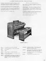
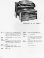


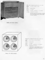
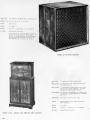

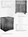


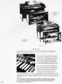


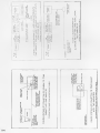
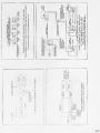


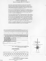
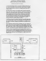

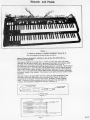

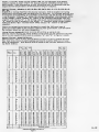
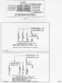


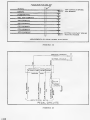
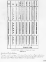


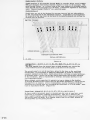


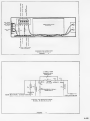
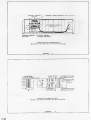


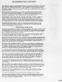
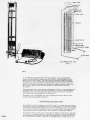
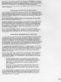
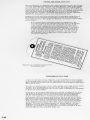
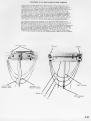

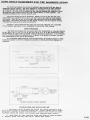
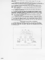
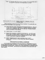
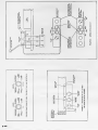


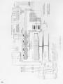
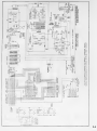
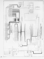
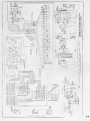

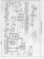
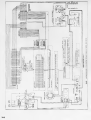
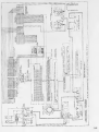

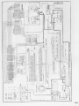

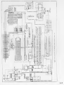


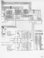


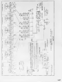
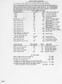

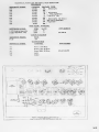

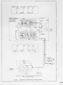

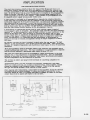

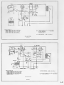


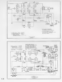
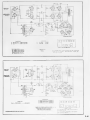

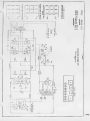

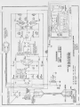

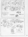
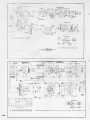

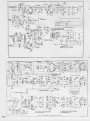
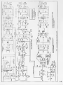


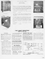
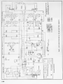
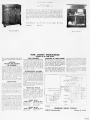
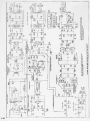


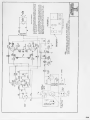
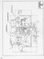

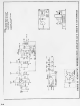
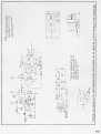


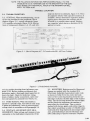
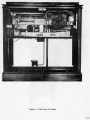


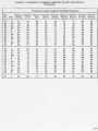
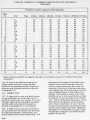
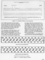

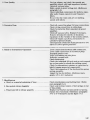


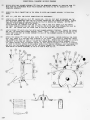


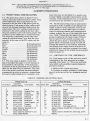
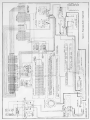
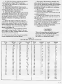
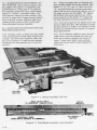


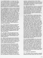
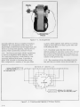

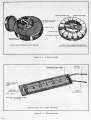
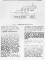
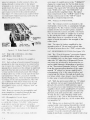

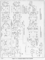


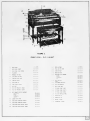


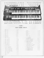
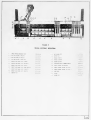
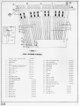

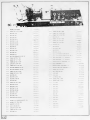

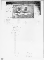

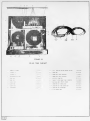


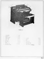
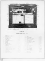
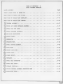
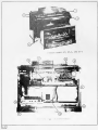
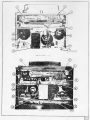


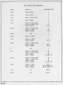

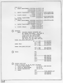
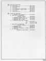


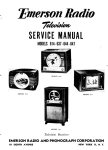


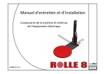

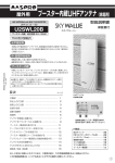
![Neuchâtel [pdf: 5Mo]](http://vs1.manualzilla.com/store/data/006470727_1-8320975ecafd3b079a4abdf032676ee2-150x150.png)