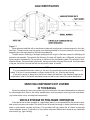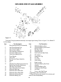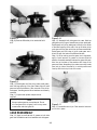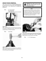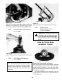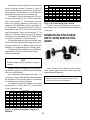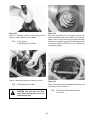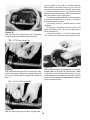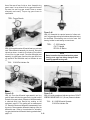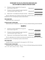
1
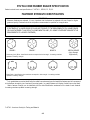
Spicer Single Speed Axle
®
Service Manual
Spicer® 70HD, 276, 80, 286
AXSM-0053
April 2001
INDEX
SECTION 1
GENERAL INFORMATION
PAGE
Important Safety Notice . . . . . . . . . . . . . . . . . . . . . . . . . . . . . . . . . . . . . . . . . . . . . . . . . . . . . 1-1
Safety Precautions . . . . . . . . . . . . . . . . . . . . . . . . . . . . . . . . . . . . . . . . . . . . . . . . . . . . . . . . 1-2
Axle Identification . . . . . . . . . . . . . . . . . . . . . . . . . . . . . . . . . . . . . . . . . . . . . . . . . . . . . . . . 1-3
Servicing Components Not Covered In This Manual . . . . . . . . . . . . . . . . . . . . . . . . . . . . . . . . . . 1-3
Vehicle Storage or Prolonged Inoperation . . . . . . . . . . . . . . . . . . . . . . . . . . . . . . . . . . . . . . . . 1-3
Exploded View of Axle Assembly . . . . . . . . . . . . . . . . . . . . . . . . . . . . . . . . . . . . . . . . . . . . . . . 1-4
Parts Description . . . . . . . . . . . . . . . . . . . . . . . . . . . . . . . . . . . . . . . . . . . . . . . . . . . . . . . . . 1-4
SECTION 2
SERVICE TOOLS
Procurement . . . . . . . . . . . . . . . . . . . . . . . . . . . . . . . . . . . . . . . . . . . . . . . . . . . . . . . . . . . 2-1
Service Tool Part Numbers and Description . . . . . . . . . . . . . . . . . . . . . . . . . . . . . . . . . . . . . . . 2-1
SECTION 3
CARRIER SECTION - SERVICE PROCEDURES
Disassembly . . . . . . . . . . . . . . . . . . . . . . . . . . . . . . . . . . . . . . . . . . . . . . . . . . . . . . . . . . . . 3-1
Ring Gear Removal . . . . . . . . . . . . . . . . . . . . . . . . . . . . . . . . . . . . . . . . . . . . . . . . . . . . . . . . 3-2
Servicing Standard Differential Case Assembly . . . . . . . . . . . . . . . . . . . . . . . . . . . . . . . . . . . . . 3-2
Case Disassembly . . . . . . . . . . . . . . . . . . . . . . . . . . . . . . . . . . . . . . . . . . . . . . . . . . . . . . 3-2
Case Reassembly . . . . . . . . . . . . . . . . . . . . . . . . . . . . . . . . . . . . . . . . . . . . . . . . . . . . . . 3-3
Drive Pinion Removal . . . . . . . . . . . . . . . . . . . . . . . . . . . . . . . . . . . . . . . . . . . . . . . . . . . . . . 3-4
Ring Gear & Pinion Gear Assembly (Theory) . . . . . . . . . . . . . . . . . . . . . . . . . . . . . . . . . . . . . . . 3-5
Establishing Pinion Gear Depth Using Service Tool Gages . . . . . . . . . . . . . . . . . . . . . . . . . . . . . 3-6
Assembly of Differential . . . . . . . . . . . . . . . . . . . . . . . . . . . . . . . . . . . . . . . . . . . . . . . . . . . . 3-1
Worksheet for Calculating Ring Gear Backlash & Differential
Bearing Preload Shims . . . . . . . . . . . . . . . . . . . . . . . . . . . . . . . . . . . . . . . . . . . . . . . . . . 3-13
Applying RTV Silicone Gasket Sealer to Cover Plate . . . . . . . . . . . . . . . . . . . . . . . . . . . . . . . . 3-15
SECTION 4
SPECIFICATIONS
Differential Lubrication . . . . . . . . . . . . . . . . . . . . . . . . . . . . . . . . . . . . . . . . . . . . . . . . . . . . . 4-l
Axle Lubricant Change Schedule . . . . . . . . . . . . . . . . . . . . . . . . . . . . . . . . . . . . . . . . . . . . . . . 4-1
i
Wheel Bearing Lubrication . . . . . . . . . . . . . . . . . . . . . . . . . . . . . . . . . . . . . . . . . . . . . . . . . . . 4-1
Submersion or Deep Water Fording . . . . . . . . . . . . . . . . . . . . . . . . . . . . . . . . . . . . . . . . . . . . . 4-1
RTV Silicone Rubber Sealer Specification . . . . . . . . . . . . . . . . . . . . . . . . . . . . . . . . . . . . . . . . 4-2
Fastener Strength Identification . . . . . . . . . . . . . . . . . . . . . . . . . . . . . . . . . . . . . . . . . . . . . . . 4-2
Wrench Tightening Torque Specifications . . . . . . . . . . . . . . . . . . . . . . . . . . . . . . . . . . . . . . . . . 4-3
Pinion Bearing and Differential Bearing Preload Specification . . . . . . . . . . . . . . . . . . . . . . . . . . 4-3
Backlash Specification-Drive Gear to Drive Pinion . . . . . . . . . . . . . . . . . . . . . . . . . . . . . . . . . . . 4-3
Drive Pinion Gear Depth Specification . . . . . . . . . . . . . . . . . . . . . . . . . . . . . . . . . . . . . . . . . . . 4-3
Wheel Bearing Specification . . . . . . . . . . . . . . . . . . . . . . . . . . . . . . . . . . . . . . . . . . . . . . . . . 4-3
ii
SECTION 1
GENERAL INFORMATION
IMPORTANT SAFETY NOTICE
Should an axle assembly require component parts replacement, it is recommended that “Original Equipment” replacement parts be used. They may be obtained through your local service dealer or other original
equipment manufacturer parts supplier. CAUTION: THE USE OF NON-ORIGINAL EQUIPMENT REPLACEMENT
PARTS IS NOT RECOMMENDED AS THEIR USE MAY CAUSE UNIT FAILURE AND/ OR AFFECT VEHICLE SAFETY.
Proper service and repair is important to the safe, reliable operation of all motor vehicles or driving axles
whether they be front or rear. The service procedures recommended and described in this service manual are
effective methods for performing service operations. Some of these service operations require the use of tools
specially designed for the purpose. The special tool should be used when and as recommended.
CAUTION: EXTREME CARE SHOULD BE EXERCISED WHEN WORKING ON COMPO- NENTS UTILIZING
SNAP RINGS OR SPRING LOADED RETENTION DEVICES. FOR PERSONAL SAFETY, IT IS RECOMMENDED
THAT INDUSTRIAL STRENGTH SAFETY GOGGLES OR GLASSES BE WORN WHENEVER REPAIR WORK IS
BEING DONE ON ANY VEHICLE OR VEHICLE COMPONENTS.
It is impossible to know, evaluate and advise the service trade of all conceivable ways in which service
might be done or of the possible hazardous consequences of each way.
Accordingly, anyone who uses a service procedure or tool which is not recommended must first satisfy
himself thoroughly that neither his safety or vehicle safety will be jeopardized by the service methods he
selects.
WARNING
Some vehicle manufacturers may require the assembly of brake components on Dana axles that utilize
materials containing asbestos fibers.
BREATHING ASBESTOS DUST MAY BE HAZARDOUS TO YOUR HEALTH AND MAY CAUSE SERIOUS
RESPIRATORY OR OTHER BODILY HARM.
Follow O.S.H.A. standards for proper protective devices to be used when working with asbestos materials.
SILICONE RUBBER SEALANT (RTV) AND LUBRICATING GREASE AND OILS
Silicone rubber sealant is used as a gasket material on Dana axles, as well as various lubricants for
lubricating purposes. Before using any of these materials, one should become familiar with and follow all
safety precautions as recommended by the product manufacturer/supplier. All personnel involved with these
materials should follow good industrial hygiene practices (e.g. before eating, hands and face should be
thoroughly washed. Eating, drinking and smoking should be prohibited in areas where there is potential for
significant exposure to these materials).
When discarding any of the materials, observe all local, state, and federal laws and regulations for proper
disposal procedures.
1-1
Safety Precautions
This symbol warns of possible personal injury.
A serious or fatal injury can
occur . . .
• if you lack proper training
• if you fail to follow proper
procedures
• if you do not use proper
tools and safety equipment
• if you assemble components
improperly
• if you use incompatible
components
• if you use worn-out or
damaged components
• if you use components
in a non-approved
application
SAFETY GLASSES SHOULD BE WORN AT ALL
TIMES WHEN WORKING ON VEHICLES OR
VEHICLE COMPONENTS.
1-2
AXLE IDENTIFICATION
Figure 1-1
Spicer axles are identified with a manufacturing date and complete part numbers stamped on the righthand tube. The part number may also appear on a metal tag attached to the cover plate by the cover screws,
depending upon the requirements of the vehicle manufacturer.
The part number, consisting of six digits reading from left to right, is the basic number for identifying the
particular axle assembly. The seventh digit following the dash will identify ratio, differential, and end yoke
options used in the assembly. The next group of numbers is the manufacturing date of the axle and is interpreted as follows. The first number is the month, the second number is the day of the month, the third number
is the year, the fourth is the line that built the axle, and the letter is the shift.
NOTE
It is recommended that when referring to the axle, the complete part number and build date be obtained. To do this, it may be necessary to wipe or scrape off dirt, etc., from the axle housing.
If the axle is unique on design such that the unit cannot be identified in the standard manner as described above, refer to the vehicle manufacturer’s service and/or parts manual for proper identification.
SERVICING COMPONENTS NOT COVERED
IN THIS MANUAL
Service procedures for some components may not be covered in this manual because they are unique to
the vehicle application. Refer to the vehicle manufacturer’s service manual for servicing those components.
(e.g. brakes, hubs, rotors, and wheel end components).
VEHICLE STORAGE OR PROLONGED INOPERATION
If the vehicle has not been operated on a regular daily basis, it is recommended that the vehicle be operated at least once every two weeks. The vehicle should be moved far enough to cause the drivetrain components to make several complete revolutions. This procedure will help assure that all internal components
receive adequate amount of lubrication to help reduce component deterioration caused by an undesirable
environment (e.g. high humidity).
1-3
EXPLODED VIEW OF AXLE ASSEMBLY
Figure 1-2
The model 80 single-speed axle assembly is an integral-type housing. Shown in figure 1-2 is a Model 80
full-float design.
Item
1
2
3
4
5
6
7
8
9
10
11
12
13
14
15
16
17
18
19
20
Part Description
Ring Gear and Drive Pinion Assembly
Inner Pinion Bearing Cone
Inner Pinion Bearing Cup
Pinion Position Shims
Pinion Bearing Preload Shims
Outer Pinion Bearing Cup
Outer Pinion Bearing Cone
Thrust Washer
Pinion Seal
End Yoke and Flinger Assembly
Washer
Nut
Shipping Plug (Shipping purposes only
Removed by vehicle manufacturer)
Side Gear Thrust Washer
Pinion Mate Gear Thrust Washer
Differential Side Gear
Differential Pinion Mate Gear
Differential Pinion Mate Shaft
Differential Outboard Spacer
Differential Bearing Cup
Item
21
22
Part Description
Differential Bearing Cone
Differential Bearing Preload and
Backlash Shims
23
Ring Gear Screw
24
Differential Case
25
Roll Pin (Pinion Mate Shaft)
26
RTV Sealant
*27
Identification Tag
28
Pill Plug
29
Cover Plate
30
Cover Screw
31
Brake Line Clip
32
Differential Bearing Cap Screw
33
Housing
**34
Differential Bearing Cap
35
Gasket-Axle Shaft Flange
36
Axle Shaft
37
Screw - Axle Shaft Flange
*Specified by vehicle manufacturer.
**Differential bearing caps are part of the housing and
cannot be serviced separately.
1-4
SECTION 2
SERVICE TOOLS
PROCUREMENT
Throughout the manual reference is made to certain tool numbers whenever special tools are required.
These tool numbers
are numbers of Miller Special Tools, 326 15 Park Lane. Garden City, MI 48135. They are used herein for
customer convenience only. Dana makes no warranty or representation to these tools.
Miller Tool Number
DD-914-8
DD-914-99
DD-914-95
D-115
C-4308
C-4204
D-4308
D-389
DD-914-42
DD-914-42
C-3339
W-129-B
6776
DD-914-7
C-4171
C-1490
D-159
6775
D-191
DD-914
DD-914-P
D115-2, 6739
8152
D-131
6719
Description
2 Jaw Puller
Adapter Ring
Adapters
Adapters
Arbor*
Bearing Cup Installer
Bearing Cup Installer*
Bearing Cup Installer
Bearing Installer
Button
Button
Dial Indicator Set
Differential Spreader
Dummy Differential Bearing Set*
Extension
Handle
Installer
Long Handle break-over bar (wrench)
Pinion Bearing Cup Remover
Pinion Height Set*
Pinion Yoke Installer
Press
Press
Scooter Gage**
Slide Hammer
Torque Multiplier***
Torque Wrench
Yoke Holder
* Gage set for setting differential bearing preload , gear backlash, and pinion position.
** Consist of D-106-5 dial indicator and D-115-2 Scooter Block.
*** The Torque Multiplier increases torque (4 to 1) by means of gear ratio: 1/2" drive (female), 1/4" drive (male).
2-1
NOTES
SECTION 3
CARRIER SECTION
DISASSEMBLY
NOTE
The photos or pictures contained herein are
for illustrative and instructional purposes only. The
appearance of your axle assembly and/or
components may vary from that shown. However,
the service procedures described will apply.
If it becomes necessary to disassemble any
parts inside the carrier, it is suggested that the entire
axle be removed from the vehicle and held tight in
a stand or rack.
All dimensions are in inches unless otherwise
stated. Dimensions in parentheses followed by mm
are in millimeters.
Figure 3-2
Step (3) Mount spreader to housing. DO NOT SPREAD
CARRIER OVER ,015 (.38 mm). Use dial indicator as
shown.
WARNING: When removing axle assembly,
make sure vehicle is properly supported.
Improperly supported vehicle can cause
serious injury or death. Follow vehicle
manufacturers recommendations for
proper axle assembly removal
procedures.
TOOL: W- 129-B Differential Spreader
C-3339 Dial Indicator Set
Step (1) Remove cover plate from housing and drain
lubricant.
NOTE
Before removing differential case assembly, make
sure the axle shafts are pulled out far enough for
clearance to allow removal.
Figure 3-3
Step (4) Pry differential case from carrier with two pry
bars. After differential case has been removed, remove
spreader. Use caution to avoid damage to components.
Tag bearing cups indicating from which side they were
removed from. See note below regarding the use of
bearings.
Figure 3-1
Step (2) Remove bearing caps. Note mating letters stamped
on caps and carrier. This is important at time of assembly
as they are to be assembled exactly as removed. Letters or
numbers are in vertical and horizontal position.
NOTE
It is recommended that whenever bearings are
removed, they are to be replaced with new ones,
regardless of mileage.
3-1
RING GEAR REMOVAL
Figure 3-4
Step (5) Note the differential bearing outboard spacers
located on each side of the differential bearing bore.
Remove and tag which side they were removed from. Ring
gear side or opposite side. They will be reused during
assembly, unless damaged or worn.
Figure 3-6
Step (7) Place differential case in vise or suitable holding
fixture. Remove ring gear screws. Leave 4 screws loosely
assembled 90 degrees apart. Place assembly on a solid
bench. Tap screws alternately and evenly to free ring gear
from differential case. Remove screws and ring gear.
Discard ring gear screws. Ring gear screws are to be
replaced with new ones at time of reassembly.
NOTE
Check outboard spacers for damage. (e.g. caused
by worn bearings). If damaged, they should be
replaced with new ones at time of reassembly.
SERVICING STANDARD
DIFFERENTIAL CASE ASSEMBLY
The differential assembly may be serviced at this time, if
required. If differential case, side gears and pinion mate
gears are useable and do not require servicing, proceed to
DRIVE PINION REMOVAL.
CASE DISASSEMBLY
Figure 3-5
Step (6) Remove differential bearing cones with a puller
as shown. Tag cones indicating from which side they were
removed from.
TOOL:
DD-914 Press
DD-914-99 Adapters
DD-914-8 Adapter Ring
DD-914-7 Extension
DD-914-42 Button
WARNING: When pulling bearings, do
not allow differential assembly to fall. It
can strike legs or feet and may cause
serious injury.
Figure 3-7
Step (8) Remove roll pin with a small drift.
3-2
Figure 3-8
Figure 3-10
Step (9) Remove differential pinion mate shaft with
drift.
Step (13) Assemble both side gears into case. Hold top
side gear up with fingers. Assemble one pinion mate gear.
Rotate gears until pinion mate gear is directly in the center
of the small opening of the case. Line up the other pinion
mate gear with the gear which has just been assembled.
Rotate gears until the holes of pinion mate gears are in
direct line with the holes of the differential case.
Step (14) Aft er making sure the gears are in alignment,
apply a small amount of grease to the new spherical
washers. Assemble washers between the gears and case.
Also line up the holes of the washers with those of the
gears and case. Assemble pinion mate cross shaft, make
sure lock pin hole of the shaft is in verticle position and
lined up with the lock pin hole of the case.
Figure 3-9
Step (10) Rotate gears until the pinion mate (small gears)
enter the large opening of the case. Remove pinion mate
gears and spherical washers. After removal of the pinion
mate gears, the side gear and thrust washers can be easily
removed.
Step (11) Inspect and replace components as
required.
NOTE
Always replace gears as a complete set. Do not
mix new gears with old gears, as this may cause
uneven wear and short gear life.
Figure 3-11
Step (15) Assemble new roll pin. Peen metal of case over
pin to lock in place.
CASE REASSEMBLY
Step (12) Apply a small amount of grease on both side
gear hubs. Assemble new thrust washers onto side gears.
3-3
DRIVE PINION REMOVAL
WARNING: Gear teeth may have sharp
edges. When handling gears, use care to
avoid personal injury.
Step (16) Secure end yoke or flange with holding wrench,
and remove pinion nut and washer. NOTE: PINION NUT
HAS 500 LBS. FT. (677.9 Nom) MAX. OF TORQUE FOR
RETENTION.
TOOL:
NOTE
On the spline end of the pinion, there are bearing
preload shims. These shims may stick to the pinion
or bearing or even fall out. These shims are to be
collected and kept together since they will be used
later in assembly. Try not to mutilate shims. If’ shims
are mutilated, replace with new ones.
67 19 Yoke Holder
Torque Multiplier
Long Handle break-over bar (wrench)
Figure 3-12
Step (17) Remove end yoke or flange with tools as shown.
If end yoke or flange shows wear in the area of the seal
contact surface, it should be replaced.
TOOL:
2 Jaw Puller
Figure 3-14
Step (19) Pull out pinion seal with puller as shown. Discard
seal. REPLACE WITH NEW ONE AT TIME OF ASSEMBLY.
Remove bearing cone and outer thrust washer.
TOOL:
Figure 3-13
Step (18) Remove pinion by tapping with a rawhide or
plastic hammer. Catch the pinion with your hand to prevent
it from falling and being damaged.
3-4
D- 131 Slide Hammer
Figure 3-15
Figure 3-1 7
Step (20) Turn nose of carrier down. Remove outer pinion Step (22) Remove pinion bearing with tools as shown.
bearing cup. Locate driver on back edge of cup; drive cup
out of carrier. CAUTION: DO NOT NICK CARRIER BORE.
TOOL:
TOOL:
D-159 Pinion Bearing Cup Remover
C-4171 Handle
DD-914-P Press
DD-914-8 Adapter Ring
DD-914-95 Adapters
WARNING: Do not allow gear to fall. It can
strike legs or feet and may cause serious
injury. Gear teeth may have sharp edges.
When handling, use care to avoid cutting
hands.
RING & PINION GEAR
ASSEMBLY THEORY
Figure 3-16
Step (21) Remove the inner bearing cup with tools as shown.
TOOL:
C-4307 Bearing Cup Remover
C-4171 Handle
NOTE:
Shims are located between the bearing cup and
carrier bore and may also include an oil baffle,
depending upon the application. If shims and baffle
are bent or nicked, they should be replaced at time
of assembly.
Figure 3-18 (View of ring 81 pinion set)
Step (23) Ring gears and pinions are supplied in matched
sets only. Matching numbers on both the pinion and ring
gear are etched for verification. If a new gear set is being
used, verify the numbers of each pinion and ring gear before
proceeding with assembly.
The nominal distance from the centerline of the ring
gear to the button end of the pinion for the Model 80 axle
is 3.500 (88.9 mm).
3-5
On the button end of each pinion, there is etched
a plus (+) number, a minus (-) number, or a zero (0)
which indicates the best running position for each particular gear set. This dimension is controlled by the
shimming behind the inner pinion bearing cup.
For example: If a pinion is etched a plus +3 (m+8),
this pinion would require .003 (.08 mm) less shims
than a pinion etched “0”. This means by removing
shims, the mounting distance of the pinion is increased to 3.503 (88.98 mm), which is just what a +3
(m+8) indicates. Or if a pinion is etched -3 (m-8), we
would want to add .003" (.08 mm) more shims than
would be required if the pinion were etched “0”. By
adding .003 (08 mm) shims, the mounting distance
of the pinion was decreased to 3.497 inches (88.82
mm) which is just what a -3 (m-8) indicates.
If the old ring and pinion set is to be reused, measure the old shim pack and build a new shim pack to
this same dimension. If a baffle is used in the axle
assembly, it is considered as part of the shim pack.
To change the pinion adjustments, use different
combination of the pinion shims which come in
different thicknesses.
Old Pinion
Marking
-2
-1
0
+1
+2
+3
+4
+0.008
+0.007
+0.006
+0.005
+0.004
+0.003
+0.002
+0.001
0
+3
+0.007
+0.006
+0.005
+0.004
+0.003
+0.002
+0.001
0
-.0.001
+2
+0.006
+0.005
+0.004
+0.003
+0.002
+0.001
0
-.0.001
-0.002
+1
+0.005
+0.004
+0.003
+0.002
+0.001
0
-.0.001
-0.002
-0.003
0
+0.004
+0.003
+0.002
+0.001
0
-.0.001
-0.002
-0.003
-0.004
+0.003
+0.002
+0.001
0
-.0.001
-0.002
-0.003
-0.004
-0.005
-2
+0.002
+0.001
0
-.0.001
-0.002
-0.003
-0.004
-0.005
-0.006
-3
+0.001
0
-.0.001
-0.002
-0.003
-0.004
-0.005
-0.006
-0.007
-4
0
-.0.001
-0.002
-0.003
-0.004
-0.005
-0.006
-0.007
-0.008
0
+3
+5
+8
+10
+.20
+.18
+.15
+.13
+.10
+.08
+.05
+.03
+10
0
+8
+.18
+.15
+.13
+.10
+.08
+.05
+.03
0
-.03
+5
+.15
+.13
+.10
+.08
+.05
+.03
0
-.03
-.05
+3
+.13
+.10
+.08
+.05
+.03
0
-.03
-.05
-.08
0
+.10
+.08
+.05
+.03
0
-.03
-.05
-.08
-.10
-3
+.08
+.05
+.03
0
-.03
-.05
-.08
-.10
-.13
-5
+.05
+.03
0
-.03
-.05
-.08
-.10
-.13
-.15
-5
+.03
0
-.03
-.05
-.08
-.10
-.13
-.15
-.18
-10
0
-.03
-.05
-.08
-.10
-.13
-.15
-.18
-.20
View of master pinion bearing, pinion height
block, scooter gage, cross arbor, arbor discs and
master differential bearings.
NOTE
Make sure that all carrier bores are free from all
nicks, dirt or any other contamination.
+4
-1
-3
Figure 3-21
New Pinion Marking
-3
-5
ESTABLISHING PINION GEAR
DEPTH USING SERVICE TOOL
GAGES.
Measure each shim separately with a micrometer and add together to get total shim pack thickness
from the original build-up.
If a new gear set is being used, notice the (+) or
(-) etching on both the old and new pinion and adjust
the thickness of the new shim pack to compensate
for the differences of these two figures.
For example: If the old pinion reads +2 (m+5) and
the new pinion is -2 (m-5), add .004" (. 10 mm) shims
to the original shim pack.
-4
-8
Figure 3-20 (Pinion Setting Chart - Metric)
If metric, pinion will be etched (m+ some number). Example (m+5). Use these charts as a guideline
to set pinion.
NOTE
If baffle or slinger is bent or mutilated, it should be
replaced.
Old Pinion
Marking
New Pinion Marking
-10
Figure 3-19 (Pinion Setting Chart - English U.S.
Standard)
3-6
Figure 3-22
Step (24) Assemble the outer pinion bearing cup into
carrier as shown. Make sure cup is seated.
Figure 3-24
Step (26) Assemble pinion with master bearing into
housing. Assemble outer pinion bearing cone, end yoke,
washer, and nut. Torque nut until pinion gear and master
bearing is snug (seated) in housing. The pinion gear should
not have any end play. NOTE: Do not try to rotate pinion
using master bearing.
TOOL: C-4171 Handle
C-4308 Bearing Cup Installer
Figure 3-23
Step (25) Assemble master pinion bearing on pinion.
Figure 3-25
Step (27) Place arbor discs (large diameter) and arbor into
cross bores of carrier as shown.
TOOL: C-4204 Bearing Cup lnstaller
TOOL: 6776 Dummy Differential Bearing Set
D-115 Arbor
WARNING: Gear teeth may have sharp
edges. When handling gears, use care to
avoid personal injury.
3-7
over top of arbor, it will travel in a clockwise direction.
When indicator is on center of arbor (on top) it will stop
traveling in a clockwise direction. If indicator starts to travel
in a counter-clockwise direction, this means you have
passed the center (top) of the arbor. Record only the reading
when the indicator is at the highest point.
This reading indicates the amount of shims necessary
to obtain the shim pack plus (+) or minus (-) the etching
on the button end of the pinion.
If the etching is zero (0), the shim pack will remain
unchanged.
For example: If the pinion is etched +3 (m+8), this
pinion would require .003" (.08 mm) less shims than a
pinion etched zero (0).
If the pinion is etched -3 (m-8), this would require.
003" (.08 mm) more shims than a pinion etched zero (0).
Figure 3-26
Step (28) Place pinion height block on top of the button
end of the pinion gear and against arbor as shown.
TOOL: 6775 Pinion Height Set
Figure 3-29
Figure 3-27
Step (31) Measure each shim separately with a micrometer
and add together to get total shim pack thickness. If baffle
is required it is to be included in the shim pack. If slinger
is used between the inner bearing cone and thrust face of
pinion, the slinger is also to be measured and included as
part of the total shim pack.
Step (29) Place scooter gage on pinion height block. Apply
pressure with fingers, making sure the gage is flat on the
pinion block. While pressure is applied, set indicator at
zero “0”.
TOOL:
D115-2,6739 Scooter Gage
Figure 3-28
Step (30) Slide scooter gage over arbor. As gage slides
3-8
Figure 3-30
Figure 3-32
Step (32) Place the required amount of shims (and
baffle if used) in the inner bearing bore. Drive the
inner bearing cup into the carrier. Make sure cup is
seated.
Step (34) Assemble pinion into carrier. Assemble outer
pinion bearing cone, thrust washer, and end yoke onto
pinion spline.
NOTE
Do not assemble preload shims or pinion oil seal at
this time.
TOOL: C-4308 Bearing Cup Installer
C-4171 Handle
Use yoke installer as shown to assemble end
yoke onto spline of pinion.
TOOL: D- 191 Pinion Yoke Installer
6719 Yoke Holder
Figure 3-31
Step (33) Assemble inner bearing cone (and slinger if used)
on pinion. Drive bearing on shaft until it is
completely seated.
Figure 3-33
TOOL: D-389 Bearing Installer
Step (35) Assemble washer and pinion nut. Torque nut
until it requires 10 Lbs. in. 1.13 Nom of torque to rotate
the pinion. Rotate pinion several times before checking
pinion position. This is to seat the bearings and assure a
more accurate reading when checking the pinion depth
setting.
TOOL: Torque Wrench
3-9
Step (37) Apply a light coat of hypoid lubricant on the lip
of pinion seal and assemble into carrier.
TOOL:
8152 Seal Installer
C-4171 Handle
Figure 3-34
Step (36) Place arbor and discs (large diameter end) into
cross bore of carrier. Place pinion height block on button
end of pinion. Set dial indicator on height block (high step
of block). Set dial indicator at zero (0). Slide scooter gage
across or over arbor.
Indicator will read a plus (+) or minus (-) at its highest
point, depending on the etching of the pinion.
NOTE
Indicator reading within .002 (.05 mm) of etching is
considered acceptable. If pinion position is found to
be within specification, continue with build-up. If pinion
position is not within specification, change shim pack
thickness under inner bearing cup.
Figure 3-36
Step (38) Assemble pinion, end yoke, washer, and new
pinion nut. Torque nut to specification.
TOOL:
6719 Yoke Holder
Torque Wrench
NOTE: Torque wrench must be capable of 500 lbs. ft. (677.9
N•m) torque.
Remove pinion nut, washer, end yoke, and pinion.
Assemble preload shims onto pinion.
NOTE: If old shims are available, measure shim pack and
build up new shim pack using new shims of the same
thickness. If old shim pack is not available for reference,
build shim pack up to .060 (1.52 mm) thick. This will
provide a starting point and may require adjustment.
Figure 3-37
Step (39) Using an in. Lbs. torque wrench as shown, rotate
pinion. Torque to rotate pinion should be within
specification. To increase preload, remove shims, to
decrease preload add shims.
Figure 3-35
3-10
Figure 3-38
Figure 3-40
The illustration in figure 338 shows the arrow in the pinion
pointing in two directions. The direction pointing towards
the end yoke indicates that by removing pinion position
shims, the distance from the centerline of the axle to the
pinion button is increased giving a plus reading. The preload
shim pack does not effect the pinion depth setting. Arrows
on the ring gear illustrate the method to increase or
decrease backlash and differential bearing preload.
Step (41) Assemble the differential bearing outboard
spacers into the carrier housing, as removed in step 5,
figure 34.
Assemble differential case into carrier (less ring gear).
Mount dial indicator with a magnetic base as shown. Locate
tip of indicator on flat surface of case. Force differential
assembly as far as possible in the direction towards the
indicator. With force still applied, set indicator at zero (0).
TOOL: C-3339 Dial Indicator Set
ASSEMBLY OF DIFFERENTIAL
NOTE
Dial indicator should have a minimum travel capability
of .200 (5.08 mm).
Force the differential assembly as far as it will go in
the opposite direction. Repeat these steps until you have
obtained the same reading. Record the reading of the
indicator on the worksheet, page 313. This reading will be
measurement “A”. After making sure the readings are
correct, remove indicator and differential assembly from
housing. Remove master bearings from hubs and set aside.
Figure 3-39
Step (40) Assemble master differential bearings onto case.
Remove all nicks, burrs, dirt etc., from hubs to allow master
bearings to rotate freely.
TOOL: 6776 Dummy Differential Bearing Set
Figure 3-41
Step (42) Place case assembly in a vise. Be sure flange
3-11
face of the case is free of nicks or burrs. Assemble ring
gear to case. Line up holes of the ring gear with those of
the case. Use new ring gear screws. Draw up screws
alternately and evenly. Torque ring gear screws to
specification.
TOOL: Torque Wrench
Figure 3-44
Step (45) Assemble the required amount of shims onto
hub (ring gear side) and opposite side as determined using
the worksheet. Place bearing cone on hub of case. Use
bearing installer to seat bearing cone as shown.
TOOL:
Figure 3-42
Step (43) Assemble master differential bearings onto case
hubs. Place differential assembly into housing. Set up dial
indicator as shown. Locate tip of indicator on flat surface
of one of the ring gear screws. Force the differential case
assembly (ring gear) away from the pinion gear. With force
still applied to the differential case, set indicator at zero
“0”.
TOOL: C-3339 Dial Indicator Set
Figure 3-43
C- 1490 Installer
C-4171 Handle
DD-914-42 Button
NOTE
Button is used to raise case from bench to protect
bearing cone cage from being damaged when
installing opposite bearing cone.
Figure 3-45
Step (44) Force the differential case assembly and ring
Step (46) Install spreader and indicator as shown. DO NOT
gear into mesh with the pinion gear. Rock ring gear to allow
SPREAD CARRIER OVER .015 (.38 mm). Remove indicator.
the teeth of the gear to mesh. Repeat until the same reading
is obtained each time. Record this reading on the
TOOL: W- 129 B Differential Spreader
worksheet, page 313. This reading will be measurement
C-3339 Dial Indicator Set
“B”. Remove indicator and differential case assembly from
the carrier. Remove master differential bearings from the
differential case. Refer to the worksheet for calculating
ring gear backlash and differential bearing preload shims,
page 3-13.
3-12
WORKSHEET FOR CALCULATING RING GEAR BACKLASH
AND DIFFERENTIAL BEARING PRELOAD SHIMS
(1)
(2)
(3)
Total amount of space measured without ring gear as
shown in step 41, figure 3-40
Measurement A
Total amount of space measured with gear set assembled
in carrier as shown in step 44, figure 3-43
Measurement B
Measurement A minus Measurement B equals calculated
Measurement C
After the measurements and calculations have been made, assemble the shim packs using the figures
determined in A, B, & C, and adjusting the pack as described below.
RING GEAR SIDE:
Assemble shim pack to measurement B.
OPPOSITE SIDE OF RING GEAR:
Assemble shim pack to measurement C. Add .010 (.25 mm) for differential bearing preload and backlash.
EXAMPLE
(1)
(2)
(3)
Total amount of space measured without ring gear as
shown in step 41, figure 3-40
Measurement A .105" (2-67 mm)
Total amount of space measured with gear set assembled
in carrier as shown in step 44, figure 3-43
Measurement B .065" (1.65 mm)
Measurement A minus Measurement B equals calculated
Measurement C .040" (1.02 mm)
After the measurements and calculations have been made, assemble the shim packs using the figures
determined in A, B, & C, and adjusting the pack as described below.
RING GEAR SIDE:
Assemble shim pack to measurement B, In this example it is .065" (1.65 mm).
OPPOSITE SIDE OF RING GEAR
Assemble shim pack to measurement C. Add .010 (.25 mm) for differential bearing preload and backlash.
.040" + .010" = .050", (1.02 mm + 25 mm = 1.27mm).
3-13
Figure 3-46
Figure 3-48
Step (47) Assemble differential bearing cups to differential
bearing cones. Install differential assembly into carrier. Use
a rawhide or plastic hammer to seat differential assembly
into cross bores of carrier. Care should be taken to avoid
nicking the teeth of the ring gear and pinion during
assembly. Remove spreader.
Step (49) Check ring gear and pinion backlash in three
equally spaced points with dial indicator as shown.
Backlash should be within specification and cannot vary
more than .002 (-05 mm) between points checked.
TOOL: C-3339 Dial Indicator Set
WARNING: When differential assembly is
installed into carrier, use care to avoid
pinching hand or fingers between
differential bearing cup and carrier
housing.
Gear teeth may have sharp edges. When
handling gear, use care to avoid cutting
hands.
High backlash is corrected by moving the ring
gear closer to the pinion.
Low backlash is corrected by moving the ring gear
away from the pinion.
These corrections are made by switching shims
from one side of the differential case to the other.
Figure 3-49
Figure 3-47
Step (48) Install bearing caps. Make sure the letters
stamped on the caps correspond with those on the carrier.
Torque bearing cap screws to specification.
Step (50) Using an in. lb. torque e wrench as shown, rotate
pinion and differential assembly, Torque reading should
be within specifi ication. If preload is to high, remove an
equal amount of shims from both sides of the differential
case hubs. If preload is to low, add an equal amount of
shims to both sides of differential case hubs.
NOTE
If shims are added to one side only, it will affect
backlash reading.
TOOL: Torque Wrench
3-14
APPLYING RTV SILICONE
GASKET SEALER TO COVER PLATE
Figure 3-50
Step (51) Apply gasket sealer to cover plate and assemble
to carrier. Torque screws to specification.
TOOL:
Torque Wrench
NOTE
The cover face of the carrier and the flat surface of
the cover plate must be free of any oil film or foreign
material. Sealant material must meet specifications
as described in the specification section of this
manual.
Apply sealer to cover plate surface. Ensure that
the sealer bead is laid on the inside of the cover
screw holes. The bead is not to pass through the
holes or outside of the holes.
The bead is to be 1/8" to 1/4" (3.18 - 6.35 mm) high
and 1/8" to 1/4" (3.18 - 6.35 mm) wide.
Allow one hour cure time before filling carrier with
the proper amount of specified lubricant and vehicle
operation.
Assemble axle shafts and wheel end components.
Refer to your vehicle service manual for proper
wheel bearing setting specification.
3-15
NOTES
SECTION 4
SPECIFICATIONS
DIFFERENTIAL LUBRICATION
It is not our intent to recommend any particular brand or make of lubricant for the Spicer hypoid axle. However, an S.A.E.
8OW-90 multi-purpose gear lubricant meeting Mil. Spec. L-2105C, and suitable for 1 A.P.I. Service Classification GL5, is
suggested as a minimum requirement.
IMPORTANT
Motor vehicles are operated under various requirements, conditions, and environments. This manual specifies
the minimum requirements that the lubricants should meet. However, it is recommended that the lubricants
specified by the vehicle manufacturer be used. They may provide additional lubricating characteristics which may
be required for your vehicle’s operation. Contact your local service dealer or refer to your owner’s manual for
obtaining the proper lubricant specification.
AXLE LUBRICANT CHANGE SCHEDULE
The following schedule is a suggested lubricant change schedule. Lubricant in your vehicle may require more frequent
changes depending upon the environment in which it is operated in. Contact your local service dealer or refer to your
owner’s manual for obtaining the proper lubricant change schedule for your vehicle.
Drain lubricant at first oil change and refill with specified lubricant. FOR NORMAL ON HIGHWAY USE, change
lubricant every 100,000 miles or 24 months, whichever comes first. FOR OFF HIGHWAY, SANDY, DUSTY, OR WET
CONDITIONS, change lubricant every 25,000 miles or 6 months, whichever comes first.
Lubricant may be drained by removing the carrier cover plate. This also allows for visual inspection of the internal
components. Follow the service procedure in the manual for reassembly of the cover plate.
WHEEL BEARING LUBRICATION
Wheel bearings are lubricated by packing with grease. For grease packing it is recommended that a 2N.L.G.I. No. 2
lithium EP grease suitable for automotive wheel bearings be used. Contact your local vehicle service dealer or refer to
your owner’s manual for obtaining the proper lubricant specification, and maintenance schedule.
SUBMERSION OR DEEP WATER FORDING
If the vehicle is exposed to water deep enough to cover the hubs, it is recommended that the wheel ends be diassembled
and inspected for water damage and/or contamination.
In the event the carrier housing should become submerged in water, particularly if over the breather, it is recommended
that the hypoid gear lubricant be drained and internal parts be inspected for water damage and/or contamination.
Clean, examine, and replace damaged parts if necessary, prior to assembling the housing cover and refilling with the
specified hypoid lubricant.
NOTE
If the hubs are exposed to deep water, it is possible that the water could enter the carrier at the point the axle
shaft enters the tube in the wheel end. This could also necessitate the draining of the hypoid lubricant as described
above.
It is recommended that whenever bearings are removed, they be replaced with new ones, regardless of
mileage.
1
2
A.P.I. - American Petroleum Institute
N.L.G.I. - National Lubricating Grease Institute
4-1
RTV SILICONE RUBBER SEALER SPECIFICATION
Sealant material must meet specification of 1A.S.T.M. 1, GE 503, Z1, Z2, 23.
FASTENER STRENGTH IDENTIFICATION
IMPORTANT
Whenever fasteners are replaced, it is very important that the fastener be replaced with one of equal or higher
grade and quality. Fasteners should be torqued as recommended or specified for the application.
WARNING
IF FASTENERS OF A LOWER GRADE OR CLASS ARE TORQUED TO THE REQUIREMENTS OF A HIGHER GRADE
OR CLASS FASTENER, IT MAY RESULT IN COMPONENT FAILURE. (E.G. GRADE 5 FASTENER TORQUED TO THE
REQUIREMENTS OF A GRADE 8 FASTENER.)
GRADE 5
GRADE 7
GRADE 8
Customary (Inch) Bolts - Identification marks correspond to bolt strength - Increasing numbers
represent increasing strength.
SPECIAL GRADE
(High Strength
Applications)
Metric Bolts - Identification class numbers correspond to bolt strength - increasing numbers
represent increasing strength.
Figure 4-l
Inch grade fasteners can be identified by the radial lines embossed upon the head of the fastener and will correspond
to the fastener strength by two-lines less than actual grade (i.e. grade 8 fastener will display 6 radial lines on the head).
Metric fastener strength can be identified with the class identification embossed on the head of each fastener.
Increasing numbers represent increasing strength.
1
A.S.T.M. - American Society for Testing and Material
4-2
WRE
ENCH TIG
GHTENIN
NG TORQ
QUE SPE
ECIFICAT
TIONS
ws . . . . . . . . . . . . . . . . . . . . . . . . . . . . . . . . . . . . . . . . . . . . . . . . . . . . .
Cover Screw
Differential Bearing
B
Cap Screws
S
........................................
Drive Pinion
n Nut . . . . . . . . . . . . . . . . . . . . . . . . . . . . . . . . . . . . . . . . . . . . . . . . . . .
Fill Plug . . . . . . . . . . . . . . . . . . . . . . . . . . . . . . . . . . . . . . . . . . . . . . . . . . . . . . . . . .
Ring Gear Screws . . . . . . . . . . . . . . . . . . . . . . . . . . . . . . . . . . . . . . . . . . . . . . . . . .
LBS. FT. 1
35
5
80
0
470
0
25
5
220
0
N
N•m
47.5
1
108.5
6
637.2
3
33.9
2
298.3
PIN
NION BEA
ARINGAN
ANDDIFF
FERENTIA
AL BEAR
RING
PRELO
OAD SPEC
CIFICATIION
otate Drive Pin
nion Only (New
w bearings on
nly) . . . . . . . . . . . . . . . . . . . . .
Torque to Ro
Torque to Ro
otate Drive Pin
nion and Diffe
erential Case
Assembly (L
Less Axle Shaffts) (New bearrings only)
LB
BS. IN.
20
0-40
N•m
2.26 - 4.52
E1
SEE NOTE
BACK
B
LAS
SHSPEC
CIFICATIO
ON
Drive Gear to
o Drive Pinion
n ............................................
.005 - .008 (.13 --20 mm)
DR
RIVE PIN
NION GE
EAR DEPT
THSPEC
CIFICATIO
ON
Figure 4-2
The pinion setting
s
dimens
sion is measu
ured from the centerline of differential ca
arrier (center lline of ring ge
ear) to face off
pinion (butto
on), plus or minus
m
the etch
h on the butto
on of the pinio
on. This dimen
nsion must be
e held within ± .002 in (.05
mm). For ex
xample: The model
m
80 pinion
n setting dime
ension is 3.50
00 (88.9 mm). If the pinion e
etch is a +2, th
his dimension
becomes 3.5
502 (88.95 mm
m).
WHE
EEL BEA
ARING
R
SP
PECIFICA
ATION
SPECIFIEDB
BYVEHICLEM
MANUFACTUR
RER.CONTACT
TYOURLOCA
AL VEHICLESE
ERVICEDEALE
ERORREFER
RTOYOUR
VEHICLE SE
ERVICEMANU
UAL FOR OBTAINING
A
THE PROPER
P
WHE
EEL BEARING S
SPECIFICATIO
ON.
Notes:
(1) Torque
e to rotate drive pinion on
nly plus 6-8 lb
bs. in. (.68 - .90 N •m) fo
or ratios 4.63
3 to 5.13.
4-3
4
NOTES
Aftermarket
Group
ForDana
spec‘ing
or service assistance,
call 1.800.621.8084 or visit our website at www.spicerparts.com
PO Box 321
Toledo, Ohio 43697-0321
Warehouse
Distributor:
Dana
Commercial
Vehicle1.800.621.8084
Products Group
OE Technology
Dealers: 1.877.777.5360
3939
Drive
Maumee, Ohio, USA 43537
www.spicerparts.com
www.dana.com
AXSM-0053 Printed in U.S.A.
Copyright Dana Limited, 2012.
All rights reserved. Dana Limited.