1
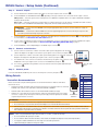
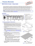
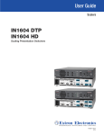
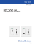
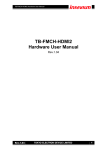
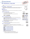
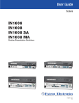
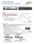
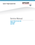
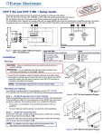
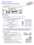
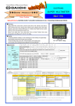
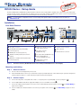
NTth: e complented
RTA
r
,a
om fo ctions e
IMPxO
tron.c instru
ng th
ww.e tallation onnecti e.
s
r to w
rc
ec
Refe guide, in ns befor wer sou
o
user cificatio
the p
spe roduct to
p
IN1604 Series • Setup Guide
The Extron IN1604 DTP and IN1604 HD Scaling Presentation Switchers are four input, HDCP-compliant video scalers that accept a wide variety
of audio and video formats. This guide allows an experienced user to set up and configure an IN1604 Series scaler. It covers how to perform basic
operations using the front panel controls and selected Simple Instruction Set (SIS™) commands.
NOTE:
For full installation, configuration, menus, connector wiring, and operation details, see the IN1604 Series User Guide, at
www.extron.com.
IMPORTANT:
Refer to www.extron.com for the complete
user guide, installation instructions, and
specifications before connecting the
product to the power source.
Installation
Rear Panel Features
100-240V ~ 0.5 A MAX
100-240V ~ 0.5 A MAX
OUTPUT
OUT
1 CONFIGURABLE
2
HDMI
3
4
B
1
HDMI
HDMI
INPUT
50-60 Hz
A
K
F
IN1604 DTP
1
IN
50-60 Hz
C
D
2
CONFIGURABLE
L
R
L
R
SIG
E
2
3
4 G
HDMI
3
CONTACT IN
LINK
OVER TP
HDBT RS-232 IR4
OUT
AUDIO
1
2
DTP
Tx Rx G Tx Rx
INPUT
L
1
2
3
OUT
4 +V
1
HDMI
TALLY OUT
RS-232
IN
HDMITx Rx G 1
2
REMOTE
G H I
L
R
L
R
AUDIO
M
HDMI
J
A
B
AC power connector
F
Configurable analog 15-pin HD (VGA)
connector (input 1)
Balanced or unbalanced analog
audio output connector
G
TP output connector
(IN1604 DTP only)
K
L
M
Unbalanced analog audio input connector
(input 1)
H
I
TP output switch (IN1604 DTP only)
Balanced or unbalanced analog audio input
connector (input 2)
J
Figure 1.
2
OUTPUT
Control Connections
E
3
4 +V
TALLY OUT
1
Output Connections
HDMI input connectors (inputs 2-4)
2
CONTACT IN
Power and Input Connections
C
D
L
IN1604 HD
3
4 G
RS-232
Tx Rx G
REMOTE
K
M
Contact closure connector
Tally connector
Remote RS-232 connector
RS-232 and IR Over TP
connector (IN1604 DTP only)
HDMI output connector
(IN1604 HD only)
Rear Panel Features (IN1604 DTP Shown Left and Unique IN1604 HD Features Shown Right)
Mounting and Cabling
Step 1 — Mount the device.
a.
Turn off or disconnect all equipment power sources.
b. Mount the IN1604 Series scaler on top of a flat surface using the provided rubber feet, under a table using an optional mounting kit for
under-the-desk mounting, or to a rack shelf using an optional rack shelf-mounting kit.
Step 2 — Connect inputs.
a.
Connect an analog video source (RGB, YUV, S-video, or composite) to the 15-pin HD (VGA) connector (see figure 1,
B)
C).
b. Connect digital HDMI or DVI (with an appropriate adapter) sources to the HDMI connectors (
c.
D). See Audio Wiring on
Connect an unbalanced analog audio source to the 3.5 mm, female TRS (tip-ring-sleeve) audio connector (
page 3 for more details.
E). See Audio Wiring on page 3 for more
d. Connect a balanced or unbalanced audio source to the 5-pole captive screw connector (
details.
1
IN1604 Series • Setup Guide (Continued)
Step 3 — Connect outputs.
a.
F).
Connect a balanced or unbalanced audio output device to the 5-pole captive screw connector (
H) depending on the type of device to be connected to the TP output connector.
b. For the IN1604 DTP, set the HDBT/DTP switch (
HDBT position — Select this position if the receiving device is an HDBaseT-compatible device. The output is HDMI with embedded
audio plus RS-232 and IR.
DTP position — Select this position if the receiving device is an Extron DTP device. The TP output is compatible with a DTP receiving
device and consists of HDMI with embedded audio, analog audio, RS-232 and IR, and remote power.
ATTENTION:
Position this switch BEFORE connecting the appropriate device to the TP connector. Failure to comply can
damage the endpoint.
ATTENTION :
Positionnez le sélecteur AVANT de connecter l’appareil approprié au connecteur TP. Ne pas respecter cette
procédure pourrait endommager le point de connexion.
c.
G). For cable wiring and
For the IN1604 DTP, connect a DTP receiver or HDBaseT-compatible device to the female RJ-45 connector (
recommendations, see Twisted Pair Recommendations below.
d. To pass serial or infrared data to a DTP receiver from an IN1604 DTP, connect a control device to the RS-232 and IR Over TP captive
screw connector (
). For wiring details, see RS-232 and IR Over DTP Wiring (IN1604 DTP Only) on page 3.
I
e.
J).
For the IN1604 HD, connect a digital display to the HDMI output connector (
Step 4 — Connect control devices.
a.
Connect contact closure devices or Extron “Show Me” cables (see the red pigtail on the “Show Me”
cable in the diagram to the right) to the Contact In 5-pole captive screw connector (see figure 1,
).
1
K
M
d. For control or configuration through USB, connect a host device to the front panel USB mini-B port
(see figure 2,
).
4 +V
CONTACT IN
1
L
For serial RS-232 control, connect a host device to the RS-232 5-pole captive screw connector on the
IN1604 DTP or the 3-pole captive screw connector on the IN1604 HD (see figure 1,
).
3
TALLY OUT
b. Connect tally devices or Extron “Show Me” cables (see the black pigtail on the “Show Me” cable in the
diagram to the right) to the Tally Out 5-pole captive screw connector (see figure 1,
).
c.
2
2
3
RS-232
4 G
Tx Rx G
REMOTE
Red
Black
“Show Me” Cable
Pigtail
B
Step 5 — Connect power.
Connect a 100-230 VAC, 50/60 Hz power source to the AC power connector (see figure 1,
A).
Pins:
12345678
Wiring Details
TIA/EIA-T568B
Pin
Twisted Pair Recommendations
Extron recommends using the following practices to achieve full transmission distances and reduce
transmission errors:
•
Use Extron XTP DTP 24 SF/UTP cable for the best performance. At a minimum, Extron recommends
24 AWG, solid conductor, STP cable with a minimum bandwidth of 400 MHz.
•
Terminate cables with shielded connectors to the TIA/EIA-T568B standard (see right).
•
Limit the use of more than two pass-through points, which may include patch points, punch down
connectors, couplers, and power injectors. If these pass-through points are required, use shielded
couplers and punch down connectors.
ATTENTION:
T568A
Wire Color
Pin
Orange
3 3 White-green
White-orange
4 4 Blue
Blue
Blue
White-b
Green
8
White-brown
8 Brown
Brown
• DTP remote power is intended for indoor use only. No part of the network that uses DTP remote power should be routed outdoors.
• L’alimentation DTP à distance est destiné à une utilisation en intérieur seulement. Aucune partie du réseau qui utilise l’alimentation
2
White-g
Orange
6 6 Green
7 White-brown
• Do not connect these connectors to a computer or telecommunications network.
• Ne connectez pas ces ports à des données informatiques ou à un réseau de télécommunications.
NOTE: When using shielded twisted pair cable in bundles or conduits, consider the following:
• Do not exceed 40% fill capacity in conduits.
• Do not comb the cable for the first 20 meters, where cables are straightened, aligned, and secured in tight bundles.
• Loosely place cables and limit the use of tie wraps or hook-and-loop fasteners.
• Separate twisted pair cables from AC power cables.
White-o
White-blue
5 5 White-blue
RJ-45
Connector
DTP à distance ne peut être routée en extérieur.
T
Wir
1 1 White-orange
White-green
2 2 Orange
Green
7
Insert Twisted
Pair Wires
Wire color
White-b
Brown
Audio Plugs.eps
Tip (+)
RS-232 and IR Over TP Wiring (IN1604 DTP Only)
To pass bidirectional serial command signals between the IN1604 DTP and a connected DTP or HDBaseT sink device, connect a control device to
the three leftmost poles (Tx, Rx, and G) of the 5-pole captive screw connector. Sleeve
To transmit
and receive IR signals, connect a control device to the
( )
three rightmost poles (G, Tx, and Rx).
RCA Connector
NOTE: RS-232 and IR data can be transmitted or received simultaneously.
Audio Wiring
No Ground Here
No Ground Here
ATTENTION:
Unbalanced Audio Output
Sleeve ( )
Tip
L
Sleeve
Balanced Audio Input
NOTE:
The length of exposed wires is critical. The ideal
length is 3/16 inch (5 mm).
Do not tin the wires!
R
R
Pour les sorties asymétriques, ne connectez
pas de câbles aux pôles « - ».
L
3.5 mm Stereo Plug Connector Tip
Sleeve
(balanced)
Tip
Ring
Sleeves
Tip
Ring
ATTENTION :
R
R
Tip
Sleeves
Tip
Balanced Audio Output
For unbalanced outputs, do not connect
wires to the “-” poles.
L
Tip (+)
Ring (-)
L
Wire the 3.5 mm, 5-pole captive screw audio input and output
connectors as shown to the right. Use the supplied tie wrap to strap
the audio cable to the extended tail of the connector.
Tip
Ring
Sleeves
Tip
Ring
Unbalanced Audio Input
Tip (L)
Ring (R)
Wire the TRS audio input connector as shown in the 3.5 mm Stereo
Plug Connector diagram to the right.
Sleeve ( )
3.5 mm Stereo Plug Connector
(unbalanced)
Front Panel Overview
Extron
1
2
3
4
HDCP
IN1604 DTP
MENU
INPUT 2
CONFIG
OUTPUT
A B
Figure 2.
C
AUTOIMAGE
INPUT 3
INPUT 4
D
ENTER
HOLD
E
FOR XGA/720p
F
Front Panel Features (IN1604 DTP Shown)
A
Power LED indicator — Lights green when the scaler is receiving power and a signal on the selected input. Lights amber when the scaler is
receiving only power.
B
C
D
E
F
Configuration port — Connect a host device to the USB mini-B port for device configuration, control, and firmware upgrades.
Input selection buttons — Press one of these buttons to select an input.
HDCP status LED indicators — Light when the HDMI inputs or output are HDCP encrypted.
Menu and Enter buttons — Press these buttons to access and navigate the on-screen display menu system.
Navigation buttons — Press these buttons to navigate through the on-screen
display menu system or change selected settings.
Configuring IN1604 Series Scalers
The IN1604 Series can be configured through front panel controls and the
on-screen display (OSD) menu, the Extron Product Configuration Software (PCS), or SIS
commands.
On-screen Display (OSD) Menu System
To configure the IN1604 Series using the OSD menu, connect a DTP receiver or
HDBaseT-compatible device with a connected display to the TP output connector on the
IN1604 DTP or a display to the HDMI output connector on the IN1604 HD. The OSD menu
consists of nine submenus (see the example to the right) that can be accessed using the
front panel Menu or Enter button.
Extron Product Configuration Software
To configure the IN1604 Series using the PCS, install the software (available on the Extron
website, www.extron.com) to a PC connected to the scaler via the front panel USB
Config port. After the installation, start the program. For full instructions, press <F1> on
the keyboard or click the ? button in the software and select Help File.
3
SIS Commands
The IN1604 Series can be configured with specific SIS commands via an RS-232 or USB connection. Use the Extron DataViewer utility or a
control system to send and receive SIS commands. The table below lists a selection of SIS commands. For a full list of SIS commands and
variables, see the IN1604 Series User Guide at www.extron.com.
Command
ASCII Command
Response
Additional Description
Select audio and video input
X! !
In X! • All]
Selects audio and video input X!.
View current input
!
X!]
View the current input.
Set input 1 format
1* X@ \
Typ 1* X@]
Set input 1 to format X@.
Execute Auto-Image™
A
Img0]
Executes an Auto-Image on the current input.
Execute Auto-Image and fill
1*A
Img1]
Executes an Auto-Image and fills the output.
Execute Auto-Image and follow
2*A
Img2]
Executes an Auto-Image and maintains the aspect ratio of
the current input.
Mute video to black
1B
Vmt1]
Mutes the video and displays a black output.
Mute video and sync
2B
Vmt2]
Mutes the video and sync output.
Unmute video and sync
0B
Vmt0]
Unmutes the video.
View video mute status on all
outputs
B
X2(]
View the video mute setting.
Set global audio mute
X( Z
Amt X(]
Enable or disable audio mute on all outputs.
Set discrete audio mute
X4* * X( Z
Amt X4* * X(]
Enable or disable audio mute on output X4*.
View output audio mute status
Z
X( • X(]
View the audio mute status for the analog and digital
outputs.
Set volume level
X3^ V
Vol X3^]
Set the volume to X3^.
Increment the volume level
+V
Vol X3^]
Increase the output volume by 1 dB.
Decrement the volume level
-V
Vol X3^]
Decrease the output volume by 1 dB.
View the volume level
V
X3^]
View the current volume level.
Enable executive mode 1
1X
Exe1]
Locks the entire front panel.
Enable executive mode 2
2X
Exe2]
Locks the front panel except for input selection.
Disable executive modes
0X
Exe0]
Allows all front panel adjustments and selections.
Disable auto switch mode
E 0AUSW}
Ausw0]
Manual input switching only.
Auto switch high to low
E 1AUSW}
Ausw1]
Automatically switches to the highest numbered active
input.
Auto switch low to high
E 2AUSW}
Ausw2]
Automatically switches to the lowest numbered active
input.
(Host to Device)
(Device to Host)
NOTES:
X! = Input selection (1-4)
X@ = Input video format (1 = RGB; 2 = YUV; 3 = S-video 4 = composite; 5 = HDMI/DVI)
X( = Enable or disable (0 = off or disabled; 1 = on or enabled)
X2( = Video mute on all outputs (0 = unmute; 1 = mute to black; 2 = Mute all output sync and video)
X3^ = Audio volume (-100 to 0 in 1 dB steps where -100 = 100 dB and 0 = 0 dB; -10 = default)
X4* = Audio output mute (1 = Analog audio; 2 = embedded HDMI audio)
Firmware Upgrades
The firmware of the scaler can be upgraded via PCS or the Extron Firmware Loader program (available at www.extron.com).
Extron Headquarters
+800.633.9876 Inside USA/Canada Only
Extron USA - West
Extron USA - East
+1.714.491.1500+1.919.850.1000
+1.714.491.1517 FAX
+1.919.850.1001 FAX
Extron Europe
+800.3987.6673
Inside Europe Only
+31.33.453.4040
+31.33.453.4050 FAX
Extron Asia
+65.6383.4400
+65.6383.4664 FAX
Extron Japan
+81.3.3511.7655
+81.3.3511.7656 FAX
Extron China
+86.21.3760.1568
+86.21.3760.1566 FAX
Extron Middle East
+971.4.299.1800
+971.4.299.1880 FAX
Extron Korea
+82.2.3444.1571
+82.2.3444.1575 FAX
Extron India
1800.3070.3777
(Inside India Only)
+91.80.3055.3777
+91.80.3055.3737 FAX
© 2014 Extron Electronics All rights reserved. All trademarks mentioned are the property of their respective owners. www.extron.com
4
68-2631-50 Rev. A
07 14