1
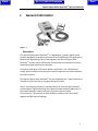
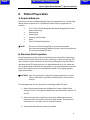
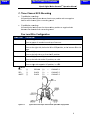
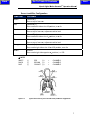
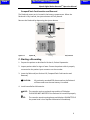
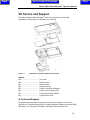
Go To Table Of Contents
Next
OPERATION / SERVICE MANUAL Part Number: 3‐100‐1045 Revision G
Next
Back
IQmark Digital Holter RecorderCF Operation Manual Table of Contents
A WORD OF THANKS ....................................................................................................................... II PRECAUTIONS ................................................................................................................................ III I. GENERAL INFORMATION ................................................................................................... 1 Description .................................................................................................................................................. 1 A. Key Components ........................................................................................................................ 2 Patient Event Button ................................................................................................................................... 2 Storage Media ............................................................................................................................................ 2 B. System Specifications ................................................................................................................. 3 II. A. B. C. PATIENT PREPARATION ..................................................................................................... 4 Required Materials .................................................................................................................... 4 Electrode Site Preparation ......................................................................................................... 4 Three Channel ECG Recording ................................................................................................... 6 Five Lead Wire Configuration ...................................................................................................................... 6 Seven Lead Wire Configuration ................................................................................................................... 7 III. A. B. RECORDER OPERATION ...................................................................................................... 8 Required Materials .................................................................................................................... 8 Recorder Set‐Up and Configuration ........................................................................................... 8 Patient Cable ............................................................................................................................................... 8 CompactFlash Card Insertion and Removal ................................................................................................ 9 Remove the flashcard by depressing the ejector button. ............................................................................ 9 C. D. Starting a Recording ................................................................................................................... 9 Early Termination of Recording ............................................................................................... 11 IV. TROUBLESHOOTING GUIDE .............................................................................................. 12 V. A. B. MAINTENANCE AND STORAGE ......................................................................................... 13 Preventative Inspection ........................................................................................................... 13 Cleaning the Recorder ............................................................................................................. 13 Cleaning the Carrying Case ....................................................................................................................... 13 Cleaning the Patient Cable ........................................................................................................................ 13 C. D. E. Bad Weather Conditions .......................................................................................................... 14 Storage ..................................................................................................................................... 14 Radio and Television Interference ........................................................................................... 14 VI. EMC REQUIREMENTS FOR THE IQMARK DIGITAL HOLTER RECORDERCF ............................. 15 VII. SERVICE AND SUPPORT ........................................................................................................... 19 A. Technical Support .................................................................................................................... 19 B. Limited Warranty ..................................................................................................................... 20 Return Materials Authorization (RMA) ..................................................................................................... 20 Shipping .................................................................................................................................................... 20 C. Safety and International Symbols ............................................................................................ 21 VIII. REORDERING SUPPLIES .................................................................................................... 22 i Go To Table Of Contents
Back
Next
IQmark Digital Holter RecorderCF Operation Manual A Word of Thanks
Thank you for your purchase of the IQmark Digital Holter RecorderCF. Midmark has used the latest microelectronic and computer software technology to develop a fast, efficient and accurate digital Holter system. We believe you will be pleased with the user‐friendly operation of our product and its results. As your partner in healthcare, we look forward to working with you in the coming years as we develop even more sophisticated diagnostic technology for the cardiopulmonary field. Your thoughts, questions and comments about our product are welcome. CAUTION: Federal Law restricts this device to sale by or on the order of a physician. Physician’s Responsibility The results provided by IQmark Digital Holter RecorderCF are for the exclusive use of licensed physicians or personnel under their direct supervision. It is the responsibility of the physician to ensure proper administration of the test, making a diagnosis, obtaining expert opinions on the results and instituting the correct treatment. Disclosures The information in this guide is subject to change without notice. Midmark shall not be liable for technical or editorial omissions made herein, nor for incidental or consequential damages resulting from the furnishing, performance or use of this guide. This document may contain proprietary information protected by copyright. No part of this document may be photocopied or reproduced in any form without prior written consent from Midmark. IQmark™ is a registered trademark of Midmark. ii Back
Go To Table Of Contents
Next
IQmark Digital Holter RecorderCF Operation Manual Precautions
Read the following to ensure the proper operation of the IQmark Digital Holter RecorderCF: 1.
Familiarize yourself thoroughly with the operational procedures of the IQmark Digital Holter RecorderCF prior to use. 2.
Disconnect the recorder from patients during defibrillation. 3.
The recorder is not designed for sterile use. 4.
The recorder is not intended for use with rechargeable batteries. 5.
Instrument maintenance: • Keep the recorder away from splashing water. • Do not store or use the recorder where humidity, ventilation, direct sunlight or air containing dust, salt or sulfur might affect it. • Prevent the recorder from slipping and protect it from the possibility of vibration, shock or drop; be particularly careful during transport. • Do not store or use the recorder in a chemical storage area, or where gas is generated. 6.
Preparation of the recorder prior to operation: • Verify proper recorder operation. • Check that cable connections are secure. 7.
Precautions while using the recorder: • Avoid activities that could affect the quality of recorded signals. Do not sleep under an electric blanket. • Patients should not shower, take baths, use hot tubs or perform similar activities while wearing the recorder. • Keep the recorder and electrode sites dry while in use. • Do not tamper with the recorder. Do not remove the flashcard or battery until the recording is complete. 8.
Precautions after using the recorder: • Remove the batteries and flashcard. • Download patient data to computer as soon as possible to preserve patient data. • Do not remove then reinstall batteries with the flashcard installed. Patient data will be lost. • Keep the recorder clean to ensure trouble‐free operation during next use. 9.
Perform routine inspection of the recorder and accessories. 10.
Do not make any modifications to the recorder. !DANGER: Possible explosion hazard if used in the presence of flammable anesthetics. CAUTION: Refer servicing to qualified service personnel. iii Go To Table Of Contents
Back
Next
IQmark Digital Holter RecorderCF Operation Manual I.
General Information
Figure 1‐1 The IQmark Digital Holter RecorderCF Description
The IQmark Digital Holter RecorderCF is a lightweight, compact, digital Holter recorder designed for reliability and ease of use in ambulatory ECG applications. Because the digital design has no moving parts, the IQmark Digital Holter RecorderCF records cleaner ECG quality and has lower maintenance cost when compared to tape‐based Holter recorders. A liquid crystal display (LCD) assists Holter technicians in the verification of proper patient hookup, eliminating the need for expensive test cable interfaces with EKG machines. The IQmark Digital Holter RecorderCF can be configured as a 7‐lead/3‐channel or 5‐lead/3‐channel recorder by changing the patient cable. Data is conveniently stored on a reusable flashcard, eliminating the need for cassette tapes. Digital technology also eliminates tape‐based variables such as tape‐head frequency, speed variations, distortion and tape brand inconsistencies. The removal of these variables produces more accurate ST segment and RR interval readings. 1 Go To Table Of Contents
Back
Next
IQmark Digital Holter RecorderCF Operation Manual A. Key Components
Figure 1‐2 Key components Patient Event Button
A momentary Event button is provided on the recorder as a convenient means of marking and storing event times. When Holter data is played back, ECG events are made available that correlate to the Event button being pressed. Storage Media
The IQmark Digital Holter RecorderCF utilizes a flashcard to store ECG data. The flashcard is reusable and, with proper care, should last for hundreds of recordings. The flashcard must have a memory capacity of at least 48MB. For suitable replacements or additional flashcards, please contact your Midmark sales rep or Customer Service. Always keep the flashcard away from moisture and inspect the pinholes for foreign matter prior to insertion. When preparing for a recording session, insert the flashcard before installing the battery; it is not recommended to install the flashcard after the battery is installed, as the access port is located in the battery compartment. 2 Go To Table Of Contents
Back
Next
IQmark Digital Holter RecorderCF Operation Manual B. System Specifications
IQmark Digital Holter RecorderCF Performance Specifications Category Specification Intended Use Provides 24‐hour Holter recordings which permit the detection of abnormalities in the transmission of cardiac impulses through the heart muscle; serves as an important aid in the diagnosis of heart ailments. Weight Dimensions Operating Temperature Non Operating Shock Operating Position Humidity Storage Media 4 ounces
4.46 x 2.75 x 1.02 (inches)
113 x 70 x 26 (mm) 0 to 60 degrees Celsius
1 Meter drop
Any orientation
10% to 95% (non‐condensing)
IDE/PCMCIA CompactFlash card Standard
Recording Time Channels Sample Rate Resolution Bandwidth Input range Battery (alkaline) Patient Input CMRR 24‐hours 3
128 samples per channel/sec
8 bits
0.05 to 60Hz 3dB 5.0 mV
2 AA, IEC‐LR6
5‐ or 7‐lead configuration
60 dB
PHYSICAL FUNCTIONAL PACE DETECTION SPECIFICATION (Serial Number 380000 or higher) Pulse Amplitude (at skin) Pulse Width (at skin) +/‐ 2 mV to +/‐ 500 mV
2ms to 0.1ms
3 Go To Table Of Contents
Back
Next
IQmark Digital Holter RecorderCF Operation Manual II.
Patient Preparation
A. Required Materials
Operators must have a Midmark Holter Patient Preparation Kit or a similar high quality Holter preparation kit. The Midmark Holter Patient Preparation Kit contains: •
5 or 7 silver chloride disposable electrodes designed for 24 hour Holter monitoring •
Abrasive pad •
Patient diary •
Isopropyl alcohol wipes •
Razor •
Two (2) AA alkaline batteries NOTE: Do not use 12‐lead resting ECG or stress‐test electrodes. We recommend using the Midmark Holter Patient Preparation Kit for consistent quality ECG data. B. Electrode Site Preparation
Careful preparation of the patient’s electrode sites is essential for obtaining an interference‐free ECG and accurate result, especially in Holter monitoring. The skin is naturally a poor conductor of electricity and frequently creates artifact that distorts the ECG signal due to dry or dead epidermal cells, oils, sweat and dirt. By performing methodical skin preparation, you greatly reduce the resistive barrier that causes muscle noise and baseline wander, ensuring high‐quality signal and test data. CAUTION: Poor site preparation, improper electrode placement or use of inferior electrodes may lead to unusable data or an inaccurate analysis. The following steps are very important in obtaining usable ECG data: 1. Select the electrode placement configuration from a reliable clinical reference source. Two typical configurations are illustrated in Figures 2‐2 and 2‐3. 2. Select electrode sites located over bony areas where reduced tissue movement will minimize the amount of signal artifact. Electrode sites should be over a rib rather than an intercostal space. 3. Shave electrode placement areas, as needed. 4 Go To Table Of Contents
Back
Next
IQmark Digital Holter RecorderCF Operation Manual 4.
5.
6.
7.
8.
Gently scrub the skin with an abrasive pad, lint‐free gauze pad or fine sandpaper enclosed in the preparation kit. This loosens and removes dead skin. Wipe the scrubbed area with a clean alcohol pad and ensure the entire electrode site is free of oil. Repeat for all sites. Allow these areas to air dry naturally before attaching electrodes. Follow the electrode manufacturer’s application instructions when applying snap leads to the electrodes. To simplify this process, first apply the lead wire snaps to the electrodes then apply the electrodes to the patient. Remove the backing from a pre‐gelled disposable electrode and place an electrode on each of the prepared electrode sites, make certain that the right colored lead is placed on the proper site. Ensure that the gel in the center of each electrode maintains contact with the prepared skin surface and the electrode is not wrinkled. Form a stress loop with each electrode lead, then tape the loop to the skin. This reduces artifacts caused by snap rotation when leads are pulled or tugged by normal patient movements. Electrodes Tape Figure 2‐1 Stress loops Examples of stress loops 5 Go To Table Of Contents
Back
Next
IQm
mark Digital H
Holter RecorrderCF Operaation Manuaal C. Thre
ee Channel ECG Recording
R
g
•
•
7‐lead
d Holter reco
ordings Utilize
e a bipolar leead system w
where theree is one posittive and onee negative lead for each chan
nnel, plus a recorder gro
ound. d Holter reco
ordings 5‐lead
Utilize
e a bipolar leead system tthat shares eeither positivve or negative leads betwe
een the chan
nnels and a rrecorder gro
ound. Five Lead Wire Config
guration
Leaad Color Placemen
nt Red Whiite Brow
wn Blacck Greeen Channel 1 (‐), Channel 2
2 (‐) Place at cen
nter of manu
ubrium and top of sternum. Channel 3 (‐) Place on the right side, below the V
V1 or V3R po
osition, at th
he bottom off the rib cage. Channel 1 (+) n. Place on the left side on a rib at thee V3 position
Channel 2 (+), Channel 3 (+) Place on the left side att the V5 position, on a riib. Ground Place on rigght side oppo
osite V5 possition, i.e. V5
5R. NOTE: RED (‐) RED (‐) WHITE (‐) Figure 2‐2 BROWN
BLACK
BLACK
(+) (+) (+) =
=
=
CHANNEL 1 CHANNEL 2 CHANNEL 3 Typical three channell five lead electrode placemeent configuratiion 6 Go To Table Of Contents
Back
Next
IQm
mark Digital H
Holter RecorrderCF Operaation Manuaal Seven Lead Wire Configu
uration
Leaad Color Placeme
ent Whiite Channel 1
1 (‐) Place at top of sternu
um. Channel 1
1 (+) Place on tthe left side at the V3 po
osition, on aa rib. Red Blacck Brow
wn Bluee Oran
nge Greeen Channel 2
2 (‐) Place at top of sternu
um, adjacentt to white lead. Channel 2
2 (+) Place on tthe left side at the V5 po
osition, on aa rib. Channel 3
3 (‐) Place at top of sternu
um, adjacentt to white lead Channel 3
3 (+) Place on tthe right side at the V1 o
or V3R posittion, on a rib
b. Ground Place on tthe right side opposite V
V5 position, i.e. V5R. NOTE: (‐) WHITE (‐) BLACK BLUE (‐) Figure 2‐3 RED
(+) BROWN (+) ORANGE (+) =
=
=
CHANNEEL 1 CHANNEEL 2 CHANNEEL 3 Typical three channel,
l, seven lead ellectrode placeement configurration 7 Go To Table Of Contents
Back
Next
IQmark Digital Holter RecorderCF Operation Manual III. Recorder Operation
A. Required Materials
•
•
•
•
•
One (1) Delkin® or one (1) Sandisk® CompactFlash memory card (64MB ‐ 1GB) Midmark Holter Patient Preparation Kit IQmark Digital Holter RecorderCF Patient cable Carrying case and belt B. Recorder Set-Up and Configuration
Patient Cable
1. Remove the color‐coded patient cable from the shipping package. 2. Attach cable to the patient cable connector on the recorder. a) Ensure proper alignment of the connector before tightening the cable to the recorder. b) Do not over‐tighten. Figure 3‐1 IQmark Digital Holter RecorderCF components Recorder input configuration is automatically selected by the attachment of the appropriate patient cable. The options are 5‐lead/3‐channel or 7‐lead/3‐channel. Please see Figures 2‐2 and 2‐3 for proper cable selection. 8 Go To Table Of Contents
Back
Next
IQmark Digital Holter RecorderCF Operation Manual CompactFlash Card Insertion and Removal
The flashcard access port is located in the battery compartment. When the flashcard is fully inserted, the ejector button will fully extend. Remove the flashcard by depressing the ejector button. Figure 3‐2 IQmark Digital Holter RecorderCF CompactFlash Card insertion/removal C. Starting a Recording
1. Prepare the patient as described in Section II, Patient Preparation. 2. Inspect patient cable for signs of wear. Ensure the patient cable is properly connected to the patient input connector on the recorder. 3. Insert the flashcard (see Section III‐B, CompactFlash Card Insertion and Removal). All previously recorded ECG data stored on the flashcard CAUTION: will be erased once the new battery is installed. 4. Install new alkaline AA batteries. NOTE: The recorder emits a continual tone and the LCD displays FLASHCARD NOT INSERTED if the flashcard is inserted improperly. NOTE: The recorder sounds warning beeps and displays LOW BATTERY if the power level is low. Replace the batteries immediately. 9 Go To Table Of Contents
Back
Next
IQmark Digital Holter RecorderCF Operation Manual 5.
6.
7.
8.
9.
Recorder should beep once and the LCD will activate. If not, verify if: • The above sequence was followed • The batteries were correctly installed • The recorder is operating properly To verify connection, the recorder displays the three channels of the patient’s ECG on the LCD readout. Press the event button to display an enlarged single‐channel display or to rotate through the channels: All, 1, 2, 3. The recorder will automatically start recording in approximately eight (8) minutes. If you need more time to complete or correct the patient connection, remove one of the batteries and replace it when you are ready to continue. NOTE: After a good connection has been verified, the ECG recording mode may be started immediately by pressing and holding the event button for five seconds or until the ECG display turns off. Document the recording start time in the patient diary, preferably using the patient’s watch for the correct time. Otherwise, use your own watch or a wall clock. NOTE: The recorder will always report a start time of 00:00:00. The Holter scanning technician uses the start time that is entered in the diary as the start time for the recording. Before the patient is released, verify that s/he understands the following: • How to use the event button and patient diary (see Section I‐A, Patient Event Button for more information). • Keep the recorder away from moisture. • Do not tamper with the recorder or remove the flashcard or batteries. • Avoid touching the electrode sites. • Do not to use an electric blanket while using the recorder. • Avoid environments that have strong electrical or electromagnetic interference. See Section VI, EMC Requirements for the IQmark Digital Holter RecorderCF. Place the recorder into the pouch and secure the pouch to the patient’s belt via use the belt provided or through the loop on the back of the pouch. 10 Back
Go To Table Of Contents
Next
IQmark Digital Holter RecorderCF Operation Manual D. Early Termination of Recording
The recorder automatically terminates each recording after 24‐hours. To terminate the recording sooner, remove the battery and flashcard. A loss of up to six (6) minutes of data is normal if the recording is terminated early. CAUTION: Removal of the flashcard during the first ten (10) minutes of recording will result in a flashcard with no data stored on it. 11 Go To Table Of Contents
Back
Next
IQmark Digital Holter RecorderCF Operation Manual IV. Troubleshooting Guide
This Troubleshooting Guide provides a list of solutions and recommendations to potential problems you may encounter while using the IQmark Digital Holter RecorderCF. Before calling Midmark Customer Service, please refer to the following table for help. Troubleshooting Guide
Error Message/Problem No tone or display •
following initial battery •
installation Potential Solution/Recommendation Batteries are very weak Batteries are incorrectly installed LCD displays ‘FLASHCARD Incomplete flashcard installation: NOT INSERTED’ and the 1. Remove batteries unit emits a continuous 2. Install flashcard tone following battery 3. Reinstall batteries installation. Unit emits a continuous •
two‐tone alarm and •
displays ‘FLASHCARD DID NOT RESET.’ Non‐supported flashcard installed The flashcard did not initialize correctly, reinstall batteries Unit emits a continuous single‐tone beeping alarm •
The flashcard did not initialize correctly, reinstall batteries One or more channel has low amplitude, excessive artifact or a wandering baseline. ECG data is not observed after recording session is complete. •
•
Bad lead wire set Poor connection •
Poor batteries •
Unit operated for less than ten minutes prior to battery or flashcard removal •
The flashcard or recorder has malfunctioned 12 Go To Table Of Contents
Back
Next
IQmark Digital Holter RecorderCF Operation Manual V.
Maintenance and Storage
A. Preventative Inspection
Perform a periodic preventative inspection prior to each use of the recorder. This is done to verify there is no visible damage to the recorder that may cause it to malfunction. Visual inspection should include the inspection of the Holter recorder and all cables for signs of damage and deterioration, including but not limited to: cracks, cuts, discoloration and oxidation. If a cable or other accessory exhibits any of these symptoms replace it immediately prior to use of the recorder. B. Cleaning the Recorder
CAUTION Do not use aromatic hydrocarbons, rubbing alcohol or chlorinated solvents for cleaning the Holter recorder. Do not use alcohol or acetone on lead wires or cables, since they could stiffen and crack the insulating plastic. Clean the outside of the Holter recorder with a soft cloth dampened with a mild household cleaner. Avoid using excessive amounts of solution, which may infiltrate the connectors, battery compartments or recording module. Verify that all equipment, including accessories, are completely dry before using. CAUTION: Do not immerse the Holter recorder in any kind of liquid. Cleaning the Carrying Case
If the carrying case becomes soiled, the operator has the option to purchase a new pouch or wash the existing one in cold water with a mild detergent. Cleaning the Patient Cable
Clean the cables following a hospital approved cleaning procedure, such as those recommended by AAMI or AORN. Wiping the cables with a solution of soap and water followed by a rinse with water is a simple yet effective method for cleaning the cables. Do not immerse the cables in water. The cables may be disinfected by wiping with a 1:10 solution of chlorine bleach and water, or a 2% gluteraldehyde solution such as Cidex ™. The cables should then be rinsed and wiped dry. 13 Go To Table Of Contents
Back
Next
IQmark Digital Holter RecorderCF Operation Manual NOTE: Worn or damaged patient cables are the most common cause of poor quality recordings. Successive poor ECG tracings may indicate the patient cable needs to be replaced. C. Bad Weather Conditions
In rain or snow conditions, instruct patients to protect the recorder from the elements by wearing the recorder inside a coat. D. Storage
To prevent damage to the recorder due to battery leakage or oxidation, the batteries should be removed whenever the recorder is not in use or prior to storage for a long period of time. Avoid extreme humidity and heat during storage. Although the flashcard is very durable, it should be stored within the recorder or its original case when not in use. This reduces the possibility of dust or moisture damaging the flashcard. E. Radio and Television Interference
This equipment generates and uses radio frequency energy. If not installed and used properly, in strict accordance with the manufacturer’s instructions, it may cause interference with radio and television reception. This equipment has been tested and proven to be in compliance with standards for medical devices in accordance with the IEC 601‐1 rules, which are designed to provide reasonable protection against such interference in a medical or hospital environment. See Section VI, EMC Requirements for the IQmark Digital Holter RecorderCF for requirements when operating the recorder. 14 Go To Table Of Contents
Back
Next
IQmark Digital Holter RecorderCF Operation Manual VI. EMC Requirements for the IQmark Digital
Holter RecorderCF
Medical electrical equipment needs special precautions regarding EMC and needs to be installed and put into service according to the EMC information provided in this Addendum. Portable and mobile RF communications equipment can affect the operation of medical electrical equipment. The CF
IQmark Digital Holter Recorder is medical electrical equipment. The following is a list of the lead wires and CompactFlash cards that are used as part of the IQmark Digital Holter CF
Recorder that comply with sections 36.201 and 36.202 of the EMC Standard IEC60601‐1‐2 (E). Electromagnetic compatibility testing has not been conducted using lead wires longer than 40 inches (101.6 cm). Lead Wires 5‐Lead 3‐Channel Lead Wires 7‐Lead 3‐Channel Lead Wires Memory Cards SanDisk CompactFlash card: standard length, Type I CompactFlash cards conforming to CompactFlash Specification 1.4 as issued by the CompactFlash Association. Use of lead wires, CompactFlash cards, or accessories other than those specified, with the exception of lead wires, CF CompactFlash cards, and accessories sold by the manufacturer of the IQmark Digital Holter Recorder as replacement parts for internal components, may result in increased EMISSIONS or decreased IMMUNITY of the CF IQmark Digital Holter Recorder . CAUTION: CF
THE IQMARK DIGITAL HOLTER RECORDER SHOULD NOT BE USED ADJACENT TO OR STACKED WITH OTHER EQUIPMENT. IF ADJACENT OR STACKED USE IS NECESSARY, THE IQMARK DIGITAL HOLTER CF
RECORDER SHOULD BE OBSERVED TO VERIFY NORMAL OPERATION IN THE CONFIGURATION IN WHICH IT WILL BE USED. Guidance and manufacturer's declaration ‐ electromagnetic emissions
CF
The IQmark Digital Holter Recorder is intended for use in the electromagnetic environment specified below. The CF
customer or the user of the IQmark Digital Holter Recorder should assure that it is used in such an environment. Emissions test Compliance
RF emissions CISPR11 Group 1
RF emissions CISPR11 Class B
Harmonic emissions CISPR11 N/A Voltage fluctuations/ flicker emissions IEC 61000‐3‐3 N/A Electromagnetic environment ‐ guidance CF
The IQmark Digital Holter Recorder uses RF energy only for its internal function. Therefore, its RF emissions are very low and are not likely to cause any interference in nearby electronic equipment. CF
The IQmark Digital Holter Recorder is suitable for use in all establishments, including domestic establishments and those directly connected to the public low‐voltage power supply network that supplies buildings used for domestic purposes. 15 Go To Table Of Contents
Back
Next
IQmark Digital Holter RecorderCF Operation Manual Guidance and manufacturer's declaration ‐ electromagnetic immunity
CF
The IQmark Digital Holter Recorder is intended for use in the electromagnetic environment specified below. The CF
customer or the user of the IQmark Digital Holter Recorder should assure that it is used in such an environment. Immunity test IEC 60601 test level Compliance level
Electromagnetic environment ‐
guidance Electrostatic discharge (ESD) IEC 61000‐4‐2 ±6 kV contact
±8 kV air ±6 kV contact
±8 kV air Floors should be wood, concrete, or ceramic tile. If floors are covered with synthetic material, the relative humidity should be at least 30 %. Electrical fast transient/burst IEC 61000‐4‐4 ±2 kV for power supply
lines ±1 kV for input/output lines N/A
Battery‐powered device Surge IEC 61000‐4‐5 ±1 kV for differential mode ±2 kV common mode N/A
Battery‐powered device Voltage dips, short interruptions, and voltage variations on power supply input lines IEC 61000‐4‐11 <5 % UT (>95 % dip in UT) for 0.5 cycle 40 % UT (60 % dip in UT) for 5 cycles 70 % UT (30 % dip in UT) for 25 cycles <5 % UT (>95 % dip in UT) for 5 sec N/A
Battery‐powered device Power frequency (50/60 Hz) magnetic field IEC 61000‐4‐8 3 A/m 3 A/m
Power frequency magnetic fields should be at levels characteristic of a typical location in a typical commercial or hospital environment. NOTE—UT is the a.c. mains voltage prior to application of the test level. 16 Go To Table Of Contents
Back
Next
IQmark Digital Holter RecorderCF Operation Manual Guidance and manufacturer's declaration ‐ electromagnetic immunity
CF
The IQmark Digital Holter Recorder is intended for use in the electromagnetic environment specified below. The CF
customer or the user of the IQmark Digital Holter Recorder should assure that it is used in such an environment. Immunity test IEC 60601 test level
Conducted RF IEC 61000‐4‐6 Radiated RF IEC 6100‐4‐3 3 Vrms 150 kHz to 80 MHz 3 V/m 80 MHz to 2.5 GHz Compliance level
[V1] V N/A 3 V/m Electromagnetic environment ‐ guidance Portable and mobile RF communications equipment should be used no closer to any part of the IQmark CF
Digital Holter Recorder , including cables, than the recommended separation distance calculated from the equation applicable to the frequency of the transmitter. Recommended separation distance Not Applicable d = 1.2 √P 80 MHz to 800 MHz d = 2.3 √P 800 MHz to 2.5 GHz where P is the maximum output power rating of the transmitter in watts (W) according to the transmitter manufacturer and d is the recommended separation distance in meters (m). Field strengths from fixed RF transmitters, as a
determined by an electromagnetic site survey, should be less than the compliance level in each frequency .b
range Interference may occur in the vicinity of equipment marked with the following symbol: of equipment marked with the following symbol: NOTE 1: At 80 MHz and 800 MHz, the higher frequency range applies.
NOTE 2: These guidelines may not apply in all situations. Electromagnetic propagation is affected by absorption and reflection from structures, objects, and people. a
Field strengths from fixed transmitters, such as base stations for radio (cellular/cordless) telephones and land mobile radios, amateur radio, AM and FM radio broadcast, and TV broadcast cannot be predicted theoretically with accuracy. To assess the electromagnetic environment due to fixed RF transmitters, an electromagnetic site survey should be CF
considered. If the measured field strength in the location in which the IQmark Digital Holter Recorder is used exceeds CF
the applicable RF compliance level above, the IQmark Digital Holter Recorder should be observed to verify normal operation. If abnormal performance is observed, additional measures may be necessary, such as re‐orienting or CF
relocating the IQmark Digital Holter Recorder b
Over the frequency range 150 kHz to 80 MHz, field strengths should be less than [V1] V/m. 17 Go To Table Of Contents
Back
Next
IQmark Digital Holter RecorderCF Operation Manual Recommended separation distances between portable and mobile RF communications equipment and the IQmark CF
Digital Holter Recorder CF
The IQmark Digital Holter Recorder is intended for use in an electromagnetic environment in which radiated RF CF
disturbances are controlled. The customer or the user of the IQmark Digital Holter Recorder can help prevent electromagnetic interference by maintaining a minimum distance between portable and mobile RF communications CF
equipment (transmitters) and the IQmark Digital Holter Recorder as recommended below, according to the maximum output power of the communications equipment.
Separation distance according to frequency of transmitter m Rated maximum output power of transmitter W 0.01 0.1 1 10 100 150 kHz to 80 MHz
N/A
N/A
N/A
N/A
N/A
80 MHz to 800 MHz
800 MHz to 2.5 GHz
d = 1.2 √P d = 2.3 √P 0.12 0.23 0.38 0.73 1.2 2.3 3.8 7.3 12 23 For transmitters rated at a maximum output power not listed above, the recommended separation distance d in meters (m) can be estimated using the equation applicable to the frequency of the transmitter, where P is the maximum output power rating of the transmitter in watts (W) according to the transmitter manufacturer. NOTE 1: At 80 MHz and 800 MHz, the separation distance for the higher frequency range applies. NOTE 2: These guidelines may not apply in all situations. Electromagnetic propagation is affected by absorption and reflection from structures, objects, and people. 18 Go To Table Of Contents
Back
Next
IQmark Digital Holter RecorderCF Operation Manual VII. Service and Support
The IQmark Digital Holter RecorderCF does not contain user serviceable components. Please return to Midmark for servicing. Figure 7‐1 Expanded View of IQmark Digital Holter RecorderCF Legend
01)...................................... 02)...................................... 03)...................................... 04)...................................... 05)...................................... 06)...................................... 07)...................................... 08)...................................... Top cover Bottom cover Battery cover Battery clips (4) Patient connector bulkhead Liquid crystal display (LCD) Printed circuit board (PCB) CompactFlash card A. Technical Support
For questions pertaining to this product and technical support, consult this manual, the Troubleshooting Guide or contact Midmark Support Services at (800) 624‐8950, ext. 2 between 6:30 AM to 4:30 PM, Pacific Standard Time. 19 Back
Go To Table Of Contents
Next
IQmark Digital Holter RecorderCF Operation Manual B. Limited Warranty
All Midmark digital module products are warranted to be free from manufacturing and material defects for 12 months from the date of purchase; CompactFlash cards are warranted for 90 days and Holter patient cables are warranted for 30 days. Any misuse or abuse of a Midmark product voids all applicable warranties. A full copy of the Midmark limited warranty is found on the warranty registration documentation provided with this product. Return Materials Authorization (RMA)
To return any product for any reason, a Return Materials Authorization (RMA) number must be obtained from a Midmark Support Services representative. The number must be referenced on the package(s) containing the items to be returned, and in any correspondence regarding the return. Shipping
Before shipping any unit to Midmark, be certain that an RMA number has been issued and that all guidelines regarding this authorization are followed. We highly recommend that you follow all guidelines for the shipment of medical products set forth by your shipping company. If you have a question regarding the appropriate shipment method, please feel free to ask when calling for your RMA number. It is ultimately the responsibility of the customer when shipping a product to ensure that all packages and their contents arrive at Midmark safely. MIDMARK WILL NOT ASSUME RESPONSIBILITY FOR DAMAGE INCURRED BY IMPROPER PACKAGING, SHIPMENT OR PRODUCT USE. SUCH ACTIONS VOID ALL APPLICABLE WARRANTIES. Midmark Diagnostics Group 1125 West 190th Street Gardena, CA 90248 Tel: (310) 516‐6050 USA: (800) 624‐8950, ext. 2 Fax:(310) 516‐6517 20 Go To Table Of Contents
Back
Next
IQmark Digital Holter RecorderCF Operation Manual C. Safety and International Symbols
The following symbols are used on the IQmark Digital Holter RecorderCF product. Refer to this directory for details concerning symbols used on the instrument. Symbol !
Description ATTENTION Refer to manual for instructions Year of manufacture Battery Orientation This device uses 2 AA alkaline batteries. The icon indicates the proper orientation of batteries to be installed. DC Voltage This device uses 3‐Volt DC power and consumes 20mA (nominal) when in use. CE Mark Equipment displaying this symbol has passed specific safety tests and adheres to international quality standards established by the European Commission. Device is compliant with IEC 60601‐1 as a Type BF, internally powered device. ¼ [ “Ordinary” enclosure IPX0: Keep the instrument away from splashing water. Conforms to UL Std. 2601‐1 and Certified to CAN/CSA Std. C22.2 No. 601.1. 21 Back
Go To Table Of Contents
Next
IQmark Digital Holter RecorderCF Operation Manual VIII. Reordering Supplies
Contact your local distributor for reordering supplies for your Holter monitoring. Midmark Part Number Description 1‐370‐0002 CompactFlash card 2‐100‐0080 Prep Kit – IQmark Holter, 5‐lead, 2AA’s (each) 2‐100‐0081 Prep Kit – IQmark Holter, 5‐lead, 2AA’s (case – 30 kits) 2‐100‐0090 Prep Kit – IQmark Holter, 7‐lead, 2AA’s (each) 2‐100‐0091 Prep Kit – IQmark Holter, 7‐lead, 2AA’s (case – 30 kits) 3‐370‐0001 Lead Wire, 5‐lead, IQmark Digital RecorderCF 3‐370‐0002 Lead Wire, 7‐lead, IQmark Digital RecorderCF 3‐370‐0003 Pouch with Belt for IQmark Digital RecorderCF 22 Go To Table Of Contents
Back
Midmark Diagnostics Group 1125 W. 190th Street Gardena, California 90248 Support Services: 1‐800‐624‐8950, Option 2 www.midmark.com ©Midmark Corporation 2009