1
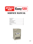
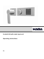
Combi B 30 with metal input unit Operating Instructions EN Operating instructions 82132/3xxx CB 30 Table of contents 1 Important notes ................................................................................................................................................28 2 Glossary of abbreviations and terms .............................................................................................................29 3 The icons used in the instructions .................................................................................................................30 4 Lock system: Input unit and lock ...................................................................................................................31 4.1 Operating elements of the input unit ....................................................................................................................... 31 4.2 Lock housing and interfaces .................................................................................................................................... 31 5 Overview of authorizations .............................................................................................................................32 6 Overview of the programming commands ....................................................................................................32 7 Overview of the possible signals ...................................................................................................................33 8 Start-up of the lock ..........................................................................................................................................34 9 8.1 Opening with assembler code.................................................................................................................................. 34 8.2 Activating master ...................................................................................................................................................... 34 Programming functions for the master .........................................................................................................34 9.1 Changing master code (P) ........................................................................................................................................ 35 9.2 Programming functions for further codes (P3-P6) ................................................................................................. 35 9.2.1 Activating user codes or courier codes (P3) ....................................................................................................... 35 9.2.2 Blocking the user codes or courier codes (P4) ................................................................................................... 36 9.2.3 Releasing the user codes or courier codes (P4) ................................................................................................. 36 9.2.4 Deleting the user codes or courier codes (P5).................................................................................................... 36 9.2.5 Code status query (P6) ....................................................................................................................................... 37 9.3 9.3.1 Activating opening delay and opening standby time (P2) ................................................................................... 37 9.3.2 Deactivating opening delay and opening standby time (P2) ............................................................................... 37 9.4 Activating the double code (P7) .......................................................................................................................... 38 9.4.2 Deactivating double code (P7)............................................................................................................................ 38 Programming silent alarm (P8) ................................................................................................................................ 39 9.5.1 Activating the silent alarm (P8) ........................................................................................................................... 39 9.5.2 Deactivating silent alarm (P8) ............................................................................................................................. 39 9.6 11 Programming the double code (P7) ......................................................................................................................... 38 9.4.1 9.5 10 Programming opening delay and opening standby time (P2) ............................................................................... 37 Acknowledging take-off contact message (P9) ...................................................................................................... 39 Lock functions for all users ............................................................................................................................40 10.1 Opening the lock without programmed OD/OST .................................................................................................... 40 10.2 Opening the lock with programmed OD/OST.......................................................................................................... 40 10.3 Opening with double code ....................................................................................................................................... 41 10.4 Opening with silent alarm ......................................................................................................................................... 41 10.5 Guard time (3 or more incorrect code inputs) ........................................................................................................ 42 10.6 Closing the lock......................................................................................................................................................... 42 10.7 Changing codes (P)................................................................................................................................................... 42 10.8 Opening with activated additional functions .......................................................................................................... 43 Key functions ...................................................................................................................................................43 11.1 Key opening ............................................................................................................................................................... 43 11.2 Closing using the key ............................................................................................................................................... 44 Version 2013-08-10 Page 26 of 48 Operating instructions 82132/3XXX - Combi B 30 12 13 11.3 Changing master code using the key (P) ................................................................................................................ 44 11.4 Resetting the lock (P0).............................................................................................................................................. 44 11.5 Reconfiguration of the lock after opening by means of the key using software ................................................. 45 Further special functions ................................................................................................................................45 12.1 Connection to the PC software ................................................................................................................................ 45 12.2 Additional functions via the signal input ................................................................................................................ 45 12.3 Additional functions via the signal outputs ............................................................................................................ 45 Power supply ....................................................................................................................................................45 13.1 Undervoltage indication ........................................................................................................................................... 46 13.2 Battery replacement .................................................................................................................................................. 46 13.3 Permanent power supply.......................................................................................................................................... 47 14 Service ..............................................................................................................................................................47 15 Notes .................................................................................................................................................................48 List of tables Table 1: Icons ............................................................................................................................................................................... 30 Table 2: Authorizations ................................................................................................................................................................. 32 Table 3: Programming commands ................................................................................................................................................ 32 Table 4: Messages from the lock, terms see chapter 2, icons see chapter .................................................................................. 33 Table 5: Opening with assembler code ......................................................................................................................................... 34 Table 6: Activating master ............................................................................................................................................................ 34 Table 7: Changing master code .................................................................................................................................................... 35 Table 8: Activating code ............................................................................................................................................................... 35 Table 9: Blocking the code............................................................................................................................................................ 36 Table 10: Releasing code ............................................................................................................................................................. 36 Table 11: Deleting code ................................................................................................................................................................ 36 Table 12: Requesting code status ................................................................................................................................................ 37 Table 13: Code status messages ................................................................................................................................................. 37 Table 14: Programming opening delay and opening standby time ............................................................................................... 37 Table 15: Deleting opening delay and opening standby time........................................................................................................ 38 Table 16: Activating double code .................................................................................................................................................. 38 Table 17: Deactivating double code .............................................................................................................................................. 38 Table 18: Activating silent alarm ................................................................................................................................................... 39 Table 19: Deactivating silent alarm ............................................................................................................................................... 39 Table 20: Acknowledging the take-off contact message ............................................................................................................... 40 Table 21: Opening with master or user code ................................................................................................................................ 40 Table 22: Opening with programmed OD/OST ............................................................................................................................. 40 Table 23: Opening with double code ............................................................................................................................................ 41 Table 24: Alarm code examples ................................................................................................................................................... 41 Table 25: Opening with alarm code .............................................................................................................................................. 42 Table 26: Changing code .............................................................................................................................................................. 42 Table 27: Changing master code using the key ............................................................................................................................ 44 Table 28: Resetting the lock ......................................................................................................................................................... 45 List of figures Figure 1: Input unit ........................................................................................................................................................................ 31 Figure 2: Mini-USB socket ............................................................................................................................................................ 31 Figure 3: Lock housing ................................................................................................................................................................. 31 Figure 4: Connections at the lock housing .................................................................................................................................... 31 Figure 5: Opening with the key ..................................................................................................................................................... 43 Figure 6: Battery replacement....................................................................................................................................................... 46 Figure 7: Label with the production data in the input unit .............................................................................................................. 47 Figure 8: Information on the label ................................................................................................................................................. 47 Version 2013-08-10 Page 27 of 48 Operating instructions 82132/3xxx CB 30 1 Important notes Before the start-up of the lock read these operating instructions carefully and observe the following notes: The enclosed inspection key allows full access to the lock and its configurations even in case of code loss. Thus, it is at the highest hierarchy level of the lock. Therefore, it must be stored in a safe place, but not in the secure storage unit. For security reasons programming and battery replacement should always be performed and then tested with the secure storage unit open. Every correct key stroke recognized by the lock is confirmed by an acoustic signal. You have max. 10 sec. for each individual key stroke. If no key is pressed during these 10 seconds, the electronics shuts down automatically. Uncompleted operations must be restarted after that. The only exceptions to this are the code status query and the programming mode with 30 seconds response time until automatic shutdown. Code inputs resp. all further functions (e.g. programming operations) can be cancelled until the last key stroke by pressing the key twice. Do not use for your code personal or similar known data which are easy to find out. If the set code(s) is(are) not available, the lock can be opened or reset using the enclosed inspection key. The lock is designed for use in the temperature range from +10° C to +50° C and with humidity of 30% to 80% (noncondensing). The lock must never be greased with or contact other lubricants or aggressive liquids, it must be cleaned only with a moist cloth only (no aggressive cleaning agents). Never open the lock housing. Dismount the fitting only for battery replacement and perform it strictly according to the specifications of these operating instructions. Avoid touching electronic components. Otherwise, you endanger the functions of the lock and loose the right for the warranty claims. During start-up the serial number of the input unit is saved in the audit memory of the lock. Replacement of the input unit is also registered by means of an entry in the audit memory of the lock. For every description of operation or programming processes hereafter it is assumed that the lock and the input unit are in the basic state. Basic state means that the lock is closed (the bolt lock is extended) and the lock electronics is switched off. If you are not sure, whether the lock is closed, check if the rotary knob can be turned counterclockwise. To ensure that the lock is not in a running programming process, you can press the key twice to cancel it. Upon delivery the lock is set by Kaba Mauer GmbH to the assembler coder "1". For security reasons activate the master code with your individual code immediately in order to deactivate the assembler code. The assembler code is meant only for lock mounting, it is not suitable for further permanent use. Furthermore, the lock has the option for partial or full start-up by the safe manufacturer or distributor: For a partial start-up basic configurations are loaded to the lock without activation of the master code. So, the lock still opens with "1". All configurations performed previously using software are immediately valid only after activation of the master code (start-up according to 8.2). For full start-up the lock has already been provided with a master code and further settings if necessary. In both cases the set basic configuration is communicated separately by the safe manufacturer or distributor. If a full start-up has been performed and, thus, a master code preset as delivery code, the safe manufacturer or distributor can save it additionally in the following hatched text box. All pre-configured codes have to be changed by the end user immediately after start-up. The master code set by the distributor resp. safe manufacturer (delivery code): 00______ _ _ _ Note for the end user: Change all delivery codes immediately! If further codes have been pre-assigned, see separate information of the safe distributor resp. manufacturer. Stamp of the safe manufacturer/distributor Version 2013-08-10 Page 28 of 48 Operating instructions 82132/3XXX - Combi B 30 2 Glossary of abbreviations and terms - Code: - ID: PIN: - Operator: - Master code: - User code: Courier code: - Assembler code: OD: OST: - Guard time: - Double code: Silent alarm: - EMA: - Undervoltage indication: - AHK: - Audit: - Reset: - Inspection key: Numerical sequence of 8 digits for identification of the operator consisting of ID and PIN. fixed 2-digit operator number. freely selectable 6-digit combination (Notice, do not use personal data such as for example date of birth). the master, user and courier are operators of the lock – each operator of the lock has an individual ID (00, 01..30; 95) assigned. ID 00; the highest code of the code hierarchy, can open the lock, change its own code, it is required for almost all programming functions of the lock. Can also perform programming functions independently in the double-code mode. ID 01 to 30, can open the lock and change its own code. ID 95, can open the lock without waiting for an opening delay which might be programmed and change its own code. has no ID, can open the lock during mounting at the factory. adjustable time which has to pass before the lock can be opened. Opening standby time: adjustable time which starts after the opening delay; The lock can be opened during the opening standby time. After entering the code 3 times incorrectly the guard time is activated, no inputs are possible at the lock during the guard time. Two different valid codes are required to open the lock. If the lock is connected to an external alarm system (intruder detection system) and this function is activated at the lock, a silent duress alarm can be triggered (not perceivable for the intruder). Intruder detection system: external alarm system for evaluation / forwarding of the duress alarm or secured permanent power supply (not included in the scope of delivery). indicates that the batteries are low and must be replaced as soon as possible in order to ensure secure function of the lock. Take-off contact: A contact in the input unit which detects whether the input unit has been opened (e.g. for battery replacement). All relevant events (opening, closing, programming etc.) are saved in the audit memory (approx. 200 events) of the lock. If the memory is full, the oldest entry is overwritten automatically. The audit can be read out using software. Reset of the lock to the delivery state, only the master code and audit remain unchanged. The inspection key can open the lock any time mechanically independent of the electronics. Opening by means of the key does not have any OD or guard time. The inspection key can also be used to assign a new master code and reset the complete lock. Reconfiguration of the lock can be implemented using the inspection key and software without knowing or changing the master code. Therefore, the inspection key is positioned higher in the code structure than the master code and must be stored in a safe place (not in a secure storage unit). Version 2013-08-10 Page 29 of 48 Operating instructions 82132/3xxx CB 30 3 The icons used in the instructions Icon Meaning Warning Important Note Icon for the 2-digit code ID (also refer to chapter 2) oder Icon for individual number keys for the code input Action performed Action not performed Rotate the actuating knob through 90° clockwise. Rotate the actuating knob through 90° counterclockwise. Short signal LED green Continuous signal LED green LED green off Short signal LED red Continuous signal LED red LED red off Buzzer signal Table 1: Icons Version 2013-08-10 Page 30 of 48 Operating instructions 82132/3XXX - Combi B 30 4 Lock system: Input unit and lock The entire lock system consists of a visible input unit and the lock installed in the secure storage unit. All programmed codes and functions are saved only in the lock and, thus, in the secured area. 4.1 Operating elements of the input unit Actuating knob Keypad Keypad: 1 red and 1 green LED Numeric keys P key Enter key Figure 1: Input unit 4.2 Figure 2: Mini-USB socket Special interface, only in connection with original Kaba Mauer CB30 Use PC cable! Lock housing and interfaces Connection to further components (e.g. EMA) Power supply Figure 3: Lock housing Connection to the input unit Figure 4: Connections at the lock housing Version 2013-08-10 Page 31 of 48 Operating instructions 82132/3xxx CB 30 5 Overview of authorizations The authorizations of individual operators are as follows: Operator ID - Code designation Inspection key Authorization - 00 Master code 01..30 User codes 95 Courier code - Assembler code - Opening without OD/OST and without guard time Assigning of a new master code Resetting the lock Changing the lock configurations using software without knowing the master code or changing it. Opening, if necessary, with silent alarm Changing of the own code Activating, blocking, releasing, deleting user and courier, with activated double code as well Activating / deactivating double code Programming / deleting OD/OST Neutralising the take-off contact Reading out audit Activating, deactivating silent alarm Access via PC software Opening, if necessary, with silent alarm Changing of the own code Opening without OD/OST, if necessary, with silent alarm Changing of the own code Opening Valid only until the real start-up of the lock, NOT A REAL CODE, not suitable for permanent use Table 2: Authorizations 6 Overview of the programming commands Action Changing own code Reading out audit Activating + deactivating OD/OST Activating user Blocking + releasing user Deleting user Code status query Activating + deactivating double code Activating + deactivating silent alarm Acknowledging the take-off contact message Resetting the lock Reassignment of the master code Table 3: Programming commands Version 2013-08-10 Page 32 of 48 Command Authorization P each P1 P2 P3 P4 Master P5 P6 P7 P8 P9 P0 Key P Operating instructions 82132/3XXX - Combi B 30 7 Overview of the possible signals Event When Pressing the key (e.g. code input) Code valid (code-correct message) Correct input With every key stroke 1x After pressing Enter 2x and 2 x 3x and 3 x 1x and 1 x 1x and 1 x Error message (e.g. code invalid) Recurring input (e.g. code confirmation) not matching Cancelation (manual cancelation with Signal After pressing or Enter time-controlled cancelation if there is no input) Take-off contact has been activated Guard time Double code; input of the second code is expected OD OST Undervoltage Programming mode Remote disable activated, no opening possible Hardware error. Contact the Service. 3 x after pressing Enter Permanentl y after pressing Enter Permanentl y after pressing Enter Permanentl y after pressing Enter Permanentl y after pressing Enter After pressing Enter Permanentl y after pressing Enter , then 1x , then 0.5 s break 1x , then 2 s break 1x , then 5 s break 1x and 1 x break , then 5 s 10 x 1x and With every key stroke 1x After pressing Enter 3s and 3 s 1x and 1 x 1x ,1x 1x and 1 x Code status messages Code active Code active but blocked After pressing Enter Code deleted or inactive and 1 x Table 4: Messages from the lock, terms see chapter 2, icons see chapter Version 2013-08-10 Page 33 of 48 Operating instructions 82132/3xxx CB 30 8 Start-up of the lock The lock installation as well as cabling and the first battery installation are described in the installation manual. As long as the lock system has not been put into operation, it can be opened using the assembler code. The assembler code is intended for lock mounting at the factory and not for further permanent use. For correct start-up of the lock the master code must be activated correctly according to chapter 8.2, this makes the assembler code invalid. If the start-up or partial start-up has already been performed by the safe manufacturer or distributor, the corresponding information is specified in its manuals/notes. Furthermore, the safe manufacturer or distributor can document the set master code in this manual. For this information refer to the field highlighted in gray in chapter 1 page 28, "Master code set by the distributor resp. safe manufacturer". 8.1 Opening with assembler code Description 1. Press and 2x 2x 3x 3x Turn the actuating knob within 4 seconds through 90° clockwise to the stop . Then open the storage unit. Table 5: Opening with assembler code 2. As long as the assembler code is used for opening (master is not activated yet), there is no guard time for incorrect code inputs according to chapter 10.5 and no take-off contact signal message according to either. 8.2 Activating master Now activate the master with the storage unit open (to have every time access to the storage unit and the lock). Description 1. Press and the new master code 2. Enter (00 = ID, X = freely selected 6-digit combination [0..9]) 3. Confirm the new master code with and and 2x 2x 3x 3x 2x 3x 3x 2x 3x 3x Table 6: Activating master Then check the performed programming with the storage unit still open. To do so, proceed according to chapter 10.1. If the Incorrect code signal is output, the procedure must be repeated since both codes do not match or the ID (here 00) has been entered incorrectly. Changing of the master code can be canceled any time by pressing twice. Alternatively, the process can be canceled if no input is performed within 30 seconds. 9 Programming functions for the master All programming functions described here require the master code for authorisation. For security reasons, programming and testing of programming should always be performed with the secure storage unit open (to have every time access to the storage unit and the lock). Programming can be performed any time individually and without waiting times (exception - guard times), even if the double code and/or OD/OST are activated. All programming processes can be canceled by pressing twice. Alternatively, the input can be canceled if no input is performed within 30 seconds. Version 2013-08-10 Page 34 of 48 Operating instructions 82132/3XXX - Combi B 30 9.1 Changing master code (P) After modification of the master code the previous master code is no longer valid. The function of the new master code must be checked by opening the lock with the secure storage unit open (see chapter 10.1)! Description and enter the current master code 1. Press (00 = ID, X = previously programmed 6-digit combination) the new master code 2. Enter (00 = ID, Y = new 6-digit combination) and and 3. Confirm the new master code with and 2x 3x 3x 2x 3x 3x 2x 2x 3x 3x Table 7: Changing master code The entire procedure has to be repeated in case of the following errors: If Incorrect code signal is displayed according to 1. after the input of the current code, the code has been entered incorrectly. If the Incorrect code signal is displayed after the second attempt to enter the new code as shown in 3., then the two codes entered in 2. resp. 3 do not match. 9.2 Programming functions for further codes (P3-P6) This section describes the basic programming procedures for further codes (user or courier codes). This includes activation, deletion, blocking and releasing of these codes. The basic code structure is given in chapter 5 authorizations. Furthermore, this chapter describes the code status query used by the master code to request the status of individual codes directly from the lock. For correct use of the lock the master code must be activated (see chapter 8.2). 9.2.1 Activating user codes or courier codes (P3) Code can be used only after it has been activated. When activating a new operator, it is useful if the new code (starting from item 3 of the following description) is entered directly by the respective operator on site. If the new code is not entered by the operator directly but is specified by the master, it must be replaced by the real personal code in the course of code changing as soon as possible (see chapter 10.7). Description and enter the valid master code 1. Press (00 = ID, X = valid 6-digit combination for the master) 2. Press and 2x 3x 3x and 2x 3x 3x the new code and 3. Enter (ID = 01 to 30 for user resp. 95 for courier, X = freely selectable 6-digit combination [0..9]) 4. Confirm the new code with and 2x 3x 3x 2x 2x 3x 3x Table 8: Activating code After the activation the new saved code is valid and can be used. The new code has to be tested by opening the lock (see chapter 10.1)! If both entered codes do not match, the incorrect code signal is output after the second code input. If the Incorrect code signal is displayed after the first code input, the code is already active or not available. Version 2013-08-10 Page 35 of 48 Operating instructions 82132/3xxx CB 30 9.2.2 Blocking the user codes or courier codes (P4) After blocking, the code cannot be used anymore until it is released again (see chapter 9.2.3) In contrast to deletion, after blocking the code remains unchanged in the lock and can be used again after releasing. Description and enter the valid master code 1. Press (00 = ID, X = valid 6-digit combination for the master) 2. Press and and the ID to be blocked and 3. Enter (ID = 01 to 30 for user resp. 95 for courier) 2x 2x 3x 3x 2x 3x 3x 2x 3x 3x Table 9: Blocking the code If the Incorrect code signal is displayed after step 3, then either the ID has not been activated or it is not available. If only the red LED is missing during the acknowledgment signal, the code has not been blocked but released, because it had been blocked before that. Perform the entire procedure again to block the code again. Blocking of the master code is not possible. 9.2.3 Releasing the user codes or courier codes (P4) After releasing of the code blocked previously according to 9.2.2, it can be used again. Description and enter the valid master code 1. Press (00 = ID, X = valid 6-digit combination for the master) 2x 3x 3x 2. Press 2x 3x 3x 2x 3x 3x and the ID to be released and 3. Enter (ID = 01 to 30 for user resp. 95 for courier) 2x Table 10: Releasing code If the Incorrect code signal is displayed after step 3, then either the ID has not been activated or it is not available. If the red LED is displayed additionally to the normal acknowledgment signal, the code has not been released but blocked, because it had been released before that. Perform the entire procedure again to release the code again. 9.2.4 Deleting the user codes or courier codes (P5) In contrast to blocking (see chapter 9.2.3) the code is irretrievably lost after deletion. To use it again, it has to be activated again (see chapter 9.2.1). Blocked codes can be deleted without previous releasing. Description and enter the valid master code 1. Press (00 = ID, X = valid 6-digit combination for the master) 2. Press and and the ID to be deleted and 3. Enter (ID = 01 to 30 for user resp. 95 for courier) 2x 2x 3x 3x 2x 3x 3x 2x 3x 3x Table 11: Deleting code If the Incorrect code signal is displayed after step 3, then either the ID has not been activated or it is not available. Deletion of the master code is not possible. However, the master code can be reassigned using the key (see chapter 11.3). Version 2013-08-10 Page 36 of 48 Operating instructions 82132/3XXX - Combi B 30 9.2.5 Code status query (P6) The status of any code (active, blocked or inactive resp. deleted) can be requested in this query program. Neither the codes nor their statuses are changed by this operation. The statuses of any number of IDs can be requested successively. Different code statuses are given in Table 13. Description and enter the valid master code 1. Press (00 = ID, X = valid 6-digit combination for the master) 2. Press and and 2x 3x 3x 2x Enter all the ID(s) to be requested successively and correspondingly One code status message is generated for each ID according to Quit the query mode by pressing . 4. Alternatively, wait for 30 seconds Table 12: Requesting code status 2x 3x 3x 3. 3x 3x 3x 3x Code status message (active) 1x (active but blocked) 1x 1x 1x 1x (deleted/inactive) 1x Table 13: Code status messages 1x 9.3 Programming opening delay and opening standby time (P2) Opening delay (OD) is the time period which has to elapse before the lock can be opened. The opening standby time (OST) denotes the time window during which the lock can be opened as soon as the OD has elapsed. This program is used to set or delete the OD (01 to 99 minutes) and the OST (01 to 19 minutes). The set times apply to all users and for the master but not for the courier. 9.3.1 Activating opening delay and opening standby time (P2) To program opening delay (OD) and opening standby time (OST) proceed as follows: Description and enter the valid master code 1. Press (00 = ID, X = valid 6-digit combination for the master) 2. Press and and the opening delay and the opening standby time 3. Enter (XX = 01 to 99, YY= 01 to 19, specifications in minutes respectively) and 2x 2x 3x 3x 2x 3x 3x 2x 3x 3x Table 14: Programming opening delay and opening standby time If the Incorrect code signal is displayed after step 3, the specified times are outside of the maximum permitted range. The Incorrect code signal is also displayed if 00 is specified either only for the OD or for the OST. Both inputs are not permitted. 9.3.2 Deactivating opening delay and opening standby time (P2) To deactivate opening delay (OD) and opening standby time (OST), proceed as described in chapter 9.3.1; while doing so, enter "00" for the 2-digit OD as well as for the 2-digit OST respectively. After that all operators can open the lock without delay. Version 2013-08-10 Page 37 of 48 Operating instructions 82132/3xxx CB 30 Description and enter the valid master code 1. Press (00 = ID, X = valid 6-digit combination for the master) 2 Press and 2x 3x 3x and 3. Enter 2x 3x 3x and 2x 2x 3x 3x Table 15: Deleting opening delay and opening standby time 9.4 Programming the double code (P7) The double code function allows to set the lock in such a way that two optional but different codes (different IDs) are required to open the lock. The double code includes all operators (master, user and courier). This programming command is used to activate or deactivate the double code. 9.4.1 Activating the double code (P7) In order to activate the double code proceed as follows: Description and enter the valid master code 1. Press (00 = ID, X = valid 6-digit combination for the master) 2. Press and and 2x 3x 3x 2x 2x 3x 3x Table 16: Activating double code The lock can be opened only as described in 10.3. To activate the double code, at least two operators with valid codes must be created. Otherwise, an error message is displayed during activation of the double code. The double code must be deactivated in order to be able to activate it. If the red LED is displayed additionally to the normal acknowledgment signal, the double code has been activated previously and is deactivated now. To activate it again, repeat the entire procedure. 9.4.2 Deactivating double code (P7) In order to deactivate the double code proceed as follows: Description and enter the valid master code 1. Press (00 = ID, X = valid 6-digit combination for the master) 2. Press and and 2x 2x 3x 3x 2x 3x 3x Table 17: Deactivating double code The double code must be activated in order to be able to deactivate it. If the red LED is missing during the acknowledgment signal, the double code has been deactivated previously and is activated now. To deactivate it again, repeat the entire procedure. Version 2013-08-10 Page 38 of 48 Operating instructions 82132/3XXX - Combi B 30 9.5 Programming silent alarm (P8) A silent alarm is triggered by a special code input. The message in question is an alarm message which initiates the lock using an alarm output, the lock can still be opened during this. However, to forward the silent alarm, the alarm output must be connected to the intruder detection system (not included in the scope of delivery) (for further details refer to the installation manual or consult an installer of intruder detection systems). This programming command is used to activate or deactivate the silent alarm. To open the lock using the alarm code proceed as described in 10.4. If the silent alarm is deactivated, the alarm codes are acknowledged as incorrect codes and the lock does not open. 9.5.1 Activating the silent alarm (P8) To activate the silent alarm proceed as follows: After that the silent alarm is activated and the alarm codes can be used. Description and enter the valid master code 1. Press (00 = ID, X = valid 6-digit combination for the master) 2. Press and and 2x 3x 3x 2x 3x 3x Table 18: Activating silent alarm The silent alarm must be deactivated in order to be able to activate it. If the red LED is displayed additionally to the normal acknowledgment signal, the silent alarm has been activated previously and is deactivated now. To activate it again, repeat the entire procedure. 9.5.2 Deactivating silent alarm (P8) To deactivate the silent alarm proceed as follows: After that the silent alarm is deactivated, the alarm codes are acknowledged as incorrect codes and the lock can no longer be opened with an alarm code. Description and enter the valid master code 1. Press (00 = ID, X = valid 6-digit combination for the master) 2. Press and and 2x 2x 3x 3x 2x 3x 3x Table 19: Deactivating silent alarm The silent alarm must be activated in order to be able to deactivate it. If the red LED is missing during the acknowledgment signal, the silent alarm has been deactivated previously and is activated now. To deactivate it again, repeat the entire procedure. 9.6 Acknowledging take-off contact message (P9) The lock is equipped with a take-off contact (AHK), which is tripped when opening the input unit (e.g. to replace the battery or after a manipulation); after that it is displayed with the manipulation signal for each opening/operation until the acknowledgment (3x und 3x im Wechsel + 6x ). This programming command acknowledges the take-off contact message. This procedure is saved in the event memory/audit of the lock like all other procedures. If the signal mentioned above is displayed even if no battery replacement has been performed, the input unit might have been manipulated, for example to spy out the code. So, before you acknowledge this message, make sure that no manipulation has been performed at the input unit. If you are not sure, whether there has been a manipulation or not, consult an authorized service! To acknowledge the take-off contact message and, thus, switch off the manipulation indication, proceed as follows: Version 2013-08-10 Page 39 of 48 Operating instructions 82132/3xxx CB 30 Description and enter the valid master code 1. Press (00 = ID, X = valid 6-digit combination for the master) 2. Press and and 2x 3x 3x 2x 3x 3x Table 20: Acknowledging the take-off contact message 10 Lock functions for all users Every key stroke is confirmed by a key tone ( ). The input can be canceled any time by pressing twice. Alternatively, the input can be canceled if no input is performed within 10 seconds. After three incorrect code inputs the lock switches to guard time. For details on the guard time refer to chapter 10.5. If the undervoltage signal (10x ) is displayed after the code entry, then the battery capacity is low and the batteries must be replaced as soon as possible. For further details refer to chapter 13. If the take-off contact signal (3x and 3x alternately + 6x ) is displayed after the code entry, the input unit has been opened. To find out more read chapter 9.6. The lock has a function which hinders spying out of codes by means of user observation during code input: During all opening procedures the operator can add as many further digits as necessary before completing the input by pressing . All inputs starting from the 9th position will be ignored. Notice: This function supports only the code input for opening and is not available for the programming procedures. Opening with activated additional functions: The lock offers an option to execute further additional functions triggered by external signals. For further details refer to chapter 10.8. 10.1 Opening the lock without programmed OD/OST Description a valid opening code and 1. Enter (ID = 00 to 30 resp. 95, X = programmed 6-digit combination for the corresp. ID number) 2. Turn the actuating knob within 4 seconds through 90° clockwise to the stop 2x 2x 3x 3x . Table 21: Opening with master or user code If the Incorrect code signal is output after the code input, the entry must be repeated completely. After 3 incorrect inputs the lock switches to the guard time (see chapter 10.5) 10.2 Opening the lock with programmed OD/OST Description Enter a valid opening code 1. and (ID = 00 to 30 or 95, X = programmed 6-digit combination for the corresp. ID number) If you have entered a courier code here, proceed directly with step 4. If you have not entered any courier code (ID 95), the signal for the running opening delay is displayed 2. now (1x ; 5 s break). Wait until it is completely over. The opening standby time starts after the opening delay (1x 3. Now enter a valid opening code and again (ID = 00 to 30, X = programmed 6-digit combination for the corresp. ID number) 4. Turn the actuating knob within 4 seconds through 90° clockwise to the stop Table 22: Opening with programmed OD/OST Version 2013-08-10 Page 40 of 48 . 2x 2x 3x 3x 2x 2x 3x 3x Operating instructions 82132/3XXX - Combi B 30 10.3 The running opening delay can be canceled any time by pressing twice. If the Incorrect code signal is output after the code input, the entry must be repeated completely. After 3 incorrect inputs the lock switches to the guard time (see chapter 10.5). Courier code: After entering the courier code (ID 95) the lock can be opened immediately if the programmed OD (opening delay) is avoided in a certain manner (steps 2 and 3 are omitted). Double code mode: In the double code mode the entire double code must be entered in step 3 according to 10.3. The OD is, thus, started only by the input of an individual code. Avoiding the OD/OST with the courier code in the double code mode: To enable this, the courier code must be the first entered code in the double code mode. Then the second code (not the courier code) can be entered and after that the lock can be opened. Inspection key: The OD can be avoided if the inspection key is used, but it cannot be deleted (see chapter 11.1). Opening with double code Description the first valid opening code and 1. Enter (ID = 00 to 30 or 95, X = programmed 6-digit combination for the corresp. ID number) 2. Now the signal for the input of the second is displayed (1x 2x 2x 3x 3x 2x 2x 3x 3x ; 2 s break) another valid opening code and 3. Enter (ID = 00 to 30 or 95, however, other than in step 1, Y = programmed 6-digit combination for the corr. ID number) 4. Turn the actuating knob within 4 seconds through 90° clockwise to the stop . Table 23: Opening with double code The operator IDs of both codes must not match. The order of the code input is irrelevant, unless it is necessary to open the lock while avoiding the OD/OST, then refer to 10.2. If the Incorrect code signal is output after the first code input, the entry must be repeated completely. If the Incorrect code signal is displayed after the second code input, the second entered code is incorrect or identical to the first input (identical IDs). In both cases the input must be repeated completely. After a total of 3 incorrect inputs the lock switches to the guard time (see chapter 10.5). It is irrelevant here, whether the faulty input was in the first or the second code. Even if the faulty inputs occur in the first or second code alternately, after 3 incorrect inputs the lock switches to the guard time. 10.4 Opening with silent alarm If there is a threatening situation, the lock can be opened with simultaneous generation of a silent alarm, provided the silent alarm has been activated according to chapter 9.5 and the lock is connected to an intruder detection system (not included in the scope of delivery). A special alarm code derived from a valid code must be entered for this purpose (if the double code is activated, one of the codes is sufficient). If an alarm code is entered, the lock opens externally as usual but a silent alar m is initiated additionally without further visible/audible feedback. The alarm code consists of a valid code, the last position/digit of this code is increased or decreased by one digit (+1 or -1; see examples). If the last code digit is 0 or 9, then the digit next to the last in the alarm code is not changed (see example 2). If an opening delay has been programmed, this time has to elapse still in spite of the alarm code input. If the silent alarm is deactivated, the alarm codes are acknowledged as incorrect codes and the lock cannot be opened resp. the OD is not activated. Examples: Normal code 00123459 Normal code 00123458 Alarm code -1 00123455 Alarm code +1 00123450 Table 24: Alarm code examples Alarm code +1 00123457 Alarm code -1 00123456 Version 2013-08-10 Page 41 of 48 Operating instructions 82132/3xxx CB 30 Opening process: Description Enter a modified valid opening code as an alarm code and 1. (ID = 00 to 30 or 95, X = the first 5 positions of the programmed 6-digit combination for the corr. ID number, Y = increased by 1 or decreased at the 6th position of the combination mentioned above) 2. Turn the actuating knob within 4 seconds through 90° clockwise to the stop 2x 2x 3x 3x . Table 25: Opening with alarm code If the Incorrect code signal is output after the code input, the entry must be repeated completely. After 3 incorrect inputs the lock switches to guard time in this case as well (see chapter 10.5) Double code: With the activated double code it is sufficient to enter both codes as alarm codes in order to activate the silent alarm. However, the alarm is activated only if both codes required for opening have been entered completely. 10.5 Guard time (3 or more incorrect code inputs) After 3 incorrect inputs the lock switches to a 1-minute guard time. For each further incorrect code input the guard time is extended to 2, 4, 8 and finally to 16 minutes. During the entire guard time no code input is possible. The guard time can onl y be omitted by means of the inspection key, however, it cannot be deleted (see chapter 11.1). Only after the guard time has elapsed, the lock can be opened as described in chapter 10.1 to 10.4. 10.6 Closing the lock Turn the actuating knob counterclockwise through 90° to the stop . Code input is not required. If there is a boltwork available (usually recognized due to an additional rotary handle on the secure storage unit), it has to be locked, first, after the door has been closed. Only after that the lock can be closed. Secure closing of the lock has to be tested by trying to rotate the knob at the input unit. The knob must not be turned through more than approx. 45°. 10.7 Changing codes (P) Everyone is authorised to change his/her own code any time. The master is not authorised to change the user or courier code. But he/she can activate, block, release and delete codes. After changing the previous code is no longer valid and the new code must be used. The function of the new code must be tested by opening the lock with the secure storage unit open (see chapter 10.1)! Description and enter the code to be changed 1. Press (ID [00 to 30 or 95], X = programmed 6-digit combination for the corr. ID number) the new code and 2. Enter (ID the same as in 2, Y = new 6-digit combination for this ID number) 3. Confirm the new code with and and 2x 3x 3x 2x 3x 3x 2x 2x 3x 3x Table 26: Changing code The entire procedure has to be repeated in case of the following errors: If the Incorrect code signal is displayed according to 1. after the entry of the code to be changed, the code has been entered incorrectly or not assigned and, thus, cannot be changed. If the Incorrect code signal is displayed after the first new code input as described in 2., the ID does not match the ID in step 1. The ID must always be kept, even in case of code modification. If the Incorrect code signal is displayed after the second attempt to enter the new code as shown in 3., then the two codes entered in 2. resp. 3 do not match. Version 2013-08-10 Page 42 of 48 Operating instructions 82132/3XXX - Combi B 30 10.8 Opening with activated additional functions The lock has special additional functions (only one of them respectively) which can be set only using the optional PC software. If one of these functions is activated, the lock reacts differently than described above: a) Remote disable: If the "Remote disable" function is activated and there is an active corresponding input signal, each key is acknowledged with 1x Thus, no input is possible. b) OD/OST override: If any opening delay times and the associated opening standby times have been programmed, they can be overridden here. c) Double code override: This function turns the programmed double code into a simple code. The second code which is required usually is omitted here. d) Omission alarm: If this function is activated at the lock, an separate input signal must be initiated max. 60 seconds before the code input (e.g. by means of a hidden button); otherwise, the lock generates the silent alarm, unlike described in 10.4 in spite of correct code input. 11 11.1 Key functions Key opening Opening of the lock using the inspection key is intended only for the emergency situation and not for permanent use. Do not apply force when opening the lock using the key! You could destroy the lock. For opening by means of the key the rotary handle must be dismounted. Since the rotary handle can be inserted in steps of 90 ° , first, always note the position of the rotary handle for the assembly later (e.g. using an adhesive tape on the input unit to mark the position of the mark on the rotary handle). Insert the enclosed Allen wrench up to the stop into the small hole on the lateral wall of the input unit (see fig. 5.1) Pull out the rotary handle to the front from the input unit (see fig. 5.2) and remove the Allen wrench. Then pull out the square shaft out of the lock (see fig. 5.3). Now the key can be inserted into the lock as shown in fig. 5.4 (lock housing horizontally with the bolt on the left). If the installation position of the lock is not known, determine the correct direction of the key by testing in 90° steps. Alternatively, you can ask the service technician or the cabinet manufacturer. After correct insertion for lock opening turn the key through approx. 150° to the right to the stop (see fig. 5.5). The lock is open now. After opening by means of the key mount the input unit again in the reverse order as described above and place the key to a safe place, however, do not keep it in the secure storage unit. Opening by means of the key can also be performed during the guard time (see 10.5). The key cannot be removed in the Open position of the lock. Fig. 5.1: Notice: Note the position of the rotary handle (marking). Insert the Allen wrench up to a stop into a small hole on the bottom side. Fig. 5.2: Remove the rotary handle to the front, while keeping the Allen wrench pressed. Fig. 5.4: Inserting the key. Fig. 5.5: Turning the key clockwise to the stop. Fig. 5.3: Removing the Allen wrench and square shaft. Figure 5: Opening with the key Version 2013-08-10 Page 43 of 48 Operating instructions 82132/3xxx CB 30 11.2 Closing using the key Turn the key to the stop counterclockwise through approx. 150°, remove it and secure against unauthorised access (not inside the secure storage unit). Then insert the square shaft with the end of the bore forwards into the lock (see fig. x) and attach the rotary knob again in the same way as it has been positioned before dismounting (the marking mentioned in 11.1 is designed for this purpose). In case of correct mounting the rotary knob cannot be removed now. The marking can be removed now. 11.3 Changing master code using the key (P) This programming command is used to change the master code without knowing the master code. This may be helpful if the master code is no longer available, and the other settings of the lock should not be changed. This programming command can only be executed while the lock is opened using the key. The function of the new master code must be tested by opening the lock with the safe open! Description 1. Open the lock using the key (see chapter 11.1) 2. Press and the new master code 3. Enter (00 = ID, X = freely selected, 6-digit combination 0..9) 4. Confirm the new master code 2x 3x and and enter 2x 3x 2x 3x 3x 2x 3x 3x Close the lock using the key again (11.2), mount the rotary handle (11.1) and test the master code with the open safe (10.1 to 10.4) Table 27: Changing master code using the key 5. If both entered codes do not match, the Incorrect code signal is output after the second code input. If the Incorrect code signal is displayed after the first code input, the ID is incorrect. During master code modification the ID must always be "00"! The procedure can be canceled without change any time by pressing twice. Alternatively, the modification is canceled if there is no input for 30 seconds or if the lock is locked using the key during modification (see chapter 11.2). 11.4 Resetting the lock (P0) This programming command is used to reset the lock. This means that this procedure deletes all settings of the lock (user code, courier code, double code, silent alarm, opening delay and opening standby time), only the master code and the audit remain unchanged. This programming command can only be executed while the lock is opened using the key. Version 2013-08-10 Page 44 of 48 Operating instructions 82132/3XXX - Combi B 30 Description 1. Open the lock using the key (see chapter 11.1) 2. Press 3. Press and and 2x 2x 3x 3x 2x 3x 3x 4. Close the lock again by means of the key (11.2) and mount the rotary handle (11.1) Table 28: Resetting the lock This procedure can be canceled any time by pressing twice. Alternatively, the modification is canceled if there is no input for 30 seconds or if the lock is locked using the key before step 3 (see chapter 11.2). 11.5 Reconfiguration of the lock after opening by means of the key using software For further details on the procedure refer to the operating instructions for the PC software. After opening the lock using the key according to 11.1 and connecting it to the PC software a complete reconfiguration of the lock is possible, namely without knowing or changing the master code. Only an audit entry is performed. 12 12.1 Further special functions Connection to the PC software The lock has an additional mini-USB interface on the input unit. The lock can be programmed via this interface using the PC software available as an accessory. The following functions are available when using the additional PC software: a) Reading out audit b) Programming the lock settings using software For further details on this refer to the operating instructions of the PC software. 12.2 Additional functions via the signal input The lock has an option which allows implementing one of the additional functions via the signal input according to 10.8. The assignment of the signal inputs is described in the installation manual of the lock. The functions can only be activated with the optional PC software. The operating behaviour of the lock with different input signals active is described in 10.810.8. 12.3 Additional functions via the signal outputs The lock has 2 signal outputs: Details on assignment of the outputs are given in the installation manual. The following outputs are available: a) Silent alarm. For details on programming refer to chapter 9.5, on operation refer to chapter 10.4, b) Microswitch for bolt monitoring, no additional programming possible. 13 Power supply Two batteries of type AAA are available in the input unit for power supply of the lock. It is highly recommended to replace them every 2 years (see chapter 0), irrespectively of how often the lock has been used. Version 2013-08-10 Page 45 of 48 Operating instructions 82132/3xxx CB 30 13.1 Undervoltage indication w and the battery must be replaced promptly (see chapter13.2). As soon as the undervoltage indication is displayed, the lock can still be opened, but no reprogramming is possible until after the battery replacement. Furthermore, an audit entry is performed. As soon as the battery is almost completely exhausted, no opening can be performed and every key stroke is acknowledged with an undervoltage signal. 13.2 Battery replacement Do not apply force and avoid touching electronic components! You could destroy the lock. For battery replacement the rotary handle of the lock must be dismounted. Since the rotary handle can be inserted in steps of 90 ° , first, always note the position of the rotary handle for the assembly later (e.g. using an adhesive tape on the input unit to mark the position of the mark on the rotary handle). Insert the enclosed Allen wrench up to the stop into the hole on the lateral wall of the input unit as shown in Fig. 6.1. Pull out the rotary handle to the front from the input unit (see fig. 6.2) and remove the Allen wrench. Then unscrew the screw in the handle recess (see fig. 6.3). After that the top part of the input unit can be moved as shown in fig. 6.4 and then it can be removed to the front (see fig. 6.5). The 2 batteries are located on the base part of the input unit and can be replaced now as shown in fig. 6.6. Only batteries of type AAA can be used. It is highly recommended to use high-quality brand batteries and replace them as a precaution every 24 months at the latest. After the battery replacement mount the input unit on the base part from the front in the order reverse to the one described above and move it laterally until it engages and the red LED turns off. Then attach the screw to secure the top part. Now attach the rotary handle in the position in which it has been mounted before dismounting (to do so, use the marking mentioned above). If the mounting is correct, the rotary handle can no longer be removed. Remove the marking (in this way). Finally, the take-off contact message must be neutralised (see chapter 9.6). It can be performed only by the master. Battery replacement (example above: the input unit keyboard is located to the right of the rotary handle. For other mounting positions proceed correspondingly): Fig. 6.1: Notice: Note the position of the rotary handle (marking). Insert the Allen wrench into the small hole on the bottom side and press it in to the stop. Fig. 6.2: Remove the rotary handle to the front, while keeping the Allen wrench pressed. Fig. 6.3: Loosen and remove the screw. Fig. 6.4: Move the top part of the input unit in the direction of the arrow to the stop. Fig. 6.5: Remove the top part of the input unit carefully. Fig. 6.6: Replacing the batteries. Mounting in the reverse order. Figure 6: Battery replacement Version 2013-08-10 Page 46 of 48 Operating instructions 82132/3XXX - Combi B 30 13.3 Permanent power supply If necessary, along with the battery power supply the lock can also be supplied with voltage permanently. The following options are available for this purpose: a) Power supply via the intruder detection system and the alarm box (art. no. 3001001550) b) Power supply via the alarm box (see above) for connection to the signalling equipment without power supply option via the additional 12V power supply unit at the alarm box (see above) art. no. 3002501230 c) If the lock is used without any signalling equipment: 9V power supply unit can be connected directly at the lock, art. no. 3002501220 Even with the permanent power supply the batteries must still be inserted into the input unit because otherwise the lock cannot be opened by means of the code entry in case of power failure or a fault of the permanent power supply. The undervoltage indication is displayed in case of the permanent power supply failure and exhausted battery (see chapter 13.1). The batteries and the permanent power supply should be checked as soon as possible in this case. 14 Service In case of faults or service tasks described in this manual it is highly recommended to consult a professional service technician or the safe manufacturer. The lock has a label with the production data on the input unit, these data that might be helpful, for example in case of the first telephone consultation or in case of service for the initial fault localization. If you would like to access these data, open the input unit similarly as for the battery replacement described in chapter 13.2. The label is clearly visible on the inside of the top part of the input unit: Figure 7: Label with the production data in the input unit The label contains the following information: Lock type Article number of the input unit Serial number of the input unit Version number of the firmware and year of manufacture Figure 8: Information on the label Version 2013-08-10 Page 47 of 48 Operating instructions 82132/3xxx CB 30 Released Deleted Function OD/OST Value Blocked ___ / -__ Double code Silent alarm Additional functions Deactivated Master User 01 User 02 User 03 User 04 User 05 User 06 User 07 User 08 User 09 User 10 User 11 User 12 User 13 User 14 User 15 User 16 User 17 User 18 User 19 User 20 User 21 User 22 User 23 User 24 User 25 User 26 User 27 User 28 User 29 User 30 Courier (User 95) Activated Activated Codes Deactivated Notes Activated 15 Remote disable Override OD/OST Override Double code Omission alarm Kaba Mauer GmbH Frankenstrasse 8-12 D-42579 Heiligenhaus, Germany Version 2013-08-10 Page 48 of 48