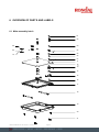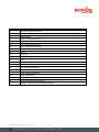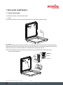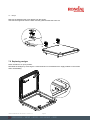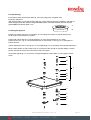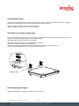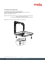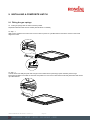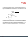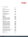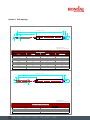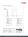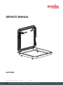
1
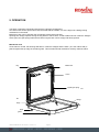
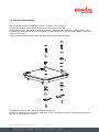
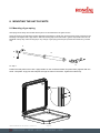
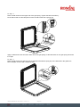
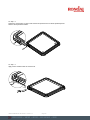
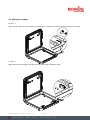
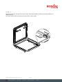
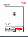
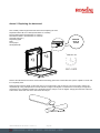
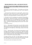
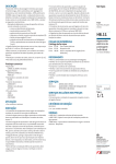
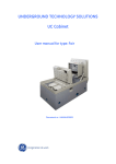
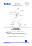
SERVICE MANUAL HATCHES SERVICE MANUAL HATCHES – Version 13 Page 1 Spars & rigging winches hatches deck equipment doors Table of contents 1. Introduction .......................................................................................................................................... 3 2. Safety issues and warnings ............................................................................................................... 3 3. What to check before fitting the hatch .............................................................................................. 4 4. Fitting hatches ..................................................................................................................................... 4 4.1 Fitting hatches with an aluminium or stainless steel gutter .............................................................4 4.2 Fitting hatches with a carbon gutter ................................................................................................4 5. Operation .............................................................................................................................................. 5 6. Overview of parts and labels ............................................................................................................. 6 6.1 Main-assembly hatch......................................................................................................................6 7. Replacing components ....................................................................................................................... 8 7.1 Hatch disassembly .........................................................................................................................8 7.2 Replacing wedges ..........................................................................................................................9 7.3 Replacing the gas spring ..............................................................................................................10 7.4 Replacing the mechanical seal .....................................................................................................10 7.5 Dog lock disassembly ...................................................................................................................11 8. Mounting the hatchparts .................................................................................................................. 12 8.1 Mounting of gas spring ..................................................................................................................12 8.2 Teak decking .................................................................................................................................14 8.3 Fitting the dog lock ........................................................................................................................14 8.4 Fitting the hinges ...........................................................................................................................15 8.5 Fitting cover plates on the hinges ..................................................................................................15 8.6 Dismantling the hinges ..................................................................................................................15 8.7 Fitting screw-in type drains ............................................................................................................16 9. Installing a composite hatch ........................................................................................................... 17 9.1 Fitting the gas springs ..................................................................................................................17 9.2 Fitting the wedges ........................................................................................................................19 10. Instruction for electrical hatches .................................................................................................. 21 11. Hatch finish ..................................................................................................................................... 22 12. Maintenance .................................................................................................................................... 23 13. After sales & Repairs....................................................................................................................... 23 14. Technical specs ............................................................................................................................... 24 Annex 1 Mechanical seal....................................................................................................................24 Annex 2 Replacing the hatch seal ......................................................................................................25 Annex 3 Spare parts ...........................................................................................................................27 Annex 4 Gas springs .........................................................................................................................28 Annex 5 Electric diagram actuators ...................................................................................................29 SERVICE MANUAL HATCHES – Version 13 Page 2 Spars & rigging winches hatches deck equipment doors 1. INTRODUCTION This service manual is intended to give you a general idea of mounting and maintenance instructions for a Rondal hinged hatch, including, for instance, how to replace parts. Before installation and use, please read this manual thoroughly to ensure that you are entirely up to date with regard to the installation, operation and special features of the hatch. Please ensure that the hatches are only installed and operated by qualified people who have read and taken note of the contents of this manual. 2. SAFETY ISSUES AND WARNINGS When setting up, operating or servicing the hatch, please follow closely the instructions and guidelines given in this manual. Failure to do so may cause serious injury or material damage and will void any warranty. If any part of this manual is not clear please contact Rondal for instructions before carrying out any work on the hatch. All work on the hatch must be carried out by qualified technical personnel. This service manual should be considered as a constituent part of the hatch and must be kept for consultation until final disassembly and removal. Please store it in a safe, dry and shaded place and make sure it is always available for consultation. In case of damage, a new copy must be ordered from Rondal BV quoting the project number. Rondal address and contact details: Rondal bv Flevoweg 1d 8325 PA Vollenhove P.O. Box 52 8325 ZH Vollenhove The Netherlands Phone +31 (0)527 243500 Internet: www.rondal.com E-mail: [email protected] SERVICE MANUAL HATCHES – Version 13 Page 3 Spars & rigging winches hatches deck equipment doors 3. WHAT TO CHECK BEFORE FITTING THE HATCH Any temporary spacers between the lid and the gutter must not be removed until the hatch has been installed. If gas springs are supplied with one or both ends loose in the gutter, do not fit these gas springs until the hatch has been installed. When the deck camber is not the same as the hatch camber, do not force the hatch as this will lead to leakage. Instead, apply washers as needed to achieve full support. When dog locks are provided with temporary spacers, these spacers should be removed before teak decking (see section 8.4). 4. FITTING HATCHES N.B. Please read through all the instructions before commencing any work! 4.1 Fitting hatches with an aluminium or stainless steel gutter Before fitting the hatch, check the instructions provided by your supplier for the application of the bonding material used between deck and hatch. Place the hatch into the deck with the lid closed and drill and tap fastener holes in the deck using the hatch as a template. Bond the hatch onto the deck, taking into account items listed under 3. Screw in aluminium countersunk screws starting with the corners; moment on screws to be between 9.8 and 11.8 Nm (7.23 and 8.68 lbs ft). After hardening, remove any temporary spacers placed between lid and gutter. Any gassprings that were (partly) loose in the gutter can now be mounted (see 8.1) 4.2 Fitting hatches with a carbon gutter Before fitting the hatch, check the instructions provided by your supplier for the application of the bonding material used between deck and hatch. Bond the hatch in deck taking into account items listed under 3. After hardening, remove any temporary spacers placed between lid and gutter. SERVICE MANUAL HATCHES – Version 13 Page 4 Spars & rigging winches hatches deck equipment doors 5. OPERATION The hatch is manually opened and closed using a dogging arrangement. On hatches that can be opened from both the inside and the outside, one of the dogs has a sliding locking mechanism on the inside. Before the hatch can be opened, this mechanism must first be unlocked. Opening then simply requires turning the dog below or above deck, so that it slides out from under the wedges. At this point, the gas springs will ensure that the hinged hatch can be simply and easily opened. Mechanical seal As the hatch is closed, the two dogs will slide–in under the wedges and the hatch ( incl. the rubber seal) is pushed against the top edge of the hatch gutter. This mechanical seal mechanism securely seals the hatch. dog rubber seal hatch regular gas spring blo blo wedge hinge drain gutter SERVICE MANUAL HATCHES – Version 13 Page 5 Spars & rigging winches hatches deck equipment doors 6. OVERVIEW OF PARTS AND LABELS 6.1 Main-assembly hatch 01 02 08 03 09 04 05 10 06 07 11 12 9 13 14 15 16 17 18 19 20 21 SERVICE MANUAL HATCHES – Version 13 Page 6 Spars & rigging winches hatches deck equipment doors Position Designation 01 Retaining ring Ø 32 x Ø 40 x 7 02 Axle + adjusting screw 03 Bearing bush 04 Holder + adjusting screw M5 x 6 05 Rubber seal ring Ø 58 x Ø 50 x 1 06 Nylon ring Ø 40 x Ø 24,2 x 1,5 07 Nut + adjusting screw M5x6 08 Hinge cover plate 09 Hinge 10 Hinge pin 11 Upper plate (glass / acrylic / aluminium) 12 Ring 13 Round nut Ø 60x40 + adjusting screw M5x6 14 Adjusting nut Ø 50x30 15 Dog (with inside handle) 16 Cylinder head hexagonal bolt M8x50 17 Hatch (including rubber seal) 18 Normal gas spring 19 Hatch gutter 20 Drain (including composite rings) 21 Wedge / countersunk crosshead screw M5x10 SERVICE MANUAL HATCHES – Version 13 Page 7 Spars & rigging winches hatches deck equipment doors 7. REPLACING COMPONENTS 7.1 Hatch disassembly To dismantle the hatch, follow the below steps: 7.1 - Step 1 Turn the dog and open the hatch so that the gas spring is extended to maximum length. 7.1 – Step 2 Remove the spring clip from the top and bottom of the gas spring. Detach the lower part of the gas spring by pulling the ball socket of the gas spring over the head of the ball plate. Then detach the upper part of the gas spring by turning it to the left of the ball joint. Take down both gas springs this way. N.B. As the gas springs are removed the hatch may fall shut, so please make sure that you hold it firmly in place at all times. ball socket spring clip ball plate gas spring SERVICE MANUAL HATCHES – Version 13 Page 8 Spars & rigging winches hatches deck equipment doors 7.1 – Step 3 Remove the stainless steel cover plates from the hinges. Unscrew the hinge bolts from the hatch and the gutter and take the hatch out. 7.2 Replacing wedges Place the hatch in an open position. Dismantle the wedges by removing the countersunk M5 x10 crosshead screw. Apply sealant on the screws when reassembling. SERVICE MANUAL HATCHES – Version 13 Page 9 Spars & rigging winches hatches deck equipment doors 7.3 Replacing the gas spring Remove the gas spring (as detailed in section 7.1, step 2) and fit the new one by following the procedure in reverse. 7.4 Replacing the mechanical seal 7.4 – Step 1 To replace the mechanical seal, first open the hatch. 7.4 – Step 2 Follow the instructions given in annex 2. SERVICE MANUAL HATCHES – Version 13 Page 10 Spars & rigging winches hatches deck equipment doors 7.5 Dog lock disassembly Remove the gas springs as explained in section 7.1 and then close the hatch. Unscrew the cylindrical M8 hexagonal bolts from the below-deck service bolt. Take out the nut bush. Remove the locking screw from the clamping bush and unscrew it from the axle. Take the below-deck locking screw out of the hexagonal nut and unscrew it from the axle as well. Remove the locking screw from the holder. Take the holder (including bearing bush, axle and seal) out of the hole above deck. To reassemble the bolt, follow the steps detailed in section 8.3. If there are multiple dog locks in a hatch, make sure you do not change the location of individual dog locks as each has its own direction of rotation. SERVICE MANUAL HATCHES – Version 13 Page 11 Spars & rigging winches hatches deck equipment doors 8. MOUNTING THE HATCH PARTS 8.1 Mounting of gas spring Gas springs must always be mounted with the piston rod end attached to the gutter section. Screw gas spring D into ball socket C after degreasing and applying Locktite 242. Screw the body end of gas spring D into ball hinge E and tighten with a pipe wrench. Remove securing clip A from ball socket C (piston end) and fit socket C onto ball B with a sharp tap; insert securing clip A. Any change of gas spring pressure (force) should be carried out by Rondal only. C B D A E 8.1 Step 1 Position the ball plate on the hatch. Apply sealant on the countersunk bolts and place them (together with the small –composite- rings) into the ball plate through the holes in the hatch. Tighten the bolts firmly. SERVICE MANUAL HATCHES – Version 13 Page 12 Spars & rigging winches hatches deck equipment doors 8.1 Step - 2 Place the ball socket on the upper end of the gas spring. Tighten the ball socket firmly. Fit the ball socket over the ball plate. Secure the ball socket with a spring clip. Apply Locktite 242 to the stud of the lower end of the gas spring. Fit the ball socket on the gas spring and screw it on tight. 8.1 Step - 3 Place the ball socket over the ball. Secure the ball socket with a spring clip. If the ball knob in the gutter has been changed, secure it with Locktite as well. SERVICE MANUAL HATCHES – Version 13 Page 13 Spars & rigging winches hatches deck equipment doors 8.2 Teak decking If the hatch surface requires teak decking, remove the dog locks A together with temporary spacers B. After applying teak, mount and bond the dog lock, with a sufficient amount of sealant in the teak lid. When margin boards are used around glass/PMMA panel, the space between the teak and the glass/PMMA should be at least 5 mm. A B 8.3 Fitting the dog lock If there are multiple dog locks in one hatch, do not change the location of individual dog locks, as each has its own direction of rotation. Position flat rubber seal 05 on spindle assembly A. Insert spindle assembly A in hatch. Position aluminium ring 12 onto spindle assembly A, than screw on locking nut 13 and tighten to 8 Nm/5.90 lbs ft. Tighten adjusting screw in locking nut 13. Screw adjusting nut 14 completely onto spindle assembly A. Mount inside handle 15 with socket screw 16, so that the hatch lid sits on the stop wedge in closed position and the top of the lid is flush with the top of the gutter. Screw down adjusting nut 14 so that it is positioned against inside handle 15, than tighten socket screw. 01 02 03 A 04 05 06 07 12 13 14 15 16 SERVICE MANUAL HATCHES – Version 13 Spars & rigging winches hatches deck equipment doors Page 14 8.4 Fitting the hinges Position the insulation plate over the drilled holes, than place the hinge on top of the insulation plate. Screw in the eight screws partway using anti-corrosive compound on the thread to prevent corrosion. Position the hatch in the gutter with even spacing all around. Tighten the screws (5.6 Nm/4.13 lbs ft). Mount cover plates. 8.5 Fitting cover plates on the hinges To allow proper fitting, the hinge may not be sunk more than two millimetres below the deck level. Before fitting the cover plates, clean and degrease the hinges and cover plates thoroughly. Use masking tape to protect the area around the hinge. Apply plenty of bonding material to the underside of the cover plate. Place the cover plate onto the hinge and press lightly. Remove any excess bonding material and make sure that the cover plates are aligned properly. Let the bonding material harden according to the supplier’s instructions. Insulation plates 4x 8.6 Dismantling the hinges Follow the instructions of section 8.4 and 8.5 in reverse order. SERVICE MANUAL HATCHES – Version 13 Page 15 Spars & rigging winches hatches deck equipment doors 8.7 Fitting screw-in type drains Once the hatch is installed, the drains can be fitted as follows. Slide one rubber ring B onto drain A and place the other rubber ring C in the hatch D. Screw drain A including the rubber ring B into the hatch D. Tighten the drain lightly with a wrench. Note 1: The drain is sufficiently tight as soon as the rubber ring B starts to deform; rubber ring C should also simultaneously be engaged. It is important that rubber ring B is not squeezed out from under the drain A. Note 2: Ring C is only used for aluminium hatches, not composite ones. D C B SERVICE MANUAL HATCHES – Version 13 Page 16 Spars & rigging winches hatches deck equipment doors 9. INSTALLING A COMPOSITE HATCH 9.1 Fitting the gas springs 9.1 Fit the gas springs after the hatch has been painted. Required materials include Innotec sealant (Rondal article no 342895) 9.1 Step - 1 Apply Innotec sealant to the sunk holes. Put the screws in place. Fit nylon M6 washers around the screws on the inside edge of the hatch. 9.1 Step - 2 Coat the back of the ball joint plate with enough Innotec sealant to fill up the empty space created by the flat rings. Fit the ball joint plate to the inside of the hatch and position it in front of the screws that have already been fitted with the flat nylon M6 washers. SERVICE MANUAL HATCHES – Version 13 Page 17 Spars & rigging winches hatches deck equipment doors 9.1 Step - 3 Tighten the screws firmly so that Innotec sealant is squeezed out from all the pressed spaces. Remove the superfluous sealant. 9.1 Step - 4 Apply Innotec sealant under the screw head. SERVICE MANUAL HATCHES – Version 13 Page 18 Spars & rigging winches hatches deck equipment doors 9.2 Fitting the wedges 9.2 Step – 1 Apply an ample amount of Innotec sealant to the inside of the nut flange, then place the button-headed nut in the gutter. 9.2 Step – 2 Apply sufficient Innotec sealant to the side of the stop block and fit it against the gutter. SERVICE MANUAL HATCHES – Version 13 Page 19 Spars & rigging winches hatches deck equipment doors 9.2 Step – 3 Place the stop block on the gutter at the exact location of the button-headed nut and fit the countersunk M5x16 mm hexagonal screw. Then firmly fasten the whole arrangement and remove the surplus sealant. SERVICE MANUAL HATCHES – Version 13 Page 20 Spars & rigging winches hatches deck equipment doors 10. INSTRUCTION FOR ELECTRICAL HATCHES N.B. Read through all the instructions carefully before commencing work. Always use the electric diagram to connect electrically operated hatches. Note that these hatches require 230 V AC power. See electric diagram: annex 5. Hatch operation requires the emergency dogs to always be in the open position. If the actuator is overloaded it will automatically shut down. It will subsequently reset itself and can immediately be used again. In case of failure of an electric actuator, disconnect one end of both actuators and shut the hatch, locking it with the emergency dog locks. Do not attempt repair of the actuator as it will lose its watertight integrity. Contact Rondal for a replacement. SERVICE MANUAL HATCHES – Version 13 Page 21 Spars & rigging winches hatches deck equipment doors 11. HATCH FINISH The standard hatch finish is as follows: Aluminium hatches feature polyester powder coating (a combination of epoxy and polyester resin). Stainless steel hatch gutters are polished using an electrolytic procedure. Carbon hatches are sanded smooth or painted in the required colour. 11.1 Technical advice for lacquering hatches pre-treated with polyester powder coating Undamaged and superficially damaged powder coated layers Clean the surface of any contamination using neutral soap solution, Coleman Fuel and, if necessary, siliconeremoving solutions. Sand the cleaned surface with an abrasive pad or 200 sandpaper. Dust and degrease the sanded area using Coleman Fuel. If necessary, apply a primer suitable to the finish. Paint the desired colour in one or two layers with an air-drying two-component polyurethane lacquer (PU) or an airdrying acrylic lacquer. You can do this using a brush, roller or airless spray-gun within the requirements stipulated by the paint manufacturer. Leave to dry and harden in the air for 3 to 15 days, depending on the temperature. Powder coated layers damaged so that bare metal is showing Clean the surface of any contamination using neutral soap solution, Coleman Fuel and, if necessary, siliconeremoving solutions. Sand the cleaned surface with an abrasive pad or 200 sandpaper. Dust and degrease the sanded area using Coleman Fuel. Treat the bare metal with anti-corrosive Alodine or an equivalent substance (conversion layer). Treat the entire surface or just the bare metal with anti-corrosive finish conditioner (containing zinc chromate), suitable to the finish. Sand and degrease again if necessary. Paint the desired colour in one or two layers with an air-drying two-component polyurethane lacquer (PU) or an airdrying acrylic lacquer. You can do this using a brush, roller or airless spray-gun within the requirements stipulated by the paint manufacturer. Leave to dry and harden in the air for 3 to 15 days, depending on the temperature. IMPORTANT: Never use an acrylic dispersion !!! 11.2 Application of paint on carbon fibre hatches: If the hatch is delivered already painted, it can be further treated and maintained in accordance with the onboard paint arrangement. If the hatch is delivered unpainted, it must be treated according to the current paint arrangements for carbon fibre surfaces. SERVICE MANUAL HATCHES – Version 13 Page 22 Spars & rigging winches hatches deck equipment doors 12. MAINTENANCE 12.1 General It is extremely important to properly maintain the hatches. All parts need to be checked for proper functioning on a regular basis. The hatches must be cleaned with fresh water and their drains checked for blockage on a regular basis. The gas springs, dog locks and hinge cover plates must also be cleaned regularly. Do not use abrasive cleaners. 12.2 Repair of scratches in PMMA (acrylic) material If there are numerous scratches in the PMMA components of the hatch, the hatch can be sent to Rondal for repair/polish or replacement of the PMMA panel, depending on your preference.. 12.3 Seal damage Regularly check the Ø 15 mm seal and the two dog lock seals for damage and degradation. A damaged seal must be replaced (see 8.3 annex 2 for instructions). 13. AFTER SALES & REPAIRS The Rondal service department is there to give you support should anything unfortunate happen with your Rondal hatch. We can also advise you on maintenance and repairs. One of our travelling engineers will visit you anywhere in the world to solve your technical problems and someone is always available at the Rondal factory for consultation. Additionally, several companies located in the major cruising areas have Rondal-trained engineers who can help you at a moment’s notice. Spare parts can be ordered through the service department, where a record is kept of all major items of Rondal equipment on each yacht. Those parts that can easily be shipped can, if you wish, undergo maintenance at Rondal’s facilities, where all the proper tools, testing facilities and – naturally – know-how are immediately available. SERVICE MANUAL HATCHES – Version 13 Page 23 Spars & rigging winches hatches deck equipment doors 14. TECHNICAL SPECS Annex 1 Mechanical seal R SERVICE MANUAL HATCHES – Version 13 Flevoweg 1d Phone: +31 527 243500 P.O. Box 52 Fax: 8325 ZH Vollenhove www.rondal.com Holland [email protected] Page 24 Spars & rigging winches hatches deck equipment doors +31 527 243900 Annex 2 Replacing the hatch seal N.B. Carefully read through all the instructions before replacing the seal. Required material: Ø 15 mm seal (Rondal article no. 343002) Pop Ployolefin primer (Rondal article no. 220271) Permabond C79220 (Rondal article no. 220270) Omnivisk 1050 glue (Rondal article no. 342940) Degreasing agent Knife Tissue paper Small paintbrush REMOVE GLUE & CLEAN OMNIVISK 1050 Remove the old seal from the hatch. Remove all the remaining glue from the seal hollow with a piece of plastic or wood until it is completely clean. Determine the necessary length for the seal, then cut out a piece that is 100 mm longer. Then cut the seal to exactly the required length, using a sharp knife to cut both ends at an angle of 45 degrees. To achieve the correct angle, it might be a good idea to use a template consisting of a small tube with one end pre-cut to 45 degrees. Simply place the tube at the end of the seal on either side and cut the seal at the same angle. 50 mm SERVICE MANUAL HATCHES – Version 13 Page 25 Spars & rigging winches hatches deck equipment doors Apply Permabond Pop Polyolefin primer to the angled surfaces on both ends of the seal. Remove excess primer and allow two minutes for drying. Apply Permabond Glue 792 glue to one end of the seal, covering the whole angled surface. Rub the two ends of the seal against each other shortly, then fit them against each other and hold in position for two minutes to allow to dry. 1. 2. Permabond Pop Polyolfin Primer WAIT 2 MIN. Permabond Glue 792 glue Thoroughly degrease the seal and the seal hollow in the hatch. Allow approximately five minutes for the degreasing agent to fully evaporate. Apply a three-millimetre layer of Omnivisk 1050 glue in the seal hollow, using a small paintbrush to distribute the glue evenly over the complete surface of the hollow. Now wait for around two minutes (and no longer than five minutes). Carefully fit the seal in the hollow, taking care to position the seal joint at the dog lock side of the hatch. Keep the hatch closed for four hours and then remove excess glue. SERVICE MANUAL HATCHES – Version 13 Page 26 Spars & rigging winches hatches deck equipment doors Annex 3 Spare parts Article no. Dog lock: Seal in top of dog lock Flat ring seal under dog lock flange 069130 069065 Hinge: Cover plate gutter, width 58 mm Cover plate hatch width 58 mm Acetal bushing ø6 x 5 mm 069630 069640 069680 Hinge, heavy duty: Cover plate gutter, width 60 mm Cover plate hatch, width 60 mm Acetal bushing ø6 x 5 mm 069611 069612 069680 Water drains: Spigot 16 mm Spigot 22 mm Spigot 25 mm Rubber ring spigot 6 mm ø12/ø18 Rubber ring spigot 16 mm ø20/ø26 Rubber ring spigot 22 mm ø27/ø32 Rubber ring spigot 22 mm ø20/ø26 Rubber ring spigot 25 mm ø27/ø32 406050 406060 406070 406057 406058 406068 406058 406068 Gas springs: S/S gas spring ø 8/ø19, stroke 60 S/S gas spring ø 8/ø19, stroke 80 S/S gas spring ø 8/ø19, stroke 100 S/S gas spring ø 8/ø19, stroke 120 S/S gas spring ø 8/ø19, stroke 150 S/S gas spring ø 8/ø19, stroke 200 S/S gas spring ø10/ø23, stroke 100 S/S gas spring ø10/ø23, stroke 150 S/S gas spring ø10/ø23, stroke 200 S/S gas spring ø10/ø23, stroke 300 069547 069549 069550 069552 069555 069560 069520 069530 069540 069542 S/S friction gas spring, stroke 80 S/S friction gas spring, stroke 100 S/S friction gas spring, stroke 150 S/S friction gas spring, stroke 200 069548 069551 069556 069561 Ball hinge for gas spring, with mounting plate Ball hinge for gas spring, screw in Locking device for locking gas spring Securing clip locking device ball hinge Spring clip ball hinge 406250 406210 069320 406290 406270 General: Silicone hatch seal ø15 mm 343002 SERVICE MANUAL HATCHES – Version 13 Page 27 Spars & rigging winches hatches deck equipment doors Annex 4 Gas springs 2 x stroke + 45 mm Stroke A M8 B M8 10 10 Material S/S 316 Maximum force 550 Newton GASSPRING A (mm) Ø8 Ø8 Ø8 Ø8 Ø8 Ø8 Ø10 Ø10 Ø10 Ø10 Cat.no. 069547 069549 069550 069552 069555 069560 069520 069530 069540 069542 B (mm) Ø19 Ø19 Ø19 Ø19 Ø19 Ø19 Ø23 Ø23 Ø23 Ø23 Stroke (mm) 60 80 100 120 150 200 100 150 200 300 2 x stroke + 45 mm M8 Ø8 Ø19 Stroke M8 10 10 Material S/S 316 Maximum force 200 Newton FRICTION GASSPRING Stroke (mm) 80 100 150 200 Cat.no. 069548 069551 069556 069561 SERVICE MANUAL HATCHES – Version 13 Page 28 Spars & rigging winches hatches deck equipment doors Annex 5 Electric diagram actuators SERVICE MANUAL HATCHES – Version 13 Page 29 Spars & rigging winches hatches deck equipment doors