1
INSTRUCTION MANUAL
Acoustic Wave Series
- Level, Flow, Positioning, Collision Protection -
A higher level of performance
Acoustic Wave Series
Manual
Rev 1.71, Mar 2011
CONTENTS
PROPRIETARY NOTICE
The information contained in this publication
is derived in part from proprietary and patent
data. This information has been prepared for
the express purpose of assisting operating and
maintenance personnel in the efficient use of
the instrument described herein. Publication of
this information does not convey any rights to
use or reproduce it, or to use for any purpose
other than in connection with the installation,
operation and maintenance of the equipment
described herein.
WARNING
This instrument contains electronic components
that are susceptible to damage by static
electricity. Proper handling procedures must
be observed during the removal, installation, or
handling of internal circuit boards or devices:
Handling Procedure:
1. Power to unit must be removed prior to
commencement of any work.
2. Personnel must be grounded, via wrist strap
or other safe, suitable means, before any
printed circuit board or other internal devices
are installed, removed or adjusted.
3. Printed circuit boards must be transported
in a conductive bag or other conductive
container. Boards must not be removed from
protective container until the immediate time
of installation. Removed boards must be
placed immediately in a protective container
for transport, storage, or return to factory.
Comments:
This instrument is not unique in its content
of ESD (electrostatic discharge) sensitive
components. Most modern electronic designs
contain components that utilize metal oxide
technology (NMOS, CMOS, etc.). Experience
has proven that even small amounts of static
electricity can damage or destroy these devices.
Damaged components, even though they appear
to function properly, exhibit early failure.
General Description, Features
2
Typical Applications
3
Application References
4
Dimensions
- Smart, Integral, Remote Units
- Suggested Mounting Dimensions
8
Mounting
- Typical Installations
- Installation Guide
- Open Channel Flow
12
13
16
Wiring
- Terminal Layouts
- Remote Transducers
- 4-20mA output
- Relay Functions
- Cross Talk Prevention
- Multidrop Connections
- 2 Wire Unit Communications
- HawkLink GSM
- Test Terminal
- Lightning Protection
18
21
22
25
26
28
29
30
32
33
Setup Procedure
- Level Measurement
- Average Level
- Differential Level
- Open Channel Flow
- Positioning Measurement
- Gain Adjustment
- Recover Adjustment
- Setting the System
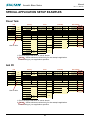
- Special Application Setup Examples
44
47
50
51
53
54
55
58
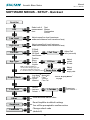
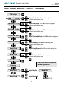
Software Menus
- Entering Data
- Software Tree
- Volume Adjustment
- Quickset
- Transducer Setup
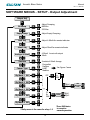
- Output Adjustment
- Comms
63
64
66
68
71
74
77
Advanced menus
- Tracking
- Differential Level
- Factory
Diagnostic Displays
Error codes
Sultan Safety Instructions
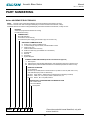
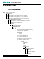
Part Numbering
Specifications
Sound Velocity Table
CE Declaration & Certificates
Contact Information
78
79
80
82
91
97
99
100
Back Cover
Acoustic Wave Series
Manual
Rev 1.71, Mar 2011
GENERAL DESCRIPTION
FEATURES
The Sultan series is a range of leading
edge level instruments using Hawk’s
Acoustic Wave technology. The range
includes simple and also full featured level
and position transmitters and switches.
Functions are included for basic level or
position measurement, vessel linearisation,
differential or average level using two
sensors, and open channel flow calculation.
Flexible design allows operation from
a range of power supply configurations
including two wire loop power systems.
Various digital communications protocols
are supported as options.
• The SULTAN 234 Series Acoustic
Wave Range offers a wide and
comprehensive range of advantages
• Large selection of transducers
• Self cleaning transducers
• No contact between the transducer and
the material
• Suitable for measuring rocks, powders,
viscous and aggressive media
• Power supply flexibility allows for 2 wire
loop power, AC and DC supplies all
within a single amplifier
Principle of Operation
• Easy to calibrate and commission
A SULTAN 234 Series sensor transmits a
high powered acoustic wave pulse, which
is then reflected from the surface of the
material or target to be measured.
• Wide spectrum of applications.
• Multiple head capability to reduce cost
per unit (max 128 points)
Reflected signals are processed using
highly developed algorithms to enhance the
correct signal and reject false or spurious
echoes.
• Open channel flow
• Differential Level
• Crane / positioning
The transmission of high powered, low
frequency waves ensures minimal losses
through the environment where the sensor
is working. The high initial energy of the
pulse, at penetrating low frequencies,
ensures that any signal losses which
do occur have far less negetive effect
than would be experienced by traditional
ultrasonic devices.
• Average of 2 inputs
• Transducer cross talk prevention
The sensitive receiver circuitry of the Sultan
series is designed to identify and monitor
low strength return signals even when
combined with high noise levels.
Measured signals are temperature
compensated to provide maximum accuracy
of the outputs and display.
Acoustic Wave Series
Manual
Rev 1.71, Mar 2011
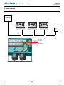
TYPICAL APPLICATIONS
SOLID PRODUCT LEVEL
LIQUID PRODUCT LEVEL
High / Low / Continous
Liquid / Chemical /Slurry
High / Low / Continous
Granular / Powder
Conveyed, pneumatic
air slide
Feeder
pipe
IP68
sensor
Flood
Hood
SULTAN 234
Remote
Amplifier
SULTAN 234
Optional
Remote GSM/CDMA
or
Panel Mount
Acoustic Wave Series
Manual
Rev 1.71, Mar 2011
Solution:
Hawk installed Sultan Acoustic Wave, 2 wire
loop powered 20kHz transmitter. The lower
frequency 20kHz transducer provided excellent
reliable control, during all sequences of the
sand filter process. Maximum range of the 2
wire 20kHz transmitter is 20 m (65 ft). When
the sand filter was drained the instrument
had no trouble monitoring the sand and the
backwash sequence, which the client could not
achieve with the conductivity probes.
Using the 20 kHz frequency transmitter,
provided a solution to cover all environment
changes, including rain, fog, snow, condensation, some frothing during back wash etc.
Hawk manufactures the largest range of
acoustic wave, 2 wire loop powered transmitters in the world, to suit all applications.
Note: Remote mounted transmitters, for the 2
wire loop powered range can be mounted up
to 700 m (2300 ft) from the transducer, using
belden 3084A cable.
Ordering information: (complete system)
Part no integral version:
AWI2SB20T4XXXX-FA4A-4-C04
Part no remote version: AWR2SBXXXXAWRT20T4XXXC6-FA4A-4-CO4-4
AP
NTEE
Application problem:
The customer had used conductivity probes
to control high and low level water in their
sand filter tanks. The probes were a problem
because the coated up with slime and required
routine cleaning.
ON GU
TI
RA
A
Reliable acoustic wave level technology
for water treatment plants, for monitoring
sand filter bed tanks
PLICA
APPLICATION REFERENCE
Acoustic Wave Series
Manual
Rev 1.71, Mar 2011
APPLICATION REFERENCE
Reliable level technology for coal
surge bins
Application problem:
The client had been looking for a reliable
level technology, to monitor level, in two 35
metre coal surge bins, that fill and empty
simultaneously.
Comments:
The client tried radar, from the three major
suppliers. The problem was that over a long
range (35 m), the beam angle of the radar
transmitters was too wide. The radar system
became unreliable beyond 20 metres. The
radar also suffered with build up in the focalizer cone, requiring cleaning on a periodic
basis.
Solution:
The new acoustic wave level transmitter was
installed and worked reliably over the full
range of the 35 m silo, during filling and emptying operations. The active pulse generated
by the acoustic wave transducer produced
self cleaning.
NTEE
AP
ON GU
TI
RA
A
PLICA
Ordering information:
Part number: AWRT10T4XXXC15XX +
FA10A-4 + C10-10-4 / AWR234SUXXXX
Acoustic Wave Series
Manual
Rev 1.71, Mar 2011
APPLICATION REFERENCE
Application Problem:
The client wanted to optimize the stockpile
height and automate the movement of the
tripper conveyer. The client also wanted block
chute detection for the coal feeder chutes.
The level transmitters also allowed the control
room to see the stockpile profile for inventory
control.
Solution:
The best technology solution for the level
transmitters was acoustic wave. The low frequency acoustic transmitter had a maximum
range of 100 metes and a very narrow beam
angle. Transducers were mounted on either
side of the tripper conveyer feeder chutes.
High speed response of the transmitters allowed for profile control. The blocked chute
control for the feeder chutes and transfer
chute of the conveyor used the Gladiator
microwave switches which have a pre-test
function and are non intrusive.
Both the Sultan acoustic transmitters and the
Gladiator microwave switches have totally failsafe capability.
For more application details contact the factory - contact details below.
Ordering information: (complete system)
2 x AWRT10S4XXXC15 + AWR234SUXXX +
Flange/Cone
3 x GSASUS + GMSB + GMRR
AP
NTEE
(This type of control can be applied to all types of tripper conveyer for
optimizing stockpile bunker levels and also providing protection for
blockages etc.)
ON GU
TI
RA
A
Aerial conveyor tripper control
PLICA
Coal Mine
Acoustic Wave Series
Manual
Rev 1.71, Mar 2011
APPLICATION REFERENCE
Reliable level technology for
liquid tanks in water treatment
plants
Application Problem:
Clients require reliable technology for measurement of liquid levels in a variety of tank
sizes and styles. Continuous, switch point
and communication options are all at times
required by different control systems. Typical
liquid tank applications are chemical storage
tanks, day tanks and dosing and mixing tanks.
Comments:
Smaller sized (1-5m), calm liquid tanks are
well suited to the compact high frequency
Sultan Integral (all in one) Acoustic Wave
product, using 2” BSP/NPT mounting. More
general applications with condensing vapour,
or foaming surfaces, agitation or over a little
longer range (1-10m), will only be reliable using slightly stronger, lower frequency (20kHz)
sensors, able to self clean with every high energy measuring pulse, mounted using Hawk’s
recommended flange and cone.
Solution:
Hawk provides Integral (all in one) and Remote (separate transmitter and transducer)
products from our Sultan Acoustic Wave
range, giving reliable, continuous and switch
point solutions for liquid tank level measurement, compatible with a variety of power supply and control output requirements.
AP
NTEE
Remote system- liquid tank:
AWR234SUXXXX
AWRT20T4XXXC6XX
FA4A-4 + C04-4
ON GU
TI
RA
A
PLICA
Ordering information:
Integral unit- small tank:
AWI234SU30T6TB20XXX
Acoustic Wave Series
Manual
Rev 1.71, Mar 2011
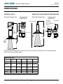
DIMENSIONS
SMART UNITS AND REMOTE TRANSDUCERS
305mm (12”)
C
2" BSP or NPT THD
See
Flange
Table
53.5mm (2.1")
See
Flange
Table
Integrated
Fixed cable
junction box
(only 2” BSP/NPT
versions)
1" BSP/NPT Nipple
D
75mm (2.9”)
80mm (3.1”)
3 x M16
Conduit
entries
110mm (4.3”)
Compact Type
(2”BSP/NPT)
B
82mm (3.2")
53.5mm (2.1")
B
A
A
All horns must protrude into the main volume of the vessel by at least 50 mm (2 inches) past the
lower end of the mounting nozzle.
Dimensions Table
Sensor
Frequency
Selected
Flange
A
mm in
mm
5 kHz
10”
236
455
10 kHz
10”
8”
236 9.2
195 7.6
15 kHz
10”
8”
236 9.2
195 7.6
20 kHz
4”
30 kHz
4”
B
C
D
mm in
in
mm
17.9
840 33.1
750 29.5
415 16.3
280 11.1
540 21.3
540 21.3
450 17.7
450 17.7
455 17.9
280 11.0
440 17.3
440 17.3
350 13.8
350 13.8
98.5 3.9
280
11.0
390 15.4
300 11.8
98.5 3.9
280
11.0
350
260 10.2
9.2
in
3.8
~80mm (3.1”)
160 mm (6.3”)
Standard Flanged Type
80mm (3.1”)
Compact Type
(2”BSP/NPT)
Standard Flanged Type
105mm (4.1”)
INTEGRAL UNITS
Acoustic Wave Series
Manual
Rev 1.71, Mar 2011
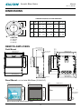
DIMENSIONS
STANDARD ANSI/DIN/JIS FLANGE DIMENSIONS
FLANGE
E (PCD)
TYPE
mm
in.
F(OD)
mm in.
G (ID)
mm in.
H (Hole)
mm in.
4”
FA4
FD4
FJ4
190.5
180
175
7.5
7.0
6.9
228
220
210
9.0
8.7
8.4
100
100
100
4
4
4
19
18
15
0.75
0.7
0.6
10”
FA10
FD10
FJ10
362
350
355
14.3
13.8
14.0
406
395
400
16.0
15.6
15.7
250
250
250
10
10
10
25
22
23
1.0
0.85
0.9
FA8
FD8
FJ8
298.5
295
290
11.8
11.6
11.4
343
340
330
13.5
13.4
13.0
200
200
200
8
8
8
22
22
19
0.85
0.85
0.75
SIZE
G
E F
8”
H
Note: Other flange sizes available upon request.
FLANGE TYPE:
FA = ANSI Flange
FJ = JIS Flange
FD = DIN Flange
REMOTE AMPLIFIERS
30.7 mm (1.2”)
7.5 mm (0.3”)
111.5 mm (4.4”)
Field Mount
78 mm (3.1”)
147 mm (5.8”)
158 mm (6.2”)
182.5 mm (7.2”)
50 mm (2”)
74 mm (2.9”)
192.5 mm (7.6”)
147 mm (5.8”)
131.5 mm (5.2”)
190 mm (7.5”)
107 mm (4.2”)
108 mm (4.3”)
190 mm (7.5”)
182.5 mm (7.2”)
167.5 mm (6.6”)
141.5 mm (5.6”)
14 mm (0.6”)
192.5 mm (7.6”)
174 mm (6.9”)
4 mm (0.2”)
Panel Mount - cut out size 90x90mm (3.54x3.54”)
Front
Back
Side
89.5mm (3.52”)
96mm (3.8”)
133.5mm (5.25”)
89.5mm (3.52”)
89.5mm (3.52”)
96mm (3.8”)
Allow clearance for securing clamp screws.
145mm (5.7”)
Allow clearance
for wiring here
Acoustic Wave Series
Manual
Rev 1.71, Mar 2011
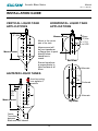
MOUNTING DIMENSIONS
20mm (0.79")
2 INCH BSP/NPT THREADED NOZZLE MOUNTING
2” Pipe Dimensions
(OD 60.3mm)
ID
(mm)
Thickness
(mm)
Schedule 5 - 5/ /5S
57.0
1.65
Schedule 10 - 10/ /10S
54.8
2.77
Schedule 30 - 30
54.0
3.18
Schedule 40 - 40/SYD/40S
52.5
3.91
Ensure the face of the sensor protrudes into the vessel
by more than 20mm
NOZZLE MOUNTING FOR SENSORS WITH FLANGE AND CONE
A
B
C
Roof of Tank
NOZZLE MOUNTING DIMENSIONS
A
B
C
100mm(4in) DIN, ANSI, JIS
240mm 9.44in
100mm
4in
150mm (6in) DIN, ANSI, JIS
240mm 9.44in
150mm
6in
200mm (8in) DIN, ANSI, JIS
300mm 11.80in
200mm
8in
250mm (10in) DIN, ANSI, JIS
390mm 15.35in
250mm
10in
10
Acoustic Wave Series
Manual
Rev 1.71, Mar 2011
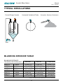
TYPICAL INSTALLATIONS
Conical Shape Vessels
Horizontal Cylindrical Tanks
Stockpiles, Stackers, Reclaimers
SULTAN 234
BLANKING DISTANCE TABLE
BLANKING DISTANCE
TRANSDUCER FREQUENCY
Minimum
Nominal
Conservative
AWRT50
50kHz
0.25m (10”)
0.3m (1ft)
0.35m (1.2ft)
AWRT40
40kHz
0.3m (1.1ft)
0.35m (1.2ft)
0.4m (1.4ft)
AWRT30
30kHz
0.35m (1.5ft)
0.4m (1ft)
0.5m (1.6ft)
AWRT20
20kHz
0.5m (1.6ft)
0.6m (2ft)
0.8m (2.6ft)
AWRT15
15kHz
0.6m (2ft)
0.7m (2.2ft)
1.0m (3.9ft)
AWRT10
10kHz
1.0m (3.3ft)
1.1m (3.5ft)
1.3m (4.2ft)
AWRT5
5kHz
1.2m (3.9ft)
1.4m (4.6ft)
1.5m (5ft)
Always use conservative nominated distances if possible
11
Acoustic Wave Series
Manual
Rev 1.71, Mar 2011
INSTALLATION GUIDE
AMPLIFIER - FIELD MOUNT
BLANKING DISTANCE
Where possible use the conservative values
and increase this distance by 50% if there
is foam, dust, steam, or condensation in the
vessel being monitored. (refer to table on
previous page.) If using a flange mounting,
use a rubber or neoprene gasket and
washers. If using a nipple mounting, ensure
that the mounting bracket is >6mm (0.24 in)
from the rear of the transducer. Do not over
tighten the lock nuts. When using a focaliser
cone, ensure that it protrudes at least 50mm
(2 in) into the vessel. If the transducer needs
to be mounted above the roofline, use an
appropriate standpipe or nozzle.
Use common sense when selecting the
mounting position. A clear line of sight from
the transducer to the product being monitored
is preferred.
Select a suitable mounting position that is
not in direct sunlight. If necessary, utilize
a sunshade. Observe the minimum and
maximum temperature limits (-20°C/-4°F
to 60°C/140°F) Do not mount near sources
of high E.M.F. such as high current cables,
motor starters, or S.C.R. variable speed
drives. Avoid mounting in high vibration areas
such as handrails and rotating plant. Use
rubber absorption mounts if mounting in light
vibration areas. Remove the P.C.B. assembly
before knocking out the cable and conduit
entry holes.
AMPLIFIER - PANEL MOUNT
- Select a suitable position within a panel
layout which allows clearance arround the
outside of the front panel of the unit.
- Ensure that sufficient space is available
behind the panel to accommodate the depth
of the amplifier housing, and also allow cabel
bend clearance for wiring to the terminals on
the rear of the amplifier.
- Mark and cut a 90x90mm (3.54x3.54”)
square cut out throught the panel in the
disired position.
- Insert the Sultan amplifier throught the panel
and install supplied screw clamps into the
slotted holes in the amplifier housing.
Tighten the screws until just firm to secure the
amplifier i place.
- Connect wiring as required to the corect
terminals on the removable rear panel
connectors. *When plugging connectors
in to the rear panel, ensure that they are
re-installed in the correct position (upper or
lower).
TRANSDUCER
Selecting a suitable position to mount the
transducer on the vessel is the single MOST
IMPORTANT step. Please read all of the
installation guide and contact your Hawk
representative if you have any doubts or
questions. The transducer face MUST be at
least the blanking distance away from highest
product level in the bin, tank, or silo at all
times. (refer to table below.)
MONITORING SOLIDS
In general, the transducer mounting position
can be determined by measuring the distance
from the infeed to the vessel wall, and
mounting the transducer l/3r this distance
from the wall. (refer diagrams pages 11, 13,
15.)
12
Acoustic Wave Series
Manual
Rev 1.71, Mar 2011
INSTALLATION GUIDE
Avoid mounting near ladders,
baffles, agitators etc.
(refer to Typical Applications)
MONITORING LIQUIDS
Mount the transducer perpendicular to
the liquid surface and away from the
infeed.
.06/5*/(104*5*0/
'-64).06/5 45"/%1*1&.06/5
/0;;-&.06/5
*OGFE
1JQF
7FTTFM
.JOJNVN
NN .JOJNVN
NN 53"/4%6$&3.06/5*/(
40-*% (SBOVMBS
-*26*%
%6"-065'&&%
108%&3
"JNUSBOTEVDFSBU
QPJOUPGPVUGFFE
5SBOTEVDFSTIPVMECFBT
QFSQFOEJDVMBSUPQSPEVDU
BTQSBDUJDBCMF
6TFUXPUSBOTEVDFSBOE
TFMFDUTFRVFODFPQUJPOUP
BWPJEDSPTTUBML
.PVOUBXBZ
GSPNJOGFFE
13
Acoustic Wave Series
Manual
Rev 1.71, Mar 2011
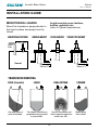
INSTALLATION GUIDE
TRANSDUCER MOUNTING
2" VERSION
Non preferred
Incorrect
Correct
Vessel
roof
min 20mm
inside tank
Hawk recommends a focaliser
cone for all transducers as they are
designed specifically to increase
the acoustic performance of the
Sultan product range.
Hawk supplies a variety of cones
for all Sultan Transducers.
Threaded mounting should only be
used where a flange/cone mounting
is impossible.
Intrusive
pipe
Intrusive
pipe
Bevel pipe end at 45 degrees
If a stand pipe MUST be used ensure a 45º angle is
cut to minimise echo return from the end of the pipe.
You may need to increase the Blanking parameter to
avoid seeing an incorrect return echo from the end
of the pipe.
14
Acoustic Wave Series
Manual
Rev 1.71, Mar 2011
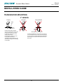
INSTALLATION GUIDE
VERTICAL LIQUID TANK
APPLICATIONS
HORIZONTAL LIQUID TANK
APPLICATIONS
50mm
(2") Min
R
Measurement
50mm
(2") Min
Measurement
Mount in the center
part of the tank
+/-1/4
to 1/3R
Measurement will
+/-1/4
to
1/3R
be from transducer
or flange face to point
directly below
transducer in
vessel.
Ensure transducer
is perpendicular to
liquid surface at all
times.
AGITATED LIQUID TANKS
End View
Alternate
+/-1/4
to
1/3R
Avoid mounting
over agitator if
possible
50mm
(2")
Min
R
Preferred
R
R
Alternate
Measurement
Top View
Center
Transducer
between
Blade and Tank Sidewall
15
Acoustic Wave Series
Manual
Rev 1.71, Mar 2011
OPEN CHANNEL FLOW MEASUREMENT PRINCIPLES
MOUNTING WEIR
5SBOTEVDFS
4VQQPSU
8FJS
5SBOTEVDFS
4VQQPSU
Êxää
£°Ç¸®
."9-FWFM
8FJS
Êxää
£°Ç¸®
."9-FWFM
16
Acoustic Wave Series
Manual
Rev 1.71, Mar 2011
OPEN CHANNEL FLOW MEASUREMENT PRINCIPLES
MOUNTING
PARSHALL FLUME
TVCNFSHFEnPX
GSFFnPX
RECTANGULAR
FLUME
0WFSBMMFEHF
YINBY
¡
ɋDN
6QTUSFBN
8BUFS
%PXOTUSFBN
8BUFS
17
Acoustic Wave Series
Manual
Rev 1.71, Mar 2011
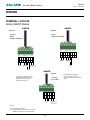
WIRING
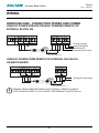
TERMINAL LAYOUTS
Sultan SMART Models
AWSTD
AWSTC
Outputs
Outputs
- 4-20mA
- Relay
- Modbus Multidrop
- Relay
- Modbus Multidrop
RELAY
RS - 485
YEL
GRN
YEL
(1) (1)
RELAY
RS - 485
24 Vdc
4-20mA
current sinking
24 Vdc
GRN
+
+
RD
BLK
A
BLU B
PPL Test in
WT
ORG NO
COMMS DC-in 4-20mA
+
+
BLK
RD
WT
BLU B
A
COMMS DC-in 4-20mA
PPL Test in
BWN COM
ORG NO
RELAY
BWN COM
RELAY
AWSTA
Outputs
For cable only models (without
integrated junction box option),
please use colors shown to
denote wire functions.
- 4-20mA
(2) Modbus
YEL
GRN
+
+
RD
A
BLK
Test in
BLU B
PPL
WT
COMMS DC-in 4-20mA
(1)
RS - 485
Notes:
(1) - No internal connection
(2) - Single Modbus connection PC to unit only
Multidrop connection not recommended
18
Loop Powered
4-20mA
current sinking
For models with integrated
junction box option, remove
plug-in terminal blocks for easier
wiring.
Acoustic Wave Series
Manual
Rev 1.71, Mar 2011
WIRING
TERMINAL LAYOUTS
Sultan 234 Models
AWI234 Series Transmitter
Integral Version (2 Relays)
– +
NO
AC-IN
N
L1
DC-IN
COM
RELAY 5
NO
NC
COM
NO
NC
COM
Test in
COMMS
B
A
NC
NO
COM
RELAY 4
WHITE
BLUE
+ –
4-20mA
DC-IN
BLACK
– +
RELAY 3
TRANSDUCER
RED
4-20mA
Is
Is
L1
N
– +
AC-IN
Test
4-20mA
NC
NO
COM
NC
NO
COM
RELAY 2
RELAY 1
RELAY 2
NC
Shld
A
B
COMMS
NO
COM
NC
RELAY 1
AWR234S Series Transmitter
Remote Field Mount (5 Relays)
90-260 VAC
90-260 VAC
Modulating 4-20mA
from PLC input
Modulating
4-20mA from
PLC input
Driving 4-20mA from Sultan to user PLC
Driving 4-20mA from Sultan to user PLC
NO
COM
RELAY 5
NC
COM
NO
RELAY 4
NO
NC
RELAY 3
NC
NO
NC
NO
COM
NC
COM
RELAY 2
RELAY 1
COM
AWR234P Series Transmitter
Remote Panel Mount (5 Relays)
AC-IN
DC-IN
L1
N
Top Row
+ –
COMMS
TRANSDUCER
4-20mA
– +
Is
RED
BLACK
BLUE
WHITE
Test in
A
B
Bottom Row
4-20mA
90-260 VAC
Modulating 4-20mA
from PLC input
Driving 4-20mA from Sultan to user PLC
19
Acoustic Wave Series
Manual
Rev 1.71, Mar 2011
WIRING
Sultan 2 Models
AWI2 Series Transmitter
Integral Version
SHLD
SHLD
B
A
4-20mA
WHITE
BLUE
RED
TEST
– +
BLACK
TRANSDUCER
4-20mA
4-20mA
COMMS
TEST
SHLD
B
A
COMMS
AWR2S Series Transmitter
Remote Field Mount
+ –
4-20mA
Modulating 4-20mA
from PLC input
Modulating 4-20mA
from PLC input
AWR2P Series Transmitter
Remote Panel Mount
COMMS
TRANSDUCER
4-20mA
– +
4-20mA
N/C
RED
BLACK
BLUE
Test in
WHITE
–
A
B
N/C
N/C
N/C
N/C
Bottom Row
Modulating 4-20mA
from PLC input
20
Acoustic Wave Series
Manual
Rev 1.71, Mar 2011
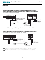
WIRING
REMOTE TRANSDUCER CONNECTION
Connection via Junction
Box and Extension Cable
Direct Connection to
Transducer Cable
BLACK WIRE
Cable
Shield
BLACK
BLUE
(for cable extension)
RED
at transmitter end
OPTIONAL
JUNCTION
BOX
WHITE
BLUE
Re-connect
Cable Shield
to Black
All cable shields
connect to
WHITE
SHIELD
Connect
Cable Shield
to Black
TRANSDUCER
RED
BLUE
WHITE
RED
BLACK
TRANSDUCER
Sultan Remote
Amplifier
Note: Terminal
order varies with
different model
types, see
terminal layouts
page 21, 22.
BLACK
Sultan Remote
Amplifier
Seperate
Black/Shield
TRANSDUCER
“USE ONLY”
BELDEN 3084A
DEKORON IED183AA002
to extend transducer cable
TRANSDUCER
*When extending transducer cable using DEKORON shielded twisted pair
cable types, ensure that one pair is used to extend Blue and White, and
another pair is used to extend Red and Black.
21
Acoustic Wave Series
Manual
Rev 1.71, Mar 2011
WIRING
4-20mA Output Connection
Terminal Connections for AC Powered Operation
234 models with AC power option and SIM card positioned for 3/4 wire mode
a) 5 Wire – Driving from Internal Isolated Supply (Is)
NOTE:
Isolated current
output can be made
common with external
DC Supply Positive or
Negative if required.
(e.g. RL – connected to GND)
{
AC Supply
L1
N
Use
shielded
cable
+
PLC
DCS
IND
RL Max 270Ω
4-20mA
–
–
+
Is
4-20mA
90 - 260Vac
Supply
SULTAN
Terminal
Connection
Sultan output is
sourcing current
and provides
voltage to drive a
passive load, PLC
input or indicator.
b) Modulating from User’s External DC Supply (RL to Negative)
User DC Supply
NOTE: RL Max = 750Ω
if user DC Supply 24V
{
AC Supply
+
–
+
PLC
DCS
IND
–
RL Max 400Ω
4-20mA
Use
shielded
cable
–
+
Is
4-20mA
90 - 260Vac Supply
L1
N
SULTAN
Terminal
Connection
Sultan output is
sinking/controlling
current. Voltage to
drive current loop
must be provided by
PLC, indicator or
external DC supply.
c) Modulating from User’s External DC Supply (RL to Positive)
User DC Supply
NOTE: RL Max = 750Ω
if user DC Supply 24V
{
AC Supply
+
–
+
PLC
DCS
IND
–
Use
shielded
cable
RL Max 400Ω
4-20mA
22
–
+
Is
4-20mA
90 - 260Vac Supply
L1
N
SULTAN
Terminal
Connection
Sultan output is
sinking/controlling
current. Voltage to
drive current loop
must be provided by
PLC, indicator or
external DC supply.
Acoustic Wave Series
Manual
Rev 1.71, Mar 2011
WIRING
4-20mA Output Connection
Terminal Connections for DC Powered Operation – AWST models
and all 234 models with SIM card positioned for 3/4 wire mode.
d) 4 Wire DC– Driving from Internal Isolated Supply (Is)
+
–
+DC
GND
+
NOTE:
Isolated current output can
be made common with
+DC or GND if required.
(e.g. RL – connected to GND)
PLC
DCS
IND
–
–
+
Is
RL Max 270Ω
4-20mA
4-20mA
User
DC Supply
DC Supply
SULTAN Terminal Connection
Use shielded cable
Sultan output is
sourcing current
and provides
voltage to drive
a passive load,
PLC input or
indicator.
e) 3 Wire DC – Modulating from Common User Supply (RL to Negative)
+
–
+DC
GND
+
NOTE:
RL Max = 750Ω
if user DC Supply 24V
PLC
DCS
IND
–
RL Max 400Ω
4-20mA
Use
shielded
cable
–
+
Is
4-20mA
User
DC Supply
DC Supply
SULTAN Terminal Connection
Sultan output is
sinking/controlling
current. Voltage to
drive current loop
must be provided by
PLC, indicator or
external DC supply.
f) 3 Wire DC – Modulating from Common User Supply (RL to Positive.)
+
–
+DC
GND
+
NOTE:
RL Max = 750Ω
if user DC Supply 24V
PLC
DCS
IND
–
RL Max 400Ω
4-20mA
Use
shielded cable
23
–
+
Is
4-20mA
User
DC Supply
DC Supply
SULTAN Terminal Connection
Sultan output is
sinking/controlling
current. Voltage to
drive current loop
must be provided by
PLC, indicator or
external DC supply.
Acoustic Wave Series
Manual
Rev 1.71, Mar 2011
WIRING
4-20mA Output Connection
Terminal Connections for DC 2 Wire 4-20mA Loop Powered Operation
AWSTA, Sultan 2 and 234 models with SIM Card positioned for 2 wire mode.
g) 2 Wire DC Loop Powered
SULTAN
Terminal
Connection
+
–
+
NOTE:
Internal SMART
card configured
for 2 wire.
PLC
DCS
IND
–
RL Max 400Ω
4-20mA
Use
shielded
cable
24
–
+
Is
4-20mA
User DC Supply
Sultan provides
4-20mA current
control of the
same 2 wires
which supply DC
power to operate
the unit.
Acoustic Wave Series
Manual
Rev 1.71, Mar 2011
WIRING
RELAY FUNCTIONS
Level Switch Contact Action
Notes:
1. Sultan 2 and AWSTA versions do not
support relay outputs.
Relay - for Smart AWSTC/D versions
(Set Relay Parameters in Output
Adjustment menu via GosHawk2 software)
2. Sultan 234 versions operating in 2 wire
loop powered mode do not support relay
outputs.
Relay 1, 2 - for Integral 234 versions
(Set Relay Parameters in Output Adjustment menu via local keypad or GosHawk2
software)
3. L1 and L2 distances are measured from
the transducer face or flange face.
Relay 1-5 - for Remote 234 versions
(Set Relay Parameters in Output Adjustment menu via local keypad or GosHawk2
software)
4. L1 must be equal to, or less than L2.
Relay Action
State 1
Energise
EN
DeEnergise
DEN
FailSafe
system operating
FS normally
OFF
FailSafe
power/system/
FS measurement failure
Relay Status
L1
Above L1 or between L1 and
L2 after passing
above L1.
NC COM NO
NC COM NO
NC COM NO
NC COM NO
NC COM NO
L2
LED Status
HIGH LEVEL or
State 2
Remote Amplifier
terminal function
labels
L1
FALLING LEVEL
Below L2 or between L1 and
L2 after passing
below L2.
NC COM NO
NC COM NO
NC COM NO
NC COM NO
NC COM NO
NC COM NO
NC COM NO
NC COM NO
NC COM NO
NC COM NO
L2
LOW LEVEL or
RISING LEVEL
POWER FAILURE
25
Acoustic Wave Series
Manual
Rev 1.71, Mar 2011
WIRING
Cross Talk Prevention
Cross Talk may cause one or more of a group of
sensors located near to one another to generate
randomly false measurements and outputs whilst
giving correct performance at other times.
The term Cross Talk is used to refer to interference between acoustic wave units of the same
frequency located near to one another.
Sultan units emit high powered acoustic waves
so only a small loss of signal will and occur
through the environment where a sensor is working. As a result, transducers located near to one
another, or in a common space are likely to
‘hear’ direct or reflected signals from one
another.
Cross Talk is more likely to cause problems
where the applications require units to be programmed to accept fast changes of level.
It is recommended that units working near to
one another be linked according to the following
steps to eliminate the possibility of Cross Talk.
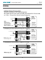
1. All units to be linked must be connected to a common ground, or have wiring between their ‘GND’,
or their ‘DC-’ terminals (parallel connection of all units).
* GND and DC- terminals are electrically connected inside Sultan 234 units, so either one may be
used.
SULTAN 2
26
N
AC IN
L1
+
DC IN
-
AC IN
N
+
-
N
DC IN
L1
+
-
SULTAN 2
AC IN
L1
SULTAN 1
DC IN
Acoustic Wave Series
Manual
Rev 1.71, Mar 2011
WIRING
Cross Talk Prevention
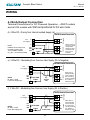
2. At each individual unit, wire a connection between Relay 1 ‘Common’ terminal and the ‘TEST’
terminal of the same amplifier.
3. Wire a connection between the Relay 1 ‘Normally Open’ terminals of all units to be linked
(parallel connection of all units).
SULTAN 2
B
A
COMMS
Test In
A
B
Test In
COMMS
NO
NC
RELAY1
NO
NC
A
B
Test In
COMMS
COM
RELAY1
NO
NC
COM
RELAY1
SULTAN 3
COM
SULTAN 1
4. In the software setup of each individual unit, program Relay 1 to ‘FS’ (Fail-safe) mode in the
Output Adjust menu. (You could use a different relay number in the same way if Relay 1 is needed
for another function). The units will now be linked so that they can not crosstalk.
The ‘TEST’ terminal acts as an input when the
unit is about to pulse, and will cause the instrument to enter a paused state (not pulse) if it sees
a connection to ground. Each unit also drives its
own ‘TEST’ terminal to ground when it is busy
pulsing. These two functions combined mean
that if two or more units have their ‘TEST’ terminals connected in parallel, and share a common
ground, then at any time when one is pulsing,
it will ground the ‘TEST’ terminals of all units to
which it is connected, and temporarily pause
them until it is finished, then release them. The
next unit which becomes ready to pulse will follow the same procedure in turn, and the process
continous in an endless cycle.
The connections described are made vis a
normally open rely contact, programmed into
Failsafe mode. The function of this is simply to
prevent a possible lock up of the whole system
if one unit has a problem e.g. power failure. If
at any stage a transducer is in its failed state, it
will be disconnected by the relay from the other
units, so they can continue to work together.
27
Acoustic Wave Series
Manual
Rev 1.71, Mar 2011
WIRING
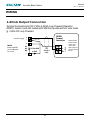
MULTIDROP CONNECTIONS
Multidrop GSM/GPRS/CDMA Connection*
A B Gnd
HawkLink
GSM/GPRS/CDMA unit
A B Gnd
A B Gnd
A B Gnd
Laptop or PC Communications using
PCMCIA card or wired (PSTN) modem
or Internet and remote GSM/GPRS/CDMA
connection with GosHawk software.
Multidrop Connection Using HawkLink USB*
A B Gnd
A B Gnd
A B Gnd
Hawklink
USB
A B Gnd
Laptop or PC Communications using
Hawklink USB or RS485 / 232 converter
with GosHawk software.
White
Blue
Black
Multidrop Connection to PLC/DCS/SCADA*
A B Gnd
A B Gnd
PLC / DCS / SCADA for Remote
Communication with Modbus.
A B Gnd
* Wiring installation should follow
RS-485 standards for layout and
termination.
28
Acoustic Wave Series
Manual
Rev 1.71, Mar 2011
2 WIRE UNIT COMMUNICATIONS
The Sultan 2 wire units are 2 wire loop powered
only. This means that they can not work when
multi-drop connected on Modbus networks. In
order to multi-drop connect units, they must not
be 4-20mA (2 wire loop) powered. Gladiator,
Orca, Sultan 234 or Smart AWSTC or AWSTD
types are necessary for networked installations.
When using an instrument powered by 2 wire
connection, all current must enter and leave an
instrument via the pair of loop wires, and fixed
connection of other terminals in parallel to other
units, or to a ground or common point may interfere with the operation of the unit, the current
output, or any communications.
The communications terminals on 2 wire units
are not designed for permanent connection and
networked use. Communication is possible with
these units, but only on a one to one basis, and
only without reference to any ground. Communications on these products are provided to allow
setup, commissioning and diagnosis, and during
actual communication, there may be some noise
generated on the current loop. It is normally best
to use a laptop running on battery power only,
connect only the A and B terminals, without the
ground/shield, in order to minimize any noise or
interference with the current loop.
29
Acoustic Wave Series
Manual
Rev 1.71, Mar 2011
WIRING
HAWKLINK GSM - CONNECTING POWER AND COMMS
USING DC POWER DERIVED FROM AC POWERED REMOTE OR
INTEGRAL SULTAN 234
2
3
80-265VAC
RS 485
4
1
AC-IN
2
N
80-265VAC
12-30VDC
3
L1
B
N
12-30VDC
L1
B
A
RS 485
1
SULTAN 234
COMMS DC-IN
AC-IN
A
GSM
COMMS DC-IN
Existing AC power
supply (GSM will be
powered by DC
generated by the Sultan)
4
Connect shield to
DC “-” only at this end.
USING DC POWER FROM REMOTE OR INTEGRAL SULTAN 234
OR AWSTC/AWSTD
2
12-30VDC
3
COMMS DC-IN
B
80-265VAC
A
N
A
B
RS 485
1
SULTAN/AW
AC-IN
L1
GSM
COMMS DC-IN
RS 485
4
1
2
12-30VDC
3
4
-
Existing DC power supply
Connect shield to
DC “-” only at this end.
!
TERMINAL ORDER VARIES BETWEEN SULTAN INTEGRAL, REMOTE, AN SMART
TYPES. ENSURE CORRECT LAYOUT IS USED - SEE TERMINAL LAYOUTS PAGE xxx.
30
Acoustic Wave Series
Manual
Rev 1.71, Mar 2011
WIRING
HAWKLINK GSM - CONNECTING POWER AND COMMS
USING SEPARATE AC OR DC POWER WITH REMOTE OR INTEGRAL
SULTAN 234 OR AWSTC/AWSTD
1
2
*
12-30VDC
RS 485
1
AC-IN
N
Separate AC power supply
for the GSM module
or
DC power
supply
DC-IN
A
80-265VAC
B
N
L1
B
A
12-30VDC
RS 485
COMMS
AC-IN
L1
SULTAN / AW
GSM
COMMS DC-IN
80-265VAC
Existing AC
or
DC power
supply
2
Connect shield to
DC “-” only at this end.
*
Ensure separate DC supplies have the same ground potential
USING SEPARATE AC OR ISOLATED DC POWER WITH SULTAN 2,
SULTAN 234 IN TWO WIRE MODE, OR AWSTA
SULTAN / AW
1
2
12-30VDC
Separate AC power supply
for the GSM module
or
Isolated DC power supply
RS 485
1
4-20mA
-
A
80-265VAC
B
N
A
B
RS 485
COMMS
AC-IN
L1
GSM
COMMS DC-IN
4-20mA
2
DC 4-20mA loop
power supply
Connect shield to loop
“-” only at this end.
!
TERMINAL ORDER VARIES BETWEEN SULTAN INTEGRAL, REMOTE, AN SMART
TYPES. ENSURE CORRECT LAYOUT IS USED - SEE TERMINAL LAYOUTS PAGE xxx.
31
Acoustic Wave Series
Manual
Rev 1.71, Mar 2011
WIRING
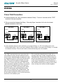
TEST TERMINAL - SULTAN 234 AND AWSTC/AWSTD ONLY
PAUSED MODE
The TEST terminal of an Sultan series
product can be used as an input to the
instrument, which cause it to pause in its
operation. During paused mode the unit
will stop making measurement pulses, and
the output will hold in its current position
(after any remaining damping to the current
position has finished). Internal echo tracking functions such as window opening and
hold time counting will continue to operate,
so that when the paused state is released,
the instrument will be immediately ready to
resume measurement allowing for possible
target movement during the paused time.
The test input can be used to silence a
Sultan system when it is not required to
measure, and is also used in the prevention
of Cross Talk, see page XXX.
To place a Sultan unit into paused mode
using the test input, a connection must be
made between the power supply ground or
DC- and the TEST terminal.
During paused mode, the word ‘Paused’
will be seen on the top line of the display if
viewing the operating mode diagnostic.
PAUSE FROM PLC/SCADA/DCS DIGITAL OUTPUT
Terminal Block
Test
PLC / SCADA / DCS Output
!
PLC/SCADA/DCS GROUND MUST
CONNECT BACK TO SULTAN
GROUND OR DC ‘-’ TERMINALS
OPERATOR CONTROLLED PAUSE
Terminal Block
Test
Externally provided
test switch
!
EXTERNAL SWITCH GROUND
MUST CONNECT BACK TO SULTAN
GROUND OR DC ‘-’ TERMINALS
32
Acoustic Wave Series
Manual
Rev 1.71, Mar 2011
WIRING
LIGHTNING PROTECTION
Connection
3 wires :- 1 to ground; 2 active (1 to each
loop connection). All need to be kept as
short as possible.
Surge Protection Device
Specifications
-
Description: Surge protector for
4/20mAprocess instruments.
-
Protection modes: Transverse &
common mode
-
Protection stages: Gas arrester/transorb
Remote Sultan
The enclosure can accommodate the
device mounted in one of the M20 cable
gland positions.
Surge rating: 20kA for 8/20µ s pulse
-
Transverse mode clamp: Voltage 36V
peak
-
Arrester firing voltage: 230V peak
-
Arrester residual voltage: 20V peak
-
Material: Nickel plated brass, epoxy
filled
-
Standards compliance:
IEEE C62.41 cat, A, B, C
AS1768-2003 cat. A, B, C
-
Integral Sultan
No M20 adaptor required
Approval:
AUS Ex2428U
Ex d IIC T4 Class 1 Zone 1
Ex ia IIC T4 Class 1 Zone 1
33
Acoustic Wave Series
Manual
Rev 1.71, Mar 2011
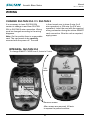
WIRING
CHANGE SULTAN 234 <=> SULTAN 2
is then turned over to show 2 wire (for 2
wire operation) or 234 wire (for 234 wire
operation). Insert the card with the required
wiring connection facing the sticker SMART
card connection. Wire the unit as required,
apply power.
It is necessary to have SULTAN 234
version to change to and from SULTAN
234 to SULTAN 2 wire connection. Wiring
must be changed according to the wiring
diagrams.
Note: On the module there is a removable
card. The card needs to be carefully
removed with the power off. The card
INTEGRAL SULTAN 234
To change SMART CARD from 3,4 wire to 2 wire.
Lift
cover
Remove screws
After screws are removed, lift facia
to expose the potted modules.
34
Acoustic Wave Series
Manual
Rev 1.71, Mar 2011
WIRING
CHANGE SULTAN 234 <=> SULTAN 2
Changing 2 wire to 3, 4 wire or 3,4 wire to 2 wire
Sim SMART CARD
Reverse/Remove
For correct sim SMART CARD
orientation, ensure the type of
connection faces the sim card
orientation sticker.
35
Acoustic Wave Series
Manual
Rev 1.71, Mar 2011
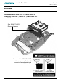
WIRING
CHANGE SULTAN 234 <=> SULTAN 2
Remote Sultan 234 > to change SMART CARD from 3, 4 wire to 2 wire
Sim SMART CARD
Reverse/Remove
Remove screws
and lift cover
For correct sim SMART CARD
orientation, ensure the type of
connection faces the sim card
orientation sticker.
For connection to GosHawk II, see
separate manual available on:
www.hawkmeasure.com
36
Acoustic Wave Series
Manual
Rev 1.71, Mar 2011
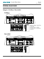
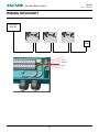
WIRING DIAGRAMS
Integral - Profibus / DeviceNet
Profibus
234 INTEGRAL TRANSMITTER
2 WIRE LOOP POWERED
TRANSMITTER WIRING AND
4 WIRE USER SUPPLY WIRING
USER
SUPPLY
DC
PLC
DCS
IND
RL MAX
500 7
4-20mA
DRIVING FROM INTERNAL
ISOLATED SUPPLY
PLC
DCS
IND
3 WIRE DC MODULATION
Is
RL MAX
400 7
4-20mA
USER
SUPPLY
DC
DC IN
PLC
DCS
IND
USER
SUPPLY
DC
PBDP out TEST
Aout Bout shld
AC-IN
N
DC-IN
-
+
STRIP INSULATION
9mm
LI
COMMS
RL1
A
B shld NC com NO
RL MAX
750 7
4-20mA
AWG 22 -14
(0.5 -1.5mm)
FOR LOOP POWER CHECK SMART CARD ORIENTATION
PBDP in
Ain Bin shld
DC-IN
- Minimum Voltage - 24vdc 0R ac
TO Our unit
- Nominal Current - 400mA
- Connector Type - Terminal see
wiring info
DeviceNet
234 INTEGRAL TRANSMITTER
2 WIRE LOOP POWERED
TRANSMITTER WIRING AND
4 WIRE USER SUPPLY WIRING
USER
SUPPLY
DC
RL MAX
500 7
4-20mA
PLC
DCS
IND
3 WIRE DC MODULATION
Is
RL MAX
400 7
4-20mA
USER
SUPPLY
DC
DC IN
PLC
DCS
IND
USER
SUPPLY
DC
FOR LOOP POWER CHECK SMART CARD ORIENTATION
DEVNET
A
B shld
LI
AC-IN
N
COMMS
RL1
A
B shld NC com NO
TEST
DEVNET
shld GND 24V+
DC-IN
-
+
37
STRIP INSULATION
9mm
PLC
DCS
IND
DRIVING FROM INTERNAL
ISOLATED SUPPLY
DC-IN
RL MAX
750 7
AWG 22 -14
(0.5 -1.5mm)
4-20mA
Acoustic Wave Series
Manual
Rev 1.71, Mar 2011
WIRING DEVICENET
DEVICENET
MASTER
SULTAN 234
SULTAN 234
SULTAN 234
EXT
TERM
5. V+
4. CAN_H
3. SHEILD
2. CAN_L
1. V-
38
Acoustic Wave Series
Manual
Rev 1.71, Mar 2011
DEVICENET
Set the BaudRate and the
DeviceNet Address in Sultan
5. DeviceID will be displayed
Factory defaults of baudrate and FBusAdds
are 125kbps and 63 in a Sultan unit with
DeviceNet CommType. To modify these
values follow the instructions below.
7. The default value for the BaudRate is
6. Use the Down push button to reach the
BaudRate parameter
125kpbs. Press CAL button and use the Up
and Down push buttons to modify this value
8. Press CAL button when finished
1. Go to the Output Adjustment menu
9. Use the Down push button to reach
2. Use the Up and Down push buttons to
the FBusAdds. The default value of the
reach the CommType parameter
FieldBus Address is 63. Press CAL button
3. Make sure that the CommTyle is set to
and use the Up and Down push buttons to
DeviceNet
modify this value
4. Press the CAL button twice
10. Press CAL button again when finished
Output Data
Profibus/Devicenet now transmit 18 bytes/9 words, description of the words is as follows (For firmware version 5.54 and above)
1. Displayed Distance (Space Distance is the Primary Variable)
2. Percentage (Percent of Range)
3. Hi Level (Upper Range)
4. Low Level (Lower Range)
5. Status Flags
Failed
Bit F ~~~~~~
Bit E Search
0
Echo Cfm : 1 = Echo R : 1 =
True, 0 = False True, 0 = False
Bit 3 Bit0 = Echo was received inside the span.
Bit1 = Echo is Confirmed.
Bit3 = Searching is searching for an Echo.
BitF = Unit has Failed to detect an Echo.
6. Displayed Distance2 (Second Variable)*
7. Percentage2 (Second Percent of Range)*
8. Displayed Distance3 (Third Variable)+
9. Percentage3 (Third Percent of Range)+
* Used for ORCA Sonar and Differential output on a Sultan
+Only used for ORCA Sonar Clarity output.
39
Bit 1 Bit 0
Acoustic Wave Series
Manual
Rev 1.71, Mar 2011
PROFIBUS
PROFIBUS
MASTER
SULTAN 234
SULTAN 234
SULTAN 234
EXT
TERM
5. B IN
4. A IN
3. SHEILD
2. B OUT
1. A OUT
40
Acoustic Wave Series
Manual
Rev 1.71, Mar 2011
PROFIBUS
Set the ProfiBus Address in Sultan
5. DeviceID will be displayed
Factory defaults of FBusAdds is 126 in a Sultan
unit with ProfiBus CommType. To modify this
value follow the instruction below:
dRate parameter.
6. Use the Down push button to reach the Bau7. The value for the BaudRate is selected automatically and can not be modified.
1. Go to the output Adjustment menu.
8. Use the Down push button to reach the
2. Use the Up and Down push buttons to reach
FBusAdds. The default value of the FieldBus
the CommType parameter.
Address is 126. Press CAL button and use the
3. Make sure that the CommType is set to
Up and Down push buttons to modify this value.
ProfiBus
9. Press CAL button again when finish.
4. Press the CAL button twice.
Output Data
Profibus/Devicenet now transmit 18 bytes/9 words, description of the words is as follows (For firmware version 5.54 and above)
1. Displayed Distance (Space Distance is the Primary Variable)
2. Percentage (Percent of Range)
3. Hi Level (Upper Range)
4. Low Level (Lower Range)
5. Status Flags
Failed
Bit F ~~~~~~
Bit E Search
0
Echo Cfm : 1 = Echo R : 1 =
True, 0 = False True, 0 = False
Bit 3 Bit0 = Echo was received inside the span.
Bit1 = Echo is Confirmed.
Bit3 = Searching is searching for an Echo.
BitF = Unit has Failed to detect an Echo.
6. Displayed Distance2 (Second Variable)*
7. Percentage2 (Second Percent of Range)*
8. Displayed Distance3 (Third Variable)+
9. Percentage3 (Third Percent of Range)+
* Used for ORCA Sonar and Differential output on a Sultan
+Only used for ORCA Sonar Clarity output.
41
Bit 1 Bit 0
Acoustic Wave Series
Manual
Rev 1.71, Mar 2011
COMMUNICATION - MULTIDROP CONNECTION
Gladiator
Admittance
Switch
Gladiator
Admittance
Switch
Gladiator
Admittance
Switch
Gladiator
Admittance
Switch
Sultan Acoustic
Wave Transmitter
Slurries
GLadiator
Microwave
Low Level
Gladiator
Microwave
Low Level
Sultan Acoustic
Wave Transmitter
Floatation Cells
Gladiator
Vibration
Switch
Sultan Acoustic Wave Transmitter
Silo, bin levels, coal, plastic powder,
woodchip, sawdust, cement,
clinker, iron ore, lime etc.
SULTAN 234
Gladiator
Conductivity
Switch
Sultan Smart Transducer
Farm Tanks, Grain Terminals
Orca Sonar Interface
Gladiator
Conductivity
Switch
SULTAN 234
Thickener, CCD
Sultan Acoustic
Wave Switch
Blocked Chute Detection
Orca Sonar Interface
Clarifier
Sultan Master/Slave Positioning System
GSM Network
or
CDMA Network
Sultan Acoustic Wave Transmitter
Stockpiles, Stackers,
Reclaimers
GSM or CDMA Network
• Typically up to 31 transmitters or switches per string.
• Maximum 250 transmitters or switches.
• Using GSM/CDMA network, transmitters and switches can be
monitored, calibrated remotely.
• Alarm status, diagnostics can be monitored.
• Support from factory engineering for customer application problems.
Laptop or PC Communications
or PLC / DCS with
MODBUS RTU Port
GosHawk Software for
inventory monitoring on PC
(Limited Modbus query rate for Switches only)
42
Acoustic Wave Series
Manual
Rev 1.71, Mar 2011
COMMUNICATION - REMOTE
GSM/CDMA Communication
HawkLink GSM/CDMA communication
device allows any authorized computer with
a standard modem and GosHawk software
to dial in and calibrate, test or check on the
performance of the connected Hawk product. The HawkLink device can be wired to
the standard communication terminals of the
Hawk products.
Protocols
GosHawk
HART
Modbus
Profibus DP
Profibus PA
Foundation Fieldbus
DeviceNet
Remote technical support and complete
commissioning of equipment in applications
via our GSM/CDMA module allows monitoring and adjustments of settings no matter
what corner of the world.
Remote connection worldwide!
43
Acoustic Wave Series
Manual
Rev 1.71, Mar 2011
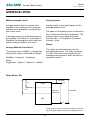
AVERAGE LEVEL
What is Average Level?
Analog Output
Average mode is used to measure the
average of two material levels using two
sensors and one amplifier, and provides
one output result.
Analog output is calculated based on the
average material level.
The span of the analog output is defined by
the LowLevel and HiLevel parameters. The
analog output is calculated as follows:
Current (mA) = 16* AvgMatrl/ (LowLevelHiLevel) + 4mA
In average mode, two individual sensors
are referred to as Sensor 1 and Sensor 2.
Capability for averaging of more than two
sensors may be added in the future.
Relays
Average Material Calculation
The relays are switched based on the
average space value. The relay set points
L1 and L2 should be set considering the
average space values at which the relay is
required to switch.
The display mode ‘AvgMatrl’ (Average Material) gives a result calculated as follows:
AvgMatrl = LowLevel – AvgSpace
where
AvgSpace = (Space1 + Space2 + offset)/2
Relay Mode = EN
L1
HiLevel
20 mA
OFF
L2
LowLevel
*Analogue
output span
ON
4 mA
* 4-20 mA action may be reversed according to setting of
the ‘Analog’ parameter in the Output Adjustment menu.
44
Acoustic Wave Series
Manual
Rev 1.71, Mar 2011
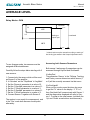
AVERAGE LEVEL
Relay Mode = DEN
L1
HiLevel
20 mA
ON
L2
LowLevel
*Analogue
output span
OFF
4 mA
* 4-20 mA action may be reversed according to setting of
the ‘Analog’ parameter in the Output Adjustment menu.
Accessing both Sensors Parameters
To use Average mode, two sensors must be
assigned different addresses.
Both sensor1 and sensor 2 parameters can be
accessed through KeyPad and GosHawkII.
Carefully follow the steps below starting with 2
new sensors:
Via KeyPad
The parameter ‘Sensor’ in the TxSetup, Tracking
and Factory menus determines which sensor (1
or 2) will be currently accessed via that menu.
1. Connect only the sensor which will be used
as Sensor 2 to the amplifier.
2. In ‘Quickset’ set the ‘DispMode’ to ‘AvgMatrl’.
3. Set the ‘Sensors’ parameter to a value of 2.
4. Set the ‘1:SenAdd’ parameter to a value of 1.
5. Set the ‘1:TxAdd’ parameter to a value of 1.
6. Set the ‘2:SenAdd’ parameter to a value of 1.
7. Set the ‘2:TxAdd’ parameter to a value of 2.
8. Connect Sensor 1 together with Sensor 2.
Via GosHawkII
When on Run mode, press the down key once
to get the ‘Tx’ value on the display. If ‘Tx’ is 1,
then GosHawkII will communicate with Sensor 1
and the diagnostics displayed will refer to Sensor 1. To swap to the other sensor, hold both the
‘Up’ and ‘Down’ arrow buttons simultaneously.
The system is now ready for measurement, and
in the ‘Run’ mode both sensors should pulse
alternately.
45
Acoustic Wave Series
Manual
Rev 1.71, Mar 2011
AVERAGE LEVEL
Junction Box
AWR2/AWR234
TX1
BOTTOM
AC-IN
L1
-
N
A
B
COMMS DC-IN
Test
WHT
BLU
4-20mA
TRANSDUCER
BLK
-
RED
ANALOG
Is
TX2
AMP
NO
COM
NC
NO
AWRT-JB-01
RELAY 5
TOP
COM
RELAY 4
NC
NO
COM
RELAY 3
NC
NO
COM
NC
RELAY 2
NO
COM
NC
RELAY 1
12-30VDC 90-265 VAC
46
Acoustic Wave Series
Manual
Rev 1.71, Mar 2011
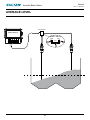
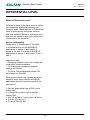
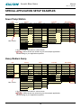
DIFFERENTIAL LEVEL
What is Differential Level?
Differential Level is the term used to define
the measured difference between two
material levels. Measurement of Differential
Level is achieved by using two sensors
and one amplifier. Below is reference as to
how the two sensors need to be setup and
connected to the amplifier.
Sensor Addressing
Parameters 1: SenAdd and 2: SenAdd:
in Quickset menu are the MODBUS
addresses of sensor 1 and sensor 2
saved in the unit. The default MODBUS
addresses of sensor 1 and sensor 2 are 1
and 2.
Important notes:
• Changing SenAdd, does not change the
transducer modbus address.
• To change the transducer address,
change the TxAdd.
• To get to TxAdd parameter press CAL
twice when on SenAdd.
Both sensors which are connected to the
amplifier must have different MODBUS
addresses then the following needs to be
carried out:
1. Set the application type to Diff on the
Sultan unit;
2. Connect the sensor that is used as
sensor No2.
3. Set 2:SenAdd to 1 and press Cal twice.
4. Set the 2:TxAdd to 2.
5. Connect Sensor No1.
47
Acoustic Wave Series
Manual
Rev 1.71, Mar 2011
DIFFERENTIAL LEVEL
Analog Output
Analog output is calculated based on the differential value.
The span of the analog output is according to the Lowlevel1 and Hilevel1. The
analog output is calculated according the following equation:
Current (mA) = 16 * (Diff)/(LowLevel1 –HiLevel1) + 4mA
Relays
The relays are switched based on the diff value. This means that the relay set points
L1 and L2 should be set to diff values that the relay is required to switch.
Relay Mode = EN (L1 < L2)
Relay Mode = DEN (L1 < L2)
OFF
L2 = Diff2
L2 = Diff2
L1 = Diff1
ON
L1 = Diff1
ON
OFF
Differential Mode
Differential Mode is introduced to measure the difference between two material
levels using two sensors and one amplifier.
Each sensor has its own Hi and Low levels. Parameters, LowLevel2 and HiLevel2
were introduced for sensor 2. This is useful when the sensors are not mounted at
the same levels.
Diff Calculation
In differential Mode the material level measured by sensor 1 is subtracted from the
material level measured by sensor 2. Negative results will be reset to zero. The
differential value is calculated as follow:
Diff = MaterialLevel2 – MaterialLevel1
MaterialLevel2 = LowLevel2 – Space2
MaterialLevel1 = Lowlevel1 –Space1
48
Acoustic Wave Series
Manual
Rev 1.71, Mar 2011
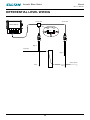
DIFFERENTIAL LEVEL WIRING
Junction Box
Junction Box
AWR2/AWR234
TX1
BOTTOM
N
-
AC-IN
L1
A
B
COMMS DC-IN
Test
WHT
BLK
4-20mA
BLU
-
RED
Is
TRANSDUCER
TX2
AMP
NO
COM
NC
NO
AWRT-JB-01
RELAY 5
TOP
COM
RELAY 4
NC
NO
COM
RELAY 3
NC
NO
COM
NC
RELAY 2
NO
COM
NC
RELAY 1
ANALOG
12-30VDC 90-265 VAC
High 2
up stream
High 1
down stream
Low 2
Low 1
49
Acoustic Wave Series
Manual
Rev 1.71, Mar 2011
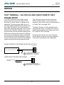
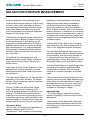
OPEN CHANNEL FLOW MEASUREMENT PRINCIPLES
OBSTRUCTIONS IN CHANNEL CAUSE RISE IN LEVEL
An obstruction in a channel represents
a reduction of the cross-section of the
channel. Since practical liquids are
essentially incompressible, the volume
of liquid flowing past an obstruction must
equal the volume flowing towards it. It
follows that the liquid must divert around
the obstruction.If a barrier to flow is
installed across the bottom of a channel,
the liquid level rises as it flows over it - this
leads to the use of the weir in open-channel
flow measurement. If the cross-sectional
area of a channel is reduced, the liquid
level must rise as it flows past - this leads
to the flume.
TVSGBDFPGMJRVJE
SJTFBCPWFXFJS
JODSFBTFTXJUI
nPXWPMVNF
nPX
XFJS
The height of the liquid surface above
the Weir is called the Flow Head (h). The
head is known to be related to the Volume
Flowrate (q), allowing the flowrate to be
calculated from measurement of the head.
Flumes, in which the channel width
is narrowed have become preferred
for accuracy and robustness (eg. self
scrubbing). Many flume profiles have been
developed, each having its advantages and
disadvantages for a given application.
A similar exponential relationship exists
between head and flowrate in these flumes,
and each type has a different exponent,
commonly in the range of 1.3 to 1.8.
The formula is of me form:
q = kha
where the exponent a is typically about
1.5 and the constant k depends upon the
channel and weir dimensions.
Different shapes of weir have been
developed to provide improved accuracy
under different conditions, but the principle
is the same for all. These various weirs
have different exponents, but most within
the range of 1.3 to 1.7.
50
Acoustic Wave Series
Manual
Rev 1.71, Mar 2011
SULTAN FOR POSITION MEASUREMENT
The Sultan series includes a product range
specifically designed for machine position
sensing. Such a system is typically used to
provide a signal representing the linear position
of a moving machine to a control system.
*Generally it is likely that placement of the
Master unit at a fixed location, and the Slave on
the moving machine will provide the simplest
and least costly installation, as control system
cabling then only needs to connect to a fixed
point, not via any moving cable system to the
moving machine.
Sultan’s high powered Acoustic Wave measurement technology applied in this way provides a
reliable, simple solution to measuring machine
positions in simple or difficult environments,
and is able to provide secure performance in
the presence of dust, steam and with complex
mechanical structures nearby.
-The customer may also choose to use Integral
or Remote systems for either the Master or
Slave parts.
*It is likely that the most convenient installation
style will include a Remote unit for the Master,
and an Integral for the Slave, as there is rarely
any need to access or adjust the Slave, and an
Integral unit is more compact and has a lower
purchase cost. At the Master end, however, a
Remote unit allows a convenient local display
of the measured position, and provides a neat
solution for connection of control wiring, and
easy adjustment of operating parameters at a
user accessible location, rather than directly at
the sensor position.
The system is a two part (Master-Slave) system, where each part is dimensionally similar
to a standard Sultan Integral or Remote level
measurement system.
The master system is in fact a standard Sultan
level system, with its software set for position
measurement. The slave system must be ordered specifically as it uses different components to the standard Sultan system.
-Each part: Master and Slave must be selected
to have the same operating frequency as one
another, as they work together to generate the
position measurement.
-The Slave unit requires only power supply connections, and the Master requires power supply
and control system signal connections.
Software Setup for Positioning Applications:
The basic setup of a system is done almost
entirely from the Master unit. There is rarely
any requirement to adjust the slave at all.
-One part is located at a fixed point, facing the
moving machine, in line with its axis of movement, and slightly beyond one end of its travel.
The second part is located on the moving
machine, facing the fixed unit in a direct line of
sight.
-All control system connections are made
ONLY to the Master unit. No control connections are required, nor available at the slave
end.
Adjustment of all parameters in the Master of a
positioning system is almost identical to what it
would be for a level application. The Sultan operation manual description of parameter setup
for level applies equally for positioning, with the
following simple differences:
-The customer may choose which part (Master
or Slave) is located on the moving machine, according to the location and availability of control
system inputs.
Quick Set:
-Low Level and High Level span points in the
instrument represent maximum and minimum
amounts of product in a level application. In
51
Acoustic Wave Series
Manual
Rev 1.71, Mar 2011
SULTAN FOR POSITION MEASUREMENT
a position application, these settings refer to
maximum and minimum positions of the moving
machine, so the High Level refers to the minimum separation between the sensor or flange
faces of the Master and Slave units, and the
Low Level represents the maximum separation
between the two sensor faces.
application should generally be significantly
lower than that which would be needed for
a level application over a similar distance.
Positioning signals are direct from Master to
Slave, or Slave to Master, and do not suffer the
losses in reflection, or absorption in a round trip
that would occur in a level application. If gain is
set higher than needed, then echo signals from
nearby structures can generate reflections and
give false outputs.
*Units should be mounted in such a way that at
least the minimum ‘Blanking Distance’ as given
on the specifications of the frequency of unit
being used is maintained between the Master
and Slave sensor faces at all times and all possible travel distances. It is recommended that
where possible, double the specified distance
should be used to provide some security margin in operation.
-Check that the ‘Gain Step’ is set to a slightly
lower value than the value selected above for
‘Gain’ (0.5% suggested minimum difference).
-Set the ‘Blanking Distance’ parameter to the
minimum separation distance possible between
the two sensors, with the moving machine at
its minimum extreme of physical travel. As
mentioned above, this must be greater than the
‘Blanking Distance’ given in the specifications.
-All distances for setup parameters, and
displayed distances in the ‘Space’ mode have
a zero reference at the face or flange of the
Master sensor.
-Set the ‘Empty Distance’ to slightly longer than
the maximum separation distance possible
between the two sensors, with the moving
machine at its maximum extreme of physical
travel.
-Select only ‘Position’ for the ‘Application Type’
parameter of the Sultan Software to provide
optimal performance when used for a positioning application.
-Normally, select ‘Space’ for the ‘Display Mode’
parameter of the Sultan Software. The display
will then show the separation distance between
the two sensor faces.
*Sensors used in positioning systems can normally be used over much longer distances (typically double) than the same sensors used in a
level application due to the lower losses with
direct transmission and reception of signals
compared to reflecting of a target.
-Set the ‘Fill Rate’ and ‘Empty Rate’ (found
under ‘Application Type’) according to the
maximum possible speeds of movement of the
machine: Fill Rate to the maximum speed (in
metres per hour) which the machine may move
toward the fixed sensor, and Empty Rate to the
maximum speed (in metres per hour) which the
machine may move away from the fixed sensor.
Advanced Note:
*The ‘Slope Distance’ used for positioning
systems is typically 2 times that used for level
applications.
*Gain Values for Gain Steps and Gain parameter are generally significantly lower than the
same frequency of instrument would use in a
level application.
Transducer Setup:
-Set the ‘Gain’ as required by the application to
achieve a reliable signal (0.8-2.5V).
*The setting of ‘Gain’ required for a positioning
52
Acoustic Wave Series
Manual
Rev 1.71, Mar 2011
GAIN ADJUSTMENT
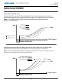
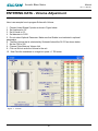
GAIN ADJUSTMENT (Gn)
Adjusting the Gn value will effect sensitivity of the acoustic wave system over the
entire span except for that controlled by Gain Steps. The Gain Slope is not affected.
Note: The higher the Gain Value the more sensitive the system becomes.
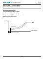
SLOPE ADJUSTMENT
Gain
High Gain
Medium Gain
Gmax
Low Gain
Higher Gn value
Lower Gn value
Time / Distance
Blanking and Gain Steps
Adjusting the Slope value will affect how fast the Gain rises over the entire span
except for that controlled by Gain Steps. The starting Gain is not affected.
Note: The lower the Slope Value, the steeper the Gain Curve is. The Slope value is
a distance in the selected units (metres or feet).
Low slope value
Gain
Medium slope value
Lower slope
High slope value
Higher slope
Gmax
Time / Distance
Blanking and Gain Steps
53
Acoustic Wave Series
Manual
Rev 1.71, Mar 2011
RECOVER ADJUSTMENT
RECOVER ADJUSTMENT
Gain changes automatically from Basic
Gain Curve to include additional Recover
Gain when neccessary.
Changes occur in small increments to a
maximum of the Recovery value.
Gain
Gmax
Recover value
Gn
Time / Distance
Blanking and Gain Steps
54
Acoustic Wave Series
Manual
Rev 1.71, Mar 2011
SETTING THE SYSTEM
Things to check
Check S value if less than approximately 1 volt increase Gn setting by
10%. The echo size should be at least 2.0 volts. Remember - anything
above the Threshold value closest to the sensor will be the displayed
E distance.
1
DISPLAY DISTANCE
CLOSER THAN ACTUAL LEVEL
unwanted echo is less than 0.5 volts. The
larger the size of the unwanted echo, the
less is the likelyhood of smooth transition
through this point when the level reaches
this distance.
If the distance displayed is incorrect and a
closer distance than the level echo heading
go to Map and map to a distance 10% (min)
past the unwanted echo.
The mapped echo must be smaller than
the actual level. A rule of thumb is the
level echo should be double the return
echo signal voltage size compared to the
mapped unwanted echo.
If the incorrect displayed distance has
a signal size greater than 1.0 volt it is
recommended to move the sensor until the
&DIP4J[F7PMUT
*ODPSSFDU&DIPN
$PSSFDU&DIPN
&
&
5ISFTIPME7BMVF
%JTUBODF N
N
N
E1 is the incorrect distance.
Ensure the signal size S: is less than 1.0 volts - if neccessary move the transducer
when E1 S value is less than 1.0V map to 2.2m.
To eliminate E1 from being considered as an echo when filling occurs at E2 is co-incident with E1 position. E2
55
Acoustic Wave Series
Manual
Rev 1.71, Mar 2011
SETTING THE SYSTEM
&DIP4J[F7PMUT
*ODPSSFDU&DIPN
$PSSFDU&DIPN
&
&
5ISFTIPME7BMVF
%JTUBODF N
N
N
E2 is more than double the size of E1, hence it is possible to monitor and follow E2
at this E1 mapped distance.
Note: It would be possible to increase the threshold value to a number greater than
the E1 signal S: value E1 then would be smaller than the threshold hence cannot be
seen by the software as a potential level echo.
56
Acoustic Wave Series
Manual
Rev 1.71, Mar 2011
SETTING THE SYSTEM
2
DISPLAY DISTANCE FURTHER THAN ACTUAL LEVEL
If the distance displayed is greater than the actual level, increase Gn until the
distance is displayed, on the diagnostic E: value then go to S: value and increase
Gn to read an approximate S: value of 2.0 volts.
E1 Actual Level
E2 Reflected larger echo
Echo Size Volts
E2
E1
Threshold Value
Distance(m)
By increasing Gn, it is possible to then monitor the correct level echo.
E1 Actual Level
E2 Reflected larger echo
Echo Size Volts
E2
E1
Threshold Value
Distance(m)
Note: It would be possible to lower the Threshold Value to ensure E1 is larger than
the Threshold Value
57
Acoustic Wave Series
Manual
Rev 1.71, Mar 2011
SPECIAL APPLICATION SETUP EXAMPLES
Diesel Tank
Info
Serial No:
Factory
Recover First(%):
0.0
Gain(%):
30.0
Low Level(m):
01
Slope Inc(%):
0.7
Recover Max(%):
0.0
Gain Step 3(%):
24.0
Hi Level(m):
0.429
0.403
Recover Inc.(%):
0.1
Dist Step 3(m):
0.900
Application:
Liquids
5.50
Detector:
12.620
01
GainStep1(%):
2.7
Window(m):
0.160
Threshold:
0.40
Rate of Fill:
0.3
22607
DistStep1(m):
0.350
Win Fwd(m):
0.001
Blanking(m):
0.400
Damp Fill:
100
0.001
EmptyDist(m):
30.000
Rate of Empty:
0.3
3407
Damp Empty:
100
Tx Model No:
Tx SoftVer:
Quick Start
0.300
ModbusID:
Tx Serial No:
Tx Setup
Slope Dist(m):
Type:
SoftVer:
Track
15944
20
GainStep2(%):
15.1
Win Back(m):
4.78
DistStep2(m):
0.500
Confirm:
01
GainMax(%):
96.0
Tx ModbusID:
Use 20 kHz
Dist Adj(m):
0.052
Velocity:
1.0000
Fail Safe Time:
3000
Noise Sw(%):
98.7
MapDist(m):
2.000
Lock Code:
0
3156
Echo Width(m):
0.030
MapUsed(m):
0.000
Disp Mode:
Material
208
Search First(%):
PulseRate:
Frequency:
Filter:
40
8.000
20
I-Waste:
Temp Adj:
Tx Voltage:
PulsePwr:
0.500
AdvFilter:
96
I-Charge:
110.0
Hold:
2
Movement(m):
No of Echo:
0.0
MapMargin(%):
Failsafe: 20.00mA
180
1.1
0.020
10
1. Do not change fields with no values shown
2. Circled - Values shown are suited only for the example application.
Set according to your application specifics.
Ash Pit
Info
Serial No:
Factory
Tx Setup
Quick Start
Slope Dist(m):
0.300
Recover First(%):
14.9
Gain(%):
34.9
Low Level(m):
00
Slope Inc(%):
0.7
Recover Max(%):
14.9
Gain Step 3(%):
20.0
Hi Level(m):
3.420
0.403
Recover Inc.(%):
0.1
Dist Step 3(m):
1.200
Application:
Liquids
10.0
Type:
SoftVer:
Track
13744
5.61
ModbusID:
Detector:
9.420
01
GainStep1(%):
2.7
Window(m):
1.000
Threshold:
0.40
Rate of Fill:
Tx Serial No:
18629
DistStep1(m):
0.350
Win Fwd(m):
0.100
Blanking(m):
1.200
Damp Fill:
Tx Model No:
20
GainStep2(%):
14.9
Win Back(m):
0.100
EmptyDist(m):
30.000
Rate of Empty:
10.0
4.78
DistStep2(m):
0.500
Confirm:
2
Temp Adj:
3386
Damp Empty:
8
01
GainMax(%):
96.0
Hold:
10
Dist Adj(m):
0.052
Tx SoftVer:
Tx ModbusID:
Use 20 kHz
15
Failsafe: 20.00mA
PulsePwr:
20
Tx Voltage:
8.000
Velocity:
1.0000
Fail Safe Time:
PulseRate:
3000
Noise Sw(%):
98.7
MapDist(m):
2.000
Lock Code:
0
Frequency:
3152
Echo Width(m):
0.030
MapUsed(m):
0.000
Disp Mode:
Material
222
Search First(%):
Filter:
I-Waste:
0.500
AdvFilter:
96
I-Charge:
110.0
Movement(m):
No of Echo:
0.0
MapMargin(%):
1.1
0.020
10
1. Do not change fields with no values shown
2. Circled - Values shown are suited only for the example application.
Set according to your application specifics.
58
180
Acoustic Wave Series
Manual
Rev 1.71, Mar 2011
SPECIAL APPLICATION SETUP EXAMPLES
Sewer Pump Station
Info
Serial No:
Factory
Tx Setup
Quick Start
Slope Dist(m):
0.300
Recover First(%):
4.0
Gain(%):
18.0
Low Level(m):
00
Slope Inc(%):
0.7
Recover Max(%):
4.0
Gain Step 3(%):
18.0
Hi Level(m):
0.500
0.403
Recover Inc.(%):
0.1
Dist Step 3(m):
0.900
Application:
Liquids
10.0
Type:
SoftVer:
Track
14284
3.93
ModbusID:
Detector:
7.000
01
GainStep1(%):
2.7
Window(m):
0.200
Threshold:
0.40
Rate of Fill:
Tx Serial No:
15127
DistStep1(m):
0.350
Win Fwd(m):
0.010
Blanking(m):
0.320
Damp Fill:
Tx Model No:
20
GainStep2(%):
15.1
Win Back(m):
0.010
EmptyDist(m):
30.000
Rate of Empty:
10.0
4.55
DistStep2(m):
0.500
Confirm:
2
Temp Adj:
3367
Damp Empty:
10
01
GainMax(%):
96.0
Hold:
10
Dist Adj(m):
0.052
Tx SoftVer:
Tx ModbusID:
Use 20 kHz
10
Failsafe: 20.00mA
PulsePwr:
20
Tx Voltage:
8.000
Velocity:
1.0000
Fail Safe Time:
PulseRate:
3000
Noise Sw(%):
98.7
MapDist(m):
2.000
Lock Code:
0
Frequency:
3135
Echo Width(m):
0.030
MapUsed(m):
0.000
Disp Mode:
Matrl%
213
Search First(%):
Filter:
I-Waste:
0.500
AdvFilter:
96
I-Charge:
110.0
Movement(m):
No of Echo:
0.0
MapMargin(%):
180
1.1
0.020
10
1. Do not change fields with no values shown
2. Circled - Values shown are suited only for the example application.
Set according to your application specifics.
Heavy Medium Sump
Info
Serial No:
Factory
0.450
Recover First(%):
0.0
01
Slope Inc(%):
0.7
Recover Max(%):
0.403
Recover Inc.(%):
5.50
ModbusID:
Tx Serial No:
Detector:
Quick Start
Gain(%):
20.0
Low Level(m):
30.0
Gain Step 3(%):
12.0
Hi Level(m):
0.500
1.5
Dist Step 3(m):
0.750
Application:
Slurry
01
GainStep1(%):
1.1
Window(m):
1.000
Threshold:
0.50
Rate of Fill:
22607
DistStep1(m):
0.500
Win Fwd(m):
0.100
Blanking(m):
0.500
Damp Fill:
Win Back(m):
0.150
EmptyDist(m):
30.000
Rate of Empty:
3407
Damp Empty:
Tx Model No:
Tx SoftVer:
Tx Setup
Slope Dist(m):
Type:
SoftVer:
Track
15944
15
GainStep2(%):
8.0
4.78
DistStep2(m):
0.700
01
GainMax(%):
96.0
Tx ModbusID:
Use 15 kHz
10
51.0
20
Dist Adj(m):
0.052
Velocity:
1.0000
Fail Safe Time:
3000
Noise Sw(%):
98.7
MapDist(m):
2.000
Lock Code:
0
3156
Echo Width(m):
0.100
MapUsed(m):
0.000
Disp Mode:
Space
208
Search First(%):
PulseRate:
Frequency:
Filter:
Temp Adj:
8.000
20
0.500
AdvFilter:
64
I-Charge:
110.0
Hold:
2
50.0
20
Tx Voltage:
PulsePwr:
I-Waste:
Confirm:
6.000
Movement(m):
No of Echo:
2.4
MapMargin(%):
1.1
0.020
10
1. Do not change fields with no values shown
2. Circled - Values shown are suited only for the example application.
Set according to your application specifics.
59
Failsafe: 20.00mA
180
Acoustic Wave Series
Manual
Rev 1.71, Mar 2011
SPECIAL APPLICATION SETUP EXAMPLES
Primary Jaw Crusher
Info
Serial No:
Factory
Tx Setup
Quick Start
Slope Dist(m):
0.300
Recover First(%):
0.0
Gain(%):
32.0
Low Level(m):
00
Slope Inc(%):
0.7
Recover Max(%):
0.0
Gain Step 3(%):
24.0
Hi Level(m):
2.000
0.403
Recover Inc.(%):
0.3
Dist Step 3(m):
0.900
Application:
Solids
100.0
Type:
SoftVer:
Track
11493
5.55
ModbusID:
Detector:
2.700
01
GainStep1(%):
2.7
Window(m):
2.000
Threshold:
0.40
Rate of Fill:
Tx Serial No:
12070
DistStep1(m):
0.350
Win Fwd(m):
1.000
Blanking(m):
1.600
Damp Fill:
Tx Model No:
20
GainStep2(%):
15.1
Win Back(m):
1.000
EmptyDist(m):
30.000
Rate of Empty:
100.0
4.78
DistStep2(m):
0.500
Confirm:
2
Temp Adj:
3360
Damp Empty:
4
01
GainMax(%):
96.0
Hold:
10
Dist Adj(m):
0.052
Tx SoftVer:
Tx ModbusID:
Use 20 kHz
4
Failsafe: 20.00mA
PulsePwr:
20
Tx Voltage:
8.000
Velocity:
1.0000
Fail Safe Time:
PulseRate:
3000
Noise Sw(%):
98.7
MapDist(m):
2.000
Lock Code:
0
Frequency:
3152
Echo Width(m):
0.030
MapUsed(m):
0.000
Disp Mode:
Space
197
Search First(%):
Filter:
I-Waste:
0.500
AdvFilter:
64
I-Charge:
110.0
Movement(m):
No of Echo:
2.4
MapMargin(%):
180
1.1
0.020
10
1. Do not change fields with no values shown
2. Circled - Values shown are suited only for the example application.
Set according to your application specifics.
Secondary Crusher
Info
Factory
Track
Tx Setup
Quick Start
Serial No:
10547
Slope Dist(m):
0.300
Recover First(%):
0.0
Gain(%):
36.0
Low Level(m):
Type:
32768
Slope Inc(%):
0.7
Recover Max(%):
0.0
Gain Step 3(%):
30.0
Hi Level(m):
1.100
0.403
Recover Inc.(%):
0.1
Dist Step 3(m):
1.500
Application:
Solids
100.0
SoftVer:
5.55
ModbusID:
Detector:
3.300
02
GainStep1(%):
2.7
Window(m):
2.000
Threshold:
0.40
Rate of Fill:
Tx Serial No:
21405
DistStep1(m):
0.350
Win Fwd(m):
1.000
Blanking(m):
1.500
Damp Fill:
Tx Model No:
20
GainStep2(%):
15.1
Win Back(m):
1.000
EmptyDist(m):
30.000
Rate of Empty:
100.0
4.78
DistStep2(m):
0.900
Confirm:
2
Temp Adj:
3390
Damp Empty:
4
01
GainMax(%):
96.0
Hold:
10
Dist Adj(m):
0.052
Tx SoftVer:
Tx ModbusID:
Use 20 kHz
4
Failsafe: 20.00mA
PulsePwr:
20
Tx Voltage:
8.000
Velocity:
1.0000
Fail Safe Time:
PulseRate:
3000
Noise Sw(%):
98.7
MapDist(m):
2.000
Lock Code:
0
Frequency:
3125
Echo Width(m):
0.030
MapUsed(m):
0.000
Disp Mode:
Space
211
Search First(%):
Filter:
I-Waste:
0.500
AdvFilter:
64
I-Charge:
110.0
Movement(m):
No of Echo:
0.0
MapMargin(%):
1.1
0.020
10
1. Do not change fields with no values shown
2. Circled - Values shown are suited only for the example application.
Set according to your application specifics.
60
180
Acoustic Wave Series
Manual
Rev 1.71, Mar 2011
SPECIAL APPLICATION SETUP EXAMPLES
Surge Bin
Info
Serial No:
Factory
Tx Setup
Quick Start
Slope Dist(m):
0.086
Recover First(%):
25.1
Gain(%):
14.9
Low Level(m):
00
Slope Inc(%):
0.1
Recover Max(%):
25.3
Gain Step 3(%):
16.0
Hi Level(m):
1.000
0.403
Recover Inc.(%):
0.3
Dist Step 3(m):
1.500
Application:
Solids
90.2
Type:
SoftVer:
Track
15379
5.50
ModbusID:
Detector:
02
GainStep1(%):
2.7
Window(m):
3.000
Threshold:
0.40
Rate of Fill:
Tx Serial No:
18252
DistStep1(m):
0.550
Win Fwd(m):
0.200
Blanking(m):
1.000
Damp Fill:
Tx Model No:
10
GainStep2(%):
8.0
Win Back(m):
0.150
EmptyDist(m):
18.000
Rate of Empty:
4.78
DistStep2(m):
0.850
Confirm:
2
Temp Adj:
3347
Damp Empty:
01
GainMax(%):
96.0
Hold:
8
Dist Adj(m):
0.108
Failsafe:
Tx SoftVer:
Tx ModbusID:
Use 10 kHz
14.800
6
63.5
6
4.00mA
PulsePwr:
100
Tx Voltage:
8.000
Velocity:
1.0000
Fail Safe Time:
PulseRate:
3000
Noise Sw(%):
98.7
MapDist(m):
14.800
Lock Code:
0
Frequency:
2854
Echo Width(m):
0.030
MapUsed(m):
14.800
Disp Mode:
Matrl%
183
Search First(%):
Filter:
I-Waste:
0.500
AdvFilter:
96
I-Charge:
110.0
Movement(m):
No of Echo:
0.0
MapMargin(%):
180
0.1
0.020
10
1. Do not change fields with no values shown
2. Circled - Values shown are suited only for the example application.
Set according to your application specifics.
ROM Bin
Info
Serial No:
Factory
Tx Setup
Quick Start
Slope Dist(m):
0.800
Recover First(%):
5.1
Gain(%):
20.0
Low Level(m):
00
Slope Inc(%):
0.7
Recover Max(%):
5.1
Gain Step 3(%):
16.0
Hi Level(m):
5.000
0.403
Recover Inc.(%):
0.1
Dist Step 3(m):
4.500
Application:
Solids
300.0
Type:
SoftVer:
Track
20970
5.56
ModbusID:
Detector:
14.000
01
GainStep1(%):
2.7
Window(m):
5.000
Threshold:
0.30
Rate of Fill:
Tx Serial No:
20769
DistStep1(m):
0.550
Win Fwd(m):
1.000
Blanking(m):
4.500
Damp Fill:
Tx Model No:
10
GainStep2(%):
8.0
Win Back(m):
0.100
EmptyDist(m):
25.000
Rate of Empty:
300.0
4.78
DistStep2(m):
1.500
Confirm:
2
Temp Adj:
3360
Damp Empty:
5
01
GainMax(%):
96.0
Hold:
20
Dist Adj(m):
0.108
Tx SoftVer:
Tx ModbusID:
Use 10 kHz
5
Failsafe: 20.00mA
PulsePwr:
100
Tx Voltage:
8.000
Velocity:
1.0000
Fail Safe Time:
PulseRate:
3000
Noise Sw(%):
98.7
MapDist(m):
10.000
Lock Code:
0
Frequency:
2900
Echo Width(m):
0.030
MapUsed(m):
10.000
Disp Mode:
Matrl%
181
Search First(%):
Filter:
I-Waste:
0.500
AdvFilter:
96
I-Charge:
110.0
Movement(m):
No of Echo:
0.0
MapMargin(%):
1.1
0.020
10
1. Do not change fields with no values shown
2. Circled - Values shown are suited only for the example application.
Set according to your application specifics.
61
180
Acoustic Wave Series
Manual
Rev 1.71, Mar 2011
SPECIAL APPLICATION SETUP EXAMPLES
Coal on Belt Detector
Info
Serial No:
Factory
Tx Setup
Quick Start
Slope Dist(m):
0.050
Recover First(%):
0.0
Gain(%):
30.0
Low Level(m):
00
Slope Inc(%):
0.7
Recover Max(%):
0.0
Gain Step 3(%):
26.0
Hi Level(m):
0.839
0.403
Recover Inc.(%):
0.4
Dist Step 3(m):
0.700
Application:
Solids
150.0
Type:
SoftVer:
Track
15325
3.98
ModbusID:
Detector:
1.154
57
GainStep1(%):
2.7
Window(m):
6.000
Threshold:
0.40
Rate of Fill:
Tx Serial No:
16097
DistStep1(m):
0.350
Win Fwd(m):
0.500
Blanking(m):
0.700
Damp Fill:
Tx Model No:
20
GainStep2(%):
15.1
Win Back(m):
0.500
EmptyDist(m):
10.000
Rate of Empty:
150.0
4.55
DistStep2(m):
0.500
Confirm:
1
Temp Adj:
3326
Damp Empty:
1
01
GainMax(%):
96.0
Hold:
40
Dist Adj(m):
0.052
Tx SoftVer:
Tx ModbusID:
Use 20 kHz
1
Failsafe: 20.00mA
PulsePwr:
20
Tx Voltage:
8.000
Velocity:
1.0000
Fail Safe Time:
PulseRate:
3000
Noise Sw(%):
98.7
MapDist(m):
2.000
Lock Code:
0
Frequency:
3220
Echo Width(m):
0.030
MapUsed(m):
0.000
Disp Mode:
Space
205
Search First(%):
Filter:
I-Waste:
0.500
AdvFilter:
64
I-Charge:
110.0
Movement(m):
No of Echo:
0.0
MapMargin(%):
180
1.1
0.020
10
1. Do not change fields with no values shown
2. Circled - Values shown are suited only for the example application.
Set according to your application specifics.
Cement Silo
Info
Factory
Track
Tx Setup
Quick Start
Serial No:
10747
Slope Dist(m):
0.400
Recover First(%):
22.0
Gain(%):
24.0
Low Level(m):
Type:
32768
Slope Inc(%):
0.7
Recover Max(%):
22.0
Gain Step 3(%):
24.0
Hi Level(m):
1.500
0.403
Recover Inc.(%):
0.1
Dist Step 3(m):
2.600
Application:
Solids
SoftVer:
ModbusID:
Tx Serial No:
Tx Model No:
Tx SoftVer:
Tx ModbusID:
Use 5 kHz
5.50
Detector:
15.500
01
GainStep1(%):
1.3
Window(m):
1.500
Threshold:
0.20
Rate of Fill:
0.6
6580
DistStep1(m):
1.350
Win Fwd(m):
0.002
Blanking(m):
1.500
Damp Fill:
600
0.004
EmptyDist(m):
05
GainStep2(%):
10.0
Win Back(m):
65.500
Rate of Empty:
3.3
4.73
DistStep2(m):
2.200
Confirm:
2
Temp Adj:
3360
Damp Empty:
24
01
GainMax(%):
96.0
Hold:
24
Dist Adj(m):
0.108
Failsafe: 20.00mA
PulsePwr:
150
Tx Voltage:
8.000
Velocity:
1.0000
Fail Safe Time:
PulseRate:
10000
Noise Sw(%):
98.7
MapDist(m):
2.000
Lock Code:
0
Frequency:
2821
Echo Width(m):
0.030
MapUsed(m):
0.000
Disp Mode:
Matrl%
25
Search First(%):
Filter:
I-Waste:
0.500
AdvFilter:
96
I-Charge:
110.0
Movement(m):
No of Echo:
0.0
MapMargin(%):
1.1
0.020
10
1. Do not change fields with no values shown
2. Circled - Values shown are suited only for the example application.
Set according to your application specifics.
62
180
Acoustic Wave Series
Manual
Rev 1.71, Mar 2011
SOFTWARE MENUS - ENTERING DATA
All software adjustments are achieved via the four
PUSHBUTTONS on the front panel of the Sultan amplifier.
FROM MAIN DISPLAY
(A) Press and hold - interups normal operations and allows
access to customised options.
Changes headings and allows EDIT function to occur.
IN SET-UP
(B) Momentary press – saves selected value.
Press and hold – scrolls through set-up menus and
parameters.
(A) Increases displayed value.
(B) Scrolls up through software set-up options.
(A) Decreases displayed value.
(B) Scrolls up through software set-up options.
(A) Only used when selections are finished.
(B) Stores the current set-up in memory, and checks the
validity of the software selections, then returns the Sultan
to normal operating condition.
Use these 4 buttons along with the ‘software tree’ to
customise the Sultan for your application.
63
Acoustic Wave Series
Manual
Rev 1.71, Mar 2011
SOFTWARE MENUS - ENTERING DATA
SOFTWARE
-«>Vi
N
$"-
6OMPDL
$"-
2VJDL4FU
0VUQVU"EK
$PEF
5Y4FU6Q
$PEF
5SBDLJOH
$PEF
1SFTT 36/ CVUUPOUXJDFUPSFWFSUUPOPSNBMPQFSBUJPO
64
Acoustic Wave Series
Manual
Rev 1.71, Mar 2011
SOFTWARE MENUS - ENTERING DATA - Diagnostic Display
(1) Go to Quickset and enter the values for the specific application.
When finished press RUN twice.
(2)
Go to diagnostic display, the display should show.
If you press the
Space
X.XXm
pushbuttons the following diagnostic are shown.
Space
4.221m
Damped distance
E:
4.2
Instant echo distance
S:
1.11V
Echo size in volts
Gn:
37.6%
Gain at distance echo is detected
R:
0.0%
The amount of gain to recover if the
echo is less than threshold detection
voltage level
N:
1.9%
Noise value
T:
23.2ºC
Temperature at sensor face
W
2.0m
Window starting distance
W
2.4m
Window finishing distance
Normal
Normal or recover. Normal if echo
is above threshold, Recover if below
threshold
65
Acoustic Wave Series
Manual
Rev 1.71, Mar 2011
ENTERING DATA - Volume Adjustment
Volume Menu
Volume User Guide
Volume Menu is used to calculate the volume
based on the material Level for different vessel
shapes. The calculated (Level, Volume) table
can be read from or written to a Sultan unit with
amplifier software version above or equal to
3.72.
1. Choose the Vessel Shape.
2. Set the LowLevel and HiLevel according to
your application.
3. Set the Vessel parameters such as L, w, d
and h1. Refer to the vessel figure for the definition of each parameter.
Volume Parameter Definitions
4. Set the values of h2 and h3 if required (optional). Tick the Enabled box to modify h2 and
h3. By default h3=HiLevel and h2=(LowLevel
- HiLevel).
5. Choose the Volume unit.
6. Enter Density or Full Scale values if necessary (optional).
LowLevel = Distance from the Face of the
transducer that corresponds to the low level in
the vessel (4mA Analog output).
HiLevel = Distance from the face of the transducer that corresponds to the high level in the
vessel (20mA analog output).
h3 = Distance from the face of the transducer to
the top of the vessel.
h2 = Total height of the vessel.
h1 = Height of the bottom section (cone or
pyramid base).
d = Diameter of the Cylinder Section.
d2 = Diameter of the Cone Base at the bottom.
w = Width of the rectangular section.
L = Breadth of the rectangular section.
MaxVolume = Maximum Calculated Volume of
the Vessel.
Density = Density of the material inside the
vessel.
Full Scale Value (FSV) = Maximum Capacity of
the Vessel.
Full Scale Value (FSV) = MaxVolume * Density
In the above equation, MaxVolume is calculated
by software and can not be modified. The user
may enter Density or FSV to determine the other
parameter.
7. Except the critical points that are shown with
red colour, any pair of (Level, Volume) points
can be modified. Double Click on the points to
modify.
8. Click on Write Volume to write the Level/
Volume table to the unit. This also saves the
application setting to the database.
To write successfully, unit must be on RUN
mode and amplifier software version must be
3.72 or above.
9. After writing to the unit, make sure that the
display of the unit changes to Volume and the
volume unit shown on the display is the same as
what you selected from GosHawk.
10. Click on Read Volume to read the volume
table from the unit if required.
66
Acoustic Wave Series
Manual
Rev 1.71, Mar 2011
ENTERING DATA - Volume Adjustment
Here is an example how to program Sultan with Volume:
1. Choose Vessel Shape Cylinder as show in Figure below:
2. Set LowLevel to 5.6
3. Set Hi Level to 0.5
4. Set diameter to 3.020
5. Do not select Optional Parameter. Make sure that Enable is not selected in optional
parameters
6. The Max Volume that is calculated by GoshawkII should be 36.531 as shown below.
7. Set the FSV to 200
8. Choose Cubic Meter as Volume Unit
9. Click on Write to write the Volume to the unit.
10. Now Face the transducer to a target at space = 1.709 meter
Figure 1: Volume
67
Acoustic Wave Series
Manual
Rev 1.71, Mar 2011
SOFTWARE MENUS - ENTERING DATA - Volume Adjustment
Now let’s calculate the Volume
Low Level – Space = 5.6 – 1.709 = 3.891, which is between point 23 (3.740) and point
24 (3.910), Vol at point 23 is 146.7, Vol at point 24 is 153.3, therefore, our Vol shown on
Tank View should between 146.7 and 153.3
- Volume shown on figure 2 is 152.6 which is between 146.7 and 153.3
- Check the Sultan unit display, Volume shown is 152.6cm
Mat
Vol %
Vol
Point 24
3.910
76.67
153.3
Point show on LED
3.891
76.29
152.6
Point 23
3.740
73.33
146.7
- Ok, let’s calculate this Volume by ourself:
Vol % = Mat / (LowLevel – HiLevel) * 100% = 3.891 / (5.6 – 0.5) * 100% = 76.29%
Vol = FSV * Vol% = 200 * 76.29% = 152.58 ->> 152.6
- Therefore, the Vol shown on Tank View form is the same as Vol shown on Sultan
display, and is the Volume level filled in the tank.
Figure 2: Volume shown in Tank View form
68
Acoustic Wave Series
Manual
Rev 1.71, Mar 2011
SOFTWARE MENUS - SETUP - Quickset
QUICKSET
To gain access to the parameter menu,
press and hold the
button until “Unlock
0” is displayed on the LCD. Then use the
buttons to select the access code.
The factory default is 0.
Fail-safe
Code
Application Type
Allows the user to select the type of application Liquids, Slurries, Solids. The
response of the system is automatically
changed to allow for application requirments.
Allows the user to select their preferred
Fail-safe condition. There are 5 possible mA output failure values. They are:
20mA, 4mA, Last Known, <4.00mA and
>20.00mA.
Allows the user to set an access code
other than 0 to avoid unauthorised
changes to the programming. Use the
buttons to select the desired access
code.
Fill Rate / Emp Rate
Allows the user to select the approximate
speed of the level change. This auto-matically sets various parameters to allow a
faster or slower response.
Units
Allows the user to select the units for
display of measured distances and relay
set point programming. The choices are
metres/centimetres or feet/inches.
Display
Allows the user to select the prefered display on the LCD, options Space, Material,
% Material, Flow, Avg Material, Dilhrd P,
Flow Tbl, volume
Low Level
Sets the distance from the face of the
transducer that corresponds to the low level
in the vessel being monitored -4mA analog
output level.
Flow
Allow open channel flow using q=kha.
High level
Sets the distance from the face of the
transducer that corresponds to the High
level in the vessel being monitored - 20mA
analog output level.
Note: When setting the High and Low
levels a minimum span of 100mm MUST be
maintained.
Flow Unit
Litres, k litres, m litres, Cube ft, Cube mtrs.
Flow Exp.
This is the Expontential of the flume.
Fail Time
Flow Max.
This is the maximum flow for the flume.
Allows the user to enter the number of
pulses when a last echo condition occurs
prior to failing. It is recommended to enter a
minimum of 50 pulses.
Lo Cut Off
This is the value, typically, when the flow is
less than 1cm in height it is deemed not to
be flowing.
69
Acoustic Wave Series
Manual
Rev 1.71, Mar 2011
SOFTWARE MENUS - SETUP - Quickset
QuickSet
CAL
Unit
CAL
Select unit of Feet
measurement Metres
from
Centimeters
Inches
Low Level
CAL
Adjust vessel low level (maximum
measured distance from transducer face)
High Level
CAL
Adjust vessel high Level (minimum
measured distance from transducer face)
Fail Safe
CAL
3.50mA
3.80mA
CAL
20.20mA
Last Known
App Type
CAL
Position
Slurry
Solids
Liquids
Fill Rate
CAL
CAL
*
*
Avg Matrl
Diff O/P
Space
Material
CAL
Adjust
vessel
fill rate
CAL
Adjust
vessel
empty rate
CAL
Note: If using GosHawk PC
comms, after changing ‘app type’
you need to reset fill & empty rate
to 1 and then enter your preferred values.
Display Mode
Adjust Fail
time (seconds)
Fail Time
Empty Rate
Material%
Flow
Volume
Flow Tbl
*
to ‘Display Modes’
* Go
on page
CAL
Sensor
Address
Default: 1
1: TxAdds
Transducer
IDs. Default 1
1: SenAdd
CAL
Offset
CAL
Enter distance offset value
AmpReset
CAL
Reset Amplifier to default settings
You will be prompted to confirm action
LockCode
CAL
Change unlock code
(default 0)
CAL
70
CAL
Acoustic Wave Series
Manual
Rev 1.71, Mar 2011
SOFTWARE MENUS - SETUP - TX Setup
Gain (Gn):
This is a settable level which repesents the
starting value for the units receiver gain
at the beginning of normal control (time
varying gain control). This value will take
over gain control after the last of the gain
limit steps (Gs/Ds). The true effect of this
parameter is to increase or decrease gain
levels (and echo sizes) at all points on the
gain curve, by moving the whole gain curve
up or down (as if holding it by its end). This
is generally used to increase or decrease
the size of echoes across the whole
measurement range (except for very close
to the transducer, which can be controlled
by fixed gain steps if required). Increasing
Gain (Gn) has a similar effect to decreasing
detection Threshold (Thld) and the reverse
is also true.
The result of changes can be seen
immediately as the unit pulses during
adjustment of this parameter and displays
the distance found (in SPACE mode without
damping). This parameter is duplicated
under the Tracking menu (only seen in
code 195). Changes made either here or
in Tracking will result in a change to both.
It is included twice in order to simplify user
access under code 0.
Gain Step (Gs):
Normally Gs and Ds must be considered
and adjusted as a pair, and should only
need adjustment to assist in masking
mounting or transducer related prolems.
The result of changes can be seen
immediately as the unit pulses during
adjust-ment of this parameter and displays
the distance found (in SPACE mode without
damping). This parameter is duplicated
under the Tracking menu (only seen in
code 195). Changes made either here or
in Tracking will result in a change to both.
It is included twice in order to simplify user
access under code 0.
Distance Step (Ds):
This value represents the distance from the
transducer face (in metres or feet as per the
user selection) over which a gain limit of Gs
will be applied. This gain limit can be used
to lessen the effect of poor mountings and
is the only one of the three gain steps which
should be used for field problem correction
(G1/D1 and G2/D2 steps are normally only
used at default values to hide transmit pulse
/ ringing).
Normally Gs and Ds must be considered
and adjusted as a pair, and should only
need adjustment to assist in masking
mounting or transducer related problems.
This value repsesents the maximum
receiver gain (%) at which the unit will
operate within a distance of Ds (described
below) from the transducer face. Inside
this distance the receiver may operate
at a lower gain if G1 and/or G2 are set to
lower values than Gs, otherwise the unit
will operate with a fixed gain value Gs for
measurement of distances up to Ds.
71
Acoustic Wave Series
Manual
Rev 1.71, Mar 2011
SOFTWARE MENUS - SETUP - TX Setup
The result of changes can be seen
immediately as the unit pulses during
adjustment of Ds either here or in Tracking
will this parameter and displays the
distance found (in SPACE mode without
damping).This parameter is duplicated
under the Tracking menu (only seen in
code 195). Changes made result in a
change to both. It is included twice in order
to simplify user access under code 0.
user access under code 0.
e.g: Solids and Powders = 0.5v to 1.75v
Thld:
The Velocity parameter can be used
to compensate measurements being
taken in gas mixtures other than air. The
speed of sound is changed by different
gas compositions, so an ultrasonic
measurement will be inaccurate by some
factor. Variation of this velocity factor until
the displayed distance is corrected to a
known measured distance will eliminate
errors due to the speed of sound differing
slightly to that found in air. Note that this
kind of compensation can only be effective
in a constant atmosphere.
Liquids = 0.5v to 2.0v.
DistTrim: (Y/N):
Select Y to access distance calibration
parameters.
Velocity:
The Thld (Threshold) parameter is a
settable size (in Volts), which an echo
must reach in order to be detected.
The instrument will accept the first
echo exceeding the threshold voltage
as the correct measured distance. It is
the user’s responsibility to ensure that
correct transducer positioning will always
make the first echo detected the true
level being measured (it will be if the
transducer has a clear “view” of the level
and no obstructions). Adjustment of the
gain control parameters and threshold
parameter can help to select a correct
echo from a number of different echoes
present. Increasing a threshold value will
also increase noise immunity if the echo
from the level is sufficiently strong. Do not
exceed a setting of 3.00 for Threshold.
The composition of gases being measured
through must be relatively constant with
time to maintain accuracy. Continuously
changing gas compositions in an atmosphere will reduce accuracy of ultrasonic
measurement.
Default value is 1.0000 for a compens-ation
factor of 1.0000 (no change from air).
The result of changes can be seen
immediately as the unit pulses during
adjustment of this parameter and displays
the distance found (in SPACE mode
without damping). This parameter is
duplicated under the Tracking menu (only
seen in code 195). Changes made either
here or in Tracking will result in a change to
both. It is included twice in order to simplify
72
Acoustic Wave Series
Manual
Rev 1.71, Mar 2011
SOFTWARE MENUS - SETUP - TX Setup
594FU6Q
$"-
(BJO
$"-
"EKVTU(BJO(O1SFTT$"-UPJOJUJBUFTJOHMFQVMTF
%JTUBODFUPFDIPXJMMCFTIPXO
36/
(BJO4UFQ
$"-
"EKVTU(BJO4UFQ(O1SFTT$"-UPJOJUJBUFTJOHMFQVMTF
%JTUBODFUPFDIPXJMMCFTIPXO
36/
%JTU4UFQN
5ISFTIPME7
$"-
"EKVTU%JTUBODF4UFQ1SFTT$"-UPJOJUJBUFTJOHMFQVMTF
%JTUBODFUPFDIPXJMMCFTIPXO
36/
$"-
"EKVTU5ISFTIPME7PMUBHF1SFTT$"-UPJOJUJBUFTJOHMFQVMTF
%JTUBODFUPFDIPXJMMCFTIPXO
36/
>}ÊÊÊÊÊä°Óx
"EKVTU#MBOLJOH1SFTT$"-UPJOJUJBUFTJOHMFQVMTF
%JTUBODFUPFDIPXJMMCFTIPXO
36/
&NQU%JTU
5FNQ5SJN
%JTU5SJN
$"-
$"-
"EKVTU&NQUZ%JTBODF1SFTT$"-UPJOJUJBUFTJOHMFQVMTF
%JTUBODFUPFDIPXJMMCFTIPXO
36/
"EKVTU5FNQ1SFTT#!, UPJOJUJBUFTJOHMFQVMTF
%JTUBODFUPFDIPXJMMCFTIPXO
36/
$"1SFTT36/UXJDFUPSFWFSUUP
OPSNBMPQFSBUJPO
7FMPDJUZ
.BQ%JTU
$"-
"EKVTU.BQ%JTU
.BQ&DIP
$"-
.BQ6TFE
$"-
"EKVTU.BQ6TFE
.BQ&DIP :&4/0
73
Acoustic Wave Series
Manual
Rev 1.71, Mar 2011
SOFTWARE MENUS - SETUP - Output Adjustment
4mA Adj:
Simulate:
Whilst the display shows ‘4mA Adj’, the
analog (4-20mA) current output will be
forced to its 4mA state. The actual loop
current can be measured with an external
meter and calibrated exactly by pressing
the UP or DOWN arrows until the external
meter reads exactly 4.000mA. Pressing the
CAL button will store the calibration in the
instruments memory.
(Y/N): Select Y to access measurement
simulation mode. In simulation mode, the
UP and DOWN arrow keys vary the distance on the display. The current output
and any relays used will behave exactly as
they should do if the measured distance (in
SPACE mode without damping) was that
shown on the display. This mode can be
used to test correct behavior of outputs, or
externally connected equipment.
Re-Calibration should only be necessary
if a complete model reset is performed
(in extended Tracking under code 195),
or if parts of the electronics assembly
are changed in maintenance or repair
operations.
RELAYS
Allows the user to set the relays for
switching. The relays are programmed in
a distance from the transducer face to the
position where switching is required. Relays
work in the following manner:
20mA Adj:
Whilst the display shows ‘20mA Adj’, the
analog (4-20mA) current output will be
forced to its 20mA state. The actual loop
current can be measured with an external
meter and calibrated exactly by pressing
the UP or DOWN arrows until the external
meter reads exactly 20.000mA. Pressing
the CAL button will store the calibration in
the instrument is memory. Re-Calibration
should only be necessary if a complete
model reset is performed (in extended
Tracking under code 195), or if parts of the
electronics assembly are changed in maintenance or repair operations.
OFF The relays will remain de-energised
regardless of the measured distance
or vessel contents.
The relays can be programmed to energise
or de-energise depending on the product
level in the vessel being monitored.
FS
Analog:
4-20/20-4mA The analog current output
of the instrument can be set to act in the
normal (4-20mA) or reverse (20-4mA)
directions. The default condition is 420mA, where the furthest distance from
the transducer (low level) is output as 4mA,
and current increases with filling to the
closer (high level) span point of 20mA.
74
If FS is selected, the relay will operate
as a fail safe relay. The relay will be
energised at all times and will deenergise if the ultrasonic switch goes
in to failsafe condition.
Acoustic Wave Series
Manual
Rev 1.71, Mar 2011
SOFTWARE MENUS - SETUP - Output Adjustment
Output Adj
CAL
Fill Damp
CAL
Adjust Damping
000 Min.
999 Max.
Empty Damp
CAL
Adjust Empty Damping
4mA Adj
CAL
Adjust 4.00mA for remote indicator
20mA Adj
CAL
Adjust 20mA for remote indicator
Analogue 4-20mA
CAL
4-20mA Invert mA output
20mA
Simulate
CAL
Simulate 4-20mA change
Comms Type
CAL
DeviceNet
Profibus
HART
Modbus
Rly Mode 1 Off
CAL
OFF
Rly Mode 2 Off
CAL
Rly Mode 3 Off
CAL
Rly Mode 4 Off
CAL
Rly Mode 5 Off
CAL
See Figure: Comm
CAL
FS
CAL
En
DEN
RlyL1
CAL
RlyL2
**
FS
En
DEN
CAL Edit
**Relay menu is the same for relays 1-5
75
RlyL1
RlyL2
*Press RUN twice
to revert to
normal operation
###
(Distance
Limit)
Acoustic Wave Series
Manual
Rev 1.71, Mar 2011
SOFTWARE MENUS - SETUP - Output Adjustment
TX Charge:
Confirm:
This is the voltage level for the transducer
to pulse. Never enter more than 8.000V.
This is the number of times an echo must
be above the entered Threshold level
before it is considered validated and then
after validation the output and display will
move ot this new position at a movement
dictated by the entered damping number.
This should not be adjusted.
Window:
Measurements taken by the unit are expected to be able to rise or fall at a known
maximum rate defined by the basic setup
parameter Speed. The unit uses a window
of reasonable width around its last confirmed distance measurement to aid in false
echo filtering. Only echoes falling within
this window are considered sensible. The
window must be set wide enough to accommodate the maximum ex-pected level
change between measurement pulses,
and also wide enough to be able to lose an
echo, due to noise or absorption, for a short
time, and still catch it again as signal conditions improve. The echo must still fall inside
the window as it returns.
The Window parameter is a distance (in
metres or feet as per the user selection)
which represents the starting width, either
side of its centre point, of the window
described above (total window width will
be double the value of this parameter). The
base window can increase further in size,
in increments of the value of the Window
parameter in each direction from its centre.
This will occur if no echo is found within the
window after the Hold period has expired.
EN
The relay is normally energised and
will de-energise when the product
rises above the level determined by
L1 and remain de-energised until the
product falls below the level determined by L2.
DEN
The relay is normally de-energised
and will energise when the product
rises above the level determined by
L1 and remain energised until the
product falls below the level determined by L2.
L1
L1 determines the first switch point
for relay switching.
L2
L2 determines the second switch
point for relay switching.
Note: L1 and L2 are set in the chosen
display units relative to the face of
the transducer,
DAMPING
Allows the user to define how quickly the
switch responds to changes in the measured level within the vessel being monitor ed. A low damping value gives a fast
response and a high damping gives a slow
response. The damping limits are from 0 to
999. Eg: If you set the damping to a value
of 60, the displayed distance will be the
average of the last 60 pulses.
Window fwd:
This is the distance per pulse the window
will move forward to go to another echo
when the unit is in the recover mode.
Window back:
This is the distance per pulse the window
will move backwards to go to another echo
or when the unit is in the recover mode.
76
Acoustic Wave Series
Manual
Rev 1.71, Mar 2011
SOFTWARE MENUS - FIGURE: Comms
Profibus, DeviceNet, HART, Modbus
Profibus
DeviceNet
HART
CAL
CAL
Device ID
CAL
Baud Rate
CAL
F BusAdd
CAL
EDIT
Device ID
CAL
EDIT
CAL
Baud Rate
F BusAdd
CAL
EDIT
Device ID
CAL
EDIT
CAL
Baud Rate
CAL
CAL
Device ID
MODBUS
EDIT
EDIT
EDIT
CAL
CAL
Baud Rate
77
EDIT
0-255
0-255
EDIT
0-255
1200kbps
4800kbps
9600kbps
19200kbps
38400kbps
57600kbps
0-255
1200kbps
4800kbps
9600kbps
19200kbps
38400kbps
57600kbps
125kbps
250kbps
500kbps
Acoustic Wave Series
Manual
Rev 1.71, Mar 2011
ADVANCED MENUS - Tracking
$BOPOMZCFFOUFSFECZ
FOUFSJOH6OMPDL
UIFOQSFTT$"-
6OMPDL
2VJDL4FU
0VUQVU"EK
5Y4FUVQ
5SBDLJOH
$"3FDPW.BY
8JOEPX
8JOE'XE
8JOE#BDL
$POmSN
)PME
5Y$IBSHF
4FOT"EET
.PWFNFOU
$"$"36/
$"- "EKVTU8JOEPX8JEUI
$"$"$"$"- "EKVTU'PSXBSE.PWFNFOUPGXJOEPX
$""EKVTU$POmSN/VNCFS
$"$"$"- "EKVTU)PME/VNCFS
$"$"$"$"$"$"78
0RESS 25. TWICE
TO REVERT TO
NORMAL OPERATION
Acoustic Wave Series
Manual
Rev 1.71, Mar 2011
ADVANCED MENUS - Differential Level
CAL
EDIT
Avg Matr 1
Diff O/P
Space
Material
Material O/P
Flow
Volume
Flow Tbl
LO LEVEL 2
CAL
EDIT
Adjust LoLevel of Sensor 2 (metres)
HI LEVEL 2
CAL
EDIT
Adjust HiLevel of Sensor 2 (metres)
SENSORS
CAL
EDIT
Adjust number of sensors attached
to amplifier
1: SEN ADD
CAL
EDIT
1-250
2: SEN ADD
CAL
EDIT
1-28
OFFSET
CAL
EDIT
Adjust offset (metres)
DISPLAY MODE
DIFF O/P
LOCK CODE
79
Acoustic Wave Series
Manual
Rev 1.71, Mar 2011
ERROR CODES
ERROR CODE 01 - 04
The amplifier should be powered ON as
normal, then press CAL until the display
stops scrolling through the diagnostic
messages. Start GosHawkII and use the
‘ID Search- Tx ID Search’ function. The
transducer serial number will appear next
to the ID number to which it is currently set.
The same thing will occur if you use the
Modscan program and Txfind utility.
Error 01: Amplifier can not talk to
transducer.
Error 02: Amplifier can talk to transducer
but transducer gives incorrect response.
Error 03: ProfiBus or DeviceNet is selected
but ProfiBus or DeviceNet module is not
connected or responding.
Record the ID number found, power off,
and reconnect the transducer BLUE and
WHITE wires to the amplifier terminals, and
connect the RS485 converter to the ‘A’ and
‘B’ Modbus terminals as normal.
Error 04: Amplifier is programmed with
incorrect software.
In general Error Code 01 indicates there
is NO communication and Error Code 02
says there IS communication, but not of
sufficient quality to be read reliably.
Error 02 Information
Error 02 indicates a communication data
corruption between AWA and Transducer.
It can be a result of noise in data lines or
one of data lines (“A” or “B”) being open
circuit.
ERROR CODES
Error 01 Information
If Error 01 exists, then the amplifier can not
communicate with the transducer, so it is
impossible for it to display the address for
you (the display cycle for Error 01 does not
show any transducer information).
1. Make sure wiring is correct especially
look to the screen (earth).
2. If it still doesn’t work, you should then
disconnect the Transducer from AWA
and check modbus ID’s of both AWA
and Tx through GosHawkII “ID Search”.
To find the transducer address you must
connect directly to the transducer wires,
then you will need to use the ‘ID SearchTx ID Search’ function of GosHawkII,
or the Modscan program and Txfind
utility. The BLUE and WHITE transducer
communication wires and a Ground
connection must be connected to your
PC via the RS485 converter. The PC then
communicates directly with the transducer,
not via the amplifier. The RED and BLACK
transducer wires must remain connected
to the amplifier terminals. These supply
the correct power to the transducer.
If the ID numbers don’t match, write
down Transducer ID number and then
connect AWA to GosHawkII and change
it’s Modbus ID to recorded value
through “Info Screen” window.
3. If the Transducer can’t communicate
with GosHawkII send it back to Factory
for replacement.
80
Acoustic Wave Series
Manual
Rev 1.71, Mar 2011
SAFETY INSTRUCTIONS
HAWK SULTAN SERIES
The ST Series Sonar transducers are
similar to the AWRT series Sultan
Acoustic Wave Remote Transducers.
They are normally installed submerged
in a liquid or slurry rather than in an air
medium.
1. General
The Hawk Sultan Series Acoustic Wave
equipment uses high frequency acoustic
waves to measure the distance from
the sensor face to the material product
surface. The equipment is available as
an Integral Transmitter or as a Remote
system, with an Ex or non-Ex rating.
The AWI series Sultan Acoustic
Wave Integral Transmitter models,
as well as the AWS series Sultan
Smart Transducer models consist of
a transducer and an electronic control
amplifier in a single housing. They
are mounted directly at the level
measurement point – usually at the top
of a vessel and focused downwards
to the product surface. The Integral
Transmitter includes a user interface
keypad and display, whereas the Smart
Transducer is smaller in size and
has no user interface except for the
communication port.
The TE Series and TD Series
transducers are alternatives to
the AWRT series Sultan Remote
Transducer models. Consult the factory
or local distributor for application and
interface details on these.
2. Category 1 / 2 Equipment
Identification
If Hawk Sultan Acoustic Wave
equipment is installed and mounted in
Category 1 or 2 hazardous areas, these
User Manual Safety and Operating
Instructions, the general Ex installation
regulations and the general installation
regulations for electrical equipment
must all be observed. The installation of
Ex instruments should only be made by
trained personnel.
The Remote Sultan system is one where
an AWRT series Sultan Acoustic Wave
Remote Transducer is mounted at the
level measurement point, and an AWR
series Sultan Remote Electronics unit is
installed some distance away, in a more
convenient location.
81
Acoustic Wave Series
Manual
Rev 1.71, Mar 2011
SAFETY INSTRUCTIONS
HAWK SULTAN SERIES
Ex II 1 D T85ºC
IP67
Tamb = -20ºC to 75ºC
To be compliant, the equipment must be
installed with suitable protection for the
cable. It must be protected in a suitable
manner and terminated in an enclosure
suitable for the environment, such as a
suitably certified EEx e junction box.
a) Intrinsic Safe (Ex ia) rated Equipment
for Category 1 Gas and Dust areas
(Zone 0)
Sultan AWR, AWI, AWRT, and AWST
series equipment models having
an Ex ia rating can be identified
from information on the additional
marking label according to ATEX
Type Examination Certificate number
ITS04ATEX22807.
c) Encapsulated (Ex m) rated Equipment
for Category 2 Gas and Dust areas
(Zone 1, 21)
Sultan AWRT, AWST, ST, TE and TD
series equipment models with an Ex m
rating can be identified from information
on the additional marking label
according to ATEX Type Examination
Certificate number ITS04ATEX82808X.
Ex II 1 GD
EEx ia IIA T4 IP67
(Tamb = -20ºC to 70ºC)
To be compliant, the equipment must be
installed with Intrinsic Barrier devices as
described in Intrinsic Safe Installation.
Cables from both hazardous and safe
areas must be segregated from each
other according to the appropriate
Intrinsic Safe installation standards.
Sonar transducers are rated and
marked IP68 for up to 1 metre
submersion depth.
Ex II 2 GD
EEx m II
IP68
T6 (Tamb = -20ºC to 50ºC)
T5 (Tamb = -20ºC to 65ºC)
To be compliant, the equipment must be
installed with suitable protection for the
cable. It must be protected in a suitable
manner and terminated in an enclosure
suitable for the environment, such as a
suitably certified EEx e junction box.
b) DIP rated Equipment for Category 1 / 2
Dust areas (Zone 20 / 21)
Sultan AWR, AWI, AWRT, AWST, ST,
TE and TD series equipment models
having a Dust Ingress Protection rating
can be identified from information on
the additional marking label according
to ATEX Type Examination Certificate
number ITS04ATEX12896X.
82
Acoustic Wave Series
Manual
Rev 1.71, Mar 2011
SAFETY INSTRUCTIONS
HAWK SULTAN SERIES
c) Integral Transmitter AWI series models
have cable glands located at the rear
of the housing which face downward
to protect against moisture ingress.
Ensure that cable glands are securely
tightened to adequately seal the cable.
Be careful to seal any unused cable
glands. The Smart Transducer model
AWST has one cable entry point.
d) Non Ex rated Equipment for safe areas:
Sultan equipment without Ex rating
can be identified by the fact that only
the standard Hawk part number / serial
number marking label has been applied.
This equipment must only be installed in
a safe area. Cables must be protected
in a suitable manner and terminated
in an enclosure suitable for the
environment. Refer also to temperature
range in Specifications.
d) Correct wiring. Follow the instructions
in the Wiring Diagram sections. Wiring
should be in accordance with relevant
installation standards for hazardous
area equipment or other local codes of
practice.
3. Putting Into Service
To put a Hawk Sultan Unit safely into
service, the following steps must be
taken:
e) Safe temperature. Temperature
must not exceed the operating range
of the Sultan unit. In particular, Ex
rated equipment must not exceed the
temperature limits stated in Category 1 /
2 Equipment Identification, above.
a) Correct installation. Follow the
instructions in Typical Installations and
Installation Guide.
b) Remote Electronics enclosure conduit
entry locations for AWR series models
are shown in Dimensions – Remote
Enclosure. Remove the terminal cover
by loosening the two captive screws.
Use a flat blade screwdriver and a slight
tap to remove the selected conduit entry
openings in the front of the enclosure.
Follow the installation instructions in the
Installation Guide and Wiring Diagram
sections. Be careful to seal any unused
cable glands. When wiring is complete,
ensure the cable glands are securely
sealed against the enclosure and the
cable, then seal the terminal cover by
tightening the two screws.
83
Acoustic Wave Series
Manual
Rev 1.71, Mar 2011
SAFETY INSTRUCTIONS
HAWK SULTAN SERIES
e) The LCD display is visible through
the clear lid of the AWR series Sultan
Remote Electronics enclosure. To view
the LCD display on the AWI series
Sultan Integral Transmitter, open the
visor by lifting up the front edge with a
finger. Close and click into place again
after viewing so that the display is
protected from environmental effects.
f) Safe power supply. Power supply values
must be according to the Specifications.
g) It is advised to provide a cover for
the unit to prevent damage that
could happen due to environmental
conditions.
f) Before making any wiring or hardware
configuration changes, it is important to
disconnect power from the equipment.
h) Do not put into service where there is a
possibility of contact with acetic acid.
4. Use
The instructions for safe use of the
Sultan Unit is as follows:
a) The Sultan equipment must put into
service safely. (see Putting Into Service,
above).
b) This User Manual must be read and
understood by any person involved with
the unit.
c) Environment and installation conditions
should be checked regularly.
d) When opening the cover of the any
Sultan unit, prevent dust, liquids or
chemical substances from getting inside
the unit. Do not leave any cover open in
rain or snow conditions.
84
Acoustic Wave Series
Manual
Rev 1.71, Mar 2011
SAFETY INSTRUCTIONS
HAWK SULTAN SERIES
6. Installation and Wiring
5. Assembling and dismantling
Carefully follow Typical Installations,
Installation Guide and Wiring Diagram
sections. Follow all points listed in
Putting Into Service, above. Wiring
should be in accordance with relevant
installation standards for hazardous
area equipment or other local codes of
practice.
The only assembly that may be required
by the user is to reconfigure a Sultan
‘234’ unit (2,3,4 wire operation) to that of
a Sultan ‘2’ unit (2 wire operation). This
flexibility is unique to Sultan equipment.
To safely reconfigure a Sultan ‘234’
model to that of a Sultan ‘2’ model:
7. Adjustment
a) Make sure that the original unit is
a Sultan ‘234’ model (eg, AWI234
or AWR234). It is not possible to
reconfigure a Sultan ‘2’ model (eg,
AWI2 or AWR2) as a Sultan 234
model. Only Sultan ‘234’ models can
be reconfigured to operate as Sultan
‘2’ models, and this modification is
reversible.
a) Sultan Integral AWI series models:
To access the user controls, loosen
the single captive screw sufficiently
to release the lid. The lid can then
be raised to one of two positions – 1)
vertical, 2) swung right back [hinge
unlocks] to gain access to the cable
wiring located under the interior hinged
cover flap. To close the lid, ensure
that the double hinge at the top of the
enclosure is locked into place before retightening the lid fastening screw.
b) Disconnect the power to the Sultan
‘234’ Unit.
c) To do the modification, follow the
instructions in Wiring – Change Sultan
234 <=> Sultan 2.
d) Modify the wiring to suit the new output
configuration as shown in Wiring
Diagrams.
85
Acoustic Wave Series
Manual
Rev 1.71, Mar 2011
SAFETY INSTRUCTIONS
HAWK SULTAN SERIES
parameter adjustment and data entering
from a lap-top computer, read and
fully understand the information in the
GosHawk II Manual either supplied with
the equipment or downloaded free from
the Hawk web-site:
www.hawkmeasure.com
The AWST series models (with no
buttons) can only be adjusted in this
way.
b) Sultan Remote Electronics AWR series
models:
To access the user controls, unlock
the clear cover using the lever on the
right hand side of the clear lid. Press
this lever in the direction of the arrow
(towards the lid) to release the catch.
The lid can then be swung open to gain
access to the user control push buttons.
Close the lid when finished. To lock
the lid, press on the lower part of the
lever, which moves the arrow symbol
(in reverse) slightly away from the lid,
locking the lid closed.
8. Application Conditions
a) Voltage Supply:
Must be according to the voltage
supplies given in Specifications.
b) Temperature:
c) Change of output configuration:
Must not exceed the operating
temperature range stated in Putting
Into Service, above. To prevent
inaccuracies due to extremes in
temperature and the effect of long term
UV exposure, it is recommended that
transducers constructed with grey/beige
polypropylene housing material be
protected from direct sunlight. This
does not apply to the blue/green and
dark grey plastic enclosure parts. These
parts have better UV stability.
The only other hardware adjustment
that may be desired by the user is
converting from the Sultan ‘234’ output
configuration to the Sultan ‘2’ output
configuration. Refer to Assembling and
Dismantling, above.
d) Software Adjustment:
For software adjustment of Sultan
unit parameter adjustment and data
entry, refer to instructions in Entering
Data, and all of the Setup sections. If
GosHawk II software is to be used for
86
Acoustic Wave Series
Manual
Rev 1.71, Mar 2011
SAFETY INSTRUCTIONS
HAWK SULTAN SERIES
e) Electrostatic Discharge:
Hawk Sultan Acoustic Wave equipment
has been certified safe to use in
hazardous dust locations. Marking
labels for Ex ia and Ex m equipment
warn not to rub the surface with a
dry cloth if equipment is installed in
hazardous gas locations.
c) Cable Connection:
Cables must only be replaced by the
same cable type. If extending the cable,
it must be protected in a junction box
and terminated in an enclosure suitable
for the environment. Refer to Wiring
Diagrams – Transducer.
f) Industrial Conditions:
d) Earthing:
This equipment is designed for use in
normal industrial conditions relating
to humidity, vibration, etc. If the user
intends to operate the equipment in
more severe environmental conditions,
the manufacturer or local distributor
should be consulted for advice.
Hawk Sultan Acoustic Wave equipment
must be earthed to ensure that shielded
cabling is effective.
9. List of equipment types:
Approvals
Sultan Acoustic Wave Remote Electronics Sultan Acoustic Wave Remote Sonar Electronics
Sultan Acoustic Wave Remote Position Electronics
– AWR series
– AWR Sonar Series
– AWR Position Series
I,D
I,D
I,D
Sultan Acoustic Wave Remote Transducer Sultan Acoustic Wave Remote Sonar Transducer
– AWRT series
– AWRT Sonar Series
I,D,M
I,D,M
Sultan Acoustic Wave Integral Transmitter Sultan Acoustic Wave Integral Sonar Transmitter
Sultan Acoustic Wave Integral Position Transmitter
– AWI series
– AWI Sonar Series
– AWI Position Series
I,D
I,D
I,D
Sultan Acoustic Wave Smart Transducer Sultan Acoustic Wave Smart Position Transducer
Sultan Acoustic Wave Smart Sonar Transducer
– AWST series
– AWST Position Series
– AWST Sonar Series
D,M
D,M
D,M
TE Series Transducer
TD Series Transducer
ST Series Transducer
D,M
D,M
D,M
Flange Selection
Cone Selection
Extras I,D,M
I,D,M
I,D,M
Approval codes:
I = Ex ia, D = DIP,
M = Ex m
87
Acoustic Wave Series
Manual
Rev 1.71, Mar 2011
SAFETY INSTRUCTIONS
HAWK SULTAN SERIES
10. Intrinsic Safe Input / Output Parameters, IS barrier types.
Note: All equipment in Zone 0 Hazardous area must have ATEX Cat 1 marking.
A. 2-wire Integral Transmitter in Zone 0 Hazardous area.
I.S. Barrier(s) connected between Transmitter and control system.
Optional Communication to PLC/DCS:
Ui = 9 Volts
Ii = 120 mA
Pi = 0.54 W
Ci = 0
Li = 0
Uo = 5.9 Volts
Io = 1.13 Amps
Po = 0.66 W
Co = 1000 μF
Lo = 223 μH
L/R Ratio = 170 μH/Ω
Barrier Eg, MTL 7758+
Current Loop Input:
Ui = 28 Volts
Ii = 93 mA
Pi = 0.66 W
Ci = 0
Li = 0
Barrier Eg, MTL 7787+
B. 2-wire Remote Amplifier in Zone 0 Hazardous area and Transducer in Zone
0 Hazardous area.
I.S. Barrier(s) connected between Amplifier and control system.
Optional Communication to PLC/DCS:
Ui = 9 Volts
Ii = 120 mA
Pi = 0.54 W
Ci = 0
Li = 0
Uo = 5.9 Volts
Io = 1.13 Amps
Po = 0.66 W
Co = 1000 μF
Lo = 223 μH
L/R Ratio = 170 μH/Ω
Barrier Eg, MTL 7758+
Current Loop Input:
Ui = 28 Volts
Ii = 93 mA
Pi = 0.66 W
Li = 0
Ci = 0
Barrier Eg, MTL 7787+
Barrier Eg, MTL 7766Pac
88
Acoustic Wave Series
Manual
Rev 1.71, Mar 2011
SAFETY INSTRUCTIONS
HAWK SULTAN SERIES
C. 2-wire Remote Amplifier in Safe area
and Transducer in Zone 0 Hazardous
area.
I.S. Barriers connected between
Transducer and Amplifier.
Transducer Power: from Remote Amplifier
Uo = 12.6 Volts
Io = 2.41 Amps
Po = 1.2 W
Co = 13.5 μF
Lo = 25 μH
L/R Ratio = 37.5 μH/Ω
Barrier Eg, MTL 7766Pac
Essential Communication to Transducer:
Ui = 9 Volts
Ii = 120 mA
Pi = 0.54 W
Ci = 0
Li = 0
Uo = 5.9 Volts
Io = 1.13 Amps
Po = 0.66 W
Co = 1000 μF
Lo = 223 μH
L/R Ratio = 170 μH/Ω
Barrier Eg, MTL 7758+
89
Acoustic Wave Series
Manual
Rev 1.71, Mar 2011
SAFETY INSTRUCTIONS
HAWK SULTAN SERIES
Note: All equipment in Zone 0 Hazardous area
must have ATEX Cat 1 marking
Intrinsic Safe Input / Output Parameters, IS
barrier types (cont.)
D. 3&4-wire Integral Transmitter in Zone 0 Hazardous area. [DC pwr only, Relays = 0]
I.S. Barriers connected between Transmitter and control system.
Power Supply:
Ui = 28 Volts
Ii = 93 mA
Pi = 0.66 W
Ci = 0
Li = 0
Barrier Eg, MTL 7787+
Optional Current Loop
Supply Output: (IS terminal)
Current Loop Output:
(I+ terminal)
Uo = 25.2 Volts
Io = 0.482 Amps
Po = 0.66 W
Ui = 28 Volts
Ii = 93 mA
Pi = 0.66 W
Li = 0
Ci = 0
Lo = 1.22 mH
L/R Ra
Barrier Eg, MTL 7758
E. 3&4-wire Remote Amplifier in Zone 0 Hazardous area [DC power only, Relays = 0]
and Transducer also in Zone 0 Hazardous area.
I.S. Barriers connected between Remote Amplifier and control system.
Ui = 28 Volts
Ii = 93 mA
Pi = 0.66 W
Ci = 0
Li = 0
Barrier Eg, MTL 7787+
Optional Current Loop
Supply Output: (IS terminal)
Current Loop Output:
(I+ terminal)
Uo = 25.2 Volts
Io = 0.482 Amps
Po = 0.66 W
Ui = 28 Volts
Ii = 93 mA
Pi = 0.66 W
Li = 0
Ci = 0
Lo = 1.22 mH
Barrier Eg, MTL 7787+
F. 3&4-wire Remote Amplifier in Safe area [DC power only, Relays = 0]
and Transducer in Zone 0 Hazardous area.
I.S. Barriers connected between Transducer and Remote Amplifier.
Transducer Power from Remote Amplifier
Uo = 12.6 Volts
Io = 2.41 Amps
Po = 1.2 W
Barrier Eg, MTL 7766Pac
Ui = 9 Volts
Ii = 120 mA
Pi = 0.54 W
Ci = 0
Li = 0
Uo = 5.9 Volts
Io = 1.13 Amps
Po = 0.66 W
L/R
Barrier Eg, MTL 7787+
Power Supply:
Optional
PLC Communication:
Optional
PLC Communication:
Ui = 9 Volts
Ii = 120 mA
Pi = 0.54 W
Ci = 0
Li = 0
Uo = 5.9 Volts
Io = 1.13 Amps
Po = 0.66 W
Barrier Eg, MTL 7758
Essential Communication
To Transducer
Ui = 9 Volts
Ii = 120 mA
Pi = 0.54 W
Ci = 0
Li = 0
Uo = 5.9 Volts
Io = 1.13 Amps
Po = 0.66 W
Barrier Eg, MTL 7758
90
Acoustic Wave Series
Manual
Rev 1.71, Mar 2011
PART NUMBERING
Sultan AW REMOTE ELECTRONICS
AWR2
Remote 2 Wire Housing/Facia Display Connection Board/Process Module, No relays
AWR234 Remote 2/3/4 Wire Housing/Facia Display Connection Board/Process Module, 5 relays
AWFR234 Remote 2/3/4 Wire Housing/Facia Display Connection Board/Process Module, 5 relays for Flow
HOUSING
S Standard polycarbonate electronics housing
P Panel Mount Housing
POWER SUPPLY
B 24 VDC standard
C 48 VDC for 2/3/4 units only
U Universal AC power supply (90-260 VAC input) for 234 units only
ADDITIONAL COMMUNICATIONS
S Switch only. 5 relays for AWR234 only
X 4-20mA analogue output module, includes Modbus comms
H HART 2 wire only
I
HART Isolated 4 wire 2/3/4 only
W Modbus Comms only (not available for 2 wire Sultan)
P Profibus DP*
E Ethernet
D DeviceNet
Z Special Request
INTERNAL HAWKLINK MODEM (available with ATEX 0/20 approval)
X Not required
G2 GSM Frequency 800/1900 MHz/19200 Baud for USA,Canada,Chile,Argentina for Sultan 234 only
G4 GSM Frequency 900/1800 MHz/19200 Baud for Australia,Europe,Brazil for Sultan 234 only
APPROVAL STANDARD
X Not required
A0 ATEX 0 only for AWR2 (Areas II I GD IP67 Eexia II A T4) / IECEx Ex ia IIA T4 (Tamb -20C to +70C)
A22 ATEX Dust (Grp II Cat 3 D T85C IP67)
GP CSA Equip Class 2, Pollution Deg.2, Measurement II (Ordinary locations)
RN CSA Class I, Div. 1/2, Group D; Zone 0; AEx/Ex ia IIA; T4
KN CSA Class II, Div. 2 Grp F&G; Class III
POSITION UNIT / CRANE MASTER SOFTWARE OPTIONS
PS Position Slave
CM Crane Master
X Not required
AWR2
S
B
X
X
X X
*Cannot be used with internal HawkLink, only with
remote HawkLink.
91
Acoustic Wave Series
Manual
Rev 1.71, Mar 2011
PART NUMBERING
Sultan Remote Systems
Sultan AW Remote Transducer 3" and 3.5"
Model
AWRT
AWRT
Acoustic Wave Remote Transducer
Transducer Frequency
30 30kHz for applications up to 15m for 3" (4" cone is recommended for 3" units)
20 20kHz for applications up to 20m, available in 3" only (4" cone is recommended)
15 15kHz for applications up to 30m, available in 3" only (10" cone is recommended)
10 10kHz for applications up to 40m, available in 3.5" only (10" cone is recommended)
09 09Hz for high power extended range applications up to 170m (10" cone is recommended)
05 05kHz for applications up to 60m maximum, available in 3.5" only (10" cone is recommended)
04 04kHz for high power extended range applications up to 170m (10" cone is recommended)
Process Temperature - Facing material selection
S
Standard Temperature Dry Atmosphere only, (Polyolfin face) for 4, 5, 9 and 10kHz only
T
Standard Temperature (W et Atmosphere, 3" teflon face)
Y
High Temperature (W et and Dry Atmosphere,150C, Titanium face) for 10KHz only
F
4" Full Teflon Face (for 30 and 20KHz Units only)
Z
Special Request
Transducer Housing Material
4
Polypropylene
6
For 3” Teflon please contact factory
Thread Standards for End cap
X
Not Required (Standard Flange Mount, see flange & cone selection)
TB
BSP
TN
NPT
Mounting Thread Sizes
X
Not Required (Standard Flange Mount, see flange & cone selection)
20 2" thread for 50,40,30 KHz in Tefzel housing only
30 3" thread on the back cap for 30,20,15 KHz only. For 15kHz use "B" type flange.
50 3.5" thread on the end cap for 10 and 5KHz only
Approval Standard
X
Not Required
A0 IECEx Zone 0 (Ex ia IIA T4) / ATEX (Grp II Cat 1 GD IP67 EEx ia IIA T4)
A1 ATEX Encapsulated (Grp II Cat 2 GD EEx m II IP68)
A20 ATEX Dust (Grp II Cat 1 D T85C IP67)
A21 ATEX Dust (Grp II Cat 2 D T85C IP67)
A22 ATEX Dust (Grp II Cat 3 D T85C IP67)
GP CSA Equip Class 2; Pollution deg 2; measurement II (ordinary locations)
RN CSA Class I; Div 1/2; Group D; Zone 0; AEx/Ex ia IIA; T4
KN CSA Class Ii; Div 2; Group F & G; Class III
Connection
C
IP68 Sealed unit with cable
Cable Length
6
6m cable (Standard)
15
15m cable
30
30m cable
50
50m cable
X
Not Required
Mounting Accessories
X
Not Required
CS
Cable Suspension for remote 50/40/30/20KHz only
Software Options for Sultan 234
PS
Position Slave
FP
F
Flow - Including multifit shading
flange and fast temp compensation
only available for 20, 30, 40, 50kHz
X
Not required
30
T
4
X
X
X
C
6
92
X
X
Acoustic Wave Series
Manual
Rev 1.71, Mar 2011
PART NUMBERING
Sultan AW SMART TRANSDUCER
AWST A Sultan Smart, 2 wire 4-20 mA
C Smart Acoustic Wave Transducer with Modbus, 1 relay
D 234 Smart Acoustic Wave Transducer with modbus, 1 relay, 4-20mA
TRANSDUCER FREQUENCY
50 50kHz for applications up to 5m, available in 2” only
40 40kHz for applications up to 7m, available in 2” only
30 30kHz for applications up to 11m, available in 3”
20 20kHz for applications up to 20m, available in 3” only *
15 15kHz for applications up to 30m, available in 3” only*
10 10kHz for applications up to 40m, available in 3.5” only
09 09kHz for high power extended range applications up to 170m (10” cone required)
05 05kHz for applications up to 60m maximum, available in 3.5” only
04 04kHz for high power extended range applications up to 170m (10” cone required)
PROCESS TEMPERATURE - Facing material selection
S
Standard Temperature (Dry atmosphere only, Polyolfin face)
T
Standard Temperature (Wet Atmosphere, teflon face)
Y
High Temperature (Wet and Dry Atmosphere, 150C, Titanium face) for 10kHz only
Z
Special Request
TRANSDUCER HOUSING MATERIAL
4 Polypropylene
6 Tefzel for 2” (standard). For 3” Teflon please contact Hawk.
THREAD STANDARDS
X Not Required (see flange & cone selection)
TB BSP (Viton O-ring supplied)
TN NPT
THREAD SIZES
X Not Required (standard flange mount)
20 2” thread gor 50,40,30 kHz only
30 3” thread for 30,20,15 kHz only
40 2” thread with 2” cone for 20kHz only
APPROVAL STANDARD
X Not required
A1 ATEX Encapsulated (Grp II Cat 2 GD EEx m II IP68)
A20 ATEX Dust (Grp II Cat 1 D T85C IP67)
CONNECTION
C IP68 Sealed unit with 6 metre cable
CS above with suspension fitting
S Screw top unit with M20 cable gland
Cable
6 6m cable
15 15m cable
30 30m cable
50 50m cable
X Not required (screw cap only)
AWST A 50
S
4
X
X
X
S
X
93
APPROVAL STANDARDS
FM, SAA (Pending)
Acoustic Wave Series
Manual
Rev 1.71, Mar 2011
PART NUMBERING
Sultan AW INTEGRAL
AWI2 Intergral 2 Wire, Housing/Facia Display Connection Board/Process Module, No relays
AWI234 Intergral 2/3/4 Wire, Housing/Facia Display Connection Board/Process Module, 2 relays
HOUSING
S Standard Plastic Moulded Housing
POWER SUPPLY
B 24 VDC Standard
C 48VDC for 234 only
U Universal AC Power Supply (90-260 VAC input) and 12-30VDC, For 234 only
TRANSDUCER FREQUENCY
50 - 50kHz for applications 0-5m, available 2” only
40 - 40kHz for applications 0-7m, available 2” only
30 - 30kHz for applications up to 11m for 2” and 15m for 3” (4” cone is recommended for 3” units)
20 - 20kHz for applications up to 20m, available in 3” only * (4” cone is recommended)
15 - 15kHz for applications up to 30m, available in 3” only * (10” cone is recommended)
10 - 10kHz for applications up to 40m, available in 3.5” only * (10” cone is recommended)
09 - 09Hz for high power extended range applications up to 170m * (10” cone is recommended)
05 - 05kHz for applications up to 60m maximum, available in 3.5” only * (10” cone is recommended)
04 - 04kHz for high power extended range applications up to 170m* (10” cone is recommended)
PROCESS TEMPERATURE - Facing material selection
S Standard Temperature Dry Atmosphere only, (polyolfin face) for 4, 5, 9 10 and 15kHz only
T Standard Temperature Wet Atmosphere (teflon face)
Y High Temperature (Wet & Dry Atmosphere,150C, Titanium face) 10kHz only
TRANSDUCER HOUSING MATERIAL
4 Polypropylene, Standard 30, 20, 15, 5kHz (Large Housing)
6 Tefzel for 2” (standard). For 3” Teflon please contact us
THREAD STANDARDS
X Not Required (see flange & cone selection)
TB BSP
TN NPT
THREAD SIZES
X Not Required
20 2” thread for 50,40,30 kHz only
30 3” thread for 30,20,15 kHz only
40 2” thread with 2” cone for 20kHz only
50 3.5” thread on the back cap for 5 and 10 kHz only
ADDITIONAL COMMUNICATIONS
S Switch only. 5 relays for 2/3/4 only
X 4-20mA analogue outpout module, includes Modbus comms
H HART 2 wire only
I HART isolated 4 wire, 2/3/4 only
W Modbus comms only (not available for 2 wire)
P Profibus DP
E Ethernet
D DeviceNet
Z Special request
APPROVAL STANDARD
X Not Required
A0 ATEX 0 only for AWI2
A22 ATEX Dust (Areas II ID T85C IP67) Position/CraneMaster Software Options
PS Position Slave
CM Crane Master
X Not required
AWI2
S
B 50 S
4
X
X
X
X
X
94
APPROVAL STANDARDS
CSA, FM, SAA (Pending)
Acoustic Wave Series
Manual
Rev 1.71, Mar 2011
PART NUMBERING
CONE SELECTION
FLANGE SELECTION
FLANGE
F Flange Selection
CONE
C Focalizer Cone
DIMENSION STANDARD
A ANSI
D Din
J JIS
Z Special Request
CONE SIZE
02N
Adaptor for 2” NPT Sensor to fit into 4” cone (included)
02B
Adaptor for 2” BSP sensor to fit into 4” cone (included)
03
3” cone for 30,20 and 15kHz transducers with TB30 or TN30 threads
04
4” cone, 30 and 20kHz 3” transducer
08-15 8” cone,15kHz
08-10 8” cone, 10kHz
10-15 10” cone,15kHz
10-09 10” cone, 9kHz
10-10 10” cone, 10kHz
10-04 10” cone, 4kHz
10-05 10” cone, 5kHz
CONE MATERIAL
4 Polypropylene
6 Teflon
7 Carbon Fibre. Must be used with
Carbon Fibre flange
7A Carbon Fibre - comes attached to Carbon Fibre ANSI flange
7D Carbon Fibre - comes attached to Carbon Fibre DIN flange
7J Carbon Fibre - comes attached to Carbon Fibre JIS flange
8 Polyurethane*
Z Special Request
FLANGE SIZES
2N 2” NPT flange
2B 2” BSP flange
3 3” acoustically isolated flange
4 4” acoustically isolated flange
8 8” acoustically isolated flange
10 10” acoustically isolated flange
Z Special Request
FLANGE MOUNTING
POSITION
A Cone Mounted
B Transducer Body Mounted
C Angle Flange
FLANGE MATERIAL
4 Polypropylene
6 Teflon
Z Special Request
F A 4
A -
4
LOCKING RING
LR
Not Required
4 For 4” and 6” flanges
8 For 8” cones for 15KHz
10 For 10” flanges/cones
Material
4 = Polypropylene
LR 4 -
4
C 04 - 4
* Polyurethane can be compressed to fit into the next smaller nozzel mounting
size, e.g.. 8” polyurethane cone will compress into a 6” nozzel and so is 10” polyurethane in to 8” nozzel. Please confirm the maximum nozzel height allowed.
95
Acoustic Wave Series
Manual
Rev 1.71, Mar 2011
PART NUMBERING
Full AW INTEGRAL ELECTRONICS
ELECTRONICS
+
AW I 2SB20T4XXXXX
FLANGE
+
FA4A-4
CONE
+
EXTRAS
C04-4
X
Full AW REMOTE TRANSDUCER
ELECTRONICS
+
AWRT50S4XXXC6XX
FLANGE
+
FA4A-4
CONE
+
EXTRAS
C04-4
X
Full AW SERIES SMART TRANSDUCER UNIT
ELECTRONICS
+
AWSTA30S4XXXC6
FLANGE
+
FA4A-4
CONE
+
EXTRAS
C04-4
X
Full AW REMOTE ELECTRONICS
ELECTRONICS
+
AWR234SUXXXX
EXTRAS
X
To be used with AW Series Remote Transducer
Additional product warranty and application guarantees upon request.
Technical data subject to change without notice.
All company or product names are registered trademarks or trademarks of their respective owners.
For the latest updates go to www.hawkmeasure.com
96
Acoustic Wave Series
Manual
Rev 1.71, Mar 2011
SPECIFICATIONS
Frequency
• 30m (98ft) 15kHz liquids/slurries, 20m (65ft)
• 4kHz, 5kHz, 9kHz, 10kHz, 15kHz, 20kHz, 30kHz, solids
40kHz, 50kHz
• 50m (165ft) 10kHz liquids/slurries/powders/solids
• 60m (196ft) 5kHz liquids/slurries/powders/solids
Operating Voltage
• 180m (588ft) 4/9 kHz for extended range
• 12 - 30Vdc (residual ripple no greater than
Resolution
100mV)
• 1 mm (0.04”) 50, 40, 30,20, 15, 10, 5kHz
• 90 - 265Vac 50/60Hz
• 4 mm (0.2”) 9, 4kHz
• 48Vdc,48Vac-90Vac 50/60Hz
Sensor Accuracy
Power Consumption
• +/- 0.25% of measured range
• <3W @ 24Vdc
• <10VA @ 240Vac
Operating Temperature
• <4W @ 48Vdc, <7VA @ 48Vac – 90Vac.
• Integral System -40°C (-40°F) to 80°C (176°F)
• Remote electronics -40°C (-40°F) to 80°C
Analog Output
(176°F)
• 4 -20mA (750 ohms @ 24Vdc User supply, 250
• Remote transducer -40°C (-40°F) to 80°C
ohms internally driven)
(176°F)
-40°C (-40°F) to 175°C (Hi-Temp. version)
Communications
• GosHawk, HART, Modbus, Profibus DP,
Transducer/Amplifier Separation
DeviceNet, Foundation Fieldbus, Profibus PA.
• Up to 1000m using specified extension cable
Multidrop mode can address 1-250 units over 4
wire
Cable
• 4 conductor shielded twisted pair instrument
Relay Output
cable.
(2) Integral (5) Remote
Conductor size dependent on cable length.
• Form ‘C’ (SPDT) contacts, rated 0.5A at 240Vac BELDEN 3084A, DEKORON or equivalent.
non-inductive.
Max: BELDEN 3084A = 500m (1640 ft)
• All relays have independently adjustable dead
Max: DEKORON IED183AA002 = 350m (980 ft)
bands.
Maximum Operating Pressure
• Remote fail-safe test facility for one relay.
• +/- 7.5 PSI (+/- 0.5 Bar)
Blanking Distance
• 50kHz = 0.25 m (10”)
• 40kHz = 0.30 m (12”)
• 30kHz = 0.35 m (14”)
• 20kHz = 0.45 m (17”)
• 15kHz = 0.60 m (24”)
• 10/9kHz = 1.0 m (39”)
• 5/4kHz = 1.5 m (59”)
Maximum Range
• 5m (16ft) 50kHz liquids
• 7m (22ft) 40kHz liquids
• 10m (33ft) 30kHz liquids, 5m (16ft) solids
• 20m (65ft) 20kHz liquids/slurries, 10m (33ft)
solids
Beam Angle
• 7.5° without focaliser
• 4°
with focaliser
• 6°
with focaliser
• 10° with focaliser
50kHz/40kHz/30kHz
50kHz/40kHz
30kHz/20kHz/
15kHz/10kHz/5kHz
9kHz/4kHz
Display
• 2 line x 8 digit alphanumeric LCD
Memory
• Non-Volatile (No backup battery required)
• >10 years data retention
97
Acoustic Wave Series
Manual
Rev 1.71, Mar 2011
SPECIFICATIONS
Enclosure Sealing
• Integral System IP67
• Remote Electronics IP65 (Nema 4x)
• Remote Transducer IP68
I M PO R TANT
Cable Entries
• Integral: 3 x M16 Glands
• Remote: 3 x 20mm, 1 x 16mm knock outs.
“ USE SPECIFIED C ABLE ONLY ”
Mounting
• ANSI, JIS or DIN Flange
• 4 in/100mm to 10 in/250mm
• 2in BSP Thread / NPT Thread
Typical Weight
Sultan AW System with appropriate flange and cone
4 or 5kHz Transducer 13kg, 28.6lb
9 or 10kHz Transducer 10kg, 22lb
15kHz Transducer 8kg, 17.6lb
20 or 30kHz (3”) Transducer 3kg, 6.6lb
30 (2”), 40 or 50kHz Transducer 1kg, 2.2lb
Configuration
kg
lb R6
Remote system with 6m cable 1
2.2
R15 Remote system with 15m cable 3
6.6
R30 Remote system with 30m cable 6
13.2
R50 Remote system with 50m cable 10
22.0
98
Acoustic Wave Series
Manual
Rev 1.71, Mar 2011
SOUND VELOCITIES
Sound Velocities for
Gases at 0°C
Sound Velocities for
Vapours at 0°C
Metres Feet
per
per
Second Second
Dry air
331
Ammonia
415
Argon
308
Carbon Dioxide
259
Carbon Monoxide
338
Chlorine
206
Dueterium
890
Ethane (10ºC)
308
Ethylene
317
Helium
965
Hydrogen
1284
Hydrogen Bromide
200
Hydrogen Chloride
206
Hydrogen Iodide
157
Hydrogen Sulfide
289
Illuminating (Coal Gas) 453
Methane
430
Neon
435
Nitric Oxide (10ºC)
324
Nitrogen
334
Nitrous Oxide
263
Oxygen
316
Sulphur Dioxide
213
Metres Feet
per
per
Second Second
1086
1362
1010
850
1109
676
2920
1010
1040
3166
4213
656
676
515
948
1486
1411
1427
1063
1096
863
1037
699
Acetone
Benzene
Carbon Tetrachloride
Chloroform
Ethanol
Ethyl Ether
230
202
145
171
269
206
755
663
476
561
883
676
NOTE:
Speed of sound can vary with the
medium through which the sound pulse
travels. The Sultan is set for Dry Air at
331m/second. To change the Velocity
see page 59.
99
HAWK MEASUREMENT SYSTEMS
PTY. LTD.
A.C.N. 006 782 449
15-17 MAURICE COURT
NUNAWADING VIC. 3131
P.O. BOX 286 NUNAWADING
VIC. 3131 AUSTRALIA
EMAIL: [email protected]
PH: +61-3 9873 4750
FAX: +61-3 9873 4538
(Sales/Engineering)
FAX: +61-3 9873 4384
(Accounts/Production)
DECLARATION OF CONFORMITY
Manufacturer’s Name:
HAWK MEASUREMENT SYSTEMS PTY LTD
Manufacturer’s Address:
15–17 Maurice Court
Nunawading, Vic.
Australia 3131
declares that the product
SULTAN Series Acoustic Wave Level Transmitter
Models
AWI2, AWI234, AWR2, AWR234, AWRT, AWIH2, AWIH234, AWRH2,
AWRH234, AWRTH, AWSTHA, AWSTHB, AWSTHC and AWSTHD.
conform to the following product specifications:
Low Voltage Directive:
Amendment Directive:
EMC Directive:
ATEX Directive:
73/23/EEC
93/68/EEC
89/336/EEC
94/9/EEC
Standards in whole or in part to which conformity is declared:
Normative Documents:
EN 61326: 1997 +Amendment 1: 1998 + Amendment 2:2001
EN 61010-1:2001
EN 50014:1997 +Amendments 1 & 2:1999
EN 50020:2002
EN 50028:1987
EN 50281-1-1:1998
EN 50284:1999
Standards:
IEC 1000-3-2: 1995
IEC 1000-3-3: 1994
IEC 1000-4-2: 1995
IEC 1000-4-3: 1995
IEC 1000-4-4: 1995
IEC 1000-4-5: 1995
IEC 1000-4-6: 1996
IEC 1000-4-11: 1994
Supplemental Information:
Under ATEX Directive 94/9/EC, the above models have been certified by Intertek. These products comply
with the requirements of Low Voltage Directive 73/23/EEC, Amendment Directive 93/68/EEC, and EMC
Directive 89/336/EEC, and carry the CE-marking accordingly.
Signature:
Name:
Colin Prohasky
Position:
Engineering Manager
Date:
9 August 2006
Place:
Melbourne, Australia.
Latest version on www.hawkmeasure.com
Rev 1.7, Nov 2009
Contacts
Hawk Measurement Systems (Head Office)
15-17 Maurice Court
Nunawading VIC 3131
Australia
Phone: +61 3 9873 4750
Fax: +61 3 9873 4538
[email protected]
Hawk Measurement
7 River Street
Middleton, MA 01949
USA
Phone +1 888 HAWKLEVEL (1-888-429-5538)
Phone +1 978 304 3000
Fax: +1 978 304 1462
[email protected]
Global representatives on
Represented by:
www.hawkmeasure.com
Part no. DOC-SU-MAN