1
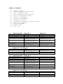
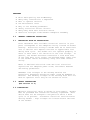
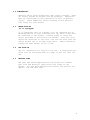
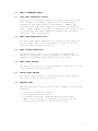
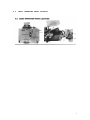
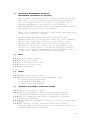
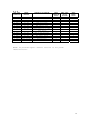
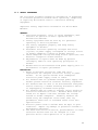
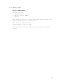
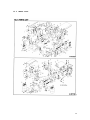
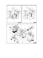
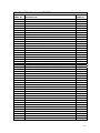
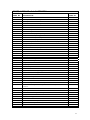
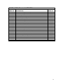
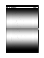
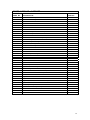
MICRO WELD
MODEL MD 4, 5 & 6
FLASH
BUTT WELDERS
MICRO PRODUCTS COMPANY
SERVICE MANUAL
1
TABLE OF CONTENTS
1.0
2.0
3.0
4.0
5.0
6.0
7.0
8.0
9.0
10.0
11.0
12.0
13.0
1.0
SPECIFICATIONS
GENERAL OPERATING INSTRUCTIONS
BASIC OPERATING PARTS
BASIC OPERATING PARTS LOCATION
TYPICAL OPERATING SEQUENCE
SPECIAL ADJUSTMENTS
PREVENTIVE MAINTENACE
SUGGESTED SETTINGS
DIAGNOISTIC CHART FOR TROULBE-SHOOTING
ELECTRICAL SCHEMATIC
SAFETY REMINDERS
BUYERS GUIDE
PARTS LIST
SPECIFICATIONS
Type of Welding Process
Welding Range
Material Suitability
Standard Operating Voltages
Maximum Line Demand 460 Volt
Maximum Line Demand 230 Volt
Single Phase AC Transformer
Clamp Method
Upset Method
Mounting
MODEL MD 4
Flash Weld
.250 to .750
Steel Rod
460/230 Volts
115amps@100% duty cycle
362amps@10% duty cycle
230amps@100% duty cycle
724amps@10% duty cycle
75 KVA @ 50% duty cycle
Pneumatic, Foot Controlled
Motor, Adjustable
4-Caster Wheels
MODEL MD5
Flash Weld
.500 to 1.125
Steel Rod
460/230 Volts
137 amps@100% duty cycle
433 amps@10% duty cycle
274 amps@100% duty cycle
866 amps@10% duty cycle
90 KVA @ 50% duty cycle
Pneumatic, Foot Controlled
Motor, Adjustable
4-Caster Wheels
Dimensions and Weights
Height Overall
Floor space
Welding Die Height
Weight
2.0
SPECIFICATIONS
Type of Welding Process
Welding Range
Material Suitability
Standard Operating Voltages
Maximum Line Demand 460 Volt
Maximum Line Demand 230 Volt
Single Phase AC Transformer
Clamp Method
Upset Method
Mounting
50 in.
50 in.
60 in. x 37 in.
43 in.
2025 LBS
60 in. x 37 in.
43 in.
2325 LBS
MODEL MD 6
Flash Weld
.750 to 1.500
Steel Rod
460/230 Volts
472amps@100% duty cycle
944amps@10% duty cycle
944amps@100% duty cycle
1888amps@10% duty cycle
308 KVA @ 50% duty cycle
Pneumatic, Foot Controlled
Motor, Adjustable
4-Caster Wheels
Dimensions and Weights
Height Overall
Floor space
50 in.
40 in. x 85 in.
Welding Die Height
Weight
44 in.
5400 LBS
2
FEATURES
•
•
•
•
•
•
•
•
Micro Weld quality and workmanship
Heavy-duty construction & components
East to operate controls
Low maintenance costs
Easy to set welding parameters
Safety electrical switch circuits
Heavy-duty weld heat selection switch
Sensitive straight slide movable headpiece assembly
2.0
GENERAL OPERATING INSTRUCIONS
2.1
ELECTRICAL HOOK-UP INSTRUCTIONS
First determine that available electrical service in your
plant corresponds to the nameplate rating located on welder
housing. Electrical wiring to welder must be of sufficient
size to deliver full ampere load with no appreciable loss
during weld cycle. The welder will not operate properly if
there is more than a 10% variation in the line voltage. In
general, the welder should be fused with a slow blow fuse
of the 100% duty cycle rating. The minimum power cable size
to the welder can be obtained by using this same current
rating.
Refer to National Electrical Code and local electrical
regulations for adequate power sizes; disconnect methods
and fusing guidelines.
Remember line voltages to the welding machine are
potentially dangerous should the power cords be damaged or
severed. The welding voltages at the welding dies will not
harm an operator since they do not exceed 10 volts.
2.2
SAFETY PRECAUTIONS
(See section 11.0)
2.2.1 ELECTRICAL
Maintain electrical cable to welder in good repair. Welder
must be grounded and connections securely tightened. Heat
Switch must not be changed to new position while a weld
cycle is in process. Disconnect electrical service before
serving welder – high voltages are located within the base
of the welder.
3
2.2.2 MECHANICAL
Operator while using welder must wear safety glasses. Keep
all safety guards on welders and use properly. Operators
must be instructed on basic operation of unit to prevent
injury. Check nameplate rating and keep within material
size range for each welder.
2.3
WATER-HOOK-UP
(if so equipped)
It is important that if a welder is to be operated for an
extended period of time and heads heat up, water lines must
be connected to the welder. Connect hoses to inlet and
outlet provided at the back of the welder. Shut-off valve
should be installed in the inlet line and the hose from the
outlet should run to an open sight drain. Water should be
turned off when welder is not in use.
2.4
AIR HOOK-UP
Set air regulators for from 20 to 80 lbs. A safety pop-off
valve will be activated when air gauge is set for over 100
lbs.
2.5
WELDING DIES
The dies and shoes supplied with the welder will handle
most size and material types within the range of the
welder. For new weld applications consult the factory for
special die and shoe sets.
4
3.0
BASIC OPERATING PARTS
3.1
WELD HEAT SELECTION SWITCH
Weld heat is selected by means of a heavy-duty tap switch
with 6 steps of voltage. The switch is conveniently
located on the lower front of the welder. Number one
indicates the high heat; number 6 indicates low welding
heat. Other numbers are equally graduated from high to low
to allow just the right amount of voltage for the weld
operation. (Not illustrated)
3.2
HEAD OPEN SPACE STOP BOLT
The head open space stop bolt is located on the top plate
in the right rear. This adjustment is used to set the
starting space between the dies.
3.3
HEAD CLOSED SPACE BOLT
The head closed space bolt is located on the movable
headpiece end plate. This adjustment is used to set the
closed or finishing space between the weld dies.
3.4
WELD LIMIT SWITCH
The weld limit switch is located behind a small door on the
lower right of the front panel.
3.5
MOTOR LIMIT SWITCH
The motor limit switch is located behind a small door on
the lower right of the front panel.
3.6
WELDING DIES
The welding dies (lower) and die shoes (upper), serve three
purposes:
1. To carry current for welding
2. To align two ends of stock
3. To prevent material slippage during a weld cycle.
Small rod is placed in the smaller grooves and the
larger rod is placed in the bigger grooves.
5
3.7
WELDER PUSHBUTTON OPERATING STATION
Four pushbutton switches make up the welder operating
station.
3.7.1 WELD BUTTON
This button activates all electrical circuits and initiates
the weld flash cycle after all safety devices have been
closed.
3.7.2 MOTOR BUTTON
This button activates the motor drive circuits only and is
used in adjusting welder spacing without activating the
weld transformer.
3.7.3 ANNEAL BUTTON
This button activates the manually operated anneal circuit
only.
3.7.4 STOP BUTTON
This button terminates all electrical cycles and can be
used with the motor button to aid in making welder
adjustments.
3.8
CLAMP ARMS
The clamp arms are air operated. The foot controlled air
valves are used to initiate the air clamp cylinders. The
foot valves are located at the bottom of the welder
housing. The right foot pedal operated the right clamp
arm, and the left pedal operates the left clamp arm. To
clamp stock, place it in the proper welding die groove and
press the top edges of the tilt pedal on foot valve. To
release stock, press on bottom edge of foot valve tilt
pedal. CAUTION: Care must be used when clamping stock, be
sure hands are clear of clamp arms. An air regulator with
gauge is located on the left end of the welder and should
be adjusted from 80-90 (PSI). Flow control valves are
factory installed to keep clamp arm movement slowed.
3.9
MOTOR SPEED CONTROL
The motor speed control is located on the right front
panel. A potentiometer located on the control box will
adjust the motor speed. A scale of 1-10 is found on the
potentiometer, 1 is slow and 10 is fast.
6
4.0
BASIC OPERATING PARTS LOCATION
7
5.0
TYPICAL SEQUENCE OF OPERATION
Wire to be joined must be free of rust, corrosion or other
insulating materials, clean wire where it makes contact
with welding dies. (Refer to section 8.0 for approximate
settings.)
5.1
Adjust head open space.
5.2
Adjust head closed space.
5.3
Adjust weld limit switch.
5.4
Adjust motor speed.
5.5
Pinch cut stock ends.
5.6
Place stock into welding dies so wire ends meet midway
between each welding die. Clamp into position with foot
valve pedals. After clamping the stock into position there
should be approximately 1/16” between stock ends.
5.7
Lower the flashguard to close the safety switch.
5.8
Press weld button firmly in and release.
5.9
Because of the amount of flashing it is advisable to step
back from machine.
5.10 Welder will finish the weld cycle without assistance.
5.11 Unclamp stock leaving weld burr intact.
5.12 Hard drawn stock, mild or high carbon steel will require an
anneal operation. (See 5.15)
5.13 Trim off weld burr so welded area is equal to parent
material diameter. Incomplete burr removal or undercutting
of the weld area will result in subsequent weld breaks.
5.14 ANNEAL OPERATION
An anneal cycle may be incorporated to process material for
improved bending qualities by placing welded stock into
anneal dies located on welder. This may be a standard
anneal device activated by a manual “Anneal Button” or an
accessory device that will automatically process the anneal
cycle, as explained below.
8
5.15 OPERATING INSTRUCTIONS –
PULSATING ANNEAL TIMER UNIT
To operate the pulsating anneal timer incorporated in the
Model MD-4, MD-5 and MD-6 welder, remove the weld from the
welding jaws and Reclamp the wire in the anneal jaws
located in front of welder. The weld burr should be placed
midway between the anneal jaws. Activate automatic anneal
operating switch located on front panel.
Before annealing a weld, it would be best to clamp a wire
the same size as the wire to be welded in the anneal jaws
as a test to determine the approximate timer settings. Set
the anneal heat switch one heat higher than that used to
weld the wire. Next, set top timer dial (total time) to
around 30 seconds and the On-Timer to two seconds and the
Off-Timer to two seconds. Depress and release anneal
switch. Timers will complete the time cycle and turn off.
If settings given above heat the wire too hot, any of these
three settings may be lowered: (A) Anneal heat switch
setting. (B) Overall time. (C) Time on.
If setting does not heat the rod up enough, increase any
one or more of the settings mentioned above. The Off-Time
is used to allow heat pulses to spread out into the wire
being heated. The ideal settings are those that cause the
temperature to rise gradually to the correct anneal
temperature and then cut off.
Variations in the temperature from one time to another can
be caused by not starting with approximately the same rod
temperature or variations in electrical contact between the
rod and anneal jaw. Once settings have been determined for
a particular size and alloy, a chart can be made so they
may be repeated.
9
6.0
SPECIAL ADJUSTMENTS
6.1
HEAT SWITCH SETTINGS
This setting determines the amount of heat available for
welding. In general use higher heat settings for larger
stock and lower heat settings for smaller stock. Number
one heat is the highest setting and number six heat is the
lowest heat.
6.2
HEADPIECE CLOSED SPACE
The closed space bolt should be adjusted to equal the
diameter of the rod as measured between the dies at the
groove being used to weld that particular stock size. The
closed space should be set prior to setting the open space
adjustment. Refer to Figure 4 for this setting.
6.3
HEADPIECE OPEN SPACE
The headpiece open space is adjusted by a bolt that pushes
against the lazy arm. (See Figure 5.) This setting must be
made after setting the closed space adjustment. Use the
method described in Figure 5 to establish the proper open
space.
6.3.1 On the MD-6 Model, please refer to figures 1-5 in
conjunction with Section 10, Print #B-5809.
10
6.4
WELD LIMIT SWITCH
The weld limit switch adjustment will either increase or
decrease the time of the heat cycle during the weld cycle.
Determine which quadrant to change; a single winged nut
maintains the quadrant position. Loosening this nut will
enable the quadrant to be changed to a new position on a
graduated scale etched on the quadrant. (Refer to Figures 1
& 2.) (Also refer to Section 8.0 for approximate setting.)
6.5
MOTOR LIMIT SETTING
The motor limit switch quadrant is factory preset and
should not need field adjustment. But if this ever needs
adjustment—Determine which quadrant to change; a single
winged nut maintains the quadrant position. Loosening this
nut will enable the quadrant to be changed to a new
position on a graduated scale etched on the quadrant.
(Refer to Figure 1.)
6.6
DRIVE MOTOR ADJUSTMENT
(DC Drive is Standard/AC Drive is Optional)
This adjustment is made by turning a potentiometer on the
front of the welder. A graduated scale of 1-10 is located
on the potentiometer. #1 is slowest speed and is used for
larger stock. During a weld cycle, there should be
flashing when the ends of stock begin to touch and until
the cam insert engages the lazy arm roller. If this does
not happen, refer to Section 9.0.
11
12
13
7.0
PREVENTIVE MAINTENANCE TECHNIQUE
MAINTENANCE PROCEDURES AS REQUIRED
Keep in mind that these welders are precision built to last
many years, but will require good maintenance procedures.
They are designed to be as automatic as possible with a
minimum dependence on the ability of the operator.
Adjustments must be made by those thoroughly familiar with
the operating principles of the welders.
Brush loose flashings from dies, clamp shoes and flash tray
to prevent excessive build-up.
Check welding die shoes and dies for excessive wear.
Replace both sets if they become excessively worn. Welding
dies in poor condition is primary cause of poor welds.
Welding die notes: Remove dies and clean or replace as
necessary. By placing welding dies on fine emery cloth
located on a flat surface, dies may be brightly polished.
Brighten die seats on headpieces by placing emery cloth on
a flat file. Replace dies and pull down tightly.
7.1
DAILY
7.1.1 Check for water leaks.
7.1.2 Check for air leaks.
7.1.3 Drain airline filter bowl.
7.1.4 Tighten any loose parts.
7.1.5 Clean flash pan.
7.2
WEEKLY
7.2.1 Repeat above service items
7.2.2 Grease following places with hand grease gun:
A. Clamp arm pivot bearings.
B. Headpiece slide bearings
C. Upset lever arm bearing.
7.3
QUARTERLY-DISCONNECT POWER FROM WELDER
7.3.1 Repeat above service items.
7.3.2 Tighten transformer clamp retaining ring to prevent
transformer laminations from vibrating out of place.
7.3.3 Blow all flashings from top of transformer to prevent
shorting of secondary.
7.3.4 Check contacts on magnetic contactor, replace if worn badly
burned.
7.3.5 Wash contacts on heat selection switch with carbon
tetrachloride, dry with a clean cloth and place a thin coat
of petroleum jelly on contacts.
14
7.4
ANNUALLY – DISCONNECT POWER FROM WELDER
7.4.1 Repeat above service items.
7.4.2 Check for wear in clamp arm bearings, replace when needed.
7.4.3 Check for excessive headpiece wear (die seats not lining up
properly).
7.4.4 Check pop safety valve on air system to be sure they are
operative.
7.4.5 Clean inside of welder housing.
7.5
WELDING DIES AND DIE SHOES INFORMATION
Description:
Welding dies – Lower conducting electrode and clamp jaw.
Welding die shoes – Upper clamping member.
Welding dies and die shoes in poor condition are the main
causes of bad welds.
CARE OF DIE SETS:
7.5.1 Use a brass or fiber blade to remove particles of flashings
that build-up on die sets. Excessive flash build-up causes
die burns on material and shorting of die sets.
7.5.2 Do not attempt to clamp material that is not suited for
welder into die sets. Undersize materials will slip and
burn die grooves, oversize materials will overstress
clamping parts.
7.5.3 Do not use welding die sets for a vise.
not withstand the mechanical abuse.
These parts will
7.5.4 Whenever welding dies are replaced, clean bottoms of dies
and corresponding die seats to a bright and clean condition
before bolting them tightly into place. An oxidized
surface will insulate the welding dies and reduce effective
welding voltage.
7.5.5 Welding die shoes must swivel freely within clamp arm
pivots to prevent cracking of die shoes. File down die shoe
boss if necessary.
7.5.6 Welding die set will wear with use and must be changed
occasionally for good welding results. Keep and adequate
supply of replacement parts available. Wire and rod
slippage is a problem caused by poor die sets and a major
cause of wire breaks.
15
7.6
RECOMMENDED SHEAT CUTS FOR WELDERS
8.0
SUGGESTED SETTINGS
MATERIAL
SIZE
MD-4 .250-.750
Steel
¼” Dia
Steel
3/8” Dia
Steel
½” Dia
Steel
5/8” Dia
Steel
¾” Dia
MD-5 .500-1.125
Steel
½” Dia
Steel
¾” Dia
Steel
1” Dia
Steel
1 1/8” Dia
MD-6 .500-1.500
Steel
9/16” Dia
Steel
5/8” Dia
Steel
¾” Dia
Steel
1” Dia
Steel
1 1/8” Dia
Steel
1 1/8” Dia
Steel
1 ½” Dia
STARTING
SPACE
BETWEEN
DIES
WELD
HEAT
FLASHING
SPEED
WELD LIMIT
SWITCH
SETTING
6
5
5
4
2
100%
90%
80%
70%
70%
1
1
1
4
4
6
5
2
1
100%
100%
60%
60%
1 ½
2
2 ¾
2 ¾
1 3/8”
1 3/8”
1 ¾”
1 ¾”
Front
Front
Rear
Rear
100 PSI
100 PSI
100 PSI
100
PSSSI
6
6
6
4
4
4
2
100%
100%
90%
70%
65%
60%
50%
4 ¼
4 ¼
4 ¼
3
3
2
1
2 1/8”
2 1/8”
2 1/8”
3”
3”
3”
3 ¼”
Front
Front
Front
Rear
Rear
Rear
Rear
100
100
100
100
100
65
90
1
1
1
1
1
½”
½”
½”
¾”
¾”
GROOVE
CLAMP
PRESSURE
Front
Middle
Middle
Rear
Rear
100
100
100
100
100
PSI
PSI
PSI
PSI
PSI
PSI
PSI
PSI
PSI
PSI
PSI
PSI
16
9.0
DIAGNOSTIC CHART FOR TROUBLE-SHOOTING
WELDING ACTION
Starts flashing but cycle
is broken and weld, if
any, has large push-up or
weld may pull apart.
CAUSE
Weld heat too low
Upset speed too fast for
welding heat
Flashing cycle too long
for stock size
Does not start flashing,
makes big burr or hot
metal drops out before
weld cycle is complete
Weld cycle normal-yet
voids found in weld
Ends of stock too blunt
Weld action normal until
upset occurs then welder
stalls
Weld heat too low
Weld limit switch set to
hold on too long
Lack of shims under upset
cam
Pinch cut on rod too
tapered or flashing cycle
is too short
Too much shim thickness
under upset cam
Flashing cycle too short
Weld burns on stock
Dirty stock causing poor
contact between die and
material
Weld limit switch set to
hold on too long
Too much heat stored in
rod during flashing
Flashing speed too slow
or weld heat too hot
Dirty stock
Variations in welding
Dirty dies
Loose upset cam
Flashing and weld cycle
seem normal but weld is
pulled apart while hot
Input voltage variations
Misalignment of rods
Loose welding die or
transformer secondary
connection
Worn die grooves
Starting gap between dies
too great
Loose headpiece slide
shafts
Ends or rod bent
REMEDY
Increase weld heat
Slow down flash cycle
Allow small space between
ends of stock when placed
in welding dies
Grind or cut stock to
chisel point
Increase weld heat or
slow down upset speed
Increase weld heat or
slow down upset speed
Add extra shims under
upset cam (1/32” at a
time)
Change angle of rod cut
or adjust for longer
flash cycle
Remove some of upset cam
shims
Decrease flashing speed
or increase weld heat
Clean scale or rust from
stock
Readjust limit switch to
cut out sooner
Space ends apart to
shorten flash cycle
Increase flashing speed
Remove rod scale before
welding
Wire brush die grooves
Tighten cam-check locking
key
Check input voltage only
5% drop permissible
Clean and tighten
secondary connections
Replace dies
Reduce starting space
either with motor limit
switch or space adjusting
screw
Return to factory for recementing
Straighten 6” of material
where rod meets dies
17
9.1
ELECTRICAL TROUBLE-SHOOTING OF WELDER
(Caution!! Extreme care should be exercised when making
these tests. Dangerous voltages are present in the welder.
Only persons familiar with electrical safety precautions
should perform these tests.)
9.1.1 TROUBLE-SHOOTING TABLE
(See section 9.1.3)
This electrical trouble-shooting table is furnished as a
suggested method of trouble-shooting the welder. The
individual steps of the table should be performed in the
order given, to make the tests valid. The electrical
schematic (section 10) furnished for these tests show the
table test points. The table may be used for welders with
a different but closely related wiring by using
corresponding test points. During all tests, line voltage
should be connected to L1 & L2 of the welder. The heat
switch should be set to the #1 position.
9.1.2 FINAL ELECTRICAL CHECKS
Set the heat switch to the number 1 position, connect the
voltmeter across the welding dies. Press the operating
switch. The meter reading will typically be less than 10
VAC. Consult the weld specification sheet for this value.
Rotate the heat switch through all settings. If the
voltage is not read at any setting, the heat switch may be
defective. Actuate the weld limit switch; observe the
reading goes to zero. Release the weld limit and operating
switches, the reading should remain at zero.
18
9.1.3
TEST LEAD
CONNECTION
X1 X2
X2 FU1-1
X2 FU1-2
X2 LS3-2
X2 PB1-2
X2 LS1-2
X2 Ls1-2
X2 PB3-2
X2 LS2—1
X2
X2
X2
X2
L2
L2
L2
LS2-2
CRW-2
PB4-1
PB4-2
CRW-3
CRW-4
T1-1
METER
READING
115
115
115
115
115
115
115
115
115
VAC
VAC
VAC
VAC
VAC
VAC
VAC
VAC
VAC
115 VAC
115 VAC
115 VAC
115 VAC
Line voltage
Line voltage
Line voltage
PROBLEM IF NO READING
Bad control transformer
Bad fuse connection
Open fuse
Open flashguard switch
Open stop switch
LS1 open
CRM contacts open
Bad weld switch
Open connection to weld
limit switch
Open weld limit switch
PB4 or CRW defective
Open wire to anneal switch
Bad anneal switch
Open wiring to contactor
Bad contactor
Open wire to heat switch
PRESS
OPERATING
SWITCH
WELD LIMIT
SWITCH
ACTUATED
PRESS
ANNEAL
SWITCH
X
X
X
X
X
X
NOTE: To perform repair consult section 13 for parts
identification.
19
10.0 ELECTRICAL SCHEMATIC
20
21
22
23
24
25
11.0 SAFETY REMINDERS
The following accident prevention information is presented
to eliminate potential hazards while operating, inspecting
or repairing Micro-Weld electric resistance welding
equipment.
Important safety compliance information for Micro-Weld
Welders.
GENERAL
1. Qualified personnel, prior to using equipment, must
instruct an operator on basic operation and
malfunction methods.
2. Safety eyeglasses must be worn by all personnel
operating or servicing welders.
3. Use safety equipment properly and keep safety
equipment on welders.
4. Determine that both operating voltages and hertz
(cycles) of power supply correspond to ratings listed
on welder nameplate located on welder housing.
5. Check nameplate ratings and keep within capacities and
material categories stated therein.
6. Adjustments or repairs must be made by persons
thoroughly familiar with operating principles of
welder.
7. Welder must be disconnected from power supply prior to
maintenance or repair procedures.
ELECTRICAL
1. Refer to National Electrical Code and local
regulations for adequate electrical wiring to power
welder. Do not operate welder with inadequate
electrical power supply cords or cable.
2. All welders must be grounded through power supply and
welder ground connection terminal securely tightened.
3. All welders must be able to be disconnected from power
source either by a double breaking disconnect switch
or unplugged by standard rated plugs.
4. All welders must be fused to prevent injury should an
electrical malfunction occur. Welders must never be
fused for an ampere load that exceeds the ratings
stated on welder nameplate. Normally welders are
fused using the nameplate rated load; time lag
parameters functional to standard fuses allow this
specification.
5. Electric power cords to welder must be kept in good
condition. Report any damage or potential hazards to
maintenance personnel.
6. The weld heat selection switch, potentiometer or range
selection devices must not be changed to a new
position while a weld operation is in process.
26
12.0 BUYERS GUIDE
HOW TO ORDER PARTS:
You must provide
1. Machine Model
2. Machine Serial Number
3. Voltage
Then identify part(s) on part list (last page in book) and
provide MICRO with the circled number.
CALL MICRO at 800-872-1068
OR FAX MICRO at 630-787-9360
Provide MICRO with your company name and purchase order
number.
27
13.0 PARTS LIST
28
29
PARTS LIST MD 4 & 5 WELDERS
MODEL/
PART NO
MD-01A
MD-01B
MD-04
MD-04A
MD-05
MD-08L
MD-08R
MD-08AL
MD-08AR
MD-09
MD-10
MD-11
MD-12
MD-12A
MD-12B
MD-12C
MD-13
MD-13A
MD-14
MD-20
MD-21
MD-22
MD-23
MD-25
MD-26
MD-27
MD-30
MD-31
MD-32
MD-33
MD-35
MD-36
MD-37
MD-38
MD-39
MD-40
MD-41
MD-43
MD-44
MD-45
MD-46
MD-47
MD-47H
MD-48
MD-48H
MD-49
DESCRIPTION
Basic head assembly
Complete head assembly, no dies, no shoes
Shaft wipes, felt
Shaft wipe retaining ring
Head return spring
Clamp arm, left
Clamp arm, right
Clamp arm for arm anneal, left
Clamp arm for arm anneal, right
Arm pivot pin, steel
Arm pin washer
Grease zerk 90 degrees
Clamp cylinder #50
Cylinder replacement diaphragm
Cylinder shaft boot
Clamp cylinder clevis
Foot pedal, clamp
Hand operated clamp valve
Pedal mount screw
End plate stationary head
End plate mount bolt
End plate movable head
End plate mount bolt, movable head
Closed head space adjusting screw
End plate insulation
Muffler
Stationary anneal extension bar
Front anneal bar
Anneal bar mount bolts
Movable anneal extension bar
CA anneal clamp, each (front)
CAL anneal, pair
Anneal clamp mount bolt
Arm anneal die set (4 pieces)
Anneal die mount screw
Complete truck
Truck door
Swivel caster
Stationary caster, special order
#4 shear
Shear mount bolt
Standard vise
Heavy duty vise
Standard vise bracket
Heavy duty vise bracket
Vise bracket mount bolt
ITEM NO.
30654
30661
30640
48219
80059
30554
30614
30643
30644
30526
30517
48422
77706
77713
77718
77727
77859
77864
90611
30548
90687
40551
90203
30523
30641
77892
62079
62080
90260
62081
62155
62020
90260
30524
90617
40571
40540
48108
48117
64009
90295
78112
78111
60022
60005
90295
30
PARTS LIST MD 4 & 5 WELDERS
MODEL/
PART NO
MD-50
MD-51
MD-52
MD-53
MD-54
MD-55
MD-56
MF-57
MD-58R2
MD-58V2C
MD-58V2A
MD-60R
MD-60S
MD-60SL
MD-60SR
MD-62S
MD-62SA
MD-62SL
MD-62SR
MD-62SS
MD-63S
MD-64
MD-65
MD-70F
MD-70FP
MD-70FS
MD-70S
MD-71U
MD-71L
MD-72
MD-78
TS-06
MD-82
MD-83A
MD-83C
MD-87
MD-88
MMD-89
MD-120B
MD-121B
MD-121C
MD-122B
MD-123B
MD-124B
MD-125B
DESCRIPTION
Vise mount bolt
Flashguard assembly
Flashguard mount bolt
Flash shield safety switch
Upset cover
Upset cover mount screw
Flash tray
Flash tray mount bolt
Contour dies, pair, 3 grooves
Standard dies, copper
Standard dies, alloy
Contour shoes, pair
Shoes complete w/inserts insulation, pair
Shoe, left
Shoe, right
Set of inserts (4 pieces)
Insert screw
Left insert
Right insert
Straight insert
Insulation for shoes (set)
Shoe attaching bolt
Die attaching bolt
Complete transformer
Primary
Secondary
Shunt
Transformer ring, upper
Transformer ring, lower
Transformer studs
Control step down transformer
6 point heat switch
Heat switch mount bolt
Contactor, state voltage & Serial number
Contactor repair kit, state voltage & serial
number
Terminal block
3 stage anneal timer
Anneal timer operating switch
Upset cam with insert
Insert only, for cam
Insert shim
Insert attaching screw
Upset leverage bar w/roller
Roller
Roller axle
ITEM NO.
90262
30656
30672
57813
30551
90656
40500
90202
30662
30594
30618
30673
30660
30542
30543
30659
90703
30536
30537
30535
30671
90664
90657
50558
50569
50515
50527
50506
50535
50521
59525
56549
90294
57611
APPL
53000
50572
57810
30667
30529
30530
90619
30530
30521
30520
31
PARTS LIST MD 4 & 5 WELDERS
MODEL/
PART NO
MD-126B
MD-127B
MD-128B
MD-129
MD-129A
MD-130B
MD-131B
MD-132B
MD-133B
MD-134B
MD-135B
MD-136B
MD-137B
MD-138
DESCRIPTION
Pivot bushing, leverage bar
Pivot bushing bolt
Open stop bolt
Quadrant mount plate
Quadrant plate spacers
Weld switch quadrant
Motor switch quadrant
Quadrant mount bolt
Quadrant switch lever
Lever mount bolt
Cutoff cam switch
Cutoff cam set screw
Cutoff cam spacer
Limit & motor cutoff switch
ITEM NO.
30522
90687
90040
50529
40608
50508
50510
90021
30525
90262
30532
90015
30534
57813
MD-157
MD-158
MD-159
Thyrite resistor
4 button operating station
Flow control valve
58132
57854
778/62
MD-500
MD-501
DC motor control
Gear reducer w/motor n.s.
57734
40616
32
PARTS LIST MD 6 WELDER
MODEL/
PART NO
MD-01B
MD-01A
MD-04
MD-07
MD-07A
MD-08
MD-08A
MD-09
MD-10
MD-10A
MD-10B
MD-10C
MD-16MD2
MD-16MD3
MD-MD60S
MD-19
MD-19A
MD-20
MD-20A
MD-20B
MD-20C
MD-20D
MD-08B
MD-21
MD-22
MD-23
MD-24
MD-24A
MD-24B
MD-24C
MD-26
MD-27
MD-27A
MD-27B
MD-28
MD-29
MD-30
MD-31
MD-32
MD-36
MD-36A
MD-37
MD-38
MD-38A
MD-38B
MD-39C
DESCRIPTION
Basic head assembly, with shafts & shields
Stationary head attaching bolts
Head return spring
Clamp arm pivot pin
Bell crank pivot pin
Left clamp arm
Right clamp arm
Clamp eccentric leveling block
Bell crank
Bell crank block pin
Bell crank block
Bell crank retaining screw
Standard copper dies 2 V groove
Standard copper dies 3 V groove
Die shoes, standard
Shoe attaching screw washer
Attaching screw insulating washer
Shoe attaching screw
Shoe screw insulating tube
Shoe boss insulating washer
Shoe boss insulating ring
Shoe insulating plate
Arm insulating spacer
Die attaching screw
Movable head end plate
End plate insulation
Secondary shunt
Shunt clamp plates
Shunt attaching screws, long (14)
Shunt attaching screws, short (4)
Open space adjustment screw
Upset pressure plate
Upset plate mount screw
Upset plate insulation (optional)
End plate mount screws
Anneal mount bracket
Weld transformer
Primary coil
Transformer secondary
Clamp cylinder stud
Cylinder stud nuts
Clamp link stop block
Clamp cylinder
Clamp cylinder clevis
Clamp cylinder boot
Clamp cylinder clevis
ITEM NO.
30067
90683
80059
30014
30015
30080
30081
70005
70007
70010
70004
90665
30060
30059
30065
30068
30068
90691
30069
30070
30071
30072
30073
90689
30074
30075
50004
50000
90330
90329
30000
30076
90661
30077
90660
30058
50005
50016
50017
70001
92066
70002
77707
77714
77719
70009
33
PARTS LIST MD 6 WELDER
MODEL/
PART NO
MD-120
MD-120A
MD-121
MD-122
MD-123
MD-124
MD-125
MD-126
MD-127
MD-48
MD-49
MD-129
MD-129A
MD-130A
MD-130B
MD-131
MD-133
MD-134
MD-135
MD-136
MD-137
MD-138
MD-139
MD-140
MD-141
MD-142
MD-25
MD-25A
MD-25B
DESCRIPTION
Upset cam only
Upset cam complete
Upset cam insert
Upset cam shim
Upset lever bar
Lever bar rollers
Axle for roller
Lever bar pivot bushing
Lever bar pivot bolt
Upset cover
Head return assist spring
Quadrant plate
Quadrant plate spacer
Weld switch quadrant (limit)
Motor switch quadrant
Quadrant mount bolt
Quadrant switch lever
Switch lever mount bolt
Switch operating cam
Cam set screw
Cam spacer
Limit & motor switch
Motor 3 H.P.
Speed reducer
Motor sprocket
Speed reducer sprocket
3/8” ship for closed stop
5/16” shim for closed stop
¼” shim for closed stop
D.C. motor control
4 push button control station
Thyrite resistor
8 point heat switch 300 amp
Speed reducer
Motor pulley
Speed reducer pulley
Chain
Belt
ITEM NO.
30083
30085
30084
30086
30087
30521
30510
30522
90687
40618
80045
30679
40608
50508
50510
90217
30525
90262
30532
90015
30534
57813
57743
57746
APPL
APPL
30676
30678
30678
57736
57854
57676
57857
57746
APPL
APPL
APPL
APPL
34