1
SERVICE MANUAL
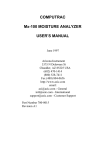
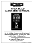
TRAULSEN G SERIES
FREEZER
G12000 Model Series
G22000 Model Series
G31300 Model Series
G22010 MODEL SHOWN
This Manual is prepared for the use of trained Hobart Service Technicians
and should not be used by those not properly qualified.
This manual is not intended to be all encompassing. If you have not
attended a Hobart Service School for this product, you should read, in its
entirety, the repair procedure you wish to perform to determine if you
have the necessary tools, instruments and skills required to perform the
procedure. Procedures for which you do not have the necessary tools,
instruments and skills should be performed by a trained Hobart Service
Technician.
The reproduction, transfer, sale or other use of this Manual, without the
express written consent of Hobart, is prohibited.
This manual has been provided to you by ITW Food Equipment Group LLC
("ITW FEG") without charge and remains the property of ITW FEG, and by
accepting this manual you agree that you will return it to ITW FEG
promptly upon its request at any time in the future.
A product of TRAULSEN
Fort Worth, TX 76106-1988
F25393 (August 2010)
G SERIES FREEZER
TABLE OF CONTENTS
GENERAL . . . . . . . . . . . . . . . . . . . . . . . . . . . . . . . . . . . . . . . . . . . . . . . . . . . . . . . . . . . . . . . . . . . . . . . . . . . . . . . . . . . . . . . . . 3
Introduction . . . . . . . . . . . . . . . . . . . . . . . . . . . . . . . . . . . . . . . . . . . . . . . . . . . . . . . . . . . . . . . . . . . . . . . . . . . . . . . . . . . . 3
Location . . . . . . . . . . . . . . . . . . . . . . . . . . . . . . . . . . . . . . . . . . . . . . . . . . . . . . . . . . . . . . . . . . . . . . . . . . . . . . . . . . . . . . . 3
Operation . . . . . . . . . . . . . . . . . . . . . . . . . . . . . . . . . . . . . . . . . . . . . . . . . . . . . . . . . . . . . . . . . . . . . . . . . . . . . . . . . . . . . . 3
Cleaning . . . . . . . . . . . . . . . . . . . . . . . . . . . . . . . . . . . . . . . . . . . . . . . . . . . . . . . . . . . . . . . . . . . . . . . . . . . . . . . . . . . . . . . 3
Tools . . . . . . . . . . . . . . . . . . . . . . . . . . . . . . . . . . . . . . . . . . . . . . . . . . . . . . . . . . . . . . . . . . . . . . . . . . . . . . . . . . . . . . . . . 3
Control Panel . . . . . . . . . . . . . . . . . . . . . . . . . . . . . . . . . . . . . . . . . . . . . . . . . . . . . . . . . . . . . . . . . . . . . . . . . . . . . . . . . . . 4
Specifications . . . . . . . . . . . . . . . . . . . . . . . . . . . . . . . . . . . . . . . . . . . . . . . . . . . . . . . . . . . . . . . . . . . . . . . . . . . . . . . . . . . 4
REMOVAL AND REPLACEMENT OF PARTS . . . . . . . . . . . . . . . . . . . . . . . . . . . . . . . . . . . . . . . . . . . . . . . . . . . . . . . . . . . . . . 6
Covers & Panels . . . . . . . . . . . . . . . . . . . . . . . . . . . . . . . . . . . . . . . . . . . . . . . . . . . . . . . . . . . . . . . . . . . . . . . . . . . . . . . . 6
Cabinet Lamp . . . . . . . . . . . . . . . . . . . . . . . . . . . . . . . . . . . . . . . . . . . . . . . . . . . . . . . . . . . . . . . . . . . . . . . . . . . . . . . . . . . 7
Intela-traul Control . . . . . . . . . . . . . . . . . . . . . . . . . . . . . . . . . . . . . . . . . . . . . . . . . . . . . . . . . . . . . . . . . . . . . . . . . . . . . . . 8
Intela-traul Relay Module . . . . . . . . . . . . . . . . . . . . . . . . . . . . . . . . . . . . . . . . . . . . . . . . . . . . . . . . . . . . . . . . . . . . . . . . . . 8
Compressor Relay . . . . . . . . . . . . . . . . . . . . . . . . . . . . . . . . . . . . . . . . . . . . . . . . . . . . . . . . . . . . . . . . . . . . . . . . . . . . . . . 9
Cabinet Air Sensor . . . . . . . . . . . . . . . . . . . . . . . . . . . . . . . . . . . . . . . . . . . . . . . . . . . . . . . . . . . . . . . . . . . . . . . . . . . . . . . 9
Evaporator Coil Sensor . . . . . . . . . . . . . . . . . . . . . . . . . . . . . . . . . . . . . . . . . . . . . . . . . . . . . . . . . . . . . . . . . . . . . . . . . . 10
Thermal Expansion Valve . . . . . . . . . . . . . . . . . . . . . . . . . . . . . . . . . . . . . . . . . . . . . . . . . . . . . . . . . . . . . . . . . . . . . . . . 10
Evaporator Coil / Defrost Heater . . . . . . . . . . . . . . . . . . . . . . . . . . . . . . . . . . . . . . . . . . . . . . . . . . . . . . . . . . . . . . . . . . . 11
Door Gasket . . . . . . . . . . . . . . . . . . . . . . . . . . . . . . . . . . . . . . . . . . . . . . . . . . . . . . . . . . . . . . . . . . . . . . . . . . . . . . . . . . . 11
Door Assembly . . . . . . . . . . . . . . . . . . . . . . . . . . . . . . . . . . . . . . . . . . . . . . . . . . . . . . . . . . . . . . . . . . . . . . . . . . . . . . . . . 12
Evaporator Fan . . . . . . . . . . . . . . . . . . . . . . . . . . . . . . . . . . . . . . . . . . . . . . . . . . . . . . . . . . . . . . . . . . . . . . . . . . . . . . . . 12
Condensing Unit Components . . . . . . . . . . . . . . . . . . . . . . . . . . . . . . . . . . . . . . . . . . . . . . . . . . . . . . . . . . . . . . . . . . . . . 13
Hot Gas Condensate Pan . . . . . . . . . . . . . . . . . . . . . . . . . . . . . . . . . . . . . . . . . . . . . . . . . . . . . . . . . . . . . . . . . . . . . . . . 14
SERVICE PROCEDURES AND ADJUSTMENTS . . . . . . . . . . . . . . . . . . . . . . . . . . . . . . . . . . . . . . . . . . . . . . . . . . . . . . . . . . 15
Check Refrigerant Charge (Superheat, Sub Cooling & Split Temperatures) . . . . . . . . . . . . . . . . . . . . . . . . . . . . . . . . . . 15
Checking for Leaks . . . . . . . . . . . . . . . . . . . . . . . . . . . . . . . . . . . . . . . . . . . . . . . . . . . . . . . . . . . . . . . . . . . . . . . . . . . . . 16
Evacuating System . . . . . . . . . . . . . . . . . . . . . . . . . . . . . . . . . . . . . . . . . . . . . . . . . . . . . . . . . . . . . . . . . . . . . . . . . . . . . 17
Charging System . . . . . . . . . . . . . . . . . . . . . . . . . . . . . . . . . . . . . . . . . . . . . . . . . . . . . . . . . . . . . . . . . . . . . . . . . . . . . . . 17
System Clean up . . . . . . . . . . . . . . . . . . . . . . . . . . . . . . . . . . . . . . . . . . . . . . . . . . . . . . . . . . . . . . . . . . . . . . . . . . . . . . . 17
Software Version . . . . . . . . . . . . . . . . . . . . . . . . . . . . . . . . . . . . . . . . . . . . . . . . . . . . . . . . . . . . . . . . . . . . . . . . . . . . . . . 18
Control Calibration . . . . . . . . . . . . . . . . . . . . . . . . . . . . . . . . . . . . . . . . . . . . . . . . . . . . . . . . . . . . . . . . . . . . . . . . . . . . . . 18
Control Parameters . . . . . . . . . . . . . . . . . . . . . . . . . . . . . . . . . . . . . . . . . . . . . . . . . . . . . . . . . . . . . . . . . . . . . . . . . . . . . 19
Evaporator Coil Sensor Test . . . . . . . . . . . . . . . . . . . . . . . . . . . . . . . . . . . . . . . . . . . . . . . . . . . . . . . . . . . . . . . . . . . . . . 22
Cabinet Air Sensor Test . . . . . . . . . . . . . . . . . . . . . . . . . . . . . . . . . . . . . . . . . . . . . . . . . . . . . . . . . . . . . . . . . . . . . . . . . . 22
Cabinet Air, Cabinet Coil,
& Sensor Resistance Test . . . . . . . . . . . . . . . . . . . . . . . . . . . . . . . . . . . . . . . . . . . . . . . . . . . . . . . . . . . . . . . . . . . . 22
Compressor Relay Test . . . . . . . . . . . . . . . . . . . . . . . . . . . . . . . . . . . . . . . . . . . . . . . . . . . . . . . . . . . . . . . . . . . . . . . . . . 22
Door Switch Test . . . . . . . . . . . . . . . . . . . . . . . . . . . . . . . . . . . . . . . . . . . . . . . . . . . . . . . . . . . . . . . . . . . . . . . . . . . . . . . 22
ELECTRICAL OPERATION . . . . . . . . . . . . . . . . . . . . . . . . . . . . . . . . . . . . . . . . . . . . . . . . . . . . . . . . . . . . . . . . . . . . . . . . . . . 23
Component Function . . . . . . . . . . . . . . . . . . . . . . . . . . . . . . . . . . . . . . . . . . . . . . . . . . . . . . . . . . . . . . . . . . . . . . . . . . . . 23
Sequence of Operation . . . . . . . . . . . . . . . . . . . . . . . . . . . . . . . . . . . . . . . . . . . . . . . . . . . . . . . . . . . . . . . . . . . . . . . . . . 24
Component Location . . . . . . . . . . . . . . . . . . . . . . . . . . . . . . . . . . . . . . . . . . . . . . . . . . . . . . . . . . . . . . . . . . . . . . . . . . . . 25
Wiring Diagrams . . . . . . . . . . . . . . . . . . . . . . . . . . . . . . . . . . . . . . . . . . . . . . . . . . . . . . . . . . . . . . . . . . . . . . . . . . . . . . . . 26
TROUBLESHOOTING . . . . . . . . . . . . . . . . . . . . . . . . . . . . . . . . . . . . . . . . . . . . . . . . . . . . . . . . . . . . . . . . . . . . . . . . . . . . . . . 28
© Hobart 2010
F25393 (August 2010)
Page 2 of 32
G SERIES FREEZER - GENERAL
GENERAL
INTRODUCTION
CLEANING
General
All G series freezers are Energy Star efficient and
include a wide range of one, two, & three sectional
reach in freezers. All models are capable of -10EF in
up to 90EF ambient. The cabinets are equipped with
anti-condensate door perimeter heaters.
These units aid in preserving food quality, texture
and nutritional value.
All of the information, illustrations and specifications
contained in this manual are based on the latest
product information available at the time of printing.
LOCATION
Refer to the Installation Instructions for specific
location requirements.
OPERATION
Refer to the Operation Manual for specific operating
instructions.
Refer to the Operation Manual for specific cleaning
instructions. The condenser coil must be cleaned
every six months. This can be done with a vacuum
cleaner using a fin comb or condenser coil brush.
TOOLS
•
Standard set of hand tools
•
Clamp meter Part No. 00-541069 Grainger No.
1ND81 or equivalent
•
Grounding kit - Static Control Kit Grainger No.
4KK44
•
Micro amp meter
•
VOM with AC current tester (sensitivity of at
least 20,000 ohms per volt)
•
Refrigeration tool kit Part No. 00-913093-15
•
Digital thermometer with quad inputs Model
DT304 Part No. 00-913093-12
•
Inficon D-Tek Select refrigerant leak detector
Part No. 00-913093-2
•
Vacuum Cleaner - Shop Vac
•
Fin comb Grainger Part No. 2YJ78 or equivalent
•
Condenser coil brush Grainger Part No. 3HHE8
or equivalent
Page 3 of 32
F25393 (August 2010)
G SERIES FREEZER - GENERAL
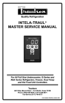
CONTROL PANEL
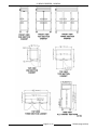
SPECIFICATIONS
DIMENSIONS
1 Section Cabinet
2 Section Cabinet
3 Section Cabinet
Height- overall on casters
83-1/4" (211.46cm)
83- 1/4" (211.46cm)
83- 1/4" (211.46cm)
Width
29- 7/8" (75.9cm)
52- 1/8" (132.4cm)
76- 5/16" (193.8cm)
Depth
35" (88.8cm)
35" (88.8cm)
35" (88.8cm)
24.2
46.0
69.1
Net Capacity cu. ft.
F25393 (August 2010)
Page 4 of 32
G SERIES FREEZER - GENERAL
Page 5 of 32
F25393 (August 2010)
G SERIES FREEZER - REMOVAL AND REPLACEMENT OF PARTS
DATA
1 Section Cabinet
2 Section Cabinet
3 Section Cabinet
3 Section Cabinet
115/60/1
115/60/1
115/60/1
208/60/1
Amps Full Load
9.5
11.2
16.0
11.0
OPERATING DATA
1 Section Cabinet
2 Section Cabinet
3 Section Cabinet
R-404A
R-404A
R-404A
500
500
500
250
250
250
1930 @ -20EF Evaporator
Temp. & 90EF Ambient
2970 @-20EF Evaporator
Temp. & 90EF Ambient
4710 @-20EF Evaporator
Temp. & 90EF Ambient
(1/2HP)
(3/4HP)
(1HP)
Voltage
Refrigerant Type
High Pressure (psi)
90EF Operating
Temperature
Low Pressure (psi)
90EF Operating
Temperature
BTU/HR (HP)
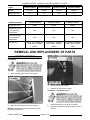
REMOVAL AND REPLACEMENT OF PARTS
COVERS & PANELS
Front Panel
1.
Remove lower panel screws from cabinet.
3.
Remove panel from cabinet.
4.
Reverse the procedure to install.
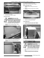
Condenser / Compressor Cover
2.
Remove upper panel screws from cabinet.
NOTE: Upper panel screws are accessed from the
back side of front panel.
F25393 (August 2010)
1.
Access condenser cover at top of cabinet.
2.
Remove all screws securing condenser cover to
cabinet.
Page 6 of 32
G SERIES FREEZER - REMOVAL AND REPLACEMENT OF PARTS
4.
Reverse the procedure to install.
NOTE: Replace adhesive seal as needed.
Harness Raceway Cover
3.
Lift cover from cabinet.
4.
Reverse the procedure to install.
1.
Access harness raceway cover at top of
cabinet.
2.
Remove screws securing cover to raceway
housing.
3.
Lift cover up from raceway housing.
4.
Reverse the procedure to install.
Evaporator Cover
Control Box Cover
1.
Access evaporator cover at top of cabinet.
2.
Remove bolts securing evaporator cover to
cabinet.
3.
Use of a screw driver to aid in prying up cover
to break adhesive seal then lift cover from
cabinet.
1.
Access control box cover at top of cabinet.
2.
Remove screws securing cover to cabinet.
3.
Lift cover up from control box.
4.
Reverse the procedure to install.
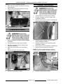
CABINET LAMP
1.
Open cabinet door to gain access to cabinet
light.
2.
Reach up and carefully squeeze lamp lens
inward to release lens from mounting tabs.
Page 7 of 32
F25393 (August 2010)
G SERIES FREEZER - REMOVAL AND REPLACEMENT OF PARTS
other mounting clip.
3.
Remove lens from cabinet.
4.
Turn lamp to remove from lamp socket.
5.
Reverse the procedure to install.
INTELA-TRAUL CONTROL
7.
Push Intela-Traul control out from front top
panel.
8.
Reverse the procedure to install.
Removal
1.
Remove front panel as outlined under COVERS
& PANELS.
2.
Access control at top of cabinet.
3.
Remove control box cover as outlined under
COVERS & PANELS.
NOTE: Use care not to damage lead wires.
4.
Loosen screws securing harness connector to
Intela-Traul Control.
5.
Disconnect harness connector from Intela-Traul
Control.
INTELA-TRAUL RELAY MODULE
Removal
6.
Compress in both sides of mounting clip, while
sliding clip off Intela-Traul control. Repeat for
F25393 (August 2010)
1.
Remove front panel as outlined under COVERS
& PANELS.
2.
Access Intela-Traul relay module at top of
cabinet.
3.
Remove control box cover as outlined under
COVERS & PANELS.
Page 8 of 32
G SERIES FREEZER - REMOVAL AND REPLACEMENT OF PARTS
NOTE: Use care not to damage lead wires.
4.
Disconnect all lead wire connectors from IntelaTraul relay box.
5.
Remove both nuts securing Intela-Traul relay
module to control box cover.
6.
CABINET AIR SENSOR
1.
Access cabinet air sensor at top of cabinet.
2.
Remove evaporator cover as outlined under
COVERS & PANELS.
3.
Remove screw securing sensor & mounting clip
to evaporator compartment.
Reverse the procedure to install.
COMPRESSOR RELAY
1.
Remove front panel as outlined under COVERS
& PANELS.
4.
Remove harness raceway cover as outlined
under COVERS & PANELS.
2.
Access compressor relay at top of cabinet.
5.
3.
Remove control box cover as outlined under
COVERS & PANELS.
Remove control box cover as outlined under
COVERS & PANELS.
6.
Route sensor out from evaporator compartment.
4.
Disconnect all lead wires from compressor
relay.
7.
Disconnect sensor lead wire connector.
5.
Remove nuts from compressor relay.
NOTE: The green insulation lead wire to green
indicator tape on connector for proper connection.
6.
Reverse the procedure to install.
8.
Page 9 of 32
Reverse the procedure to install.
F25393 (August 2010)
G SERIES FREEZER - REMOVAL AND REPLACEMENT OF PARTS
EVAPORATOR COIL SENSOR
THERMAL EXPANSION VALVE
1.
Access cabinet coil sensor at top of cabinet.
1.
2.
Remove evaporator cover as outlined under
COVERS & PANELS.
Access thermal expansion valve at top of
cabinet.
2.
3.
Pull sensor out from evaporator fins.
Remove evaporator cover as outlined under
COVERS & PANELS.
3.
Cut wire ties off from refrigerant line insulation.
4.
Remove pipe insulation from refrigerant line.
5.
Remove insulation from refrigerant line.
6.
Loosen bolts securing sensor from refrigerant
line.
7.
Pull sensor out from mounting bracket.
8.
Remove expansion valve from the liquid line at
inlet and outlet of valve.
9.
Install replacement expansion valve into inlet
and fasten sensor to suction line.
NOTE: Sensor location for replacement.
4.
Remove harness raceway cover as outlined
under COVERS & PANELS.
5.
Remove control box cover as outlined under
COVERS & PANELS.
6.
Route sensor out from evaporator compartment.
7.
Disconnect sensor lead wire connector.
NOTE: The blue insulation lead wire to blue indicator
tape on connector for proper connection.
8.
Reverse procedure to install.
10. Recharge unit and check for leaks.
11. Put system back into operation and check the
superheat as outlined under CHECK
REFRIGERANT CHARGE in SERVICE
PROCEDURES AND ADJUSTMENTS.
F25393 (August 2010)
Page 10 of 32
G SERIES FREEZER - REMOVAL AND REPLACEMENT OF PARTS
NOTE: Sensor must be insulated.
NOTE: It is recommended that the filter/drier be
changed when this part is replaced.
EVAPORATOR COIL / DEFROST
HEATER
1.
Access defrost heater at top of cabinet.
2.
Remove evaporator cover as outlined under
COVERS & PANELS.
3.
Remove harness raceway cover as outlined
under COVERS & PANELS.
4.
Disconnect heater lead wire connector.
7.
Remove defrost heater mounting clips from
evaporator coil to release defrost heater.
8.
Route heater lead wires out from evaporator
compartment.
9.
Reverse the procedure to install.
DOOR GASKET
5.
Remove adhesive tape over refrigeration lines.
To Remove:
1.
Open cabinet door to gain access to door
gasket.
2.
Start at one corner of the gasket and pull gasket
out from the gasket retaining channel.
A.
6.
Continue to pull gasket from door until
gasket is completely out of gasket retaining
channel.
Lift evaporator coil up and out from evaporator
compartment to expose bottom of evaporator
coil.
NOTE: Do Not kink refrigeration lines or damage
lead wires.
Page 11 of 32
F25393 (August 2010)
G SERIES FREEZER - REMOVAL AND REPLACEMENT OF PARTS
EVAPORATOR FAN
1.
Access evaporator fan lead wires at top of
cabinet.
2.
Remove evaporator cover as outlined under
COVERS & PANELS.
3.
Disconnect lead wires to evaporator fans.
NOTE: Mark lead wires for later installation.
To Install:
1.
Run a small bead of food grade silicone in
gasket retainer channel.
2.
Install gasket starting at corners pressing into
retainer gasket channel and work towards
center.
DOOR ASSEMBLY
1.
Remove screw from upper door hinge.
4.
Open cabinet door to gain access to evaporator
fan housing.
5.
Loosen screws securing evaporator air duct to
cabinet.
A.
Slide evaporator air duct away from right
side cabinet wall and allow duct to lower
into cabinet.
NOTE: Mounting holes in evaporator air duct are
keyhole slots.
2.
Lift door assembly upward off hinges and set
door assembly aside.
3.
Reverse the procedure to install.
NOTE: Install original hinge assemblies onto
replacement door.
6.
F25393 (August 2010)
Page 12 of 32
Remove screws securing evaporator fan
housing to evaporator compartment.
G SERIES FREEZER - REMOVAL AND REPLACEMENT OF PARTS
box.
NOTE: Mark wire location for installation.
7.
Allow evaporator fan housing to lower out of
cabinet.
8.
Reverse the procedure to install.
CONDENSING UNIT
COMPONENTS
5.
Remove insulation from refrigerant line.
6.
Disconnect suction and discharge lines from
compressor.
7.
Remove bolts securing compressor to cabinet.
8.
Install new compressor and connect wire leads
at compressor junction box.
9.
Install new filter drier.
Compressor
1.
Remove condenser / compressor cover as
outlined under COVERS & PANELS.
2.
Evacuate refrigeration system.
NOTE: The use of reclaiming equipment is
mandatory.
3.
Use of screwdriver to lift retaining brace upward
off junction box cover.
10. Evacuate refrigeration system.
11. Charge system and put unit into operation.
12. Check for proper operation.
Condenser Fan Assembly
4.
Disconnect lead wires from compressor junction
1.
Remove condenser / compressor cover as
outlined under COVERS & PANELS.
2.
Disconnect lead wires to condenser fan.
3.
Remove screws securing condenser fan
mounting bracket to cabinet.
Page 13 of 32
F25393 (August 2010)
G SERIES FREEZER - REMOVAL AND REPLACEMENT OF PARTS
5.
4.
Remove the screws securing mounting bracket
to condenser fan.
Reverse procedure to install coil, then proceed
to next step.
NOTE: It is recommended that the filter drier be
changed when this part is replaced.
6.
Evacuate refrigeration system.
NOTE: The use of reclaiming equipment is
mandatory.
7.
Charge system and put unit into operation.
Filter Drier
5.
1.
Remove condenser / compressor cover as
outlined under COVERS & PANELS.
2.
Remove filter drier from liquid lines.
3.
Install a new filter direr.
4.
Evacuate refrigeration system.
NOTE: The use of reclaiming equipment is
mandatory.
Reverse the procedure to install.
Condenser Coil
5.
Charge system and put unit into operation.
HOT GAS CONDENSATE PAN
1.
Evacuate refrigeration system.
NOTE: The use of reclaiming equipment is
mandatory.
2.
Remove condenser / compressor cover as
outlined under COVERS & PANELS.
3.
Disconnect inlet and outlet lines at the soldered
connections nearest the condenser coil.
4.
Remove screws securing coil to mounting plate.
F25393 (August 2010)
1.
Remove condenser / compressor cover as
outlined under COVERS & PANELS.
2.
Remove screw securing hot gas coil retaining
bracket to the cabinet.
NOTE: Do not damage the coil during removal.
Page 14 of 32
G SERIES FREEZER - SERVICE PROCEDURES AND ADJUSTMENTS
3.
Lift the retaining bracket up out from insert slot
in cabinet.
4.
Lift the hot gas coil out of condensate pan.
5.
Pull hot gas pan from cabinet.
6.
Reverse procedure to install.
SERVICE PROCEDURES AND ADJUSTMENTS
CHECK REFRIGERANT CHARGE
(SUPERHEAT, SUB COOLING &
SPLIT TEMPERATURES)
Introduction
Superheat is the heat that the refrigerant vapor
absorbs above the boiling point.
Helpful Hints
•
7 degrees F is a desirable superheat at coil
outlet, but superheat for the TXV's are set at the
factory.
Procedure
1.
Superheat Temperature
2.
Connect a temperature probe thermocouple to
the evaporator coil outlet (D).
A.
3.
Connect a temperature probe thermocouple to
the evaporator coil inlet (C).
A.
4.
Page 15 of 32
Install a piece of pipe insulation around the
thermocouple probe.
Install a piece of pipe insulation around the
thermocouple probe.
If applicable, install all evaporator box covers
over evaporator.
F25393 (August 2010)
G SERIES FREEZER - SERVICE PROCEDURES AND ADJUSTMENTS
5.
Let refrigerant system run. Temperature
readings should be taken after the cabinet is at
pull down temperature & just before the
compressor cycles off.
6.
Take readings of evaporator coil inlet (C) &
evaporator coil outlet (D) lines.
Example: [(condenser inlet (A) + condenser outlet
(B)) / 2] !ambient temp. = split temperature.
A.
6.
If split temperature reading is out of spec, call
Refrigeration Service Support.
7.
Remove thermocouples and install all covers &
panels.
Subtract temperature reading of evaporator
coil outlet temperature (D) to the
evaporator coil inlet temperature (C)
reading to obtain a superheat temperature.
B.
Example: evaporator outlet temp. (D) - evaporator
inlet temp. (C) = superheat temp.
To obtain a split temperature reading: add
condenser coil inlet (A) & condenser coil
outlet (B) readings divide by 2 and then
subtract ambient temperature reading.
CHECKING FOR LEAKS
NOTE: TXV superheat is set at the factory and is not
adjustable.
B.
7.
If superheat temperature reading is out of
spec, call Refrigeration Service Support.
Remove thermocouples and install all covers &
panels.
Sub Cooling & Split Temperatures
1.
Connect a temperature probe thermocouple to
the condenser coil inlet (A).
A.
2.
Install a piece of pipe insulation around the
thermocouple probe.
1.
Access the refrigeration system.
2.
Connect the low (blue) side of gauge manifold
to schrader valve.
3.
Connect refrigerant bottle to center of gauge
manifold and open valve on bottle.
4.
Open valve on low side of gauge manifold and
charge system with a small amount of
refrigerant (1 to 2 ounces).
5.
Close bottle valve and gauge valve.
6.
Disconnect refrigerant bottle and connect
nitrogen bottle.
7.
Set output valve on nitrogen bottle to 120 psi.
Connect a temperature probe thermocouple to
the condenser coil outlet (B).
8.
Open nitrogen bottle valve and gauge manifold
valve (low side) and allow pressure to equalize.
A.
9.
Shut off both valves and disconnect the nitrogen
bottle.
Install a piece of pipe insulation around the
thermocouple probe.
3.
If applicable, install all evaporator box covers
over evaporator.
4.
Let refrigerant system run for approximately 3 to
5 minutes before taking temperature readings.
A.
If any leaks are detected, repair the leak
and recheck.
5.
Take readings of condenser coil inlet (A) &
condenser coil outlet (B) lines.
B.
If no leaks are discovered, evacuate
system as outlined under EVACUATING
SYSTEM.
A.
10. Using a leak detector or a thick soapy solution,
check for leaks at all tubing connections.
To obtain a sub cooling temperature
reading: add condenser coil inlet (A) &
condenser coil outlet (B) readings divide by
2 and then subtract condenser coil outlet
(B) reading.
11. Charge system as outlined under CHARGING
SYSTEM.
Example: [(condenser inlet (A) + condenser outlet
temp. (B)) / 2] !condenser outlet (B) = sub cooling
temperature.
F25393 (August 2010)
Page 16 of 32
G SERIES FREEZER - SERVICE PROCEDURES AND ADJUSTMENTS
7.
EVACUATING SYSTEM
Introduction
Refrigeration reclaiming equipment is required.
Repeat steps 5 and 6 once.
8.
Pull vacuum to 500 microns.
9.
Charge system and check for proper operation.
CHARGING SYSTEM
The goal in system evacuation is to remove all the
non-condensables as possible. No evacuation
method will remove 100% of the moisture and air
from within the refrigeration circuit. Because of this,
guidelines and methods must be developed and
adhered to ensuring only harmless amounts of
contaminants remain in the system.
Guidelines
•
Use only a two stage vacuum pump (2 CFM or
greater) and electronic micron gauge integrated
into a refrigeration reclaiming system.
1.
Access the refrigeration system.
•
Evacuate from high to low sides of system.
2.
•
No chemical additives or alcohols are to be
used to Dry Up a system.
Be sure system is properly leak checked and
evacuated before charging as outlined under
LEAK CHECK and EVACUATING SYSTEM.
•
No Flushing with solvents or any type of Freon
alien to system. Blow down of system with DRY
NITROGEN prior to evacuation is acceptable
and many times desirable. See SYSTEM
CLEAN UP.
3.
Connect high side of gauge manifold to the
receiver valve. Make certain both valves are
closed on the gauge manifold.
•
Evacuate to 500 microns of mercury.
Procedure
NOTE: Charge the system through the high side to
prevent liquid refrigerant from reaching the
compressor.
4.
Connect refrigerant bottle to center connection
of gauge manifold.
5.
Turn the refrigerant bottle upside down.
6.
Open valves on bottle, gauge manifold and
receiver.
7.
Allow the proper amount of refrigerant to enter
the system, then shut the gauge and bottle
valves.
8.
Disconnect the hose from the receiver valve.
9.
Reconnect power to the unit and check for
proper operation and high pressure leaks.
10. Disconnect power to the unit and replace any
covers removed.
11. Reconnect power to the unit.
SYSTEM CLEAN UP
1.
Access the refrigeration system.
2.
Connect low (blue) side of gauge manifold to
schrader valve on compressor access line and
high (red) side of gauge manifold to schrader
valve on filter drier line.
3.
Connect center line of gauge manifold to
vacuum pump.
4.
Turn vacuum pump on and open both sides of
gauge manifold.
5.
Pull a vacuum to 500 microns.
6.
Break the vacuum with 3 psig of operating
refrigerant. On remote systems DRY
NITROGEN may be preferred.
Introduction
When a compressor burn-out is encountered, the
service person must make the determination as to
the degree of system contamination.
Normally a compressor burn-out will fit in one of
three categories:
Page 17 of 32
F25393 (August 2010)
G SERIES FREEZER - SERVICE PROCEDURES AND ADJUSTMENTS
•
Contained - compressor oil not acidic, no oil
discoloration.
•
Contaminated compressor - oil acidic,
discoloration of oil, contamination limited to
compressor.
The control program software version can be
determined by:
•
Massive contamination - contaminated oil and /
or refrigerant pumped into system.
1.
Turn power on to the Intela-Traul control.
2.
While control powers up the control display will
show the software version for a second (C32
and above).
SOFTWARE VERSION
Contained
1.
Replacement of liquid line drier.
2.
Install suction line filter drier.
3.
Replacement of compressor.
4.
Evacuation (to 500 microns).
5.
Charge by weight.
CONTROL CALIBRATION
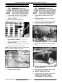
Certain components in this system are
subject to damage by electrostatic discharge during
field repairs. A field service grounding kit is available
to prevent damage. The field service grounding kit
must be used anytime the control board is handled.
Contaminated Compressor
The Contaminated Compressor requires the same
procedure as the Contained Burn-Out. Plus, the
system must be flushed after the compressor and
drier have been removed.
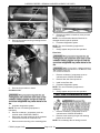
1.
Verify that the cabinet air sensor is functioning
properly as outlined under CABINET AIR, &
CABINET COIL, SENSOR TEST.
2.
Place a thermocouple of a temperature tester in
the center of right incoming air slot of the
cabinet.
Massive Contamination
A.
The replacement compressor MUST NOT be
installed until after system clean-up procedures have
been completed.
Route thermocouple through hinge side of
door to the outside of the cabinet and close
the door(s).
Remove the burned-out compressor as outlined
under COMPRESSOR in REMOVAL AND
REPLACEMENT OF PARTS.
3.
Set the control temperature to 0EF.
4.
Allow the cabinet temperature to stabilize
(minimum 3 cycles).
2.
Remove any of the in-line refrigerant controls.
5.
3.
Flush high and low sides of system until acidic
oil has been removed from the remaining
components of the system.
Note temperature reading on temperature tester
and control display at the exact time the
refrigeration system turns off.
6.
4.
Reassemble refrigeration system.
If the temperature difference between the two
readings is greater than ±2EF or ±1EC, adjust if:
5.
Evacuate refrigeration system as outlined under
EVACUATING SYSTEM.
A.
If temperature test shows a temperature
higher than control, increase.
6.
Charge system as outlined under CHARGING
SYSTEM.
B.
If temperature test shows a temperature
lower than control, decrease.
7.
Reconnect power and check for proper
operation.
C.
8.
Disconnect power and install any panels
removed.
If temperature difference is greater than
the range of the control, replace controller
(range ±50EF. or ±10EC.).
9.
Reconnect power. After 24 hours of operation
check system for acid and proper operation.
1.
7.
Check for proper operation.
8.
Remove temperature tester thermocouple from
the cabinet.
10. Once the system is determined clean, remove
the suction line drier.
F25393 (August 2010)
Page 18 of 32
G SERIES FREEZER - SERVICE PROCEDURES AND ADJUSTMENTS
CONTROL PARAMETERS
NOTE: Not all control parameters can be adjusted at the customer level of access. To adjust parameters not at the
customer level it will be necessary to access the engineering level.
NOTE: If 30 seconds elapse between keypad presses, the controller will revert to a cabinet temperature display
(normal operation). If the wrong security code is entered, the controller will revert to a cabinet temperature display
(normal operation). To save settings & exit customer access mode, press the alarm cancel keypad or not pressing
any keypads for 30 seconds.
To Access Customer Level
1. Use security code 0A1 by:
2. Pressing the Set keypad until CUS is displayed.
3. Press the Set keypad until left zero is flashing with three zeros displayed.
4. Press the Set keypad until center zero is flashing with three zeros displayed.
5. Press the Down Arrow until A is shown in center display.
6. Press Set keypad until right zero is flashing with 0A0 displayed.
7. Press the Up Arrow until 1 is flashing in right display.
8. Press the Set keypad. Display should read SP (Thermostat Set Point) indicating controller is in Customer
Access Mode.
To Access Engineering Level
1. Press the Set keypad until CUS is displayed.
2. Press the DOWN ARROW keypad until ENG is displayed.
3. Press the Set keypad until 000 is displayed with the left digit flashing.
4. Press the DOWN ARROW keypad until left digit displays 9.
5. Press the Set keypad until the center digit flashes.
6. Press the DOWN ARROW keypad until center digit displays 9.
7. Press the Set keypad until the right digit flashes.
8. Press the DOWN ARROW keypad until the right digit displays E.
9. Press SET keypad then the DOWN ARROW keypad until FOC is displayed.
NOTE: Hex File GF1 (Standard) and GF3 (-10 EF Freezer).
10. Use the DOWN ARROW keypad to scroll through control parameters.
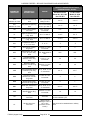
DEFAULT PARAMETER SETTINGS
(FREEZER MODEL SERIES)
PARAMETER
DISPLAYED
DESCRIPTION /
ACCESS LEVEL
RANGE
Standard Freezer
Model G1, G2, & G3
Hex File GF1
-10 EF Freezer
Model G1 & G2
Hex File GF3
SPH
software ver. C28
Temperature set point
high / Cus. level
SHH to SHL
0 EF
-5.0EF
SPL
software ver. C28
Temperature set point
low / Cuc. level
SLH to SLL
-4.0EF
-10.0EF
SP
software ver. C32
& above
Set point cut out
temperature
-3.0 EF
-10.0 EF
SPD
software ver. C32
& above
Set point differential
SP TO SPD
2.0 EF
4.0 EF
SHL
software ver. C28
Set point high-low /
Eng. level
-40EF. up to current
setting for SHH
-2.0 EF
-8.0 EF
SHH
software ver. C28
Set point high-high /
Eng. level
From current setting
for SHL up to
266EF.
2.0 EF
-5.0 EF
Page 19 of 32
F25393 (August 2010)
G SERIES FREEZER - SERVICE PROCEDURES AND ADJUSTMENTS
DEFAULT PARAMETER SETTINGS
(FREEZER MODEL SERIES)
PARAMETER
DISPLAYED
DESCRIPTION /
ACCESS LEVEL
RANGE
Standard Freezer
Model G1, G2, & G3
Hex File GF1
-10 EF Freezer
Model G1 & G2
Hex File GF3
SLL
software ver. C28
Set point low-low/ Eng.
level
-40EF. up to current
setting for SLH
-6.0 EF
-13.0 EF
SLH
software ver. C28
Set point low-high/ Eng.
level
from current setting
for SLL up to 266 EF
-2.5 EF
-10 EF
RO
Room ambient offset /
Cuc. level
±3EF. in 1/2EF.
increments
0 EF
0 EF
HI
Upper temperature limit
/ Eng. level
-40 EF. to 266EF.
10.0EF
5.0 EF
LO
Lower temperature limit
/ Eng. level
-40 EF. to 266EF.
-15.0 EF
-15.0 EF
SCL
Temperature scale EF
or EC / Cuc. level
EF. or EC.
EF
EF
AC
Anti-cycling- minute /
Eng. level
1-10 min. in 1 min.
increments
3
3
DEF
Defrost type- ele., gas,
none, off cycle / Eng.
level
ELE, GAS, NONE or
OFF
ELE
ELE
IBD
Intervals between
defrosts- hours / Eng.
level
1-9 hrs. in 1 hr.
increments
4.0
4.0
DDC
Maximum defrost
duration- minute / Eng.
level
0-30 min. in 5 min.
increments
30
30
CDE
Coil temperature at end
of defrost cycle / Eng.
level
40 EF. to 80 EF. in 5
EF. increments
45 EF
45 EF
DDE
Drip time at end of
defrost cycle- minute /
Eng. level
1-5 min. in 1 min.
increments
4
4
BDD
Blower delay at drip
time-minute / Eng. level
0-5 min. in 1 min.
increments
6
7
BSD
BSD after defrost end /
Eng. level
30 EF. to 40 EF. in 1
EF. increments
20.0 EF
10.0 EF
ODD
Display hold after
defrost-minute / Eng.
level
0-30 min. in 5 min.
increments
10
10
SD
Start-Stop defrost /
Cus. level
YES / NO
CL
F25393 (August 2010)
Set the clock time /
Cus. level
00:00 to 23:59
Setting for 12hr. or
24 hr. time
(H=hours, N=min.,
S=sec.)
Page 20 of 32
Start a new defrost cycle at any time or stops
a current defrost cycle.
Set the clock for standard time or military
time.
G SERIES FREEZER - SERVICE PROCEDURES AND ADJUSTMENTS
DEFAULT PARAMETER SETTINGS
(FREEZER MODEL SERIES)
PARAMETER
DISPLAYED
DESCRIPTION /
ACCESS LEVEL
RANGE
DAY
Set the clock date /
Cus. level
(Y=year, N=month,
E=day # in week
example: Sun=1
Sat=7)
DS
Daylight Savings / Cus.
level
ON / OFF
ON
ON
DL1
Defrost lockout 1 / Cus.
level
2:00 to 8:00 in. 30
min. increments &
OFF
OFF
OFF
DL3
Defrost lockout 3 / Cus.
level
14:00 to 20:00 in. 30
min. increments &
OFF
OFF
OFF
DL4
Defrost lockout 4 / Cus.
level
2:00 to 20:00 in. 30
min. increments &
OFF
OFF
OFF
DCF
software ver. C28
Dewpoint correction
factor / Cus. level
0 to 100
100
100
CON
Compressor default On
time / Eng. level
5-30 min. in 1 min.
increments
20
20
COF
Compressor Off time /
Eng. level
5-30 min. in 1 min.
increments
5
5
EL
Evaporator coil
temperature / Cus.
level
n/a
Displays evaporator coil temperature in real
time every time an arrow keypad is pressed.
CB
Cabinet air temperature
/ Cus. level
n/a
Displays cabinet air temperature in real time
every time an arrow keypad is pressed.
PLn
software ver. C28
Display line voltage /
Eng. level
n/a
Displays power line voltage in real time every
time an arrow keypad is pressed.
RCO
Cycle compressor relay
/ Eng. level
n/a
Turns On/Off the compressor relay for 10
seconds or until an arrow keypad is pressed.
RdF
Cycle defrost relay /
Eng. level
n/a
Turns On/Off the defrost relay for 10
seconds or until an arrow keypad is pressed.
RFA
Cycle fan relay / Eng.
level
n/a
Turns On/Off the blower relay for 10 seconds
or until an arrow keypad is pressed.
RDH
Cycle door heater relay
/ Eng. level
n/a
Turns On/Off the door heater for 10 seconds
or until an arrow keypad is pressed.
CEP
Clear EPROM & load
defaults / Eng. level
n/a
Clear all control memories and reloads the
factory default parameters.
Ref
Software version,
revision, step / n/a level
n/a
Firmware revision in the format X9.9
(X=version, 9=major revision, .9= minor
revision).
Sn
Cabinet serial number /
Cus. level
n/a
11.
-10 EF Freezer
Model G1 & G2
Hex File GF3
Standard Freezer
Model G1, G2, & G3
Hex File GF1
Set the year, month, day of the month and
day of the week.
n/a
To exit, press the alarm cancel keypad or not pressing any keypads for 30 seconds.
Page 21 of 32
F25393 (August 2010)
G SERIES FREEZER - ELECTRICAL OPERATION
4.
EVAPORATOR COIL SENSOR
TEST
Verify multi meter reading to the temperature
conversion chart as follows.
Temperature
EF
Ohm Reading
K Ohms
Temperature
EC
-5.0
99.9
-20.5
1.
Access the customer level by pressing the Set
keypad until CUS is displayed.
2.
Press the Set keypad until left zero is flashing
with three zeros displayed.
0
85.2
-17.7
3.
Press the Set keypad until center zero is
flashing with three zeros displayed.
5.0
72.9
-15.0
4.
Press the Down Arrow until A is shown in center
display.
10.0
62.4
-12.2
5.
Press Set keypad until right zero is flashing with
0A0 displayed.
15.0
53.7
-9.4
6.
Press the Up Arrow until 1 is flashing in right
display.
20.0
46.2
-6.7
25.0
39.9
-3.9
7.
Press Up Arrow until EL is displayed then press
Set keypad.
30.0
34.6
-1.1
A.
If display shows -40 check for loose wire
connections and retest.
32.0
32.7
0.0
B.
If display shows 266 OR higher replace the
evaporator coil sensor.
35.0
30.1
1.7
40.0
26.1
4.4
45.0
22.8
7.2
CABINET AIR SENSOR TEST
50.0
19.9
10.0
1.
Access the customer level by pressing the Set
keypad until CUS is displayed.
55.0
17.4
12.8
2.
Press the Set keypad until left zero is flashing
with three zeros displayed.
60.0
15.3
15.6
3.
Press the Set keypad until center zero is
flashing with three zeros displayed.
65.0
13.5
18.3
70.0
11.9
21.1
4.
Press the Down Arrow until A is shown in center
display.
5.
Press Set keypad until right zero is flashing with
0A0 displayed.
6.
Press the Up Arrow until 1 is flashing in right
display.
7.
Press Up Arrow until AA is displayed then press
Set keypad.
NOTE: Erratic display readings indicate an open or
short in the control.
A.
If display shows 111 check for loose wire
connections and retest.
B.
If display shows 32.0 correct inadequate
air flow through the condenser, replace the
cabinet air sensor, or condenser fan
assembly.
NOTE: Erratic display readings indicate an open or
short in the control.
CABINET AIR, CABINET COIL,
& SENSOR RESISTANCE TEST
5.
If multi meter reading indicates an open or is
outside the ohm range ±10%, replace the
sensor.
COMPRESSOR RELAY TEST
1.
Turn supply power Off.
2.
Gain access to the compressor relay.
3.
Disconnect N.O. & COM lead wires from relay.
4.
Set the multi meter to ohm scale and connect
leads to relay N.O. & COM terminals .
5.
Verify the multi meter reading indicates an open
circuit. If not, replaced the relay .
DOOR SWITCH TEST
1.
Turn supply power Off.
2.
Open the cabinet doors.
3.
Gain access to the door switch.
1.
Gain access to the sensor.
4.
Disconnect lead wires from switch.
2.
Disconnect sensor lead wires from connector.
5.
3.
Set the multi meter to ohm scale and connect
leads to sensor lead wires.
Set the multi meter to ohm scale and connect
leads to switch terminals .
6.
Verify the multi meter reading indicates an open
circuit. If not, replaced the switch.
F25393 (August 2010)
Page 22 of 32
G SERIES FREEZER - ELECTRICAL OPERATION
ELECTRICAL OPERATION
COMPONENT FUNCTION
Intela-Traul Control . . . . .
Performs the following functions:
A. Displays all data for the current software revision & mode of operation.
B. Cycles refrigeration system to maintain cabinet temperatures.
C. Cycles defrost relay to defrost evaporator coil.
D. Monitors power losses as well as component malfunctions.
E. Monitors door position.
Compressor . . . . . . . . . . . . . . Pumps refrigerant through refrigeration system lines and components.
Start Capacitor . . . . . . . . . . . . Wired in series with the start windings to help start compressor motor.
Run Capacitor . . . . . . . . . . . . . Continually in circuit to help compressor motor during operation.
Compressor Relay . . . . . . . . . Senses current of run winding of compressor motor. Normally open contacts
close when the run winding draws a high amperage at start and brings the start
capacitor and start windings into the circuit. As the motor reaches operating
speed (less amperage through run winding), the normally open contacts open
and removes the start capacitor and start windings from the circuit.
Evaporator Fan . . . . . . . . . . . Draws air from the cabinet and moves the air through the evaporator coil back
into cabinet.
Condenser Fan
. . . . . . . . . . . Draws air across condenser coil to aid in removing heat from the refrigerant and
move air across compressor to aid in cooling the compressor.
Defrost Heater . . . . . . . . . . . . . Defrosts evaporator coil and prevents water droplets from evaporator coil to
freeze before they can drain to the condensate pan. Operates only during defrost
cycle.
Cabinet Air Sensor . . . . . . . . Monitors air temperature inside cabinet.
Cabinet Coil Sensor
. . . . . . . Monitors the evaporator coil while the cabinet is powered.
...........
Door Switch . . . . . . . . . . . . . . Monitors door for open or closed position. Evaporator fans stop when door is
open.
Solenoid Valve . . . . . . . . . . . . Normally closed when energized, allows refrigerant to flow from receiver to
evaporator coil.
Door Perimeter Heater . . . . . . Prevents condensate from forming on door frame.
Intela-Traul Relay Module . . . Controls power to the following components:
A. Evaporator fan(s).
B. Door heater.
C. Defrost heater.
D. Compressor relay.
E. Solenoid valve.
Main Switch . . . . . . . . . . . . . . . Controls power to intela-traul relay box, compressor relay, door switch, &
auxiliary components. Removes power from listed components.
Heated Glass Doors . . . . . . . . Auxiliary component, prevents condensate from forming on glass door.
Condensate Evaporator . . . . . Auxiliary component, when energized dissipates condensate in the evaporator
pan.
Page 23 of 32
F25393 (August 2010)
G SERIES FREEZER - ELECTRICAL OPERATION
SEQUENCE OF OPERATION
Refrigeration System
1.
The control must be powered on.
2.
The control monitors cabinet air temperature and senses a need for cooling.
3.
The compressor motor is energized and refrigerant is pumped through the system.
4.
The TXV monitors the evaporator superheat and meters the amount of refrigerant entering the evaporator.
5.
The control senses the cabinet air temperature requirements have been met.
6.
Compressor motor de-energized by the compressor relay.
7.
System is cycled by control.
Freezer Mode
1.
Main switch closed.
A. Relay module energized.
B. Control energized.
C. Compressor relay.
D. Condenser fan(s) energized.
E. Compressor motor energized.
2.
Control displays software revision & then cabinet temperature.
3.
After 2-1/2 minutes evaporator fan(s) energized.
4.
The refrigeration system will cycle on the air temperature of the cabinet.
A. On at the high set point (SP + D) temperature.
B. Off at the low set point (SP) temperature.
NOTE: Set points are selected in the parameter menu.
NOTE: If the cabinet door is opened during operation, the evaporator fan(s) will shut Off.
5.
Evaporator fan(s) cycled on time and or temperature.
6.
Unit is cycled by control.
Defrost Mode
1.
The defrost mode can be entered manually or run automatically.
2.
When control initiates a defrost cycle, the control snowflake is illuminated.
A. Defrost heater energized.
B. Compressor motor de-energized.
C. Evaporator fan(s) de-energized.
3.
Defrost cycle operates until the EL temperature setting is reached or the maximum DDC time setting has
elapsed.
4.
Defrost mode cycled by control.
F25393 (August 2010)
Page 24 of 32
G SERIES FREEZER - ELECTRICAL OPERATION
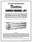
COMPONENT LOCATION
Page 25 of 32
F25393 (August 2010)
G SERIES FREEZER - ELECTRICAL OPERATION
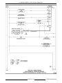
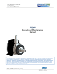
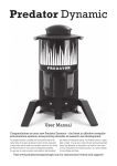
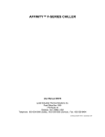
WIRING DIAGRAMS
115V/60HZ/1PH
F25393 (August 2010)
Page 26 of 32
G SERIES FREEZER - ELECTRICAL OPERATION
220V/50-60HZ/1PH
Page 27 of 32
F25393 (August 2010)
G SERIES FREEZER - TROUBLESHOOTING
TROUBLESHOOTING
SYMPTOM
Nothing runs, blank control.
Compressor will not run, no current draw.
Compressor will not run, current draw and trips
breaker.
Defrost time too long.
Compressor short cycles.
Compressor run time lengthy.
Continuous compressor operation.
Low suction pressure.
High head pressure.
F25393 (August 2010)
3.
4.
5.
6.
7.
8.
9.
POSSIBLE CAUSES
Main circuit breaker open.
Main on/off switch off.
Power cord unplugged.
Cabinet temperature satisfied.
Door open or malfunction door switch, with display on
control.
Incorrect wiring.
Cabinet air sensor malfunctioned.
Start component malfunctioned.
Compressor motor windings open.
Control malfunctioned.
Compressor relay malfunctioned.
Relay module malfunctioned.
1.
2.
3.
1.
2.
3.
4.
1.
2.
3.
4.
5.
6.
7.
1.
2.
3.
4.
5.
6.
7.
8.
9.
10.
11.
12.
1.
2.
3.
4.
1.
2.
3.
1.
2.
3.
4.
5.
Start component malfunctioned.
Compressor motor windings shorted.
Locked rotor.
Evaporator coil sensor malfunctioned.
Incorrect wiring.
Control malfunctioned.
Defrost heater malfunctioned.
Improper air flow over evaporator coil.
Expansion valve malfunctioned.
Low ambient conditions.
Evaporator fan(s) malfunctioned.
Cabinet air sensor malfunctioned.
Evaporator coil sensor malfunctioned.
Control malfunctioned.
Partial loss of refrigerant.
High ambient conditions.
Improper air flow over condenser coil.
Excessive product load.
Excessive door openings.
Door gasket(s) need replaced.
Condenser fan(s) malfunctioned.
Cabinet air sensor malfunctioned.
Cabinet coil sensor malfunctioned.
Contaminates in refrigeration system.
Control malfunctioned.
Relay module malfunctioned.
Loss of refrigerant.
Excessive door openings.
Cabinet air sensor malfunction.
Control malfunctioned.
Restriction in refrigeration system.
Loss of refrigerant.
Expansion valve blocked.
Improper air flow across condenser.
Extreme ambient conditions.
Overcharge of refrigerant.
Air in refrigerant system.
Condenser fan(s) malfunctioned.
1.
2.
3.
1.
2.
Page 28 of 32
G SERIES FREEZER - TROUBLESHOOTING
SYMPTOM
Iced Evaporator coil.
Will not defrost.
Control display blank.
1.
2.
3.
4.
5.
6.
7.
8.
1.
2.
3.
4.
5.
1.
2.
3.
4.
POSSIBLE CAUSES
Evaporator fan(s) malfunctioned.
Verify defrost control parameter settings.
Evaporator coil sensor malfunctioned.
Compressor relay malfunctioned.
Control relay module.
Cabinet air sensor malfunctioned.
Control malfunctioned.
Refrigerant system malfunctioned.
Defrost heater(s) malfunction.
Incorrect wiring.
Compressor relay malfunctioned.
Evaporator coil sensor malfunctioned.
Control malfunctioned.
Main power supply.
Relay module malfunctioned.
On/off switch malfunctioned.
Control malfunctioned.
Page 29 of 32
F25393 (August 2010)
G SERIES FREEZER - TROUBLESHOOTING
-NOTES-
F25393 (August 2010)
Page 30 of 32
G SERIES FREEZER - TROUBLESHOOTING
-NOTES-
Page 31 of 32
F25393 (August 2010)
G SERIES FREEZER - TROUBLESHOOTING
-NOTES-
F25393 (August 2010)
Printed in U.S.A.