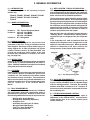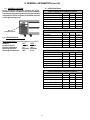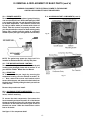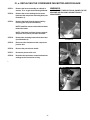
1
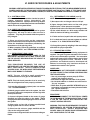
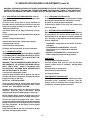
Traulsen Refrigeration
SERVICE MANUAL #07
Instructions For The Troubleshooting
And Repair Of All Traulsen TE-Series
Refrigerated Equipment Stand Models
Traulsen’s equipment stands are solely intended for use with cooking equipment.
-NOTICEThis Manual is prepared for the use of trained Authorized Traulsen Service Agents and should not be used
by those not properly qualified. This manual is not intended to be all encompassing, but is written to
supplement the formal training, on-the-job experience and other product knowledge acquired by Authorized Traulsen Service Agents. Before proceeding with any work, you should read, in its entirety, the repair
procedure you wish to perform to determine if you have the necessary tools, instruments and skills required
to perform the procedure. Procedures for which you do not have the necessary tools, instruments and
skills should be performed only by a trained Authorized Traulsen Service Agent.
Reproduction or other use of this Manual, without the express written consent of Traulsen, is prohibited.
FORM NUMBER TR35896 - REVISED. 06/15
TABLE OF CONTENTS
I. THE SERIAL TAG
1
IV. REPLACING THE... (cont’d)
f.
Compressor
10
II. GENERAL INFORMATION
a.
b.
c.
d.
e.
f.
g.
h.
i.
j.
k.
l.
Introduction
Model Designations
Wiring Diagrams
Installation - See Owner’s Manual
Cleaning
Tools
Refrigeration System Theory Of Operation
Air Flow Requirements
The Microprocessor Control
Control Locations
Specifications
Operating Data Chart
2
2
2
2
2
2
2
2
2
3
3
3
V. WIRING DIAGRAMS
a.
115V Refrigerator Models
11
VI. SERVICE PROCEDURES & ADJUSTMENTS
a.
b.
c.
d.
e.
f.
g.
System Access
Sweat On Piercing Valves
Refrigerant Leak Check
Evacuating System
Charging System
System Clean-Up
Heater Test/Drawer Perimeter Heater
12
12
12
13
13
14
14
VII. ELECTRICAL OPERATION
III. REMOVAL & REPLACEMENT OF PARTS
a.
b.
c.
d.
e.
f.
g.
h.
Louver Assembly
Evaporator Housing Cover
Removing The Drawer
Removing The Drawer Frame (slides)
Drawer Gaskets
Microprocessor Control
Condensate Drain Pan
Accessing Start Components
4
4
4
4
5
5
5
5
a.
b.
c.
d.
Sequence Of Operation/Normal Operation
Sequence Of Operation/Defrost Mode
Component Function
Installation of Sensors
14
14
15
15
VIII. REPLACEMENT PARTS LISTING
16
IX. TROUBLESHOOTING
17
IV. REPLACING THE...
a.
b.
c.
d.
Condenser Fan Motor and/or Blade
Condenser Coil
Evaporator Fan
Evaporator Coil
6
7
8
9
I. THE SERIAL TAG
The serial tag is a permanently affixed sticker on
which is recorded vital electrical and refrigeration data
about your Traulsen product, as well as the model
and serial number. This tag is located on the upper
right interior wall of all TE-Series models.
FORT WORTH, TX.
SERIAL
VOLTS
MODEL
Hz
PH
TOTAL CURRENT
AMPS
MINIMUM CIRCUIT
AMPS
MAXIMUM OVERCURRENT PROTECTION
LIGHTS
WATTS
HEATERS
AMPS
AMPS
REFRIGERANT
DESIGN PRESSURE
TYPE
HIGH
OZ
LOW
REFRIGERANT
DESIGN PRESSURE
TYPE
HIGH
OZ
LOW
READING THE SERIAL TAG
370-60294-00 REV (A)
-1-
• Serial = The permanent ID# of your Traulsen
• Model = The model # of your Traulsen
• Volts = Voltage
• Hz = Cycle
• PH = Phase
• Total Current = Maximum amp draw
• Minimum Circuit = Minimum circuit required
• Lights = Light wattage
• Heaters = Heater amperage
• Refrigerant = Refrigerant type used
• Design Pressure = High & low side operating
pressures and refrigerant charge
• Agency Labels = Designates agency listings
II. GENERAL INFORMATION
II. a - INTRODUCTION:
This manual applies to the following Traulsen
models only:
II. g - REF’N SYSTEM - THEORY OF OPERATION:
The refrigeration system is the mechanism whereby
heat is transferred from the cabinet to the outside air.
It works under the principle that the heat moves from
hot to cold as it tries to establish equilibrium.
TE036HT, TE048HT, TE060HT, TE065HT, TE072HT
TE084HT, TE096HT, TE110HT, TE125HT &
TE139HT
The microprocessor control signals a need for heat to
be removed from the cabinet. The compressor begins
by compressing the refrigerant gas as it is discharged.
The high pressure refrigerant now circulates through
the condenser, removing heat from the refrigerant and
condensing it into a liquid. From there the refrigerant
flows to the filter drier which removes all traces of
moisture and particles from the system.
II. b - MODEL DESIGNATIONS:
TE060HT
Position 1:
Position 2:
Position 3:
TE = Traulsen Equipment Stand
036 = 36” Long Model
048 = 48” Long Model
060 = 60” Long Model
HT = Refrigerator
After the filter drier, the refrigerant passes through a
“metering device.” Traulsen uses a capillary tube to
regulate the flow of refrigerant into the evaporator
coils.
In the evaporator coil, heat is transferred from the
cabinet to the refrigerant, which changes from a cold
liquid to a warm low pressure gas. When the desired
cabinet air temperature has been reached, the
microprocessor control shuts off the compressor.
II. c - WIRING DIAGRAM:
Refer to the wiring diagram for any service work
performed on this unit. A copy is located on the unit
when shipped. Should you require another copy, or a
wiring diagram for an older production unit, please
contact Traulsen Service at (800) 825-8220, and
provide the model and serial number of the unit
involved (this information is located on the serial
tag, see page one).
II. d - INSTALLATION:
Generally TE-Series refrigeration products are installed
by the dealer, or others contracted by the dealer or
owner. Detailed installation instructions are included
along with each unit when shipped.
II. e - CLEANING:
Detailed cleaning instructions are included with each
unit, however special care MUST be given to the
condenser coil. The condenser coil must be cleaned
at a minimum of every six months. This can be done
with a vacuum cleaner using a brush attachment, or a
stiff brush or wisk broom. For more information please
refer to “Section V.a” of the TE-Series Owner’s
Manual.
Fig. 1 - The Refrigeration System
II. h - AIR FLOW REQUIREMENTS:
To assure optimum performance, the condensing unit
of your Traulsen unit MUST have an adequate supply
of air for cooling purposes. Therefore, the operating
location must allow a minimum of 12” clearance in
front of the louvers to allow for unrestricted air flow to
the condensing unit.
II. f - TOOL REQUIREMENTS:
For most jobs a standard set of hand tools, a VOM and
AC current tester, along with a temperature tester or
thermometer are adequate. However in some cases
the following additional tools may be required as well:
•
•
•
•
•
•
•
II. i - THE MICROPROCESSOR CONTROL:
For detailed information on replacement, repair or
adjustment of the INTELA-TRAUL® microprocessor
control please refer to it’s service manual (form
number TR35705).
Refrigeration Guage Manifold
Refrigeration Reclaiming Equipment
Acetylene Torch
Anti-Static Grounding Kit (TL 84919)
Nitrogen Bottle With Gauges
Thin 5/16” Open End Wrench
Refrigerant Reclaim Unit
-2-
II. GENERAL INFORMATION (cont’d)
II. j - CONTROL LOCATION:
On all TE-Series refrigerator models, the microprocessor control is located on the louver assembly.
The louvers/refrigeration system are mounted standard
on the left side, but as an option are available mounted
on the right (see figure 2).
II. l - SPECIFICATIONS:
TE-Series Refrigerated Equipment Stands
TE036
TE048
TE060
Horsepower
1/3 HP
1/3 HP
1/3 HP
Condensing Unit - BTU/HR
2440
2440
2440
Condensing Unit Amp Draw
4.5
4.5
4.9
Fan, Lights, Etc. Amp Draw
0.6
0.6
1.1
R-404A
R-404A
R-404A
14.0
14.5
16.0
Refrigerant
Refrigerant Charge (oz.)
Fig. 2
Control Location
TE-Series Refrigerated Equipment Stands
TE065
II. k - OPERATING DATA CHART:
Refrigerated Models (cabinet temperature set at 38°F)
Ambient
Suction Pressure
Suction Temperature
Discharge Pressure
Discharge Temperature
70°F
35 PSIG
3°F
200 PSIG
88°F
100°F
50 PSIG
16°F
295 PSIG
115°F
TE072
TE084
Horsepower
1/3 HP
1/3 HP
1/3 HP
Condensing Unit - BTU/HR
2440
2440
2440
Condensing Unit Amp Draw
4.9
4.9
4.9
Fan, Lights, Etc. Amp Draw
1.1
1.1
1.1
R-404A
R-404A
R-404A
16.5
16.5
17.0
Refrigerant
Refrigerant Charge (oz.)
TE-Series Refrigerated Equipment Stands
Horsepower
TE096
TE110
TE125
1/2 HP
1/2 HP
1/2 HP
Condensing Unit - BTU/HR
4090
4090
4090
Condensing Unit Amp Draw
9.6
9.6
9.6
Fan, Lights, Etc. Amp Draw
1.5
1.5
1.5
R-404A
R-404A
R-404A
20.0
20.0
20.0
Refrigerant
Refrigerant Charge (oz.)
TE-Series Refrigerated Equipment Stands
TE139
Horsepower
1/2 HP
Condensing Unit - BTU/HR
4090
Condensing Unit Amp Draw
9.6
Fan, Lights, Etc. Amp Draw
1.9
Refrigerant
Refrigerant Charge (oz.)
-3-
R-404A
21.0
III. REMOVAL & REPLACEMENT OF BASIC PARTS
WARNING: DISCONNECT THE ELECTRICAL POWER TO THE MACHINE
AND FOLLOW LOCKOUT/TAGOUT PROCEDURES.
III. b - EVAPORATOR HOUSING COVER:
Remove the back cover by removing the four screws
which secure this to the cabinet (see figure 6).
III. a - LOUVER ASSEMBLY/SYSTEM ACCESS:
To remove the louver assembly first place your hands
under the louver panel and lift this up off the bracket
and then away from the cabinet face (see figure 3).
Fig. 6
Reverse the procedure when done to reinstall.
III. c - REMOVING THE DRAWERS:
Remove the drawer(s) from the drawer frame by lifting
up on the drawer, and then pulling out.
Fig. 3
To gain full access to the refrigeration system from
the side, remove the cover by removing the bottom
screws (see figures 4 & 5).
III. d - REMOVING THE DRAWER FRAME:
Once the drawer(s) have been removed, the drawer
frame module can also be removed by loosening the
front and back clamping knobs (2 of each), located on
the cross-rail and liner locks (see figures 7 & 8). Slide
the front cross-rail locks towards the center of the
drawer frame module and allow the liner locks to drop
down from the top of the liner.Pull the drawer frame
module forward, tip forward and pull out. The entire
frame assembly is now free to slide out of the cabinet.
Fig. 4
Screw
Locations
Fig. 7
Fig. 5
Side System
Access
When finished, lower the louver assembly into
position and replace the side panel. Secure these in
place using the previously removed screws.
Fig. 8
-4-
III. REMOVAL & REPLACEMENT OF BASIC PARTS (cont’d)
WARNING: DISCONNECT THE ELECTRICAL POWER TO THE MACHINE
AND FOLLOW LOCKOUT/TAGOUT PROCEDURES.
III. e - DRAWER GASKETS:
To remove the gasket to be replaced, grasp it firmly by
one corner and pull it out. Before attempting to install
a new gasket, both the unit and the gasket itself must
be at room temperature. Insert the four corners first
by using a rubber mallet (or hammer with a block of
wood). After the corners are properly inserted, work
your way towards the center from both ends by gently
hitting with a mallet until the gasket is completely
seated in place (see figure 9 for gasket cross section).
III. h - ACCESSING START COMPONENTS (cont’d):
Fig. 10
Fig. 9
NOTE: The gasket may appear too large, but if it is
installed as indicated above it will slip into place.
III. f - THE MICROPROCESSOR CONTROL:
To remove the microprocessor controller from the unit
in which it was installed, please refer to section “V” of
your INTELA-TRAUL® Master Service Manual.
III. g - DRAIN PAN:
To remove the drain pan, begin by removing the
evaporator housing cover as outlined in section “III.
c.” Next, remove the screws and brackets which
secure the drain pan, and remove the drain tube from
the drain pan. Finish by sliding the drain pan out from
under the coil.
Fig. 11
Reverse the procedure to install.
III. h - ACCESSING START COMPONENTS:
The start components are located behind the front
louver, inside a metal tray.
To access the start components, first remove the
louver assembly as shown in section III. a. Next loosen
the top set screw (see figure 10). and remove the molex
connection in the back of the box to gain access to
the back set screw. Slide the electrical box out the
font on its tracks.
See figure 11 for component detail.
-5-
IV. a - REPLACING THE CONDENSER FAN MOTOR AND/OR BLADE
STEP 1:
Remove the louver assembly as outlined in
section “III. a” to gain access through left side.
STEP 2:
Remove the screws holding the fan motor
bracket to the compressor mounting base (see
illustration 1).
STEP 3:
Remove the blade from the motor shaft by
removing the nut (see illustration 2).
WARNINGS:
1) DISCONNECT THE ELECTRICAL POWER TO THE
MACHINE AND FOLLOW LOCKOUT/TAGOUT
PROCEDURES.
NOTE: Install the concave side of the fan blade
toward the motor.
NOTE: If the blade is all that is being replaced,
stop here and reverse procedure to install.
STEP 4:
Remove the mounting bracket from the motor
(see illustration 3).
STEP 5:
Disconnect the lead wires at the compressor
junction box.
STEP 6:
Reverse the procedure to install.
STEP 7:
Reconnect power to the unit.
STEP 8:
Reset the microprocessor control defrost time
settings to the correct time of day.
Illustration 01
\
Illustration 02
Illustration 03
-6-
IV. b - REPLACING THE CONDENSER COIL
WARNINGS:
STEP 1:
1) DISCONNECT THE ELECTRICAL POWER TO THE
MACHINE AND FOLLOW LOCKOUT/TAGOUT
PROCEDURES.
Remove the louver assembly as outlined in
section “III. a”.
STEP 2:
Recover the refrigerant in the system
following the current EPA Guidelines for
refrigerant recovery.
2) THIS PROCEDURE REQUIRES THE USE OF REFRIGERANTS. BE CERTAIN THE WORK AREA IS WELL
VENTILATED. SAFETY GOGGLES AND GLOVES
SHALL BE WORN SINCE REFRIGERANTS MAY CAUSE
BURNS TO THE SKIN.
Illustration 01
NOTE: The use of reclaiming equipment is
required.
STEP 3:
Disconnect the input and output lines to the
condenser coil at the soldered joints closest
to the condenser.
STEP 4:
Remove the four (4) screws which secure the
condenser coil to the mounting brackets (see
illustration 1).
STEP 5:
Remove the condenser coil.
STEP 6:
Reverse the procedure to install the new
condenser coil.
STEP 7:
Install a new drier.
STEP 8:
Charge the refrigeration system as outlined
under “CHARGING SYSTEM” in “SERVICE
PROCEDUES AND ADJUSTMENTS.”
STEP 9:
Reconnect power to the unit.
STEP 10:
Reset the microprocessor control defrost time
settings to the correct time of the day.
-7-
IV. c - REPLACING THE EVAPORATOR FAN
STEP 1:
Begin by removing the back cover by first
removing the four screws which secure this to
the cabinet (see illustration 1).
All evaporators and fans are located along the
back wall of the cabinet and best accessed
from the rear (see illustration 2).
STEP 2:
Remove the holding rod and unhook the rod
from the other end. This evaporator fan can
then be lifted away from the assembly (see
illustration 3).
STEP 3:
Disconnect the wires from the assembly.
STEP 4:
Reverse the procedure to install the new
evaporator fan.
STEP 5:
Reconnect power to the unit.
STEP 6:
Reset the microprocessor control defrost time
settings to the correct time of the day.
WARNINGS:
1) DISCONNECT THE ELECTRICAL POWER TO THE
MACHINE AND FOLLOW LOCKOUT/TAGOUT
PROCEDURES.
Illustration 01
Illustration 02
Illustration 03
-8-
IV. d - REPLACING THE EVAPORATOR COIL
WARNINGS:
STEP 1:
1) DISCONNECT THE ELECTRICAL POWER TO THE
MACHINE AND FOLLOW LOCKOUT/TAGOUT
PROCEDURES.
Remove evaporator housing cover as outlined
in section “III. b”.
STEP 2:
Recover the refrigerant in the system
following the current EPA Guidelines for
refrigerant recovery.
2) THIS PROCEDURE REQUIRES THE USE OF REFRIGERANTS. BE CERTAIN THE WORK AREA IS WELL
VENTILATED. SAFETY GOGGLES AND GLOVES
SHALL BE WORN SINCE REFRIGERANTS MAY CAUSE
BURNS TO THE SKIN.
NOTE: The use of reclaiming equipment is
required.
STEP 3:
Remove the screws which secure the
evaporator to the mounting brackets.
STEP 4:
Disconnect the evaporator output line.
STEP 5:
Unsolder the liquid line leading into the
capillary tube.
NOTE:
When removing the capillary tube care must
be taken to heat protect. Heat sink or wrap a
cold, damp cloth over the capillary tube to
protect it from overheating.
NOTE:
Inspect the end of the liquid line after
disassembly, it could become plugged with
solder.
STEP 6:
Remove the evaporator coil and capillary tube
from the unit.
STEP 7:
Reverse the procedure to install the new
evaporator coil and capillary tube.
STEP 8:
Install a new drier.
STEP 9:
Charge the refrigeration system as outlined
under “CHARGING SYSTEM” in “SERVICE
PROCEDUES AND ADJUSTMENTS.”
STEP 10:
Reconnect power to the unit.
STEP 11:
Reset the microprocessor control defrost time
settings to the correct time of day.
-9-
IV. e - REPLACING THE COMPRESSOR
NOTE: Compressor models will vary with each cabinet
model, but the basic removal instructions can be followed.
STEP 1:
Recover the refrigerant in the system
following the current EPA Guidelines for
refrigerant recovery.
NOTE:
The use of reclaiming equipment is required.
STEP 2:
Remove the compressor junction box cover.
STEP 3:
Disconnect all wire leads coming into the
junction box.
STEP 4:
Disconnect the discharge and suction lines to
the compressor (see illustration 1).
STEP 5:
Remove the compressor which is secured by
either four (4) nuts or pins.
STEP 6:
Install the new compressor and connect the
input and output lines.
STEP 7:
Connect the lead wires at the junction box.
STEP 8:
Install a new drier.
STEP 9:
Charge the refrigeration system as outlined
under “CHARGING SYSTEM” in “SERVICE
PROCEDUES AND ADJUSTMENTS.”
STEP 10:
Reconnect power to the unit.
STEP 11:
Reset the microprocessor control defrost time
settings to the correct time of day.
WARNINGS:
1) DISCONNECT THE ELECTRICAL POWER TO THE
MACHINE AND FOLLOW LOCKOUT/TAGOUT
PROCEDURES.
2) THIS PROCEDURE REQUIRES THE USE OF REFRIGERANTS. BE CERTAIN THE WORK AREA IS WELL
VENTILATED. SAFETY GOGGLES AND GLOVES
SHALL BE WORN SINCE REFRIGERANTS MAY CAUSE
BURNS TO THE SKIN.
Illustration 01
-10-
V. WIRING DIAGRAM
-11-
VI. SERVICE PROCEDURES & ADJUSTMENTS
WARNING: CERTAIN PROCEDURES IN THIS SECTION REQUIRE ELECTRICAL TEST OR MEASUREMENTS WHILE
POWER IS APPLIED TO THE MACHINE. EXERCISE EXTREME CAUTION AT ALL TIMES. IF TEST POINTS ARE
NOT EASILY ACCESSIBLE, DISCONNECT POWER, ATTACH TEST EQUIPMENT AND REAPPLY POWER TO TEST.
VI. a - SYSTEM ACCESS:
All external indicators should be checked as part of
system diagnosis before determining the
refrigerant pressures. Improper access may expose
the refrigerant to contaminates and non-condensables
which will result in system failure.
VI. c - REFRIGERANT LEAK CHECK (cont’d):
NOTE: The use of a nitrogen requlator is required.
VI. b - SWEAT-ON PIERCING VALVES:
NOTE: Sweat-on piercing valves are used for system
diagnostics, but may be left on after service is
complete. They may be installed while the system is
fully charged.
9) Shut off both valves and disconnect nitrogen bottle.
1) Place one piercing valve on the compressor
process tube and one on the liquid line process tube.
Follow the installation instructions provided by the
manufacturer of the piercing valve.
B - If no leaks are found, evacuate system as outlined
in section “V. d - EVACUATING SYSTEM”).
7) Set output valve on nitrogen valve to 120 psi.
8) Open nitrogen bottle valve and low side gauge
manifold valve. Allow pressure to equalize.
10) Use a leak detector or a thick soapy solution and
check for leaks at all tubing connections.
A - If leaks are found, repair leaks and repeat process.
11) Charge the system by weighing in the exact charge
and check for proper operation.
2) When complete, follow the guidelines as outlined
under “LEAK CHECK” and “EVACUATING SYSTEM.”
VI. d - EVACUATING SYSTEM:
Introduction - Refrigeration reclaiming equipment is
required. Our goal in system evacuation is to remove
all the non-condensables possible. No evacuation
method will remove 100% of the moisture and air from
within the refrigeration circuit. Because of this,
guidelines and methods must be developed and
adhered to ensuring only harmless amounts of
contaminants remain in the system.
VI. c - REFRIGERANT LEAK CHECK:
DISCONNECT THE ELECTRICAL POWER TO THE
MACHINE AT THE MAIN CIRCUIT BOX. PLACE A TAG
ON THE CIRCUIT BOX INDICATING THE CIRCUIT IS
BEING SERVICED.
THIS PROCEDURE REQUIRES THE USE OF
REFRIGERANTS. BE CERTAIN THE WORK AREA IS
WELL VENTILATED. SAFETY GOGGLES AND
GLOVES SHALL BE WORN SINCE REFRIGERANTS
MAY CAUSE BURNS TO THE SKIN.
GUIDELINES
WARNING - DO NOT PRESSURIZE SYSTEM ABOVE
150 PSIG. PRIOR TO EVACUATION OR DURING LEAK
TEST PROCEDURES.
• Use only a two stage vacuum pump (2 CFM or
greater) and electronic micron.
• Evacuate from high and low sides of the system.
• No chemical additive or alcohols are to be used to
“dry up” a system.
• Blow down of system with DRY NITROGEN prior to
evacuation is acceptable and many times desirable.
See “System Clean-Up.”
• Evacuate to 200 microns.
NOTE: The use of R-22 in small quantities is
recommended as a trace gas for leak detection.
NOTE: This leak check procedure is to be used only
after the refrigerant has been properly reclaimed.
1) Access the refrigeration system (note: see section
“V. a - SYSTEM ACCESS”).
2) Attach gauge manifold set to the system, low side
to process tube on the compressor and the high side
to the process tube.
PROCEDURE
WARNING: DISCONNECT THE ELECTRICAL POWER
TO THE MACHINE AT THE MAIN CIRCUIT BOX. PLACE
A TAG ON THE CIRCUIT BOX INDICATING THE
CIRCUIT IS BEING SERVICED.
3) Connect refrigerant bottle to the center of gauge
manifold and open the valve on the bottle. Bleed
charging hose at the manifold gauge to remove air from
the system.
4) Open valve on low side of gauge manifold and
charge system with one ounce of R-22.
WARNING: THIS PROCEDURE REQUIRES THE USE OF
REFRIGERANTS. BE CERTAIN THE WORK AREA IS
WELL VENTILATED. SAFETY GOGGLES AND
GLOVES SHALL BE WORN SINCE REFRIGERANTS
MAY CAUSE BURNS TO THE SKIN.
5) Close low side valve on gauge manifold and the
valve on the refrigerant bottle.
6) Disconnect refrigerant bottle and connect nitrogen
bottle.
-12-
VI. SERVICE PROCEDURES & ADJUSTMENTS (cont’d)
WARNING: CERTAIN PROCEDURES IN THIS SECTION REQUIRE ELECTRICAL TEST OR MEASUREMENTS WHILE
POWER IS APPLIED TO THE MACHINE. EXERCISE EXTREME CAUTION AT ALL TIMES. IF TEST POINTS ARE
NOT EASILY ACCESSIBLE, DISCONNECT POWER, ATTACH TEST EQUIPMENT AND REAPPLY POWER TO TEST.
VI. d - EVACUATING SYSTEM/GUIDELINES (cont’d):
1) Access the refrigeration system as outlined under
“SYSTEM ACCESS.”
VI. e - CHARGING SYSTEM (cont’d):
7) Add the remaining amount of refrigeration charge
through the low side with the compressor running.
2) Connect low (blue) side of gauge manifold to
schrader valve on compressor process line and high
(red) side of gauge manifold to schrader valve on
filter/drier process line.
8) Check for proper operation and leaks.
3) Connect center line of gauge manifold to vacuum
pump.
VI. f - SYSTEM CLEAN UP/INTRODUCTION:
When a compressor burn-out or moisture infiltration
is encountered, the service person must make the
determination as to the degree of system contamination. Normally a compressor burn-out will fit into one
of three catagories:
9) Disconnect power to the unit and replace any
covers removed.
4) Turn vacuum pump on and open both sides of gauge
manifold.
5) Pull a vacuum to 200 microns.
6) Break the vacuum with 3 psig of dry nitrogen.
7) Repeat steps 5 and 6.
• CONTAINED - compressor oil not acidic, no oil dis
coloration.
• CONTAMINATED COMPRESSOR - oil acidic,
discoloration of oil, contamination limited to
compressor.
• MASSIVE CONTAMINATION - contaminated oil
and/or refrigerant pumped through system.
8) Pull vacuum to 200 microns.
9) Charge system and check for proper operation.
VI. e - CHARGING SYSTEM:
WARNING: DISCONNECT THE ELECTRICAL POWER
TO THE MACHINE AT THE MAIN CIRCUIT BOX. PLACE
A TAG ON THE CIRCUIT BOX INDICATING THE
CIRCUIT IS BEING SERVICED.
CONTAINED
1) Replacement of liquid line drier.
WARNING: THIS PROCEDURE REQUIRES THE USE OF
REFRIGERANTS. BE CERTAIN THE WORK AREA IS
WELL VENTILATED. SAFETY GOGGLES AND
GLOVES SHALL BE WORN SINCE REFRIGERANTS
MAY CAUSE BURNS TO THE SKIN.
2) Install suction filter drier for clean up and then
remove it when service is complete. Usually within
48-hours.
1) Access the refrigeration system.
5) Charge by weight.
3) Replacement of compressor.
4) Evacuation (to 200 microns).
2) Attach gauge manifold set to system, low side to
process tube on the compressor and the high side to
the process tube on the drier.
CONTAMINATED COMPRESSOR
The “contaminated compressor” requires the same
procedure as the “contained” burn-out. Plus, the
system must be flushed with nitrogen after the
compressor and drier has been removed.
NOTE: See “SYSTEM ACCESS.”
3) Be sure the system is properly leak checked and
evacuated before charging as outlined under “LEAK
CHECK” and “EVACUATING SYSTEM.”
4) Make certain both valves are closed on the gauge
manifold. Open the valve on the bottle. Bleed
charging hose at the manifold gauge to remove air.
NOTE: Initially charge system through high side to
prevent liquid refrigerant from reaching compressor.
5) Open the high side gauge valve (red). Allow
refrigerant to flow into the system until the nameplate
charge is reached or until the high side will not accept
any more refrigerant. At this point, shut the gauge
and bottle valves.
6) Reconnect power to the unit and check for proper
operation and high pressure leaks.
-13-
VI. SERVICE PROCEDURES & ADJUSTMENTS (cont’d)
WARNING: CERTAIN PROCEDURES IN THIS SECTION REQUIRE ELECTRICAL TEST OR MEASUREMENTS WHILE
POWER IS APPLIED TO THE MACHINE. EXERCISE EXTREME CAUTION AT ALL TIMES. IF TEST POINTS ARE
NOT EASILY ACCESSIBLE, DISCONNECT POWER, ATTACH TEST EQUIPMENT AND REAPPLY POWER TO TEST.
VI. f - SYSTEM CLEAN UP/INTRODUCTION (cont’d):
MASSIVE CONTAMINATION (cont’d):
10) Return between 24 and 48 hours to recover gas,
replace liquid line drier with a CW style drier. Remove
the suction drier, but do not replace.
MASSIVE CONTAMINATION
The replacement compressor MUST NOT be installed
until after system clean-up procedures have been
completed.
11) Evacuate and charge system as outlined under
“EVACUATING SYSTEM” and “CHARGING SYSTEM .
1) Remove the burned-out compressor as outlined
under “COMPRESSOR” in “Section IV. f”.
VI. g - HEATER TEST - DRAWER PERIMETER HEATER:
1) Access the heater wire around the drawer frame.
2) Remove the capillary tube metering device.
2) Plug the unit in and verify 120 volt supply to the
heater.
3) Purge nitrogen through the high and low sides of
system until moisture and contaminated oil has been
removed from the remaining components of the
system.
3) The reading should be .25 amp.
4) Reassemble refrigeration system and add a CW style
liquid drier and a suction line drier.
5) Purge nitrogen through the high and low sides of
system for 5 minutes.
6) Evacuate refrigeration as outlined under
“EVACUATING SYSTEM” for 30 minutes. Repeat
nitrogen purge and evacuate two more times.
7) Charge system as outlined under “CHARGING
SYSTEM”. Allow for the increased liquid capacity of
the liquid line drier.
8) Reconnect power and check for proper operation.
9) Disconnect power and install any panels removed.
VII. ELECTRICAL OPERATION
VII. a - NORMAL OPERATION:
1. Conditions
a) Unit connected to correct voltage (check using a
volt meter).
b) Microprocessor off cycle defrost settings correct.
c) Condensing unit controlled by the microprocessor
control.
d) Cabinet at desired temperature.
e) Door perimeter heaters are powered 100% of the
time as preset by the factory (this can be adjusted
using the microprocessor control).
f) Evaporator fan powered.
g) Microprocessor control operating correctly.
VII. b - DEFROST MODE:
1. Conditions
a) Unit operating in normal mode.
2. Defrost initiated by the microprocessor control (an
off-cycle defrost should occur every 60-minutes).
3. Defrost terminated by either: 1) Evaporator Coil
Temperature or 2) Maximum Set Time Interval.
4. Cabinet returns to normal operation.
a) Temperature controlled by the microprocessor
control.
b) Evaporator fan stays ON, evaporator coil will reach
desired temperature.
2. Cabinet temperature rises above set temperature.
a) Microprocessor control initiates compressor
operation.
b) Evaporator fan should be ON all the time.
3. Set temperature is met.
a) Conditions return to those outlined in step 1.
-14-
VII. ELECTRICAL OPERATION
VII. c - COMPONENT FUNCTION:
Compressor:
Pumps refrigerant thru refrigeration system components and
compresses the low pressure vapor into high pressure vapor.
Condenser Fan:
Draws air across condenser coil to aid in removing heat from the
refrigerant and moves air across compressor to aid in cooling the
compressor.
Evaporator Fan:
Draws air from the cabinet and pulls the air thru the evaporator coil.
Start Capacitor:
Stores electrical charge which helps start the compressor motor.
Run Capacitor:
Helps keep the compressor motor running after starting.
Microprocessor Control:
Performs the functions of the 1) defrost timer, 2) high limit switch,
3) thermometer and 4) thermostat.
Drawer Perimeter Heater:
Heats drawer opening to prevent condensation from forming.
Contactor Relay:
Controls voltage to compressor motors.
VII. d - INSTALLATION OF THE SENSORS:
There are two sensors used inside the
cabinet. The first one is the Cabinet Sensor
that is used to cycle the compressor on and
off at the correct temperature. The cabinet
sensor is mounted between the two coils
just below the top of the cabinet thru the
1/2” holes in the back wall and the tip should
be 1” inside the cabinet. Refer to the
drawing below. The part number for the
Cabinet Sensor is 337-60405-03.
The third sensor used is a Liquid Line
Sensor. This sensor is to be installed on
the liquid line as it comes out of the
condenser coil. The part number for this
sensor is 337-60407-01.
Insert sensor inside the cabinet thru
1/2” holes in back wall
1” inside cabinet
Attach sensor to the
liquid line using the
wrap
When the condensing temperature reaches
140°F or greater the control will display
“CLN-FIL.” Should the condensing
temperature increase to 160 °F the
compressor will automatically shut off.
When the liquid line temperature drops
below 140°F the compressor will restart and
when the line temperature drops to 120°F
the alarm will reset.
The Evaporator Coil Sensor is to be mounted
in the evaporator, in the center of the coil
and fully inserted into the coil until only the
wire is visible and then pinch the fins around
the cable to hold it in place. The part
number for the Evaporator Coil Sensor is
337-60406-03.
Fully insert probe
into coil
.756 between 1st
and 2nd hair bend
Center
of Coil
-15-
VIII. REPLACEMENT PARTS LISTING
NOTE: Part numbers listed are for standard products as currently manufactured. For products manufactured
as other than standard, or for older production units, please contact the factory.
PART NO.
NAME OF PART
CABINET SUPPORTS
SER-60536-00
4” High Caster w/o Lock
SER-60536-01
4” High Caster with Lock
PART NO.
NAME OF PART
321-60225-00
321-60226-00
COMPRESSORS
For Models TE036HT thru TE084HT
For Models TE096HT thru TE139HT
DRAWER PARTS
323-60088-00
350-10000-00
322-60048-00
322-60050-01
325-60103-00
325-60144-00
325-60145-00
325-60135-00
338-60050-00
701-61119-00
701-61119-01
337-60360-01
(models TE036HT & TE065HT)
550-10053-00
550-10057-00
550-10059-00
SER-60537-00
341-60176-02
344-60155-00
Drawer Assembly
Drawer Face
Drawer Frame
Drawer Frame Insert
Drawer Gasket
Drawer Roller
DRAWER PARTS
(all models except TE036HT, TE060HT, TE065HT, TE125HT &
TE072HT)
550-10054-00
550-10058-00
550-10060-00
SER-60537-01
341-60176-03
344-60155-00
Drawer Assembly
Drawer Face
Drawer Frame
Drawer Frame Insert
Drawer Gasket
Drawer Roller
DRAWER PARTS
(models TE060HT & TE125HT)
550-10067-00
550-10076-00
550-10077-00
SER-60537-03
341-60176-04
344-60155-00
Drawer Assembly
Drawer Face
Drawer Frame
Drawer Frame Insert
Drawer Gasket
Drawer Roller
DRAWER PARTS
(model TE072HT only)
550-10074-00
550-10069-00
550-10070-00
SER-60537-02
341-60176-01
344-60155-00
Drawer Assembly
Drawer Face
Drawer Frame
Drawer Frame Insert
Drawer Gasket
Drawer Roller
-16-
MISC. SYSTEM COMPONENTS
Suction Heat Exchange Evap 9” Coil
Suction Heat Exchange Evap 18” Coil
Evaporator Coil 9”
Evaporator Coil 18”
Liquid Line Drier
Condenser Fan Motor Assembly
Evaporator Fan Motor Assembly
Condenser Fan Blade
Condenser Fan Motor
Spring Rod 9” Evaporator Coil
Spring Rod 18” Evaporator Coil
Compressor Relay
337-60346-00
509-50118-00
509-50118-01
509-50118-02
509-50118-03
509-50118-04
509-50118-05
509-50118-06
509-50118-07
509-50118-08
509-50118-09
MISC. CABINET PARTS
ON/OFF Power Switch
Marine Top for TE036HT
Marine Top for TE048HT
Marine Top for TE060HT
Marine Top for TE065HT
Marine Top for TE072HT
Marine Top for TE084HT
Marine Top for TE096HT
Marine Top for TE110HT
Marine Top for TE125HT
Marine Top for TE139HT
500-70075-00
500-70075-01
LOUVER PANELS
For System on Left
For System on Right
337-60403-00
337-60405-03
337-60406-03
337-60407-01
337-60317-00
CONTROL PARTS
Control Head
Cabinet Temp Sensor
Coil Temp Sensor
Liquid Line Sensor
Relay Module
IX. TROUBLESHOOTING
WARNING: CERTAIN PROCEDURES IN THIS SECTION REQUIRE ELECTRICAL AND REFRIGERATION SYSTEM TEST OR MEASUREMENTS WHILE POWER IS APPLIED TO THE MACHINE. EXERCISE EXTREME CAUTION AT ALL TIMES. IF TEST POINTS ARE NOT EASILY ACCESSIBLE, DISCONNECT POWER, ATTACH TEST EQUIPMENT AND REAPPLY POWER TO TEST.
Compressor will not run, compressor has no current draw.
1.
2.
3.
4.
5.
6.
7.
Main circuit breaker open.
Compressor overload tripped.
Cabinet temperature satisfied.
Wired wrong or faulty connection.
INTELA-TRAUL® control malfunction1.
Start component malfunction.
Compressor motor windings open.
Compressor will not run, current draw and trips overload.
1.
2.
3.
4.
5.
Low voltage.
Start component malfunction.
Compressor windings shorted.
Locked rotor.
Excessive discharge pressure.
Compressor short cycles on overload.
1.
2.
3.
4.
5.
6.
7.
8.
9.
Low voltage.
Low refrigerant charge.
Dirty condenser coil and/or filter.
Wired wrong or faulty connection.
Condenser fan inoperative.
Run capacitor malfunction.
Start component malfunction.
INTELA-TRAUL® control malfunction1.
High head pressure.
Compressor short cycles.
1.
2.
3.
4.
5.
Improper air flow over evaporator coil.
Low ambient conditions.
INTELA-TRAUL® control malfunction1.
Bad sensors.
Temp differential set too close.
Continuous unit operation.
1.
2.
3.
4.
5.
6.
Loss of refrigerant.
Excessive drawer openings.
INTELA-TRAUL® control malfunction1.
Broken compressor valves.
Very dirty condenser and/or filter.
Check the “DL,” if higher than 160F
Compressor run time lengthy.
1.
2.
3.
Low suction pressure.
1.
2.
3.
4.
5.
Capillary tube restricted.
Drier plugged.
Loss of refrigerant.
Poor air flow.
Iced evaporator coil.
High head pressure.
1.
2.
3.
4.
5.
Improper air flow across condenser.
High ambient conditions.
Overcharge of refrigerant.
Air in system.
Dirty condenser coil.
Will not defrost or inadequate defrost.
1.
2.
3.
4.
5.
Defrost heater malfunction.
Wired wrong or faulty connection.
Cabinet air leak.
Coil sensor failure.
INTELA-TRAUL® control malfunction1.
Coil icing.
1.
2.
3.
4.
5.
6.
7.
Number of defrost cycles too few.
Defrost duration too short.
Cabinet air leak.
Drain tube plugged.
Defrost heater not working.
Non-frozen product put into cabinet.
Coil sensor failure.
The cabinet & coil sensors show high temperature.
1.
Sensor needs rreplacing (place sensor tip and
thermometer in ice water. Change sensor ir readings
differ, or if sensor displays -40 02 266).
Partial loss of refrigerant.
High ambient conditions.
Dirty condenser coil or improper air flow over
condenser coil.
4. Excessive product load.
5. Excessive drawer openings.
6. Drawer gasket requires replacement.
7. INTELA-TRAUL® control malfunction1.
8. Contaminates in refrigeration system.
9. Compressor valve leakage.
10. Inadequate defrost cycle.
-17-
-18-
For More Information On The Proper Installation, Use and Maintenance Of Traulsen
Refrigerated Equipment Stand Models, Please Refer To The Following Materials Available From
Your Local Hobart/Traulsen Sales & Service Location:
• INTELA-TRAUL Master Service Manual - Form Number TR35705
For Questions Regarding Repair or Warranty Service, Please Contact Traulsen Service At:
(800) 825-8220, ext. 6509
HOURS OF OPERATION:
Monday thru Friday 7:30 am - 4:30 pm CST
Traulsen
4401 Blue Mound Road Fort Worth, TX 76106
Phone: (800) 825-8220 Fax-Svce: (817) 740-6757
Website: www.traulsen.com
Quality Refrigeration