1
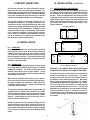
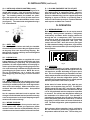
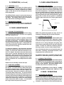
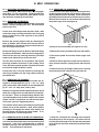
Traulsen & Co., Inc.
Quality Refrigeration
OWNER’S MANUAL
Instructions for the installation, operation
and maintenance of all Traulsen:
UC Series Full-Size Undercounter Refrigerators
UC Series Full-Size Undercounter Freezers
UL Series Shorty Cooktop Refrigerators
This Traulsen unit is built to our highest quality standards. We build our refrigerators, freezers and heated
cabinets this way as a matter of pride. This philosophy has made Traulsen the leader in commercial refrigeration since 1938. We thank you for your choice and confidence in Traulsen equipment and we know you
will receive many years of utility from this equipment.
All Traulsen units are placed on a permanent record file with the service department. In the event of any
future questions you may have, please refer to the model and serial number found on the name tag affixed
to the unit. Should you need service, however, call us on our toll free number, 800-825-8220 between 7:30
am and 4:30 pm CST, Monday thru Friday. It is our pleasure to help and assist you in every possible way.
INSTALLER
COMPLETE THE FOLLOWING INFORMATION PRIOR TO UNIT INSTALLATION
INITIAL START DATE:
SERIAL NO.
MODEL TYPE:
COMPANY/INDIVIDUAL NAME:
INSTALLER:
FORM NUMBER TR35745 REV. 5/03
P/N 375-60183-00
TABLE OF CONTENTS
I. THE SERIAL TAG
II. RECEIPT INSPECTION
III. INSTALLATION
a-Location
b-Packaging
c-Installing Legs
d-Installing Casters
e-Shelf Pins
f-Cord & Plug
g-Power Supply
h-Wiring Diagram
i-Placing Equipment On Top Of Cabinet
IV. OPERATION
a-Refrigerators
b-Freezers
c-Condensate Removal
V. CARE & MAINTENANCE
a-Cleaning The Condenser
b-Hinge Replacement
c-Replacing The Gaskets
d-Cleaning The Exterior
e-Cleaning The Interior
VI. MISC. OPERATIONS
a-Adjusting The Shelves
b-Re-Hinging The Door(s)
c-Removing The Drawers
d-Removing The Powerpack
Page 1
Page 2
VII. INTELA-TRAUL
a-Control Features
b-Alarm Explanations
c-Control Panel
d-Parts Assembly
e-Notes To The User
f-Enter The Customer Access Code
g-Customer Service Parameters
h-Adjusting Thermostat Set Point High
i-Adjusting Thermostat Set Point Low
j-Changing The Temperature Scale
k-Setting The 24-Hour Clock
l-Setting The Date
m-Setting Daylight Savings Time
n-Starting A Manual Defrost
o-Setting Defrost Lockouts
p-Adjusting The Dewpoint Compensation Factor
q-Setting The Audible Alarm Style
r-Viewing Sensor Temperatures
VIII. TROUBLE SHOOTING GUIDE
IX. WARRANTY INFORMATION
X. OTHER
a-Service Information
b-Spare Parts
c-Warranty Registration
XI. PARTS LIST
XII. INDEX
Page 2
Page 2
Page 2
Page 3
Page 3
Page 3
Page 3
Page 3
Page 3
Page 3
Page 3/4
Page 4
Page 4
Page 4
Page 4
Page 4
Page 4
Page 4/5
Page 5
Page 5
Page 5/6
Page 7
Page 8
Page 9
Page 9
Page 10
Page 10
Page 11
Page 11
Page 12
Page 12
Page 13
Page 14
Page 14
Page 15
Page 16
Page 17
Page 17
Page 18
Page 19
Page 20
Page 21
Page 21
Page 21
Page 21
Page 22
I. THE SERIAL TAG
The serial tag is a permanently affixed sticker on
which is recorded vital electrical and refrigeration data
about your Traulsen product, as well as the model
and serial number. This tag is located in the right
interior compartment on all full size undercounter and
equipment stand models.
FORT WORTH, TX.
SERIAL
VOLTS
MODEL
Hz
PH
TOTAL CURRENT
AMPS
MINIMUM CIRCUIT
AMPS
MAXIMUM OVERCURRENT PROTECTION
LIGHTS
WATTS
HEATERS
AMPS
AMPS
REFRIGERANT
DESIGN PRESSURE
TYPE
HIGH
OZ
LOW
REFRIGERANT
DESIGN PRESSURE
TYPE
HIGH
OZ
LOW
370-60294-00 REV (A)
-1-
READING THE SERIAL TAG
• Serial = The permanent ID# of your Traulsen
• Model = The model # of your Traulsen
• Volts = Voltage
• Hz = Cycle
• PH = Phase
• Total Current = Maximum amp draw
• Minimum Circuit = Minimum circuit ampacity
• Lights = Light wattage
• Heaters = Heater amperage (Hot Food units only)
• Refrigerant = Refrigerant type used
• Design Pressure = High & low side operating
pressures and refrigerant charge
• Agency Labels = Designates agency listings
II. RECEIPT INSPECTION
III. INSTALLATION (continued)
All Traulsen products are factory tested for performance and are free from defects when shipped. The
utmost care has been taken in crating this product to
protect against damage in transit. All interior fittings
have been carefully secured and the legs or casters
are boxed and strapped inside to prevent damage.
III. c - INSTALLING LEGS OR CASTERS:
6” high stainless steel legs are supplied standard for
all Traulsen undercounter units. Casters in lieu of legs
are available as an optional accessory for the same
models. These are shipped from the factory packed
inside two cardboard boxes which are strapped to one
of the shelves. Remove the nylon straps and open the
boxes, each should contain either four (4) legs or four
(4) casters and sixteen (16) bolts (see figure 1 for
proper locations).
You should carefully inspect your Traulsen unit for
damage during delivery. If damage is detected, you
should save all the crating materials and make note
on the carrier’s Bill Of Lading describing this. A freight
claim should be filed immediately. If damage is subsequently noted during or immediately after installation, contact the respective carrier and file a freight
claim. Under no condition may a damaged unit be returned to Traulsen & Co. without first obtaining written permission (return authorization).
One Section Models
Two Section Models
III. INSTALLATION
III. a - LOCATION:
Select a proper location for your Traulsen unit, away
from extreme heat or cold. Allow enough clearance
between the unit and the side wall in order to make
use of the door stay open feature at 120° (self-closing
feature operates up to 90°). The door(s) must be able
to open a minimum of 90° in order to make use of the
maximum clear door width.
Three Section Models
Fig. 1
Proper Leg/Caster Locations
III. b - PACKAGING:
All Traulsen units are shipped from the factory bolted
to a sturdy wooden pallet and packaged in a durable
cardboard container. The carton is attached to the
wooden skid with the use of large staples. These
should first be removed to avoid scratching the unit
when lifting off the crate.
WARNING: THE CABINET MUST BE BLOCKED AND
STABLE BEFORE INSTALLING LEGS OR CASTERS.
To install the legs or casters, first raise and block the
reach-in a minimum of 7” from the floor. For installing legs, thread the legs into the threaded holes on
the bottom of the cabinet (see figure 2). Be certain
that all legs are tightly secured (legs and casters
should be tightened to 300 inch/pounds, max). When
the unit is set in its final position, it is important for
proper operation that the unit be level. The legs are
adjustable for this purpose, turn the bottom of the leg
counter-clockwise to raise it, clockwise to lower it.
Level the unit from front to back as well as side to side
in this manner, using a level placed in the bottom of
the cabinet.
Most exterior stainless steel surfaces have a protective vinyl covering to prevent scratching during manufacturing, shipping and installation. After the unit is
installed in place of service, remove and discard the
covering from all surfaces.
To remove the wooden pallet, first if at all possible, we
suggest that the cabinet remain bolted to the pallet
during all transportation to the point of final installation. The bolts can then be removed with a 3/4” socket
wrench. Avoid laying the unit on its front, side or
back for removal of the pallet.
NOTE: Traulsen does not recommend laying the unit
down on its front, side or back. However, if you must
please be certain to allow the unit to remain in an upright position afterwards for 24 hours before plugging
it in so that the compressor oils and refrigerant may
settle.
Fig. 2
-2-
III. INSTALLATION (continued)
III. d - INSTALLING LEGS OR CASTERS (cont’d):
Please note that Traulsen units are not designed to be
moved while on legs. If the unit requires moving, a
pallet jack or forklift should be used to prevent damage. For installing casters, the casters are “plate”
type, and require the use of four (4) bolts each to secure them firmly to the cabinet bottom at each corner
(see figure 3). The caster bolts are tightened using a
1/2” socket wrench.
III. i - PLACING EQUIPMENT ON TOP OF UNIT:
Equipment may be placed on top of your Traulsen fullsize undercounter or equipment stand. However,
please be aware that a stainless steel worktop is required on cabinets being used to support equipment
weighing in excess of 100 lbs. or producing heat in
excess of 140°F to the top surface. Optional stainless
steel tops are available from Traulsen.
IV. OPERATION
IV. a - REFRIGERATORS:
Both refrigerators and freezers do not require manual
defrosting. During normal operation, a refrigerator
continuously circulates above freezing cabinet air
through the coil. A compressor “OFF” cycle occurs
every hour to melt any frost which may accumulate
on the coil during the compressor “ON” cycle. The
control will read “dEF” when this occurs (see figure
4). With standard holding refrigerators, high relative
humidity is also maintained to prevent dehydration of
stored product.
Fig. 3
III. e - SHELF PINS:
The unit ships with shelves and shelf pins installed.
Check all shelf pins to assure they are tightened down
as they may have come loose during shipping. Rotate the pins clockwise until they are secured against
the side of the cabinet.
FREEZER
INTELA-TRAUL
III. f - CORD & PLUG:
Most self-contained models are supplied with a cord
& plug attached. It is shipped coiled at the rear of the
cabinet, secured by a nylon strip. For your safety and
protection, all units supplied with a cord and plug include a special three-prong grounding plug on the service cord. Select only a dedicated electrical outlet with
grounding plug for power source. NOTE: Do not under any circumstances, cut or remove the round
grounding prong from the plug, or use an extension
cord.
°F
°C
SET
Fig. 4
IV. b - FREEZERS:
During normal operation, a freezer continuously circulates below freezing cabinet air through the coil. The
coil requires a periodic defrosting for proper operation. This is accomplished by an automatic, time activated, temperature/time terminated, defrost program,
utilizing hot gas from the refrigeration system. The
controller is preset at the factory for six equally spaced
defrost cycles within each 24-hour period.
III. g - POWER SUPPLY:
The supply voltage should be checked prior to connection to be certain that proper voltage for the cabinet wiring is available (refer to the serial tag to determine correct unit voltage). Make connections in accordance with local electrical codes. Use qualified
electricians.
At the start of a freezer defrost cycle, both the compressor and evaporator fans are OFF. The INTELATRAUL control will read “dEF” (see figure 4). When a
temperature device affixed to the coil senses 70°F, the
coil is fully defrosted and the compressor operation
is resumed. The coil fans are delayed from starting at
the termination of a defrost cycle. Fan operation is
automatically resumed, they can also be started by a
time or temp delay (whichever comes first). In case of
temp delay, it uses the same coil sensor and starts at
32°F. The total refrigeration system operation is then
resumed.
Use of a separate, dedicated circuit is required. Size
wiring to handle indicated load and provide necessary
overcurrent protector in circuit (see amperage requirements on the unit’s serial tag).
III. h - WIRING DIAGRAM:
Refer to the wiring diagram for any service work performed on the unit. Should you require one, please
contact Traulsen Service at (800) 825-8220, and provide the model and serial number of the unit involved.
During freezer defrost operation, heat is confined to
the coil enclosure to prevent any significant rise in
temperature within the food zone. The fan delay con
-3-
IV. OPERATION (continued)
V. CARE & MAINTENANCE
IV. b - FREEZERS (cont’d):
trols function upon termination of a defrost cycle is
two-fold. First, to prevent blowing warm air into the
food storage area. Second, to prevent any condensation on the defrost coil from being blown into the
food storage area.
V. c - REPLACING THE GASKETS:
To remove the gasket to be replaced, grasp it firmly by
one corner and pull it out. Before attempting to install
a new gasket, both the unit and the gasket itself must
be at room temperature. Insert the four corners first
by using a rubber mallet (or hammer with a block of
wood). After the corners are properly inserted, work
your way towards the center from both ends by gently
hitting with a mallet until the gasket is completely
seated in place (see figure 5 for proper gasket placement).
The INTELA-TRAUL control is set from the factory to
terminate defrost at 20 minutes in the event of a sensor failure. This setting should never be tampered
with, without first consulting the factory.
○
IV. c - CONDENSATE REMOVAL:
Both refrigerator and freezer units are supplied with
an electric condensate evaporator for condensate removal.
○
○
Inside Door Panel
Gasket Assembly
○
Fig. 5
○
○
○
○
V. CARE & MAINTENANCE
Vertical Gasket
Retainer
○
○
○
○
○
○
V. a - CLEANING THE CONDENSER:
The most important thing you can do to insure a long,
reliable service life for your Traulsen is to regularly
clean the condenser coil.
NOTE: The gasket may appear too large, but if it is
installed as indicated above it will slip into place.
V. d - CLEANING THE EXTERIOR:
Exterior stainless steel should be cleaned with warm
water, mild soap and a soft cloth. Apply with a dampened cloth and wipe in the direction of the metal grain.
The condensing unit requires regularly scheduled
cleaning to keep the finned condenser clean of lint
and dust accummulation. The INTELA-TRAUL control will notify you through a “CLN-FIL” message when
cleaning is necessary (see page 7). Keeping the condenser clean allows the cabinet to operate more efficiently and use less energy.
Avoid the use of strong detergents and gritty, abrasive cleaners as they may tend to mar and scratch the
surface. Do NOT use cleansers containing chlorine,
this may promote corrosion of the stainless steel.
To clean the condenser, first disconnect electrical
power to the cabinet and remove the front louver assembly. To remove this, follow the directions in section VI. d - Step #1. Once the screws are removed, the
panel can be removed allowing full access to the
powerpack. Vacuum or brush any dirt, lint or dust
from the finned condenser coil, the compressor and
other cooling system parts. If significant dirt is clogging the condenser fins, use compressed air to blow
this clear.
Care should also be taken to avoid splashing the unit
with water, containing chlorinated cleansers, when
mopping the floor around the unit.
For stubborn odor spills, use baking soda and water
(mixed to a 1 TBSP baking soda to 1 pint water ratio).
V. e - CLEANING THE INTERIOR:
For cleaning both stainless steel and anodized aluminum interiors, the use of baking soda as described in
section “V. d” is recommended. Use on breaker strips
as well as door gaskets. All interior fittings are removable without tools to facilitate cleaning.
Replace louver assembly, screws and caps.
V. b - HINGE REPLACEMENT:
Both the door and hinge can be easily removed from
the cabinet. To remove the door, remove the plug at
the bottom of the top hinge. Inside the hinge there is
a small screw which secures the door in place. Remove this with a flat head screwdriver and the door
can then be lifted off the hinge. To remove the door
half of the hinge from the door, lift off the hinge cover
and then remove the three Phillips head screws which
secure the hinge in place on the door. To remove the
cabinet half of the hinge, remove the three Phillips
head screws which hold it in place. To reassemble
the hinge reverse the previous procedure.
WARNING: DISCONNECT ELECTRICAL POWER
SUPPLY BEFORE CLEANING ANY PARTS OF THE
UNIT.
VI. MISC. OPERATIONS
-4-
VI. a - ADJUSTING THE SHELVES:
For shelves mounted on pins, first select the desired
location and remove the white plastic covers in the
interior back and sides by rotating them counter-clockwise. Remove the shelf pins by rotating them counterclockwise. Install the pins in the desired location by
VI. MISC. OPERATIONS
VI. a - ADJUSTING THE SHELVES (cont’d):
rotating clockwise. Make sure the pin is securely tightened down. Do not over tighten. Slide the shelf into
its new position, and replace the white plastic covers
into the holes vacated by the shelf pins.
VI. d - REMOVING THE POWERPACK:
1. Remove the louver panel by first removing the four
(4) black plastic plugs that are located in each corner
of the powerpack louver assembly. These conceal four
(4) Phillips head screws which hold the louver in place.
Remove these screws as well, and set both them and
the plastic plugs aside (see figure 6).
VI. b - REHINGING THE DOOR(S):
All UC models are supplied standard with a re-hinging
feature. To begin rehinging the door, first disconnect
power to the unit.
Lift the door off its hinge cams and place aside. Next
remove the plugs covering the holes of the re-hinging
feature located on the side opposite of the present
hinge location.
○
○
○
○
○
○
○
○
Remove the existing hinge bodies by removing the
three (3) Phillips head screws which secure each to
the cabinet face. Replace the hinges in their new location, and replace the screws.
Fig. 6
2. Remove louver assembly (see Figures 7a & 7b).
Remove the hinge cover from the door half of the hinge
by sliding it downwards. Next remove the hinge hardware from the door by removing the three (3) Phillips
head screws which secure each to the door.
3. Remove the power cord blank-off cover and retainer.
Turn the door around to its new position, and replace
the hinge hardware to the door in the existing screw
holes, but in the opposite position. Replace the screws
to secure the hinge hardware in place.
5. Remove interior plenum on back wall of cabinet interior, air duct transition, supply air duct and return air
grill.
4. Disconnect power and mullion heater plugs from
chassis.
6. Remove the four (4) Phillips head screws securing
the powerpack to the cabinet front (see figure 8).
Position the door in its new location by lowering the
door hinge hardware into the hinge cams located on
the cabinet face.
VI. c - REMOVING THE DRAWERS:
Each drawer on UL equipment stand models are designed to accommodate two (2) 12” x 20” x 4” deep
pans, front to back. SBS models can acommodate two
(2) 12” x 20” x 4” deep pans, side by side.
Drawers are supplied standard with divider bars which
allow it be configured for use with half, third and quarter size pans. These are shipped along with the cabinet, taped together and secured inside of the bottom
drawer. No bar is required for use with full-size pans.
In all cases, pans are supplied by others.
○
○
○
The drawers can be easily removed by first pulling the
drawer out to its full extension. Next, lift the drawer
vertically to dis-engage the drawer slide wheel from
the slide frame and remove the entire drawer. To replace the drawer, reverse the process.
VI. d - REMOVING & RELOCATING THE POWERPACK:
To remove the powerpack for maintenance, servicing
or to relocate it to the other side, first disconnect power
to the unit. If the unit is equipped with an optional
stainless steel top, this will also first have to be removed. Then follow these directions:
○
○
○
○
○
○
○
○
○
Fig. 8
○
○
7. Grasp the condenser fan mounting brace and pull
the powerpack up and out gently. This allows the unit
to come forward enough so as to enable the powerpack
to be pulled out of the top and bottom lip brackets (see
figure 9).
-5-
VI. MISC. OPERATIONS (cont’d)
Fig. 7a
Remove Louver
Assembly
○
○
○
○
○
○
○
○
○
○
○
○
○
○
○
○
○
○
○
○
Fig. 7b
○
○
○
○
○
○
○
○
○
○
○
○
○
○
○
○
○
○
○
○
○
○
○
○
○
○
○
○
○
○
○
○
○
○
○
○
○
○
○
○
○
○
○
○
○
○
○
○
○
○
○
○
Fig. 9
Removing Power
Pack
-6-
VII. INTELA-TRAUL®
Your new Traulsen Undercounter Refrigerator or Freezer is equipped with a state-of-the-art electronic microprocessor INTELA-TRAUL® control, which precisely regulates operation and provides alarms when problems occur. It is
supplied from the factory completely ready for use but without the audible alarms activated. See pages 8 thru 17 for
more information.
VII. a - INTELA-TRAUL® CONTROL FEATURES:
Internal Time Clock
• Eliminates defrost time clock.
• Will display only at “Start Up”.
• Must be reset after a power failure.
• See “Setting The 24-Hour Clock” on Page 12 (Also required at “Start Up”).
• Will automatically update for Daylight Savings Time. See “Setting Daylight Savings Time” on page 13.
Water Resistant Housing
The INTELA-TRAUL® control is water resistant not only from the face of the control, but also from the rear of the
housing.
Parameter/Service Levels
• See “Customer / Service Parameters” on Page 9.
Defrost Lockouts - See “Setting Defrost Lockouts” on page 15.
• Customers can set up to 4 different defrost lockout periods. The lockout prevents the unit from going into a defrost
cycle during peak kitchen use. Note: The 24-hour clock must be set for this feature to operate correctly.
Data Storage
The control comes equipped with 72 hours worth of data storage capability including:
• Records cabinet air temperatures every 6 minutes, needed to document “Due Diligence” in accordance with
HAACP standards.
• Records alarm events.
• Records diagnostic test of each sensor every 24 hours.
• Records failed security attempts.
• Records door open cycles.
• Records defrost cycles (refrigerator and freezer models only).
Note: The 24-hour clock and the date must be set for the above information to be recorded at the correct time
and date.
Communication Ability
An RS485 port is available as a means of retrieving information from the stored data.
Smart Recovery
In the event that a sensor fails, the INTELA-TRAUL® control will maintain the same compressor operation & defrost
cycles that it recorded over the previous 72 hours in order to maintain the operation of the unit until service arrives.
Alarms (See the following pages for explanations)
• High Cabinet Air Temperature
• Low Cabinet Air Temperature
• Loss Of Power
• CONDENSERCLEAN*
• Sensor Failures
* Not Available On Remote Models
-7-
VII. INTELA-TRAUL® (continued)
VII. b - ALARM EXPLANATIONS:
*NOTE: Explanation of alarms assume the audible alarm style is set at a 3-second burst or a
continuous audible alarm. References to the audible alarm do not apply if the audible alarm
style is set to OFF (Refer to page 17 for setting the audible alarm style).
High Cabinet Air Temperature: The audible alarm* will sound and the display will read HI
CAb when the temperature inside the cabinet rises above a pre-programmed limit. The limit is
determined by the type of unit being operated (i.e.: refrigerator/freezer). To turn off the audible
alarm*, press the alarm cancel button. The visual alarm text will continue to display until the
cabinet air temperature falls below the limit. If the temperature does not fall below the limit
within 5 minutes, the audible alarm* will sound again and an additional Call Service message
will display.
POSSIBLE CAUSES:
• Doors open for extended periods of time.
• Large amounts of hot product placed inside the cabinet.
• Condenser coil dirty.
Low Cabinet Air Temperature: The audible alarm* will sound and the display will read Lo
Cab when the temperature inside the cabinet falls below a pre-programmed limit. The limit is
determined by the type of unit being operated (i.e.: refrigerator/ freezer). To turn off the audible
alarm*, press the alarm cancel button. The visual alarm text will continue to display until the
cabinet air temperature rises above the limit. If the temperature does not rise above the limit
within 5 minutes, the audible alarm* will sound again and an additional Call Service message
will display.
POSSIBLE CAUSES:
• No product in unit.
• Failed sensors.
Loss Of Power: The audible alarm* will sound and the display will read Electrical Loss, when
the unit regains power after an outage. To turn off the audible alarm* and/or clear the visual
text, press the alarm cancel button. You must reset the clock and date if you are using any
defrost lockouts or are retrieving the information from the data storage memory. See “Setting
The 24-Hour Clock” page 12 and “Setting the Date” page 13.
System Leak: The audible alarm* will sound and the display will read Call Service, when the
control detects a leak in the refrigeration system. To turn off the audible alarm*, press the alarm
cancel button. The visual alarm text will remain until a service technician has repaired the unit.
If the condition remains for 24 hours, the audible alarm* will sound again.
POSSIBLE CAUSES:
• Low refrigerant charge.
• Discharge sensor has failed low.
CONDENSERCLEAN: The audible alarm* will sound and the display will read Clean
Filter, when the operating pressures and temperatures exceed a safe operating range. As the
load on the condenser decreases, the alarm will turn off by itself. As the pressures on the
condenser continues to rise, the audible alarm* will stay on for longer periods of time. To turn
off the audible alarm*, press the alarm cancel button. The visual alarm text will remain until the
filter/condenser has been cleaned. If the condition remains for 24-hours, the audible alarm* will
sound again and visual display will read Call Service.
POSSIBLE CAUSES:
• Inadequate air flow through condenser unit.
• Discharge sensor has failed high.
Sensor Failures: The audible alarm* will sound and the display will read Sensor Failure Call
Service, when any of the unit sensors fail to operate. To turn off the audible alarm*, press the
alarm cancel button. The visual alarm text will remain until the sensor has been replaced.
Depending on the function of the sensor, the audible alarm* will sound again in either 5 minutes
or 24 hours.
*Not available on remote models.
-8-
VII. INTELA-TRAUL® (continued)
VII. c - CONTROL PANEL:
LED FOR ° F
LED FOR °C
3-DIGIT (RED)
LED DISPLAY
FREEZER
INTELA-TRAUL
°F
°C
SET
DEFROST
ICON
W / LED
ALARM CANCEL
BUTTON
VII. d - PARTS ASSEMBLY: (UC/UL Cabinets)
COIL SENSOR*
337-60071-00
DISCHARGE SENSOR*
337-60072-00
(refrigerator & freezer only)
(refrigerator & freezer only)
HORN*
337-60070-00
CABINET SENSOR*
337-60069-00
HORN
INTELA-TRAUL**
HORIZONTAL
CONTROLLER
337-60062-00
DISCHARGE LINE
HOLDER CLIP*
377-60038-00
EVAP COIL
NOT USED
CABINET AIR
NOT USED
HOLDER CLIP
TRANSFORMER/RS485
DEFROST COMPRESSOR
RELAY POWER LINE IN 2
DOOR HEATER
EVAP BLOWER RELAY
POWER IN LINE 1
-9-
*= Can be ordered seperately
**=Requires unit Model No. & S/N to place order.
VII. INTELA-TRAUL® (continued)
VII. e - NOTES TO THE USER:
You only have 20-30 seconds between button pushes. If you take longer than 30 seconds, the controller will revert back to
displaying the cabinet temperature. If you enter the wrong security code, the controller will revert back to displaying the
cabinet temperature. You can exit the parameters at any time by pressing the alarm cancel button or by waiting 20-30
seconds.
VII. f - ENTER THE CUSTOMER ACCESS:
Use the security code 0, A, 1
Press the set button SET .
and the following instructions:
The display will read
Customer/Service Access.
Press the set button SET .
The display will show three zeros with the left zero flashing
Press the set button SET .
The display will show three zeros with the center zero flashing
Press the down arrow key
to sequence through F, E, d, C, b, A, 9, 8, 7,…etc.
When you reach A press set SET .
The display will show zero, A, zero with the right zero flashing
Press the up arrow key
to sequence through 1, 2, 3, 4, 5, 6, 7, 8, 9, A, b,…etc.
When you reach 1 press set SET .
The display will read
.
Thermostat Set Point High.
You are now in the CUSTOMER / SERVICE PARAMETERS.
-10-
VII. INTELA-TRAUL® (continued)
VII. g - CUSTOMER SERVICE PARAMETERS:
Listed below are the available parameters in the order they appear, using the down arrow key on the
controller. You can use either the up or down arrow keys to scroll through the options.
Thermostat Set Point High
Defrost Lockout 2
Thermostat Set Point Low
Defrost Lockout 3
Temperature Scale
Defrost Lockout 4
Audible Alarm Style
Room Temperature Offset
Time (24-hour clock)
Ambient Air Sensor
Date (month - day - year)
Evaporator Coil Sensor
Daylight Savings
Discharge Line Sensor
Start Manual Defrost
Relative Humidity Sensor
Defrost Lockout 1
VII. h - ADJUSTING THE THERMOSTAT SET POINT HIGH:
This parameter sets the high point of the desired cabinet temperature range. Typically, freezers will
range from -3° F to 0° F (-19° C to –18° C) and refrigerators will range from 36° F to 40° F (2° C to 4° C)
for this parameter setting. This parameter is preset at the factory and does not have to be adjusted
unless the customer chooses to do so. Note: Set Point Low and Set Point High cannot be set to the
same temperature. There will be at least 1-2 degree difference between the two settings.
Follow the instructions to enter the customer access code on page 9. When the control
display reads
Thermostat Set Point High. Press the set button SET .
Use the arrow keys
to adjust the temperature to your desired setting.
When the display shows the temperature you want press the set button SET .
The display will then read
Thermostat Set Point High.
You can use the up or down arrow keys to scroll to the next parameter
or press the alarm cancel button to exit
) .
))
-11-
VII. INTELA-TRAUL® (continued)
VII. i - ADJUSTING THE THERMOSTAT SET POINT LOW:
This parameter sets the low point of the desired cabinet temperature range. Typically, freezers will range
from –6° F to -4° F (-21° C to –20° C) and refrigerators will range from 32° F to 34° F ( 0° C to 1° C) for
this parameter setting. This parameter is preset at the factory and does not have to be adjusted unless
the customer chooses to do so. Note: Set Point Low and Set Point High cannot be set to the same
temperature. There will be at least 1-2 degree difference between the two settings.
Follow the instructions to enter the customer access code on page 9. When the control
displays
Thermostat Set High, press the down arrow key
display reads
until the control
Thermostat Set Point Low. Press the set button SET .
Use the arrow keys
to adjust the temperature to your desired setting.
When the display shows the temperature you want press the set button SET .
The display will then read
Thermostat Set Point High.
You can use the up or down arrow keys to scroll to the next parameter
or press the alarm cancel button to exit
) .
))
VII. j - Changing The Temperature Scale:
The temperature scale determines if the temperature displayed will be in degrees
Fahrenheit or degrees Celsius.
Follow the instructions to enter the customer access code on page 9. When the control
displays
Thermostat Set High, press the down arrow key
display reads
Temperature Scale. Press the set button SET .
The display will start with the current setting either
or
until the control
for degrees Fahrenheit
for degrees Celsius. Use the arrow keys
to toggle between the options.
When the display shows the scale you want press the set button SET .
The display will then read
Thermostat Set Point High.
You can use the up or down arrow keys
or press the alarm cancel button to exit
to scroll to the next parameter
) .
))
-12-
VII. INTELA-TRAUL® (continued)
VII. k - SETTING THE 24-HOUR CLOCK:
The internal timeclock must be set in order for the data storage memory to correctly log events and to
allow any defrost lockout to occur at the correct time of day. If the clock is not set, the control assumes
the time is 12 am at the time power is supplied to the unit. The hours on a 24-hour time clock read the
following way:
H01 = 1:00 a.m.
H02 = 2:00 a.m.
H03 = 3:00 a.m.
H04 = 4:00 a.m.
H05 = 5:00 a.m.
H06 = 6:00 a.m.
H07 = 7:00 a.m.
H08 = 8:00 a.m.
H09 = 9:00 a.m.
H10 = 10:00 a.m.
H11 = 11:00 a.m.
H12 = 12:00 p.m.
H13 = 1:00 p.m.
H14 = 2:00 p.m.
H15 = 3:00 p.m.
H16 = 4:00 p.m.
H17 = 5:00 p.m.
H18 = 6:00 p.m.
H19 = 7:00 p.m.
H20 = 8:00 p.m.
H21 = 9:00 p.m.
H22 = 10:00 p.m.
H23 = 11:00 p.m.
H24 = 12:00 a.m.
Follow the instructions to enter the customer access code on page 9. When the control
displays
Thermostat Set High, press the down arrow key
display reads
until the control
Clock. Press the set button SET .
The display will show
Hours. The right two numbers will be flashing.
Use the arrow keys
to set the hour.
When the correct hour is displayed, press the set button SET .
The display will show
Minutes. The right two numbers will be flashing.
Use the arrow keys to set the minutes
.
When the correct minutes are displayed, press the set button SET .
The display will then read
Thermostat Set Point High.
You can use the up or down arrow keys
or press the alarm cancel button to exit
to scroll to the next parameter
) .
))
-13-
VII. INTELA-TRAUL® (continued)
VII. l - SETTING THE DATE:
The date must be set in order for the data storage memory to correctly log events. Follow the instructions to enter the customer access code on page 9. When the control displays
Set Point High, press the down arrow key
until the control display reads
the set button SET . The display will show
Press the arrow keys
Thermostat
Date. Press
(year). The right two numbers will be flashing.
to set the year. When the correct year is displayed, press the set
button SET . The display will show
(month). The right two numbers will be flashing. Use
the arrow keys
When the correct month is displayed, press the set
button SET .
The display will show
the arrow keys
SET
to set the month.
to set the day.
. The display will then read
arrow keys
(day). The right two numbers will be flashing. Press
When the correct day is displayed, press the set button
Thermostat Set Point High. You can use the up or down
to scroll to the next parameter, press the alarm cancel button to exit
) .
))
VII. m - SETTING DAYLIGHT SAVINGS TIME:
This parameter is preset at the factory to automatically adjust the 24-hour clock for Daylight Savings
Time. Follow the instructions to enter the customer access code on page 9. When the control displays
Thermostat Set Point High, press the down arrow key
until the display reads
Daylight Savings Time. Press the set button SET . The display will show
light Savings Time (Yes, automatically adjust for Daylight Savings Time).
button SET , for “NO” press the up or down arrow key
For “YES” press the set
. The display will read
Dayligt Savings Time (no). Press the set button SET . The display will read
Set Point High. You can press the the up or down arrow keys
eter or press the alarm cancel button to exit
).
))
-14-
Day-
Thermostat
to scroll to the next param-
VII. INTELA-TRAUL® (continued)
VII. n - STARTING A MANUAL DEFROST CYCLE:
This parameter allows a service technician to start a defrost cycle at any time. This parameter
will override any lockout settings.
Follow the instructions to enter the customer access code on page 9. When the control
displays
Thermostat Set High, press the down arrow key
display reads
until the control
Start Manual Defrost.
Press the set button SET .
The display will show
(NO).
Press either arrow key
(YES).
The display will show
.
Press the set button SET .
The display will then read
Thermostat Set Point High.
You can use the up or down arrow keys
or press the alarm cancel button to exit
FREEZER
°C
) .
))
The defrost icon will be lit,
INTELA-TRAUL
°F
to scroll to the next parameter
SET
and the display will read
when the unit is in defrost.
DEFROST ICON
NOTE: Traulsen refrigerator units also have an off-cycle defrost once an hour, at which time the
control will read
. This defrost is temperature terminated and can last from 3 - 10
minutes (dEF will be displayed for 22-27 minutes time).
-15-
VII. INTELA-TRAUL® (continued)
VII. o - SETTING THE DEFROST LOCKOUTS:
The defrost lockout parameters allow the customer to prevent the unit from going into a defrost cycle for
two hours during a set timeframe. Customers can set up to four defrost lockout parameters. They are all
programmed the same way. The parameters will be set for the time the lockout is to start. The controller
automatically calculates 2 hours from that setting. The options are similar to the 24-hour clock settings
and are in 30-minute increments. Each of the lockout parameters covers 6 hours of the 24-hour clock.
Note: The 24-hour clock must be set for this feature to operate at the correct time of day. See “Setting
the 24-Hour Clock” on page 12.
Sample:
OFF
020 = 2:00 a.m.
023 = 2:30 a.m.
030 = 3:00 a.m.
033 = 3:30 a.m.
040 = 4:00 a.m.
043 = 4:30 a.m.
050 = 5:00 a.m.
053 = 5:30 a.m.
060 = 6:00 a.m.
063 = 6:30 a.m.
070 = 7:00 a.m.
073 = 7:30 a.m.
080 = 8:00 a.m.
OFF
080 = 8:00 a.m.
083 = 8:30 a.m.
090 = 9:00 a.m.
093 = 9:30 a.m.
100 = 10:00 a.m.
103 = 10:30 a.m.
110 = 11:00 a.m.
113 = 11:30 a.m.
120 = 12:00 p.m.
123 = 12:30 p.m.
130 = 1:00 p.m.
133 = 1:30 p.m.
140 = 2:00 p.m.
OFF
OFF
140 = 2:00 p.m.
200 = 8:00 p.m.
143 = 2:30 p.m.
203 = 8:30 p.m.
150 = 3:00 p.m.
210 = 9:00 p.m.
153 = 3:30 p.m.
213 = 9:30 p.m.
160 = 4:00 p.m.
220 = 10:00 p.m.
163 = 4:30 p.m.
223 = 10:30 p.m.
170 = 5:00 p.m.
230 = 11:00 p.m.
173 = 5:30 p.m.
233 = 11:30 p.m.
180 = 6:00 p.m.
240* = 12:00 a.m.
183 = 6:30 p.m.
243* = 12:30 a.m.
190 = 7:00 p.m.
010 = 1:00 a.m.
193 = 7:30 p.m.
013 = 1:30 a.m.
200 = 8:00 p.m.
020 = 2:00 a.m.
* Denotes not available.
A lockout can not be programmed to start at 12:00 am or 12:30 am due to conflicts with other internal
programs. The defrost lockouts can not be programmed to run back-to-back. For example, if dL1 is
set to 080, then a defrost cycle would be locked out from 8:00 am to 10:00 am. Because of the dL1
setting the dL2 parameter would not let the user choose a lockout start time before 10:30 am. All
lockouts are preset at the factory to OFF.
Follow the instructions to enter the customer access code on page 9. When the control
displays
Thermostat Set High, press the down arrow key
control display reads
The display will show
or
Off. Press the arrow keys
until the control the
. Press the set button SET .
to set the start time.
When the correct time is displayed, press the set button SET .
The display will then read
Thermostat Set Point High.
You can press the up or down arrow keys
or press the alarm cancel button to exit
to scroll to the next parameter
) .
))
-16-
VII. INTELA-TRAUL® (continued)
VII. p - ADJUSTING THE ROOM TEMPERATURE OFFSET:
The room temperature offset parameter allows a service technician or end user the ability to have the
display show a temperature that is within three degrees of the actual temperature being read by the
cabinet air sensor. This allows for continuity of reading between different temperature reading devices.
(i.e.: thermistor Vs thermocouple Vs handheld thermometer) This parameter is preset at the factory to
“0” or no offset.
Follow the instructions to enter the customer access code on page 9. When the control displays
Thermostat Set High, press the down arrow key
Room Temperature Offset. Press the set button SET .
until the control display reads
Use the arrow keys
to adjust the
offset to your desired setting. When the display shows the offset you want press the set button SET .
The display will then read
keys
Thermostat Set Point High. You can use the up or down arrow
to scroll to the next parameter or press the alarm cancel button to exit
) .
))
VII. q - SETTING THE AUDIBLE ALARM STYLE:
This parameter will allow the customer to turn on/off the audible alarm feature on the INTELATRAUL® control. The audible alarm is preset from the factory to OFF. The customer can choose
between an audible alarm that sounds for 3 seconds then automatically turns off, or a continuous
audible alarm that must be manually acknowledged. Regardless of this feature’s setting, visual alarm
text will display when conditions warrant.
To adjust this setting, follow the instructions to enter the customer access code on page 9. When the
control displays
reads
Thermostat Set Point High, press the up arrow key
until the display
Audible Alarm Style. Press the set button SET . The display will read
Use the arrow keys
to scroll between
OFF.
for the 3-Second Audible Alarm Burst or
for Continuous Audible Alarm. When the display shows your choice of style, press the set
button SET . The display will then read
thermostat Set Point High. Use the arrow keys
to scroll to the next parameter or press the Alarm Cancel Button
-17-
) to exit.
))
VII. INTELA-TRAUL® (continued)
VII. r - VIEWING SENSOR TEMPERATURES:
These parameters allow a service technician or customer to view the temperature of all sensors
within the unit. The temperatures cannot be adjusted.
Follow the instructions to enter the customer access code on page 9. When the control displays
Thermostat Set Point High
Evaporator Coil Sensor
, press the DOWN arrow key
or Disharge Line Sensor
The display will read Thermostat Set Point High
Press the UP or DOWN arrow keys
CANCEL button
unit the display reads
or press the SET button SET .
.
to scroll through the parameters or press the ALARM
) to exit.
))
-18-
VIII. TROUBLE SHOOTING GUIDE
FIND YOUR PROBLEM HERE
REMEDY
1. Condensing unit fails to start.
a.
b.
Check if cord & plug has been disconnected.
Check INTELA-TRAUL® temperature setting.
2. Condensing unit operates for
prolonged periods or continuously.
a.
b.
c.
Are doors closing properly?
Dirty condenser or filter. Clean properly.
Evaporator coil iced. Needs to defrost. See
instructions for setting a manual defrost cycle
on page 15.
Shortage of refrigerant, call service.
d.
3. Food compartment is too warm.
a.
b.
Check door(s) and gasket(s) for proper seal
Perhaps a large quantity of warm food has
recently been added or the door was kept
open for a long period of time, in both
cases, allow adequate time for the cabinet
to recover its normal operating temperature.
INTELA-TRAUL® setting too high, readjust
per instructions on page 11.
c.
4. Food compartment is too cold.
a.
Perhaps a large quantity of very cold or frozen
food has recently been added. Allow adequate
time for the cabinet to recover its normal operating
temperature.
Adjust the INTELA-TRAUL® to a warmer
setting, see page 12.
b.
5. Condensation on the exterior surface.
a.
b.
Check door alignment and gaskets for proper seal.
Condensation on the exterior surface of the
unit is perfectly normal during periods of
high humidity.
6. Compressor hums but does not start.
a.
Call for service.
-19-
IX. WARRANTY INFORMATION
STANDARD DOMESTIC WARRANTY
TRAULSEN & CO., INC. warrants new equipment to the original purchaser, when installed within the United States
against defective material and workmanship for one (1) year from the date of original installation. Under this warranty,
TRAULSEN & CO., INC. will repair or replace, at its option, including service and labor, all parts found to be defective
and subject to this warranty. The compressor part is warranted for an additional four (4) years. During this period
TRAULSEN & CO., INC. will supply replacement compressor(s) if deemed defective, however, all installation, recharging and repair costs will remain the responsibility of the owner.
This warranty does not apply to damage resulting from fire, water, burglary, accident, abuse, misuse, transit, acts of
God, terrorism, attempted repairs, improper installation by unauthorized persons, and will not apply to food loss.
For Traulsen units purchased with a remote feature, standard warranty will apply only to those components contained within the unit to the point of connection of the refrigeration linesleading to the remote compressor.
THERE ARE NO ORAL, STATUTORY OR IMPLIED WARRANTIES APPLICABLE TO TRAULSEN, INCLUDING BUT NOT
LIMITED TO, ANY IMPLIED WARRANTY OF MERCHANTABILITY OR FITNESS FOR ANY PARTICULAR PURPOSE WHICH
EXTEND BEYOND THE DESCRIPTION ON THE FACE HEREOF. TRAULSEN SHALL HAVE NO OBLIGATION OR LIABILITY FOR CONSEQUENTIAL OR SPECIAL DAMAGES, GROWING OUT OF OR WITH RESPECT TO THE EQUIPMENT OR
ITS SALE, OPERATION OR USE, AND TRAULSEN NEITHER ASSUMES NOR AUTHORIZES ANYONE ELSE TO ASSUME
FOR IT ANY OBLIGATION OR LIABILITY IN CONNECTION WITH THE EQUIPMENT OR ITS SALE, OPERATION OR USE
OTHER THAN AS STATED HEREIN.
INTELA-TRAUL® CONTROL WARRANTY
TRAULSEN & CO., INC. (TRAULSEN), warrants to the original purchaser of the INTELA-TRAUL® control when
installed as part of the Refrigeration/Hot Food Equipment manufactured and sold by TRAULSEN, to be free of defects
in material and workmanship under normal service and use for a period of two (2) years from the date of installation.
Under this warranty statement, TRAULSEN will repair or exchange at TRAULSEN’S discretion, F.O.B. factory, any part
of said control, which proves to be defective. Inspection by the TRAULSEN Service Department of parts claimed
defective shall be final in determining warranty status. The warranty is to include repair or exchange of any defective
In-Warranty control or part(s) of said control for:
Part(s) – Any TRAULSEN INTELA-TRAUL® supplied part(s) found to be defective.
Labor – The labor charges from a TRAULSEN Certified Service Agent to effect the repair or exchange of the defective
part(s).
“Defective Part Return” – All claimed defective part(s) must be returned to TRAULSEN for defect validation within
30 days from the date of the repair. Failure to return all claimed defective part(s) to TRAULSEN will invalidate the
warranty claim, this warranty statement, and forfeit payment for those repairs effected.
This warranty does not apply to damage resulting from fire, water, burglary, accident, abuse, misuse, transit, acts of
God, terrorism, attempted repairs, improper installation by unauthorized persons, and will not apply to food loss,
and will not apply if said equipment is located outside The United States.
INTERNATIONAL COMMERCIAL WARRANTY
(for Canadian warranties see domestic US warranty)
TRAULSEN & CO., INC. warrants to the original purchaser the Refrigeration Equipment manufactured and sold by it to be free from defects in material and
workmanship under normal use and service for a period of one (1) year from date of shipment. Under this warranty, TRAULSEN & CO., INC. will reimburse the
purchaser for the replacement of any part of said equipment (excluding dryers & refrigerant gas) which then proves to be defective. This warranty does not apply
to damage resulting from fire, water, burglary, accident, abuse, misuse, transit, acts of God, terrorism, attempted repairs, improper installation by
unauthorized persons, and will not apply to food loss.
TRAULSEN’S standard warranty does not apply to Export Sales. Rather, for a period of one (1) year from date of original installation not to exceed Fifteen (15)
months from date of shipment from factory, TRAULSEN:
will replace, F.O.B. factory, any defective parts normally subject to warranty.
will not cover the cost of packing, freight or labor such costs being the sole responsibility of the dealer.
THIS WARRANTY IS IN LIEU OF ALL OTHER WARRANTIES EITHER EXPRESSED OR IMPLIED AND CONSTITUTES
TRAULSEN’S FULL OBLIGATION AND LIABILITY. WARRANTIES NOT AVAILABLE ON REMOTE MODELS.
-20-
X. OTHER
X. a - SERVICE INFORMATION:
Before calling for service, please check the following:
X. b - SPARE PARTS:
Spare or replacement parts may be obtained through
a parts supplier or one of our authorized service
agents. A complete list of authorized service agents
accompanies this manual and is also posted on our
company's official website @ www.traulsen.com.
Is the electrical cord plugged in?
Is the fuse OK or circuit breaker on?
Is the power switch “ON”?
X. c - WARRANTY REGISTRATION:
For your convenience, the warranties on your new
Traulsen unit may be registered with us by one of two
methods. Completing the enclosed warranty card
(shipped with the unit), or by filling out the on-line
warranty registration form located on the Technical
Service page of our website (www.traulsen.com).
If after checking the above items and the unit is still
not operating properly, please contact an authorized
Traulsen service agent. A complete list of authorized
service agents was provided along with your Traulsen
unit. If you cannot locate this, you may also obtain the
name of a service agent from the Tech Service page of
our website: www.traulsen.com.
If service is not satisfactory, please contact our inhouse service department at:
Traulsen & Co., Inc.
4401 Blue Mound Road
Fort Worth, TX 76106
(800) 825-8220
Traulsen & Co., Inc. reserves the right to change specifications or discontinue models without notice.
XI. PARTS LIST
PART
Breaker Cap, All UC Models
Caster, 6” High
Caster, 4” High W/O Brake
Caster, 4” High W/Brake
Caster Bolt (4 req’d per caster)
Door Gasket, All UC Models
Door Lock, Sliding Glass
Drawer, UL Models
Drawer, UL Models
Duct, Transition
Duct, Return Assembly
Duct, Inlet Assembly
Hinge Body, All UC Models
Hinge Bracket, All UC Models
Hinge Cover, All UC Models
Leg, 4” High Adjustable
Leg, 6” High Adjustable
Louver Assembly, All UC Models
Louver Assembly, All UL Models
Shelf Pin
Side Panel, Exterior
PART #
345-60012-00
344-13140-01
SMO-28627-00
SMO-28628-00
351-25542-00
341-60005-00
346-60005-00
377-6006-00
377-60006-00
377-60008-00
344-28482-00
344-28487-00
344-28486-00
344-29558-00
344-13168-01
344-24759-00
DESCRIPTION
Replacement breaker cap for all UC models
Optional caster for all reach-in models
Optional lower height caster
Optional lower height caster
Bolt for above
Replacement door gasket for UC models
Jewelers type door lock for sliding glass door model
Replacement drawer for all front to back pan models
Replacement drawer for all side by side pan models
Replacement transition duct
Replacement return air duct assembly
Replacement inlet duct assembly
Replacement hinge body
Replacement hinge bracket
Replacement hinge cover
Replacement or optional leg
Replacement leg
Replacement louver assembly for all UC models
Replacement louver assembly for all UL models
Replacement shelf pin
Stainless steel exterior side panel
-21-
XII. INDEX
A
Alarms
Audible Alarm Styles
B
6
16
C
Cleaning
Casters
Condensate Evaporator
Cord & Plug
Customer Access Code
Customer Service Parameters
5
2
4
3
9
10
D
Daylight Savings Time
Defrost Lockouts
Data Storage
13
6, 15
6
R
Return Authorization
Room Temperature Offset
2
16
S
Serial Tag
Shelf Pins
Shelves
Smart Recovery
1
2
2, 5
6
T
Thermostat Set Point High
Thermostat Set Point Low
10
11
U
V
Vinyl, Protective Covering
2
W
Warranty
Warranty, Registration
Wiring Diagram
19
21
3
E
F
G
Gaskets
5
X
H
Hinge
4, 5
I
Internal Time Clock
INTELA-TRAUL®
6
3, 4, 5, 6-17
Y
Z
J
K
L
Legs
Louver Assembly
M
Manual Defrost Cycle
N
2
4, 5
14
O
P
Power Supply
3
-22-
HOURS OF OPERATION:
Monday thru Friday 7:30 am - 4:30 pm CST
Traulsen & Co., Inc.
4401 Blue Mound Road Fort Worth, TX 76106
Phone: (800) 825-8220 Fax-Svce: (817) 740-6757
Website: www.traulsen.com
Quality Refrigeration