1
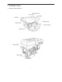
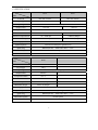
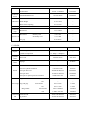
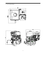
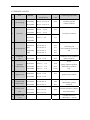
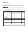
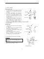
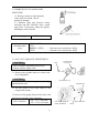
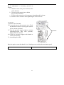
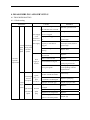
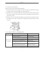
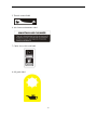
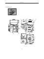
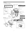
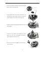
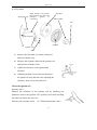
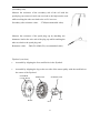
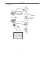
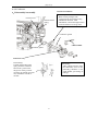
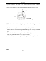
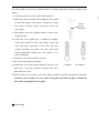
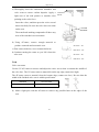
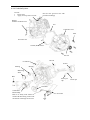
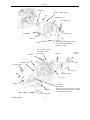
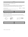
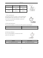
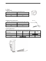
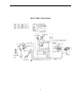
GASOLINE ENGINE
R80-R440 HORIZONTAL SHAFT
SERVICE MANUAL
CHONGQING RATO POWER
MANUFACTURING CORPORATION
This manual contains information about how to perform routine maintenance and how to do
troubleshooting.
Keep this manual handy, so you can refer to it at any time.
This service manual describes correct methods for maintaining this equipment. If any
personal casualty or equipment damage is caused due to disregard of our rules, our company
does not assume any responsibility.
NOTICE:
Copyright is reserved, and no part of this publication may be reproduced without RATO
Company’s written permission.
SAFETY MESSAGES
Your safety and the safety of others are very important. We have provided important safety
messages in this manual and on the generator. Please read these messages carefully.
A safety message alerts you to potential hazards that could injure you or others. Each safety
and one of three words: DANGER,
message is preceded by a safety alert symbol
WARNING, or CAUTION. These messages mean:
You WILL be KILLED or SERIOUSLY INJURED if you don’t follow
instructions.
You CAN be KILLED or SERIOUSLY INJURED if you don’t follow
instructions.
You CAN be INJURED if you don’t follow instructions.
Your generator or other property could be damaged if you don’t
follow instructions.
CONTENTS
1. INTRODUCTION ·············································································································· 1 1-1 PARTS DESCRIPTION····························································································· 1 1-2 SPECIFICATION ······································································································ 2 1-3 SERVICE LIMIT ······································································································· 3 2. DIMENSIONS AND TORQUE ·························································································· 6 2-1 ENGINE DIMENSIONS ··························································································· 6 2-1-1 R100 ······················································································································· 6 2-1-2 R80/R160/R180/R200/R210/R225 ·································································· 7 2-1-3 R270/R280/R300 ····························································································· 8 2-1-4 R390/R420/R440 ····························································································· 9 2-2 TORQUE VALUES ································································································· 10 2-3 STANDARD Torque valueS ···················································································· 12 3. MAINTENANCE ············································································································· 13 3-1. Maintenance schedule ····························································································· 13 3-2 engine oil ················································································································· 14 3-3 Air cleaner ··············································································································· 15 3-4 Cleaning of the fuel filter ························································································· 15 3-5 spark plug cleaning and adjusting ············································································ 16 3-6 valve clearance adjustment ······················································································ 16 3-7 governor··················································································································· 17 4. DISASSEMBLING AND SERVICING ··········································································· 18 4-1 Troubleshooting ······································································································· 18 4-1-1 Hard starting ·································································································· 18 4-1-2 Engine lacks power························································································ 20 4-1-3 Speed is unstable ··························································································· 21 4-1-4 Motor is unable to start ·················································································· 21 4-1-5 Exhaust gas color is abnormal ······································································· 22 4-1-6 Unable to ignite ····························································································· 22 4-1-7 Oil alert system malfunction ·········································································· 23 4-1-8 GASOLINE ENGINE IS OVERERHEATED ··············································· 23 4-2 Preparation of servicing ··························································································· 24 4-2-1 Safety precautions ························································································· 24
4-2-2 Special tools ·································································································· 28 4-3 DISASSEMBLING chart ························································································ 29
4-4 Engine······················································································································ 30 4-4-1 Recoil starter·································································································· 31 4-4-2 Flywheel ········································································································ 33 4-4-3 Air cleaner ····································································································· 35 4-4-4 Carburetor······································································································ 37 4-4-5 Cylinder head /valve ······················································································ 40 4-4-6 Crankshaft/piston ··························································································· 46 4-4-7 Starting control box ······················································································· 55 1. INTRODUCTION
1-1 PARTS DESCRIPTION
Fuel tank cover
Air cleaner
Fuel tank
Muffler
Throttle grip
Spark plug
Recoil starter
Choke lever
Start handle
Drain plug
Oil dipstick
1
1-2 SPECIFICATION
Model
R210
R225
L×W×H
390×320×345mm
390×320×345mm
Dry Weight
16.5 kg
16.5kg
items
Engine Type
Displacement
4-stroke, OHV, single cylinder
212 cm3
223cm3
Compression Ratio
8.5±0.3
Bore×Stroke
70×55 mm
70×58mm
Maximum Output Power
4.2/3600 rpm
4.4kW/3,600rpm
Maximum Torque
12N·m/2500rpm
13N·m/2,500rpm
Cooling System
Forced Air-cooled
Ignition System
Transistorized Magneto Ignition(TCI)
Spark Plug
BPR6ES(NGK),NHSP LD F7RTC,F7TC
Lubrication System
Forced Splash
PTO Shaft Rotation
Counterclockwise
Model
items
R420
L×W×H
465×415×440mm
Dry Weight
28kg
Engine Type
4-stroke, OHV, single cylinder
Displacement
420cm3
Compression Ratio
8.5:1
Bore×Stroke
90×66mm
Maximum Output Power
8.5kW/3,600rpm
Maximum Torque
25N·m /2,500rpm
Cooling System
Forced Air-cooled
Ignition System
Transistorized Magneto Ignition(TCI)
Spark Plug
BPR6ES(NGK),NHSP LD F7RTC,F7TC
Lubrication System
Forced Splash
PTO Shaft Rotation
Counterclockwise
2
1-3 SERVICE LIMIT
1-3-1 R210
Parts
Item
Standard Value
Gasoline
Engine
Maximum Speed (No Load)
Cylinder
Cylinder Bore I.D.
Cylinder
Head
Warpage
3750-3810rpm
≧1.17Mpa(1400rpm)
Cylinder Compression
70.165mm
--
0.10mm
69.965-69.985 mm
69.845mm
0.015-0.050mm
0.12mm
18 .002-18.008 mm
18.048mm
Piston Pin O.D.
18.0-17.994 mm
17.954mm
Piston Pin-to-Piston Pin Bore Clearance
0.002-0.014mm
0.06mm
Ring Side Clearance:
0.035-0.070mm
0.15mm
--
--
0.2-0.35mm
1.0mm
Oil Ring
0.2-0.7mm
1.0mm
Top /Second/Oil Ring
1.5-1.450 mm
1.37mm
2.5-2.450 mm
2.37mm
18.005-18.020mm
18.07mm
30.020-30.033mm
30.066mm
0.040-0.063mm
0.12mm
0.1-0.7mm
1.1mm
29.970-29.980mm
29.920mm
IN
0.15±0.02mm
--
EX
0.20±0.02mm
--
IN
5.468 -5.48mm
5.318mm
EX
5.425 -5.44mm
5.275mm
IN/EX
5.50-5.512 mm
5.572mm
IN
0.02-0.044mm
0.1mm
EX
0.06-0.087mm
0.12mm
0.7-0.9 mm
2.0mm
30.0 mm
28.5mm
27.500-27.900mm
27.450mm
Piston-to-Cylinder Clearance
Piston Pin Bore I.D.
Top /Second Ring
Oil Ring
Piston Rings
Ring End Gap:
Ring Width:
Top /Second Ring
Small End I.D.
Connecting Big End I.D.
Rod
Big End Oil Clearance
Big End Side Clearance
Crankshaft Crankshaft pin O.D
Valve Clearance
Stem O.D
Valve
Guide I.D
Stem-to-Guide Clearance
Seat Width
Spring Free Length
Camshaft
--
70.0-70.015 mm
Skirt O.D.
Piston
Service Limit
Cam Height
IN
3
EX
27.547-7.947mm
27.500mm
13.966 -13.984mm
13.916mm
14-14.018mm
14.048mm
0.85
--
13.7±1.5mm
--
2-1/8 circle
--
Spark Plug Gap
0.7-0.8mm
--
Spark Plug
Resistance
Cap
7.5-12.5kΩ
--
Primary Coil
0.8-1.0Ω
--
Secondary Coil
5.9-7.1kΩ
--
0.4-0.6mm
--
Standard
Service limit
Journal O.D
Crankcase
Cover
Camshaft Holder I.D.
Main Jet
Carburetor Float Height
Pilot Screw Opening
Resistance
Ignition Coil
Air gap
1-3-2 R420
Parts
Engine
Item
Maximum speed (No load)
3750-3850rpm
Cylinder compression
≧1.2Mpa(1400rpm)
Cylinder
Sleeve I.D
head
90-90.015mm
90.17mm
--
0.10mm
Skirt O.D.
89.96-89.97 mm
89.85mm
Piston-to-cylinder clearance
0.03-0.055 mm
0.27mm
Piston pin bore I.D.
20.002-20.008 mm
20.042mm
Piston pin O.D
19.992-19.998 mm
19.950mm
0.004-0.016 mm
0.08mm
0.02-0.06mm
0.15mm
--
--
0.2-0.4 mm
1.0mm
Oil
0.2-0.7 mm
1.0mm
first/second
1.960-1.990mm
1.940mm
Oil
1.960-1.975 mm
1.940mm
20.011-20.022 mm
20.07mm
36.025-30.039 mm
36.07mm
Cylinder
Warpage
head
Piston
--
Piston pin-to-piston pin bore clearance
Ring side clearance: first/ second
Oil
Piston rings Ring end gap:
Ring width:
first/second
Connecting Small end I.D
rod
Big end I.D
4
Big end oil clearance
0.25-0.65 mm
0.12mm
Big end side clearance
0.1-0.4 mm
1.0mm
35.975-35.985 mm
35.92mm
Crankshaft Crankshaft pin O.D
Valve clearance
IN
EX
Stem O.D
IN
0.15±0.020.20±0.02mm
--6.44mm
EX
6.565-6.590 mm
6.4mm
IN/EX
6.535-6.550 mm
6.66mm
IN
6.6-6.615 mm
0010-0.040mm
0.050-0.080mm
0.65-0.95
38.5-39.5mm
0.11mm
0.13mm
IN
32.59mm
32.54mm
EX
32.07
32.02mm
15.966-15.984 mm
15.92mm
Crankcase
Camshaft holder I.D
cover
16.000-16.018
16.050mm
Main jet
Φ1.1
--
13.2±1.5 mm
--
2-1/4
--
Spark plug Gap
0.7-0.8mm
--
Spark plug
Resistance
cap
7.5-12.5kΩ
--
Primary coil
0.6-0.9Ω
--
Secondary coil
5.6-6.9kΩ
--
0.3-0.5mm
--
Valves
Guide I.D
Stem clearance
EX
Seat width
Spring free length
Cam height
camshaft
Journal O.D
Carburetor Float height
Pilot screw opening
Resistance
Ignition coil
Air gap
5
2.0mm
37.5mm
2. DIMENSIONS AND TORQUE
2-1 ENGINE DIMENSIONS
2-1-1 R100/R80
6
2-1-2 R160/R180/R200/R210/R225
7
2-1-3 R270/ R280/R300
8
2-1-4 R390/R420/R440
9
2-2 TORQUE VALUES
Ser.
no.
1
2
Part
Oil drain plug
Oil sensor
Torque
value
Connecting components
R100
Part description and
specifications
M10×1.5×15 8.8-A
R160-R225
M10×1.5×15 8.8-A
22±2
R270-R440
M12×1.5×18 8.8-A
Oil drain plug-flat
washer-crankcase
R100
M6×14
8.8-A
R160-R225
M6×14
8.8-A
R270-R440
M6×16
8.8-A
MODEL
8±2
Oil sensor-crankcase
R100
R160-R225
M10×1.5
8-A
7±1
R100
M6×25 10.9-A
12±1
R160-R210
M7×32 10.9-A
13±1
R225
M5×32 10.9-A
8±1
R270-R420
M8×35 10.9-A
15±1
R440
M8×35 10.9-A
18±1
R100
M6×25 8.8-A
11±2
R160-R420
M8×32 8.8-A
28±2
R100
M12×1.25 8-A
55±4
R160-R225
M14×1.5
8-A
75±4
R270-R300
M16×1.5
8-A
95±4
R390-R440
M16×1.5
8-A
133±4
Starter
pulley-impeller-flywheel
subassembly-crankcase
assy.
R100
M6×20 8.8-A
R160-R225
M6×25 8.8-A
11±1
Ignition coil-crankcase
R270-R440
M6×28 8.8-A
R100
M6×20 10.9-A
32±2
R160-R225
M8×32 10.9-A
30±2
R270-R440
M8×35 10.9-A
40±3
R270-R440
3
4
5
6
7
8
9
Connecting rod
Crankcase
cover
Flywheel
subassembly
Ignition coil
Cylinder head
subassembly
R100
M8×1.25 8.8-A
Rocker shaft
bolt
R160-R225
M8×1.25 8.8-A
R270-R440
M8×1.25 8.8-A
Cylinder head
cover
R100
M6×12 8.8-A
10
Connecting rod
cover-crankcase-connecting
rod
Crankcase cover-crankcase
gasket-crankcase
Cylinder head
subassembly- gasketcrankcase
24±2
Rocker shaft bolt- cylinder
head subassembly
10±1
Cylinder head cover
subassembly - cylinder
subassembly
10
Spark plug
11
Cylinder
shroud
12
13
14
15
16
Lower shield
Oil protector
Shroud
Recoil starter
Air cleaner
Throttle control
17
subassembly
18
19
20
21
Governor
support
subassembly
Charging coil
subassembly
Charging coil
clamp
Starter motor
R160-R225
M6×12 8.8-A
R270-R440
--
R100-R440
M14×1.25
R100
M6×10 8.8-A
R160-R210
M6×8
R270-R4440
M6×12 8.8-A
R100
--
R160-R225
M6×16 8.8-A
R270-R440
--
R100
--
R160-R225
M6×12 8.8-A
R270-R440
M6×12 8.8-A
R100
M6×12 8.8-A
R160-R225
M6×12 8.8-A
R270-R440
M6×12 8.8-A
R100
M6×8
8.8-A
R160-R225
M6×8
8.8-A
R270-R440
M6×8
8.8-A
R100-R440
M6
R100
M6×8
R160-R225
M6×12 8.8-A
R270-R440
M6×12 8.8-A
8.8-A
8-A
head subassembly
30±4
Spark plug-cylinder head
subassembly
10±2
Cylinder shroud-cylinder
head subassembly
10±2
Lower shield- crankcase
8±2
Oil protector - crankcase
10±2
Shroud- crankcase
10±2
Recoil starter- shroud
10±2
Air cleaner- gasketcarburetor
10±2
Throttle control
subassembly- crankcase cylinder head subassembly
8±1
Governor support
subassembly - Governor
arm- governor support
subassembly
10±2
Charging coil subassembly
- crankcase
10±2
Charging coil clamp crankcase
11±1
Starter motor subassembly -
8.8-A
R100-R400
M6
8-A
R100
--
R160-R225
M6×28 8.8-A
R270-R440
M6×32 8.8-A
R100
--
R160-R225
M6×10 8.8-A
R270-R440
M6×10 8.8-A
R100
-11
subassembly
R160-R225
M6×35 8.8-A
R270-R440
M6×30 8.8-A
crankcase
2-3 STANDARD TORQUE VALUES
Item
Standard
torque
Specifications
Torque valve
N·m
Kg·m
5mm bolt, nut
5.5
0.55
6mm bolt, nut
10
1.0
8mm bolt, nut
21
2.4
10mm bolt, nut
37.5
3.75
12mm bolt, nut
55
5.5
12
3. MAINTENANCE
3-1. MAINTENANCE SCHEDULE
Good maintenance is essential for safe, economical, and trouble-free operation. It will also
help reduce air pollution.
Exhaust gas contains poisonous carbon monoxide. Shut off the
engine before performing any maintenance. If the engine must be
running during maintenance, make sure the area is well ventilated.
Periodic maintenance and adjustment are necessary for keeping the generator in a good
operating condition. Perform the service and inspection at the intervals shown in the
Maintenance Schedule below:
Time
option
Each use
First month
or 20 Hrs.
(3)
Oil
Check
Oil
○
Clean
Spark plug
Clean
300 Hrs.
(3)
○
○
Air cleaner element
Clean
Fuel strainer
Every year or
○
Replace
Air cleaner element
Check
Every 3
Every 6
months or 50 months or 100
Hrs. (3)
Hrs. (3)
○※
○
○
Adjust
Valve gap
Check
○
Adjust
Fuel tank, fuel element
Clean
Fuel tube
○
Every 2 years (2
Check
Replace
Every 4 years (4)
※ Clean the air cleaner once every 10 hours or once every day when engine is used in dusty
areas.
13
3-2 ENGINE OIL
● Oil change
1)Dismount the oil filler cap and oil
Oil dipstick
drain bolt to drain dirty oil.
2)Tighten the oil drain plug
Oil drain plug
See 2-2-1Maintenance Standard
Oil drain hole
3)Add the clean oil from the filler neck.
R100 Oil capacity
0.35L
R160/R180/R200/R210/R225 Oil capacity
0.6L
R270/R300/R390/R420 Oil capacity
1.1L
Recommended oil
General oil: SAE15W-40 SJ class or equivalent API classified
SJ class SAE10W-30 oil.
※In a low temperature range (below 10℃),use oil with the
grade higher than SAE10W-30。
※In a cold environment(temperature is below -15℃), use
SAE5W-30,or equivalent API classified SJ class SAE5W-30
oil.
4)After filling, check oil level. If the oil is insufficient, add the oil to the upper limit.
CAUTION: Run with insufficient engine oil may damage the engine severely.
Upper limit
Lower limit
14
3-3 AIR CLEANER
Dual element type
1) Remove the nut, air cleaner cover and
wing nut. Remove polyurethane and paper
elements.
2) Clean polyurethane with detergent,
then, blow it dry with compressed air or
squeeze it dry. Dip the element in clean
oil, then, forcefully squeeze it dry and
install it back.
3)Tap the element lightly several times on
a hard surface to remove excess dirt or
blow compressed air lightly from the
inside out. If it is dirty, replace it in time.
Nut
Air cleaner
cover
Polyurethane
element
Wing nut
Paper element
CAUTION: Polyurethane element containing too much oil will jam
the strainer holes.
Oil bath type
1)Clean the air cleaner case with cleaning
oil and dry it.
2)Add the clean oil to specified level and
install the air cleaner case back.
3)Clean the polyurethane element with
cleaning oil, then
blow with compressed air or squeeze.
Dip the element in clean oil, then,
forcefully squeeze and install it back.
Nut
Air cleaner
case cover
Seal ring
Polyurethane
element
Air cleaner case
O-ring
3-4 CLEANING OF THE FUEL FILTER
Caution
· Don’t smoke when washing.
· Be sure there is no fuel leakage after
tightening.
Turn the fuel cock to OFF position and
tighten filter cup. Torque:7N.m
OFF
Fuel strainer cup
15
3-5 SPARK PLUG CLEANING AND
ADJUSTING
1)Remove carbon or other deposits
with a stiff wire brush. Check
gasket for damage.
2 ) Measure plug gap between center
electrode and side electrode with a spark
plug feeler. If necessary, adjust the gap by
bending the side electrode.
Spark plug gap
Standard spark
plug
0.7 - 0.8 mm
BP6ES(NGK)
F7TC
BPR6ES(NGK) ……with anti-wave interference ability
F7RTC …………….…with anti-wave interference ability
3-6 VALVE CLEARANCE ADJUSTMENT
Bolt
CAUTION:
Valve clearance adjustment must be per
formed with the engine cold.
Cylinder head
cover gasket
1) Remove the cylinder head cover bolt, head
cover and gasket.
CAUTION:
Be careful to avoid oil leaking when removing
cylinder head cover.
Cylinder head cover
Valve
Rocker arm
2) Set the piston at top dead center of the
compression stroke.
3)Insert a feeler gauge between the rocker arm
and valve to measure valve clearance.
IN:0.15 ± 0.02 mm
Valve clearance
EX:0.20 ± 0.02 mm
16
Valve lock nut
Use feeler gauge to
Valve
check clearance.
4 ) If adjustment is necessary, proceed as
follows:
a.Hold the rocker arm pivot and loosen the
valve lock nut
b.Turn the rocker arm pivot to obtain
the specified clearance.
c.Fix the rocker arm pivot with a spanner, then tighten the lock nut.
d.Recheck valve clearance after tightening the valve lock nut.
3-7 governor
1)Remove the fuel tank.
2)Loosen the nut on the governor arm. Check
the throttle to ensure it is fully open.(turn to
left to extreme position).
3)Turn the governor support right to extreme
position(governor fully close position).
Tighten the bolt and nut.
4)Check the governor support and throttle to
ensure free moving.
5)Assembling fuel tank.
ClockWise
Start the engine, rotate the throttle lever l1miting screw to adjust the maximum speed.
Maximum
3780±50rpm
17
4. DISASSEMBLING AND SERVICING
4-1 TROUBLESHOOTING
4-1-1 Hard starting
TROUBLE
CAUSE
REMEDY
There is no enough fuel in fuel
Add fuel, open fuel cock.
tank and fuel cock is closed.
Normal Something
spark wrong with
plug
the fuel
spark
system.
Normal
cylinder
compression
Air vent in the fuel tank
Fuel supply cover is clogged
is not
Improper or clogged main
smooth or jet.
there is no Needle valve is not closed
fuel supply. properly or start hole is
clogged.
Fuel
supply is
normal.
al fuel
supply
system.
Spark
Normal high
plug is in
–tension
poor
cord spark.
conditions
High-tension
cord with no
spark
Normal
spark
plug
Unclog air vent.
Readjust or clean, blow to
get through.
Dismantle needle valve
and repair, clean, blow to
get through.
Float is damaged or
sticking.
Repair float
Fuel is too filthy or
deteriorated
Replace
There is water in fuel.
Replace
Too much fuel in engine
Drain extra fuel, dry up
spark plug electrodes.
Wrong fuel grade
Select proper fuel grade
corresponding with the
requirements.
Too much carbon deposit
and dirt around electrodes.
Clear away.
Electrodes are burned badly
or insulators are damaged.
Replace spark plug.
Improper electrode gap.
Adjust to proper value.
High –tension cord is
damaged.
Replace
Ignition coil is damaged.
Replace
Magneto loses magnetism.
Replace
Abnormal gap between the
ignition coil and flywheel.
Adjust gap
18
TROUBLE
CAUSE
REMEDY
Piston ring is worn too much
Replace
or even over its service limit
Piston ring is broken.
Replace
Piston ring is sticking.
Clear up carbon fouling.
Abnormal Normal
Normal Spark plug is not installed
Tighten with a gasket in.
cylinder
fuel
ignition tightly or is installed without a
compression supply
Check cylinder gasket, and the flatness of
system gasket.
system
the surface by which cylinder block
Air leakage between cylinder
contacting with cylinder head
block and cylinder head.
Tighten cylinder head cover bolts in
stipulated order to stipulated torque value.
Air leakage in the valves
Check valve clearance and tightness, repair
if necessary.
If engine still can’t start, take the engine to our authorized dealer to repair it.
z
Spark plug testing
WARNING:
●
When testing the spark plug, never hold the high- tension cord of the spark plug with wet
hand.
●
Make sure there is no spilled fuel outside the engine and that the spark plug isn’t dipped with
fuel.
●
To prevent fire, keep sparks far away from the spark plug mounting hole.
y
Turn the fuel cock to “OFF” position, and drain the gasoline of the carburetor.
y
Remove the spark plug and spark plug cap.
y
Pull the recoil start handle to drive off the gas out of the cylinder.
y
Install the spark plug cap.
y
Put the control lever to “low” position.
19
y
Put negative pole (thread) of the spark plug through cylinder cover to connect to ground and
pull the recoil start handle to observe the spark.
4-1-2 Engine lacks power
TROUBLE
CAUSE
Ignition
system
When increasing
throttle opening,
speed increases
slowly or even
decreases and stops
running
REMEDY
Air in fuel line or fuel line is
clogged
Drain air or unclog fuel line
Main jet is not adjusted properly
Readjust
In carburetor, needle valve and
main jet are clogged.
Clean and blow to get through
Fuel supply Fuel cock is clogged.
system Too much carbon deposit in
combusting chamber.
Clean, replace damaged part
Clear away
Air cleaner is clogged.
Clean air cleaner filter element
Intake pipe is leaking
Repair or replace
Intake pipe is leaking
Repair or replace
Piston, cylinder or piston ring is
worn
Replace the worn part
Poor
Air leakage from the surface along
compression which cylinder block contacts with Replace cylinder gasket
cylinder head.
Too big or too small valve
clearance.
Readjust
z
Compression pressure check
y
Drain the oil of the fuel tank.
y
Drain the gasoline by loosening the fuel drain plug
y
of the carburetor.
y
Remove the spark plug cap and spark plug and install the cylinder pressure meter.
y
Forcibly pull the recoil starter several times and measure compression force(≥0.4MPa)
Cylinder
pressure
meter
20
[键入文字]
4-1-3 Speed is unstable
TROUBLE
Knocking sound
CAUSE
REMEDY
Piston, cylinder or piston ring is worn
excessively.
Replace the worn part
Piston pin and piston pin hole are worn
excessively.
Replace piston or piston pin
Connecting rod small head is worn
excessively.
Replace connecting rod
Roller bearing for crankshaft main journal is
Replace roller bearing
worn.
Engine is too hot
Shoot trouble
Too much carbon deposit in combustion
Abnormal combustion chamber
Lack of spark
Clear away
Improper gasoline grade or low gasoline
quality
Replace with qualified gasoline
There is water in float chamber
Clean
Improper clearance between spark plug and
Adjust
electrodes
Something wrong with induced coil, and so
Check and replace damaged parts
on
4-1-4 Motor is unable to start
TROUBLE
CAUSE
REMEDY
1.Check the battery
Improper connection
connection
2. Check battery
Correct the connection
Wrong gasoline engine, or battery is charged
Check or replace rectification circuit,
insufficiently, battery is stored long without
charge the battery with a special
being used, and pole plate’s sulphation is
charger or replace the battery.
eroded.
Check and eliminate starting
3. Starter motor
Motor and relay are in trouble, connection is
appliance circuit trouble or replace
running is abnormal loose, falling off and switch is damaged.
damaged part.
21
4-1-5 Exhaust gas color is abnormal
TROUBLE
Black smoke
CAUSE
REMEDY
Piston, cylinder or piston ring is worn
excessively.
Replace the worn part
Too much carbon deposit in combustion
chamber
Clear away
Too much carbon deposit in combustion
chamber
Clear away
Improper gasoline grade or low gasoline
quality
Replace with qualified gasoline
Air cleaner is clogged.
Clean air cleaner filter element
4-1-6 Unable to ignite
TROUBLE
CAUSE
Fuel supply
system
Unable to ignite
REMEDY
Fuel has run out
Add fuel
Carburetor is clogged
Check fuel line and unclog it
Float is leaking
Repair
Needle valve is stuck
Dismantle float chamber and
eliminate the sticking
Spark plug is punctured, or
short-circuited by carbon
deposit
Replace spark plug
Side electrode of spark plug
has dropped out
Replace spark plug
Ignition system High-tension cord has
dropped out
Others
Weld it on
Ignition coil is punctured or
short-circuited
Replace ignition coil
Stop engine wire is located
on engine body
Find out the meeting position,
separate them and insulate
Cylinder is seriously scored
and valves have dropped out
Repair or replace damaged parts
22
[键入文字]
4-1-7 Oil alert system malfunction
Check the oil alert system with the following method:
1) Disconnect yellow lead of the engine and connect the engine to ground when the engine
is running. Be sure the alert lamp lights up, and the engine stops.
2) Disconnect oil level switch lead under the specified condition with the engine stopped,
and check the continuity of the yellow and green leads, uncontinuity between yellow and
green leads is normal.
3) Disconnect oil level switch lead after draining oil out with the engine stopped, and check
the continuity of the yellow and green leads, continuity between yellow and green leads
is normal.
4-1-8 GASOLINE ENGINE IS OVERERHEATED
TROUBLE
Gasoline engine is
overheated
CAUSE
REMEDY
Oil insufficient or wrong oil/gasoline ratio
Add engine oil
Exhaust pipe is blocked
Clean exhaust pipe
Shroud is leaking
Repair damaged part
Cooling fins are blocked by foreign matter
Clear cooling fins
Cooling fan is loose and malfunctioning
Reinstall it well
Connecting rod deformation to make piston
and cylinder bushing side wear
Replace connecting rod
Cylinder, piston or piston ring is worn, causing
Replace the worn parts
hunting between cylinder and crankcase
Improper adjustment of engine governor cause Readjust engine governor
23
high speed.
Crankshaft main bearing is burnt out
Replace main bearing
4-2 PREPARATION OF SERVICING
4-2-1 Safety precautions
WARNING:
Indicate the possibility of invalid warranty and personal injury or equipment damage if
instructions are not followed.
Please pay special attention to the following:
1. Strictly set the engine according to the regulated power on the nameplate. Do not
overload, overrun the engine or run it with a low load and at low speed for a long time.
2.
Use prescribed grade of gas and diesel. The fuel should be fully deposited and filtered
before being used. Keep the fuel filler clean, change the fuel periodically.
3.
Periodically check the installation, connection and the degree of tightness of the fixed
bolt. Tighten it if necessary.
4.
Periodically clean the element of the air cleaner, change it when necessary.
5.
The engine is air-cooled, so clean the radiator, wind cover and fan in time in order to
ensure the engine can cool normally.
6.
The operator should be familiar with the working principle and structure of the gasoline
engine, know how to make an emergency stop and the operation of all controlling parts.
Any one without training is forbidden to operate the engine. Keep periodical
maintenance. Solve problems in time. Do not run the engine when it has malfunction.
7.
Run the engine in a well-ventilated place, keep it at least one meter away from building
walls or other equipment, keep away from inflammables such as gasoline, matches and
so on to avoid possibility of fire.
8.
Refuel in a well-ventilated area with the engine stopped, and in places refueling or
storing gasoline, no smoking and any flames or sparks.
9.
Refuel the fuel tank not too much so as to avoid fuel’s spilling out. If there is spilled fuel
around, be sure to clean it thoroughly before starting.
10. Do not run the engine in airtight or poorly ventilated places.
11. The exhaust muffler is very hot during running the engine even after the engine stops.
Never touch it, or you may get burns. Transport or store the engine with it cooled down
entirely.
24
[键入文字]
12. Safety warning labels:
13. Please carefully read warning labels before operating. Our company will not assume any
responsibility, for person injury, or equipment damage caused by disregarding warning
labels.
(Applique labels are shown as follows)
1. Fuel label
2. Warning label
3. Displacement label
4. Trademark label
25
5. Throttle control label
6. Air cleaner maintenance label
7. Choke lever, fuel cock label
8. Oil grade label
26
[键入文字]
9. Oil filling label
27
4-2-2 Special tools
Tool name
Application note
1. Float level gauge
Carburetor float level inspection.
2. Valve guide driver
Valve guide removal, installation.
3. Retainer assembler
Assembling ball bearing.
4. Assembler handle
Installing handle and bearing.
5. Inner retainer assembler
Assembling ball bearing and time gear.
6. Diamond lap 450
Reconditioning valve seat surface.
7. Diamond lap 320
Reconditioning valve seat surface.
8. Flywheel driver
Detaching flywheel.
9. Bearing extractor
Detaching flywheel.
10. Valve guide reamer
Fine reaming the guide inner hole.
28
[键入文字]
4-3 DISASSEMBLING CHART
Engine
Carburetor
Flywheel
Starter motor
Air cleaner
Shroud
Recoil starter
29
4-4 ENGINE
a. Disassembly, reassembly
Fan cover (only used for automatic starter)
Disassembly, reassembly:
Disassemble and reassemble with the recoil
starter assembled.
Control box (only
used for automatic
starter)
Lead support (2)
Assembling: Insert it into fan cover
Ignition coil lead (black)
Engine switch
Starter relay lead
Disassembly:
Detach the clip with
a screwdriver
White lead
Oil level switch lead
(yellow)
Oil level switch lead
(green)
(to side plate)
Black lead
(to ignition coil
lead)
Charging coil lead (white)
Black/red lead
To ignition coil lead
Black lead
(Connect to ignition
coil lead)
Yellow lead
Engine switch
(Engine equipped with oil alert device)
Fan cover (Recoil starter)
Connect to oil level
switch yellow lead
Yellow lead
Connect to oil
level switch)
Black/white lead
Connect to starter
lead
Gray lead
Connect to charging
coil lead
●Lead harness method (only used for engine
with a starter After connecting leads, fix
them with zipper jacket, cable with collar,
and clip as shown as following
Cable with collar
Clip
Zipper jacket
30
[键入文字]
4-4-1 Recoil starter
Guide tray screw
Driving guide
Spring
Drive cam
Starter coil spring
Returning spring
Starter reel
NOTICE:
Wear gloves and eye protection during disassembling, and take care not to allow the
return spring to come out
① Insert the recoil starter rope through the groove in the recoil
starter reel and make a figure-eight knot at the rope end
②
Hang the side hook of the recoil starter spring to the
groove of the recoil starter case, set the recoil starter
spring into the case while counterclockwise rotating
starter spring
31
③. Set the recoil starter coil spring’s outside hook to the
groove of the recoil starter reel.
Groove
Groove
④. Set the starter drive cam on the recoil starter reel,
and install the return spring on the recoil starter reel
while hooking it to the side of the driving cam.
⑤. Install the spring, driving guide and fixing screw one
after another
⑥. Insert the recoil starter rope through the recoil
starter case and recoil start handle, and make a
figure-eight knot at the rope end.
⑦. Pull the recoil starter rope lightly to check the drive
cam’s function.
32
[键入文字]
4-4-2 Flywheel
Spark plug cap
High tension cord (check
the insulation for chap and
damage)
replace
if
necessary)
Flywheel
Starter pulley
Nut
Igniter stop wire
Impeller
Ignition coil
Bolt
a) Remove the fuel tank, air cleaner, carburetor
and recoil starter assy.
b) Measure the clearance between the ignition coil
and flywheel with the feeler.
c) Adjust the clearance of the ignition and
flywheel.
d) Adjusting method: Loosen the bolt and move
the ignition coil up and down for adjusting the
clearance, then, screw down the bolt.
Check the ignition coil
(Primary side)
Measure the resistance of the primary coil by attaching one
ohmmeter lead to the ignition coil’s primary lead while touching
the other test lead to the iron core.
Primary side resistance value:1.0-1.5Ω(recommended value)
33
(Secondary side)
Measure the resistance of the secondary side of the coil with the
spark plug cap removed, touch one test lead to the high tension cord
while touching the other test lead to the coil’s iron core.
Secondary side resistance value: 5-7kΩ(recommended value)
Measure the resistance of the spark plug cap by attaching one
ohmmeter lead to the wire end of the plug cap while touching the
other test lead to the spark plug end.
Resistance value: 5kΩ±5%/10kΩ±5%( recommended value)
Flywheel (cast iron)
y
Assemble by aligning the four small holes in the flywheel.
y
Assemble by aligning the lug on the rear side of the starter pulley with the small hole at
the center of the flywheel.
FLYWHHL
(CAST IRON)
HOLE
STARTER CUP
IMPELLER
LUG
34
NUT
[键入文字]
4-4-3 Air cleaner
Wing nut
Air cleaner cover
Reassembly: after
reassembling the
element and grid into
the cover, install the
cover to the body
Air cleaner element
Elbow seal
Noise silencer (only
for silence)
Collar B
Air cleaner elbow
Disassembly/reassembly:
·remove and install with
the choke lever and fuel
valve in the ON position
·Clean the inside of the
elbow with compressed
air before installation.
35
Air cleaner
element
(polyurethane)
Air cleaner
element
(paper)
Oil bath type
Wing nut
Air cleaner cover
Air cleaner element
(polyurethane)
Air cleaner grid
Air cleaner case
Oil capacity: 60cc
Reassembly:
After
cleaning
with
solvent, fill with clean oil
and install
Collar
Elbow packing
Air cleaner elbow
Disassembly/reassembly:
·Remove and install with the
choke lever in “ON” position
and fuel cock in “OFF” position.
·Clean the inside of the elbow
with compressed air before
installation.
36
[键入文字]
4-4-4 Carburetor
Carburetor insulator
a.Disassembly/reassembly
Governor rod
Throttle return
spring
Reassembly:
Blow out the passages with
compressed air and install, noting
installation direction. After
installation, connect the high tension
cord and fuel hose to the ground.
Carburetor gasket
Choke handle
Insulator gasket
Carburetor assy.
Disassembly:
Unhook the throttle return
spring. Pull the carburetor
forward to a point where
the groove in the governor
rod lines up with the governor
rod, and lift the rod out of
its hole.
Reassembly:
After pulling fuel hose from
the carburetor, insert it into
protruding shoulder of the
choke handle, preventing oil
leakage.
37
b.Disassembly/reassembly
CAUTION
·Remove the drain plug and drain the carburetor before disassembling
·Prohibit fire.
Idle speed mixed ratio
adjusting screw
reassembly:
Inspect for wear before
installation.
Choke lever
Fuel cock
Idle speed adjusting
screw
Float spring
Main nozzle
Reassembly:
Clean thoroughly with
compressed air before
installation.
Reassembly:
Check for top wear or
spring wear before
installation.
Main jet
Reassembly:Clean passage
thoroughly with compressed
air before installation
Main jet :P.2—4
Filling oil
needle
valve
Float pin
Float
Reassembly:
Check the moving by
finger after installation.
Oil cup bolt
CAUTION
Oil cup drain bolt
After assembly, check for any
sign of fuel leakage.
38
[键入文字]
Inspection
●Float level height
Place the carburetor in the position as shown and push the float in by finger and measure the
distance between the float top and carburetor body (float height).
Specified float height
See 1-3Maintenance Standard
If the float height is out of specification, replace the float valve and recheck the float height
Float level gauge
39
4-4-5 Cylinder head /valve
1) Removal/ installation
① Remove the fuel tank
② Remove the air cleaner
③ Remove the recoil starter and shroud
Spark plug: Clean and
adjust spark plug before
installation
④ Remove the carburetor and insulator
Stud
EX valve guide
Cylinder
head
gasket
Cylinder head
cover gasket
Pin
Cylinder head cover
Stud
IN valve guide
Guide circlip
Apply oil to thread.
Loosen and tighten the bolts in a
crisscross pattern, especially
when tightening, all bolts should
be tightened gradually and evenly
up to specified torque.
Bolt
Assembly /disassembly:
Loosen and tighten the bolts
in a crisscross pattern in 2 or
3 steps.
Breather tube
Exhaust valve
Retainer
Spring
Guide seal
Reassembly:
Before installation, remove
carbon deposits and inspect
the valve.
Valve rotator
Valve adjusting
bolt
Valve adjusting nut
Lifter
Valve lock nut
Valve rocker
Reassembly: Before
installing check for
wear
on
the
surfaces
which
contact the valve
adjusting bolt, the
push rod and the
Valve tappet
Reassembly:
Check
both
Lifter stopper ends for wear
plate assembly and the rod for
straightness.
Be sure the rod
ends are firmly
seated in the
lifters.
40
Intake valve
Reassembly:
Don’t interchange with the
exhaust valve.
Be careful not to damage the
valve stem when installing.
Cylinder head
Installation:
Before installation, remove
any carbon deposits from the
combustion chamber and
inspect the valve seats.
Measure the cylinder
compression after reassembly
[键入文字]
Valve spring retainer:
Push down on the valve spring and move the retainer to the side so that valve stem slips
through the side hole
Do not remove the valve spring retainers while the cylinder head is installed to the cylinder,
or the valves will drop into the cylinder.
2)Inspect/service/repair:
① Valve stem outside diameter
Inspect the valve stem outside diameter with the micrometer, if it is found out of the standard
or service limit, or if it has visible burn and damage on the valve face, please replace it with
new one.
Standard
e vice limit
See 1-3Maintenance Standard
See 1-3Maintenance Standard
② Valve spring free length
Measure the free length of the valve
Springs: If out of the standard or service
limit; please replace the spring
Standard
Service limit
See 1-3Maintenance Standard
See 1-3Maintenance Standard
③ Valve guide
41
Inspect:
a) Inspect the valve guide for smoothness, scratch and damage in the inner surface, and
matching between the valve guide and cylinder cover for fastness.
VALVE
GUIDE
REAMER
b) Use the valve guide reamer, ream
the valve guides to remove any carbon
deposits before measuring.
If the valve guide inside diameter is lower than standard or out of the service limit, replace
the guide.
Standard
Service limit
See 1-3Maintenance Standard
See 1-3Maintenance Standard
VALVE GUIDE
DRIVER
Replacement:
42
[键入文字]
a) Chill the replacement valve guides in the freezer section of a refrigerator for about an
hour.
b) Drive the valve guide out of the combustion chamber side using valve guide driver.
VALVE GUIDE
DRIVER
CLIP
Valve guide
Installation height
NOTICE: Be careful to avoid damaging the cylinder head when driving out the valve
guides.
c) Install the new valve guides from the valve spring side of the cylinder head.
Exhaust side: Drive the exhaust valve guide until the clip is fully seated (as shown in the
fig.)
Intake side: Drive the intake valve guide to the specified height (measured from the top
of the valve guide to the cylinder cover as shown in the fig.)
d)
After installation, inspect the valve guide for damage, if it is damaged, please replace.
Reamer:
43
For best results, be sure the cylinder head is at room temperature before reaming valve
guides.
a) Coat the reamer and valve guide with cutting oil.
V
R
b) Rotate the reamer clockwise through the valve guide
for the full length of the reamer. Continue to rotate
VALVE
GUIDE
REAMER
the reamer clockwise while removing it from the
valve guide.
c) Thoroughly clean the cylinder head to remove any
cutting residue.
d) Check the valve guide bore, it should be straight,
round and centered in the valve guide, insert the
valve and check operation. If the valve does not
operate smoothly, the guide may have been bent
during installation. Replace the valve guide if it is
bent or damaged.
e) Check the valve stem-to-guide clearance
f) The valve stem-to-guide clearance:
g) Deduct the valve stem outside diameter from the vale
CORRECT
INCORRECT
guide bore to get the clearance between the valve
guide and valve stem.
h) If the clearance is over the service limit, judge whether new guide can make the clearance
conform to service limit, if it can, replace the guide and ream the guide, refinish the
valve when replacing the valve guide.
④ Valve seat:
44
[键入文字]
a) Thoroughly clean the combustion chambers and
valve seats to remove carbon deposits. Apply a VALVE
light coat of red lead powder or erasable color
FACE
painting to the valve faces.
Insert the valves, and then press the valve several
times forcefully. Be sure the valve does not rotate
CUTTER
HOLDER
on the seat.
The transferred marking compound will show any
area of the seat that is not concentric.
b) Using 45°cutter, remove enough material to
produce a smooth and concentric seat.
IN valve:32°
c) Turn cutter clockwise, never counterclockwise.
d) Continue turning the cutter as you lift it from the
EN valve:32°
IN valve:45°
valve seat.
EX valve:45°
Tool:
Valve seat cutter
Use the 32°-45°cutters to narrow and adjust the valve seat so that it contacts the middle of
the valve face. The 32°cutter removes material from the top edge (contact too high).
The 45°cutter removes material from the bottom edge (contact too low). Be sure that the
width of the finished valve seat is within specification.
Standard
Service limit
See 1-3Maintenance Standard
See 1-3Maintenance Standard
d) Make a light pass with the 45°cutter to remove any possible burrs at the edges of the
seat.
45
4-4-6 Crankshaft/piston
Oil seal
y
Don’t reuse
y
Apply oil to lip of the oil seal
Pin(Fix the governor arm with
pin after installing)
Washer
Install it inside the seat.
Pin
Crankcase cover
Bolt
Governor arm
Gasket (Don’t reuse)
Oil seal
Oil seal
Crankcase
Piston
Bearing
Bearing
Balancing
shaft
Bolt
Piston pin
clip
Camshaft
Crankshaft:
Reassembly:
Push it in firmly until contact is
made with the bearing surface. Be
careful not to damage the oil seal
Oil sensor
Bolt
46
Piston pin
[键入文字]
Bearing
gasket(Don’t reuse)
Pin
Crankcase cover
Oil filter cap
Oil dipstick
Sealing ring
Seal ring
Oil seal
(Don’t damage the edge of the
oil seal when reassembling
crankcase cover )
Bolt
Spacer
Governor arm
Governor gear
Pin(Fix the governor
arm with pin after
installing)
Piston
pin clip
Oil seal
Nut
Piston
Piston pin
Bolt
Connection rod
Crankcase
Rod cap
Camshaft
Bolt
Oil sensor
①Disassembly:
47
Crankshaft:
Reassembly:
Push in firmly until contact is made
with the bearing surface. Be careful
not to damage the oil seal
a) Piston
• Install with the marker marking facing upward as shown.
• Do not interchange the first ring and the second ring (first ring is chrome plated)
• After assembly, check for smooth movement of the piston rings.
• Stagger the piston ring end gaps 120° apart.
②Reassembly:
a) Piston pin clip
Install by setting front end of the clip in the piston
groove, holding the other end with long nosed
pliers, and rotating the clip in.
Do not align the end gap of the clip with the
cutout in the
piston pin bore.
c) Connecting rod cap
Install by aligning the alignment marks on the connecting rod cap.
Alignment marks
② Piston check
48
[键入文字]
Check the piston and cylinder for contacting, and check the groove for defects, piston top for
burn and cracks. If any of them is damaged, replace it.
Clean the carbon deposit
Clean the deposit round the piston top and cylinder neck before checking, first soak the
carbon deposit with kerosene, then clean with a metal scraper or metal brush.
a) Piston skirt O.D
Measure the piston skirt O.D with an outside micrometer, if it is
out of the service limit, replace it.
Standard
Service limit
See 1-3Maintenance Standard
See 1-3Maintenance Standard
b) Piston pin bore to piston clearance
Separately measure the piston pin bore I.D and O.D with inside micrometer and outside
micrometer. Then calculate clearance by measuring results. If out of the service limit, replace
the piston pin and piston as necessary.
Standard
Service limit
See 1-3Maintenance Standard
See 1-3Maintenance Standard
c) Piston-to-cylinder clearance
49
Difference between cylinder maximum diameter and piston skirt should be considered as
piston-to-cylinder clearance.
NOTICE: This clearance must be checked before and after repairing.
Check with piston upside down in the cylinder, and inserting feeler between piston skirt
bearing face and wall, then pull the feeler out, if feeling resistance and moving smoothly out,
the thickness of the feeler shall be considered as piston-to-cylinder clearance.
Standard
Service limit
See 1-3Maintenance Standard
See 1-3Maintenance Standard
d) Piston ring side clearance
Check by placing each ring into its groove. The piston ring should be
freely turned without loosening and sticking. Then measure by
inserting the feeler into clearance of the ring and upper and lower face.
Standard
Service limit
See 1-3Maintenance Standard
See 1-3Maintenance Standard
e) Piston ring end gap
Flatly place the piston into the cylinder by pushing the piston head to working position.
Measure the opening clearance with a feeler, that clearance should not be too big or too small,
if it is too big can, cylinder sealing performance will be poor, if it is too small, piston
expanded by heat will be blocked in the cylinder, thus causing piston broken and “sticking”.
If opening clearance is too small, file the opening with fine flat file. Often check in the
cylinder when filing until the proper clearance is got.
50
[键入文字]
First ring/second ring
Oil ring
Standard
Service limit
See 1-3Maintenance
See 1-3Maintenance
Standard
Standard
See 1-3Maintenance
See 1-3Maintenance
Standard
Standard
Piston ring
③ Check connecting rod
If connecting rod is bent or twisted, or its big end shaft hole
and small end hole have apparent grooves, or have cracks
on one side, the connecting rod should be rejected and
replaced with a new one.
a) Check small end diameter
If it is out of the standard or exceeds service limit, replace the connecting rod.
Standard
Service limit
See 1-3Maintenance Standard
See 1-3Maintenance Standard
b) Check big end diameter
If it is out of the standard or exceeds service limit,
replace the connecting rod.
Standard
Service limit
See 1-3Maintenance Standard
See 1-3Maintenance Standard
51
c)Connecting rod big end oil clearance
y Wipe oil off the crank pin and connecting rod bearing
mating surface.
y Set the plastic gauge on the crank pin, then install
connecting rod and fasten bolts to specified torque.
Torque:See 1-3Maintenance Standard
NOTICE: Place the plastic gauge axially.
y
Bolt
Remove connecting rod and measure with
plastic gauge.
y
If the clearance exceeds the service limit, replace the connecting rod and recheck the
clearance.
PLASTIC GAUGE
Standard
Service limit
See 1-3Maintenance Standard
See 1-3Maintenance Standard
PLASTIC GAUGE
WITH SCALE
④ Camshaft check
The camshaft is main driving part of the valve timing mechanism,
which controls the intake and exhaust valves’ opening and closing.
Feature: The shaft is equipped with a cam and journal which can
control intake and exhaust. When operating, camshaft operating
face and lifter will be badly rubbed from periodical impact and
will be easily damaged. So, the camshaft shall be wearable and lubricated well.
y
Visually inspect camshaft face and camshaft height for damage, and camshaft and
bearing for loosening and wear, replace if necessary.
y
Check camshaft for height. If it is out of the service limit, replace the camshaft.
52
[键入文字]
y
Standard
Service limit
IN lifter
See 1-3Maintenance Standard
See 1-3Maintenance Standard
EX lifter
See 1-3Maintenance Standard
See 1-3Maintenance Standard
Check outside diameter of the camshaft, if it is less than the service limit, replace the
camshaft.
Standard
Service limit
See 1-3Maintenance Standard
See 1-3Maintenance Standard
Camshaft wearing cause and its influence on engine performance:
Poor lubrication, caused by factors such as low oil viscosity, too many impurities, and
little recycling oil, will result in camshaft abnormal wearing, making it hard for the camshaft
surface to have a complete oil film, causing the camshaft surface seriously worn in the state
of high-speed rubbing; installing precision problem is also a factor that can cause lubrication
problem, when the matching clearance of the camshaft journal and camshaft seat or bearing
is out of the service limit, camshaft rotation precision will lower and contacting with the
relative part will produce deviation to make abnormal wearing.
53
⑥Timing gear
a) Check timing gear for engagement clearance and align marks of the gears on two sides.
Timing gear will be damaged if gear is worn, gear face peels off, and gear teeth are broken.
The engagement clearance is bigger due to gear wearing, the noise is bigger.
If the timing gear is damaged, please replace it with new one.
NOTICE: Please replace the gear with a new set to ensure the engaging face completely
engages in.
Crankshaft and Camshaft Alignment
Alignment marks
Crankshaft gear
Camshaft gear
54
[键入文字]
4-4-7 Starting control box
a. Disassembly/reassembly
(Only for starter)
6×12mm(2)
screw
Silicon rectifier
Check : 7-8
Control box
Blade type fuse (5A)
Reassembly:
Check for burn before installation
Oil alert
Check: P.7-8
Reassembly:
Install by aligning with the hole
of the control plate
Control panel
Box installation bracket
Nut
Switch
Check:
Reassembly:
Install with the tab of the thread aligning
with notch of the control panel.
Resetting button(1A)
Reassembly:
Be careful not to install the left and right side
plate reverse.
Switch
Tab
55
b.Check
● Engine switch
Check the continuity between lead and fan cover.
Switch position
Continuity
ON
No
OFF
Yes
● Engine switch (with oil alert)
Check the continuity between black lead and engine switch.
Switch position
Continuity
ON
No
OFF
Yes
Black lead
● Switch (with starter)
Check continuity between leads when switch is kept at each position.
Lead color
Switch position
OFF
Black/red
(to grounding)
○
○
Black/white
White
○
○
ON
START
Check with fuse connected
56
[键入文字]
● Oil alert lamp
Connect the black and yellow leads to 6V battery or dry
cell, check the alert lamp for lighting up.
Black─━ battery(+)
Yellow─━battery(-)
(Don’t connect the positive
and negative poles wrongly)
Black
Yellow
※ Don’t use the battery with over 6V, if so, bulb will break.
Black /red lead
● Connect the black/red and yellow leads
to 6V battery or dry cell, check whether the
alert lamp lights up.
Black─━ battery(+)
Yellow─━battery(-)
(Don’t connect the positive
and negative poles wrongly)
Yellow lead
※ Don’t use the battery with over 6V, if so, bulb will break.
● Silicon rectifier。0
Check continuity between the two terminals, if it is continuous in the forward direction and
uncontinuous in the reverse direction, it shall be considered as normal.
● Resetting button
Check the two terminals for continuity with resetting button turned to ON position.
57
ELECTRIC DIAGRAM
control box
starter
motor
starter relay
charging
coil
58
[键入文字]
Ch on gq ing Rato Power Manu factu rin g Corp oratio n
Add:No. 99 Jiujiang Road, Shuangfu District, Chongqing China
service hotline:400-681-9981
fox:023-85553450
postcode:402247
URL:www.rato.cc
E-mail: [email protected](consultation customer service)
t@ t
( t
d )
59