1
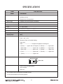
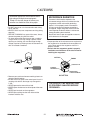
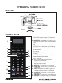
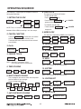
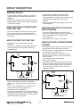
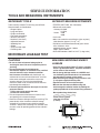
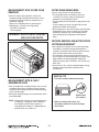
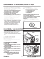
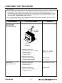
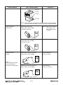
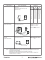
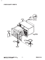
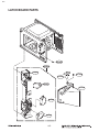
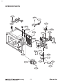
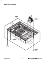
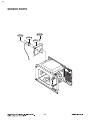
Internal Use Only
Website http://biz.lgservice.com
MICROWAVE OVEN
SERVICE MANUAL
MODEL: LCRT2010ST
CAUTION
BEFORE SERVICING THE UNIT, READ THE SAFETY PRECAUTIONS IN THIS MANUAL.
P/NO : MFL06272518
November, 2010
Printed in Korea
SAFETY PRECAUTIONS
This device is to be serviced only by properly qualified service personnel.
Consult the service manual for proper service procedures to assure continued safety operation and for precautions to be
taken to avoid possible exposure to excessive microwave energy.
PRECAUTIONS TO BE OBSERVED BEFORE AND
DURING SERVICING TO AVOID POSSIBLE
EXPOSURE TO EXCESSIVE MICROWAVE ENERGY
A) Do not operate or allow the oven to be operated with the door open.
B) Make the following safety checks on all ovens to be serviced before activating the magnetron or other
microwave source, and make repairs as necessary; (1) interlock operation, (2) proper door closing, (3)
seal and sealing surfaces (arcing, wear, and other damage), (4) damage to or loosening of hinges and
latches, (5) evidence of dropping or abuse.
C) Before turning on microwave power for any service test or inspection within the microwave generating
compartments, check the magnetron, wave guide or transmission line, and cavity for proper alignment,
integrity, and connections.
D) Any defective or misadjusted components in the interlock, monitor, door seal, and microwave generation
and transmission systems shall be repaired, replaced, or adjusted by procedures described in this manual
before the oven is released to the owner.
E) A microwave leakage check to verify compliance with the Federal Performance Standard should be
performed on each oven prior to release to the owner.
CAUTION
MICROWAVE RADIATION
DO NOT BECOME EXPOSED TO RADIATION FROM THE MICROWAVE GENERATOR
OR OTHER PARTS CONDUCTING MICROWAVE ENERGY.
CONTENTS
(Page)
SAFETY PRECAUTIONS - - - - - - - - - - - - - - - - - - - - - - - - - - - - - - - - - - - - - - - - - - - - - - - - - - - - - - - - - - - - - - - - - - - - - Inside front cover
SPECIFICATIONS - - - - - - - - - - - - - - - - - - - - - - - - - - - - - - - - - - - - - - - - - - - - - - - - - - - - - - - - - - - - - - - - - - - - - - - - - - - - - - - - - - - - - - - - - - - - - - - - - - - - - 1-1
CAUTIONS - - - - - - - - - - - - - - - - - - - - - - - - - - - - - - - - - - - - - - - - - - - - - - - - - - - - - - - - - - - - - - - - - - - - - - - - - - - - - - - - - - - - - - - - - - - - - - - - - - - - - - - - - - - - - - 2-1
INSTALLATIONS - - - - - - - - - - - - - - - - - - - - - - - - - - - - - - - - - - - - - - - - - - - - - - - - - - - - - - - - - - - - - - - - - - - - - - - - - - - - - - - - - - - - - - - - - - - - - - - - - - - - - - 3-1
OPERATING INSTRUCTIONS - - - - - - - - - - - - - - - - - - - - - - - - - - - - - - - - - - - - - - - - - - - - - - - - - - - - - - - - - - - - - - - - - - - - - - - - - - - - - - - - - - - - 4-1
FEATURES - - - - - - - - - - - - - - - - - - - - - - - - - - - - - - - - - - - - - - - - - - - - - - - - - - - - - - - - - - - - - - - - - - - - - - - - - - - - - - - - - - - - - - - - - - - - - - - - - - - - - - - - - - - - - - - - - - - - - - - 4-1
CONTROL PANEL - - - - - - - - - - - - - - - - - - - - - - - - - - - - - - - - - - - - - - - - - - - - - - - - - - - - - - - - - - - - - - - - - - - - - - - - - - - - - - - - - - - - - - - - - - - - - - - - - - - - - - - - - - - - - 4-1
OPERATING SEQUENCE - - - - - - - - - - - - - - - - - - - - - - - - - - - - - - - - - - - - - - - - - - - - - - - - - - - - - - - - - - - - - - - - - - - - - - - - - - - - - - - - - - - - - - - - - - - - - - - - - - - 4-2
SCHEMATIC DIAGRAM - - - - - - - - - - - - - - - - - - - - - - - - - - - - - - - - - - - - - - - - - - - - - - - - - - - - - - - - - - - - - - - - - - - - - - - - - - - - - - - - - - - - - - - - - - - - - - - - - - - - - - 4-3
CIRCUIT DESCRIPTION - - - - - - - - - - - - - - - - - - - - - - - - - - - - - - - - - - - - - - - - - - - - - - - - - - - - - - - - - - - - - - - - - - - - - - - - - - - - - - - - - - - - - - - - - - - - - - - - - - - - - 4-4
SERVICE INFORMATION - - - - - - - - - - - - - - - - - - - - - - - - - - - - - - - - - - - - - - - - - - - - - - - - - - - - - - - - - - - - - - - - - - - - - - - - - - - - - - - - - - - - - - - - - - 5-1
TOOLS AND MEASURING INSTRUMENTS - - - - - - - - - - - - - - - - - - - - - - - - - - - - - - - - - - - - - - - - - - - - - - - - - - - - - - - - - - - - - - - - - - - - - - - - - - 5-1
MICROWAVE LEAKAGE TEST - - - - - - - - - - - - - - - - - - - - - - - - - - - - - - - - - - - - - - - - - - - - - - - - - - - - - - - - - - - - - - - - - - - - - - - - - - - - - - - - - - - - - - - - - - - - 5-1
MEASUREMENT OF MICROWAVE POWER OUTPUT - - - - - - - - - - - - - - - - - - - - - - - - - - - - - - - - - - - - - - - - - - - - - - - - - - - - - - - - - - - 5-3
DISASSEMBLY AND ADJUSTMENT - - - - - - - - - - - - - - - - - - - - - - - - - - - - - - - - - - - - - - - - - - - - - - - - - - - - - - - - - - - - - - - - - - - - - - - - - - - - - - - - - - - - 5-3
INTERLOCK CONTINUITY TEST - - - - - - - - - - - - - - - - - - - - - - - - - - - - - - - - - - - - - - - - - - - - - - - - - - - - - - - - - - - - - - - - - - - - - - - - - - - - - - - - - - - - - - - - - 5-7
COMPONENT TEST PROCEDURE - - - - - - - - - - - - - - - - - - - - - - - - - - - - - - - - - - - - - - - - - - - - - - - - - - - - - - - - - - - - - - - - - - - - - - - - - - - - - - - - - - - - - - 5-8
TROUBLE SHOOTING - - - - - - - - - - - - - - - - - - - - - - - - - - - - - - - - - - - - - - - - - - - - - - - - - - - - - - - - - - - - - - - - - - - - - - - - - - - - - - - - - - - - - - - - - - - - - - - - - - - - - 5-11
EXPLODED VIEW - - - - - - - - - - - - - - - - - - - - - - - - - - - - - - - - - - - - - - - - - - - - - - - - - - - - - - - - - - - - - - - - - - - - - - - - - - - - - - - - - - - - - - - - - - - - - - - - - - - - - 6-1
REPLACEMENT PARTS LIST - - - - - - - - - - - - - - - - - - - - - - - - - - - - - - - - - - - - - - - - - - - - - - - - - - - - - - - - - - - - - - - - - - - - - - - - - - - - - - - - - - - - 7-1
SPECIFICATIONS
ITEM
Model
Power Requirement
DESCRIPTION
LCRT2010ST
120 V~ 60 Hz
1650 watt (14.0 A)
Single phase, 3 wire grounded
Power Output
1200 watt full microwave power (IEC60705)
Microwave Frequency
2450 MHz
Magnetron
2M246 - 050GF
Timer
0 ~ 9 min. 99 sec.
Outside Dimensions
23 7/8” (W) x 13 9/16” (H) x 19 13/16” (D)
Cavity Dimensions
16 11/16” (W) x 11 1/4” (H) x 18 1/16” (D)
Net Weight
18Kg
Shipping weight
20Kg
Control Complement
Touch Control System
Clock : 1:00 - 12:59
Microwave Power for Variable Cooking
Power level
HIGH --------------------------- Full power throughout the cooking time
9 (Saute)---------approx. 90% of Full power, 8 (Reheat)-------------approx. 80%
7 (Med.-High)---------------------approx. 70%, 6 (Medium)------------approx. 60%
5 (Med.-Low)---------------------approx. 50%, 4 (Defrost)-------------approx. 40%
3 (Low)-----------------------------approx. 30%, 2 (Simmer)------------approx. 20%
1 (Warm)---------------------------approx. 10%
Rating Label Location
Back side
Accessories
Owner's manual & cooking guide
Glass turntable
Roller rest
This microwave oven is designed for household use only.
It is not recommended for commercial purposes.
1-1
CAUTIONS
Unlike other appliances, the microwave oven is
high-voltage and high-current equipment.
Though it is free from danger in ordinary use,
extreme care should be taken during repair.
MICROWAVE RADIATION
Personnel should not be exposed to the
microwave energy which may radiate from the
magnetron or other microwave generating
device if it is improperly used or connection.
All input and output microwave connections,
waveguide, flange and gasket must be secure
never operate the device without a microwave
energy absorbing load attached.
Never look into an open waveguide or antenna
while the device is energized.
• DO NOT operate on a 2-wire extension cord during
repair and use.
• NEVER TOUCH any oven components or wiring during
operation.
• BEFORE TOUCHING any parts of the oven, always
remove the power plug from the outlet.
• For about 30 seconds after the oven stop, an electric
charge remains in the high voltage capacitor. When
replacing or checking, you must discharge the high
voltage capacitor by shorting across the two terminals
with an insulated screwdriver.
• Proper operation of the microwave oven requires that
the magnetron be assembled to the waveguide and
cavity. Never operate the magnetron unless it is
properly installed.
• Be sure that the magnetron gasket is properly
installed around the dome of the tube whenever
installing the magnetron.
ANTENNA
Gasket
COOLING FIN
FILAMENT
TERMINALS
MAGNETRON
CHASSIS GROUND
MAGNETRON
• Remove your watches whenever working close to or
replacing the Magnetron.
• DO NOT touch any parts of the control panel circuit. A
resulting static electric discharge may damage this
P.C.B.
• NEVER operate the oven with no load.
• NEVER injure the door seal and front plate of the oven
cavity.
• NEVER put iron tools on the magnetron.
• NEVER put anything into the latch hole and the
interlock switches area.
THE OVEN IS TO BE SERVICED ONLY
BY PROPERLY QUALIFIED SERVICE
PERSONNEL.
2-1
INSTALLATIONS
BEFORE YOU BEGIN, READ THE FOLLOWING INSTRUCTIONS COMPLETELY AND CAREFULLY.
INSTALLING
GROUNDING INSTRUCTIONS
1. Empty the microwave oven and clean inside it with
a soft, damp cloth. Check for damage such as
misaligned door, damage around the door or dents
inside the cavity or on the exterior.
For personal safety,this appliance must be fully
grounded at all times.
In the event of an electrical short circuit, grounding
reduces the risk of electrical shock.
The plug must be plugged into an outlet that is
properly installed and grounded.
2. Put the oven on a counter, table, or shelf that is
strong enough to hold the oven and the food and
utensils you put in it. (The control panel side of the
oven is the heavy side. Use care when handling.)
WARNING
Improper use of the grounding plug can result in a
risk of electric shock.
Do not, under any circumstances, cut or remove
the third ground prong from the power cord plug.
3. Do not block the vent and the air intake openings.
Blocking vent or air intake openings can cause
damage to the oven and poor cooking results.
Make sure the microwave oven legs are in place to
ensure proper air flow.
4. The oven should not be installed in any area where
heat and steam are generated, because they may
damage the electronic or mechanical parts of the
unit.
Do not install the oven next to a conventional
surface unit or above a conventional wall oven.
PREFERRED METHOD
INSURE PROPER GROUND
EXISTS BEFORE USE
5. Use microwave oven in an ambient temperature
less than 104°F(40°C).
TEMPORARY METHOD
(ADAPTER PLUGS NOT
PERMITTED IN CANADA)
6. Place the microwave oven on a sturdy and flat
surface at least 10 cm(4 inches) from the wall.
ALIGN LARGE
PRONGS/SLOTS
7. Place the microwave oven as far away as possible
from TV, RADIO, COMPUTER, etc., to prevent
interference.
ENSURE PROPER GROUND
AND FIRM CONNECTION
BEFORE USE
3-1
OPERATING INSTRUCTIONS
FEATURES
Roller rest
CONTROL PANEL
1. DISPLAY : The display includes a clock and indicators that tell
you time of day, cooking time settings, and cooking functions
selected.
2. SENSOR TOUCH : This pad allows you to cook most of your
favorite foods without having to select cooking times and power
levels.
3. AUTO COOK : Touch this pad to select programming food
items.
4. CUSTOMSET: Touch this pad to select sound(on/off),
clock(on/off), scroll speed(slow,normal, fast) and unit(lbs./kg.).
5. LESS : Each time you touch this pad, you subtract 10 seconds
from the cooking time.
6. MORE : Each time you touch this pad, you add 10 seconds to
the cooking time.
7. EXPRESS DEFROST : Touch this pad to thaw only 1lb of food
very quickly.
8. AUTO DEFROST : Thispadis anaccurate defrosting method for
meat,poultryandfishupto6.0lbsor 4.0 kgs.
9. SOFTEN : Touch this pad to soften butter,ice cream, cream
cheese, or frozen juice.
10. MELT : TTouch this pads to melt butter,margarine,
chocolate,cheese,or mashmallows.
11. NUMBER PADS : Touch number pads to enter cooking time,
power level, quantities, or weights.
12. TIME COOK : Touch this pad to set a cooking time.
13. POWER LEVEL : Touch this pad to set a cooking power.
14. KITCHEN TIMER : Touch this pad to use your microwave oven
as a kitchen timer.
15. EZ-ON : Touch this pad to cook at 100% cook power for 30
seconds up to 3 minutes 30 seconds; after 3 minutes 30
seconds, every touch will add 1 minute up to 99 min 59 seconds.
16. TrueCookPlus : Touch this pad to cook food accord ing to
TrueCookPlus code.
17. START/ENTE R : This feature allows oven to begin functioning.
18. STOP/CLEAR : Touch this pad to stop the oven or clear entries.
19. CLOCK : Touch this pad to enter the time of day.
1
2
3
4
7
8
5
6
9
10
11
12
13
14
16
15
17
18
19
4-1
OPERATING SEQUENCE
8. CHILD LOCK
The following is a description of component functions
during oven operation.
This oven has a CHILD LOCK feature
TO SET CHILD LOCK
1. SETTING THE CLOCK
STOP/
CLEAR
• Touch STOP/CLEAR pad
Set the
correct hour
START
Set the
correct minute
START
CLOCK
• Touch and hold START/ENTER pad
LOCKED
appears on the display.
TO CANCEL CHILD LOCK
• Touch and hold START/ENTER pad
disappears.
NOTE: This is a 12 hour clock. You can switch
between AM and PM by touching 1 or 2 after step 4.
LOCKED
9. MORE /LESS
2. CANCEL FUNCTION
The cook time is adjustable by MORE pad or LESS pad
Touch the STOP/CLEAR pad whenever you need to
cancel an entry or a function currently in use.
The display will return either to the last item entered
or to the clock.
STOP/CLEAR
NUMBER
START/ENTER
MORE
STOP/CLEAR
NUMBER
START/ENTER
LESS
10. QUICK DEFROST
3. Ez-On
QUICK-DEFROST
STOP/CLEAR
Ez On
STOP/CLEAR
11. KITCHEN TIMER
KITCHEN
TIMER
4. SENSOR TOUCH
START
12. MELT
POPCORN
STOP/CLEAR
NUMBER
MELT
STOP/CLEAR
NOTE: • Heat only 1 package at a time
• Then the oven will start automatically.
NUMBER OF TABLE
NOTE:Then the oven will start automatically.
5. TIME COOKING
TIME
COOK
13. SOFTEN
POWER
LEVEL
NUMBER
NUMBER
START
STOP/CLEAR
You can program your oven to switch from one power
level to another for up to 3 stages.
To set a 2-stage cook cycle.
NUMBER
NUMBER
POWER
LEVEL
POWER
LEVEL
NUMBER
NUMBER
14. CUSTOM SET
STOP/CLEAR
TIME
COOK
NUMBER
NUMBER OF
WEIGHT
CUSTOM
SET
NUMBER OF TABLE
15. EXPRESS DEFROST
START
STOP/CLEAR
EXPRESS DEFROST
16. AUTO COOK
7. AUTO DEFROST COOKING
AUTO
DEFROST
NUMBER OF TABLE
NOTE:Then the oven will start automatically.
6. MULTI-STAGE COOKING
TIME
COOK
SOFTEN
AUTO COOK
START
4-2
NUMBER OF TABLE
SCHEMATIC DIAGRAM
4-3
CIRCUIT DESCRIPTION
GENERAL DETAILS
• A high voltage of approximately 2100 volts AC is
generated in the secondary of the high voltage
transformer which is increased by the action of the high
voltage diode and charging of the high voltage
capacitor.
• The negative 4,000 Volts DC is applied to the filament
of the magnetron.
• The low voltage transformer supplies the necessary
voltage to the micom controller when power cord is
plugged in.
• When the door is closed, the primary switch is ON, the
secondary switch is ON, and the monitor switch opens
(contact COM and NO).
WHEN SELECTING COOKING POWER
LEVEL AND TIME
WHEN THE OVEN IS SET AT ANY LEVEL
EXCEPT MAXIMUM.
• The micom controller memorizes the function you set.
• The time you set appears in the display window.
• Each indicator light turns on to indicate that the stage
has been set.
• The micom controller controls the ON-OFF time of
relay 2 by the applied signal to vary the average output
power of microwave oven as POWER LEVEL.
(refer to page 1-1)
• One complete cycle of relay 2 is 22 seconds.
WHEN TOUCHING THE START PAD
WHEN THE DOOR IS OPENED DURING
COOKING
• The coil of the relay is energized by the micom
controller.
• Power input is supplied to the high voltage transformer
through the fuse to the primary switch and relay 2.
• Turntable rotates.
FUSE
• Both the primary switch and relay 2 are cut off primary
winding voltage of the high voltage transformer.
• ON-OFF of relay 2 is coupled electrically with opening
and closing of the secondary switch.
• When the door is opened, the secondary switch is
opened and when the door is closed, the secondary
switch is closed.
• The cooking time stops counting down.
• Relay stops functioning.
• As the door is opened, if the contact of primary switch
and relay 2 and/or secondary switch fails to open, the
fuse opens due to the large current surge caused by
the monitor switch activation, which in turn stops
magnetron oscillation.
PRIMARY
SWITCH
L
MONITOR
SWITCH
N
RELAY 2
H.V.
TRANSFORMER
SECONDARY
SWITCH
FUSE
MICOM CONTROLLER
PRIMARY
SWITCH
L
H.V.
TRANSFORMER
MONITOR
SWITCH
• The fan motor rotates and cools the magnetron by
blowing the air (coming from the intake on the baseplate).
• The air is also directed into the oven to exhaust the
vapor in the oven through the upper plate.
• Cooking time starts counting down.
• 3.3 volts AC is generated from the filament winding of
the high voltage transformer. This 3.2 volts is applied to
the magnetron to heat the magnetron filament through
two noise-preventing choke coils.
N
RELAY 2
SECONDARY
SWITCH
MICOM CONTROLLER
4-4
SERVICE INFORMATION
TOOLS AND MEASURING INSTRUMENTS
NECESSARY TOOLS
NECESSARY MEASURING INSTRUMENTS
Tools normally used for TV servicing are sufficient.
Standard tools are listed below.
• Diagonal pliers
• Long nose pliers
• Phillips screwdriver
• Flat blade screwdriver
• Wrench (size 5mm)
• Nutdriver (size 5mm)
• Adjustable wrench
• Soldering iron
• Solder
• Vinyl insulation tape
• Polishing cloth
• TESTER (VOLTS-DC, AC, Ohmmeter)
• Microwave survey meter
- Holaday HI-1500
HI-1501
- Narda 8100
8200
• Inch scale
• 600 cc non conductive material beaker (glass or plastic),
inside diameter: approx. 8.5 cm (31/2 in.)
• Cylindrical and made of borosilicate glass vessel.
max. thickness: 3 mm
outside diameter: approx. 190mm
height: approx. 90mm
• Glass thermometer: 100°C or 212°F (1 deg scale)
MICROWAVE LEAKAGE TEST
CAUTIONS
MEASURING MICROWAVE ENERGY
LEAKAGE
• Be sure to check microwave leakage prior to
servicing the oven if the oven is operative prior to
servicing.
• The service personnel should inform the
manufacture, importer, or assembler of any certified
oven unit found to have a microwave emission
level in excess of 5 mW/cm2 and should repair any
unit found to have excessive emission levels at no cost
to the owner and should ascertain the cause of the
excessive leakage. The service personnel should
instruct the owner not to use the unit until the oven has
been brought into compliance.
• If the oven operates with the door open, the service
personnel should:
- Tell the user not to operate the oven.
- Contact the manufacturer.
• The service personnel should check all surface and
vent openings for microwave leakage.
• Check for microwave leakage after every servicing. The
power density of the microwave radiation leakage
emitted by the microwave oven should not exceed
4 mW/cm2. Always start measuring of an unknown field
to assure safety for operating personnel from radiation
leakage.
• Pour 275±15cc of 20±5°C(68±9°F) water in a beaker
which is graduated to 600 cc, and place the beaker
on the center of the turntable.
• Set the energy leakage monitor to 2,450 MHz and
use it following the manufacturer's recommended
test procedure to assure correct result.
• When measuring the leakage, always use the 2- inch
(5 cm) spacer supplied with the probe.
• Operate the oven at its maximum output.
• Measure the microwave radiation using and
electromagnetic radiation monitor by holding the
probe perpendicular to the surface being measured
Move probe along shaded area
Probe scanning speed
Less than 2.5 cm/sec
(1 in/sec)
5-1
MEASUREMENT WITH OUTER CASE
REMOVED
NOTES WHEN MEASURING
• Do not exceed meter full scale deflection.
• The test probe must be removed no faster than
1 inch/sec (2.5 cm/sec) along the shaded area,
otherwise a false reading may result.
• The test probe must be held with the grip portion of the
handle.
A false reading may result if the operator's hand is
befween the handle and the probe.
• When testing near a corner of the door, keep the probe
perpendicular to the surface making sure the probe
horizontally along the oven surface.Hold vertically
when testing the top and bottom,and horizontally
along.
• When you replace the magnetron, measure for
microwave energy leakage before the outer case is
installed and after all necessary components are
replaced or adjusted.
Special care should be taken in measuring the
following parts. (Circled area of Fig. below)
- Around the magnetron
- The waveguide
WARNING : AVOID CONTACTING ANY
HIGH VOLTAGE PARTS
RECORD KEEPING AND NOTIFICATION
AFTER MEASUREMENT
• After adjustment and repair of any microwave energy
interruption or microwave energy blocking device,
record the measured values for future reference. Also
enter the information on the service invoice.
• The microwave energy leakage should not be more
than 4 mW/cm.sq. after determining that all parts are in
good condition, functioning properly and genuine
replacement parts which are listed in this manual have
been used.
• At least once a year, have the electromagnetic energy
leakage monitor checked for calibration by its
manufacturer.
SPECIAL TIP
• This oven used the button head screws.
MEASUREMENT WITH A FULLY
ASSEMBLED OVEN
• After all components, including the outer case, are fully
assembled, measure for microwave energy leakage
around the door viewing window, the exhaust opening,
and air inlet openings.
• Microwave energy leakage must not exceed the values
prescribed below.
Button Head
(Torx style 2)
NOTE : Leakage with the outer case removedless than
5 mW/cm.sq. Leakage for a fully assembled
oven (Before the latch switch (primary) is
interrupted) with the door in a slightly opened
position-less than 2 mW/cm.sq.
• When you remove the screws, use
the tamper-resistant Torx driver having a
pin-in-head.
5-2
MEASUREMENT OF MICROWAVE POWER OUTPUT
• The microwave power output P in watts is calculated
from the following formula :
4187 x (∆T) + 0.55 X (T2 - T0 ) X M
• Microwave power output measurement is made with
the microwave oven supplied at its rated voltage and
operated at its maximum microwave power setting with
a load of (1000±5) g of potable water.
• The water is contained in a cylindrical borosilicate glass
vessel having a maximum material thickness of 3 mm
and an outside diameter of approximately 190mm.
• The oven and the empty vessel are at ambient
temperature prior to the start of the test.
• The initial temperature (T1) of the water is (10±2)°C. It
is measured immediately before the water is added to
the vessel. After addition of the water to the vessel,
the load is immediately placed on the center of the
turntable which is in thd lowest position and the
microwave power switched on.
• The time T for the temperature of the water to rise by a
value ∆ T of (10±2)°K is measured, where T is the time
in seconds and ∆T is the temperature rise. The initial
and final water temperatures are selected so that the
maximum difference between the final water
temperature and the ambient temperature is 5°K.
P=
T
• T2: Temperature after heating
• T0: Temperature of bowl
• M: Weight of bowl
is measured while the microwave generator is
operating at full power. Magnetron filament heat-up
time is not included. (about 3 sec)
• The water is stirred to equalize temperature throughout
the vessel, prior to measuring the final water
temperature.
• Stirring devices and measuring instruments are
selected in order to minimize addition or removal of
heat.
WATER LOAD
TURNTABLE
DISASSEMBLY AND ADJUSTMENT
A. OUTER CASE REMOVAL
Remove the screw
1) Disconnect the power supply cord from the outlet.
2) Remove the screws from the rear of the case.
The outer case must be moved backward to be lifted
off.
ground
screw
securing
screw
B. POWER SUPPLY CORD
1) Remove the outer case.
2) Disconnect two terminals and remove one screw of
the ground terminal.
C.CONTROL PANEL ASSEMBLY
Lift up and pull out control panel
1) Open the door.
2) Disconnect the lead wire from RELAY (RY2) of the
PCB SUB ASSEMBLY.
3) Disconnect the leadwire from connector (CN1) of the
PCB SUB ASSEMBLY.
4) Remove screw which hold the controller assembly to
the cavity.
5) Lift up and pull out control panel assembly carefully
from the cavity.
CAUTION: DISCHARGE THE HIGH VOLTAGE
CAPACITOR BEFORE SERVICING
(refer to page 2-1)
5-3
D. PCB ASSEMBLY REMOVAL
Remove choke cover
1) Remove the control panel assembly from the
cavity. (Refer to control panel assembly removal
on previous page.)
2) Remove screws which hold the PCB SUB ASS’Y to
the control panel.
3) Disconnect the flat cable from the PCB SUB
ASS’Y and take off the PCB SUB ASS’Y
Remove door Assembly
E. DOOR MAIN ASSEMBLY / REMOVAL
1) Open the door.
2) Remove the choke cover very carefully with a flat-blade
screwdriver.
CAUTION: Be careful not to damage door seal plate
by screwdriver.
3) Lift up and push the door.
Spacer
NOTE:
1. After replacing the door, be sure to check that the
primary switch, monitor switch, and secondary switch
operate normally.
2. After replacing the door, check for microwave energy
leakage with a survey meter. Microwave energy must
be below the limit of 4 mW/cm2. (with a 275 ml water
load)
3. When mounting the door assembly to the oven
assembly, be sure to adjust the door assembly parallel
to the chassis. Also adjust so the door has no play
between the inner door surface and oven frame
assembly. If the door assembly is not mounted
properly, microwaves may leak from the clearance
between the door and the oven.
5-4
F. AIR DUCT ASSEMBLY / REMOVAL
G. REMOVING SENSOR
1) Disconnect the leadwire from lamp.
2) Remove the mounting screw to the magnetron.
1) Disconnect the leadwire from PCB Assembly.
2) Remove a screw securing the sensor duct.
G. MAGNETRON REMOVAL
1) Disconnect the leadwire from themagnetron.
2) Carefully remove the mounting screws holding the
magnetron to the waveguide.
3) Remove the magnetron ASS’Y until the tube is
clear from the waveguide.
NOTE:
1. When removing the magnetron, make sure its
dome does not hit any adjacent parts, or it may be
damaged.
2. When replacing the magnetron, be sure to install
the magnetron gasket in the correct position and
be sure that the gasket is in good condition.
3. After replacing the magnetron, check for microwave
leakage with a survey meter around the
magnetron. Microwave energy must be below the
limit of 5 mW/cm2. (With a 275 ml. water load).
Make sure that gasket is rigidly attached to the
magnetron. To prevent microwave leakage,
tighten the mounting screws properly, making sure
there is no gap between the waveguide and the
magnetron.
Alr duct
Magnetron
Waveguide
Dome
Waveguide
Bracket
Magnetron
Gasket
Magnetron
5-5
H. REMOVING THE TURNTABLE MOTOR
I. HIGH VOLTAGE TRANSFORMER
REMOVAL
1) Remove the turntable and rotating ring.
2) Lay the unit down on its back.
3) Remove the turntable motor cover.
The turntable base cover is easily removed by
pinching the eight parts with a wire cutting.
4) Disconnect the leadwire from the turntable motor
terminals.
5) Remove the screw securing the turntable motor to the
oven cavity ASS’Y
6) After repairing the motor, rotate the removed turntable
motor cover.
7) Fit the turntable motor cover’s projecting part to the
base plate slit.
8) The taptite screw shall be used when a turntable
motor cover is secured with a screw.
1) Discharge the high voltage capacitor.
2) Disconnect the leadwire from magnetron, high voltage
transformer, and capacitor.
3) Remove the screw holding the high voltage transformer
to the baseplate.
J. FAN MOTOR ASSEMBLY REMOVAL
1) Discharge the high voltage capacitor.
2) Disconnect the leadwire from fan motor and high voltage
capacitor.
3) Remove the two screws holding the the suction guide
ASS’Y to the oven cavity and remove the high voltage
diode earth screw.
4) Remove the two screws holding the fan motor ASS’Y to
the suction guide ASS’Y.
NOTE:
1. Remove the wire lead from the turntable motor VERY
CAREFULLY.
2. Be sure to grasp the connector, not the wires, when
removing.
K. HIGH VOLTAGE CAPACITOR AND
DIODE REMOVAL
1) Discharge the high voltage capacitor.
2) Disconnect the leadwire from fan motor and high voltage
capacitor.
3) Remove the screw holding the suction guide ASS’Y to the
oven cavity and remove the high voltage diode earth
screw.
4) Remove the screw holding the high voltage capacitor
bracket.
Fan Motor
ASS'Y
Suction
Guide
H.V.
Transformer
H.V.
Diode
Taptite Screw
Wire Leads
Turntable Motor
5-6
L. INTERLOCK SYSTEM
1) INTERLOCK MECHANISM
The door lock mechanism is a device which has
been specially designed to eliminate completely
microwave activity when the door is opened during
cooking and thus to prevent the danger resulting
from the microwave leakage.
ADJUSTMENT
DIRECTION
PRIMARY
SWITCH
MONITOR
SWITCH
SECONDARY
SWITCH
2) MOUNTING OF THE PRIMARY/MONITOR/
SECONDARY SWITCHES TO THE LATCH
BOARD
3) INSTALLATION AND ADJUSTMENT OF THE
LATCH BOARD TO THE OVEN ASSEMBLY
• Mount the latch board to the oven assembly.
• Adjust the latch board in the arrow direction so that
oven door will not have any play in it when the door
is closed.
• Tighten the mounting screw.
• Check for play in the door by pushing the door
release button. Door movement should be less
than 0.5 mm. (1/64 inch)
Don't push the door release button while making this
adjustment. Make sure that the latch moves
smoothly after adjustment are completed and that the
screws are tight. Make sure the primary, monitor,
and secondary switches operate properly by
following the continuity test procedure.
5-7
INTERLOCK CONTINUITY TEST
WARNING : FOR CONTINUED PROTECTION AGAINST EXCESSIVE RADIATION
EMISSION, REPLACE ONLY WITH IDENTICAL REPLACEMENT PARTS.
TYPE NO.SZM-V 16-FA-63 OR VP-533A-OF OR V-5230Q FOR PRIMARY SWITCH
TYPE NO.SZM-V 16-FA-62 OR VP-532A-OF OR V-5220Q FOR MONITOR SWITCH
TYPE NO.SZM-V 16-FA-63 OR VP-533A-OF OR V-5230Q FOR SECONDARY SWITCH
A. PRIMARY INTERLOCK SWITCH TEST
B. SECONDARY INTERLOCK SWITCH TEST
When the door release button is depressed slowly
with the door closed, an audible click should be
heard at the same time or successively at
intervals. When the button is released slowly, the
latches should activate the switches with an
audible click.
If the latches do not activate the switches when
the door is closed, the switches should be a
adjusted in accordance with the adjustment
procedure. Disconnect the wire lead from the
primary switch. Connect the ohmmeter leads to
the common (COM) and normally open (NO)
terminal of the switch. The meter should indicate
an open circuit in the door open condition.
When the door is closed, the meter should
indicate a closed circuit.
When the primary switch operation is abnormal,
make the necessary adjustment or replace the
switch only with the same type of switch.
Disconnect the wire lead from the secondary
switch.
Connect the ohmmeter leads to the common
(COM) and normally open (NO) terminals of the
switch. The meter should indicate a open circuit in
the door open condition. When the door is closed,
meter should indicate an closed circuit. When the
secondary switch operation is abnormal, make the
necessary adjustment or replace the switch only
with the same type of switch.
COMPONENTS
SWITCHES
(Wire leads removed)
C. MONITOR SWITCH TEST
Disconnect the wire lead from the monitor switch.
Connect the ohmmeter leads to the common
(COM) and normally closed (NC) terminals of the
switch. The meter should indicate closed circuit in
the door open condition. When the door is closed,
meter should indicate an open circuit. When the
monitor switch operation is abnormal, replace with
the same type of switch.
NOTE: After repairing the door or the interlock
system, it is necessary to do this continuity
test before operating the oven.
TEST PROCEDURE
Check for continuity of the
switch with an Ohm-meter
Primary
Switch
RESULTS
Door
open
Door
closed
NO
COM
Monitor
Switch
COM
Secondary
Switch
COM
NC
NO
NOTE : After checking for the continuity of switches, make sure that they are
connected correctly.
5-8
COMPONENT TEST PROCEDURE
CAUTIONS
1. DISCONNECT THE POWER SUPPLY CORD FROM THE OUTLET WHENEVER REMOVING THE
OUTER CASE FROM THE UNIT. PROCEED WITH THE TEST ONLY AFTER DISCHARGING THE HIGH
VOLTAGE CAPACITOR AND REMOVING THE WIRE LEADS FROM THE PRIMARY WINDING OF THE
HIGH VOLTAGE TRANSFORMER. (SEE PAGE 2-1)
2. ALL OPERATIONAL CHECKS WITH MICROWAVE ENERGY MUST BE DONE WITH A LOAD (1 LITER
OF WATER IN CONTAINER) IN THE OVEN.
COMPONENTS
TEST PROCEDURE
RESULTS
HIGH VOLTAGE
TRANSFORMER
(Wire leads removed)
FILAMENT
WINDING
PRIMARY
TERMINAL
MAGNETRON
(Wire leads removed)
1. Measure the resistance.
(Ohm-meter scale: Rx1 and Rx100)
• Primary winding
• Secondary winding
• Filament winding
Approx.: 0.2 ~ 0.4 ohm
Approx.: 70 ~ 100 ohm
Less than: 1 ohm
2. Measure the resistance.
(Ohm-meter scale: Rx1000)
• Primary winding to ground
• Filament winding to ground
Normal: Infinite
Normal: Infinite
1. Measure the resistance.
(Ohm-meter scale: Rx1)
• Filament terminal
Normal: Less than 1 ohm
2. Measure the resistance.
(Ohm-meter scale: Rx1000)
• Filament to chassis
Normal: Infinite
5-9
COMPONENTS
TEST PROCEDURE
RESULTS
Antenna
Gasket
Chassis
Filament
NOTE: When testing the magnetron, be sure to install the magnetron gasket
in the correct position and be sure that the gasket is in good condition.
HIGH VOLTAGE
CAPACITOR
HIGH VOLTAGE
DIODE
NOTE :
Some inexpensive meters
may indicate infinite
resistance in both direction.
Measure the resistance.
(Ohm-meter scale: Rx1000)
• Terminal to terminal.
Normal: Momentarily indicates
several ohms, and
then gradually returns
to infinite.
Measure the resistance.
(Ohm-meter scale: Rx1000)
• Terminal to case.
Normal: Infinite.
Measure the continuity (Forward).
(Ohm-meter scale: Rx10000)
Normal: Continuity.
Abnormal: Infinite.
Measure the continuity (Reverse).
(Ohm-meter scale: Rx10000)
Normal: Infinite.
Abnormal: Continuity.
5-10
COMPONENTS
RELAY 2
FAN MOTOR
(Wire leads removed)
TEST PROCEDURE
RESULTS
Check for continuity of relay 2 with an
ohm-meter.
(Remove wire leads from relay 2 and
operate the unit.)
POWER
LEVEL
Measure the resistance.
(Ohm-meter scale: R x 1)
Normal:
A:Approx. 85 ~ 100 ohm.
B:Approx. 10 ~ 25 ohm.
1
2
3
4
5
6
7
8
9
10
4 sec
6 sec
8 sec
10 sec
12 sec
14 sec
16 sec
18 sec
20 sec
22 sec
18 sec
16 sec
14 sec
12 sec
10 sec
8 sec
6 sec
4 sec
2 sec
0 sec
Abnormal: Infinite or several
ohm.
TURNTABLE
MOTOR
(Wire leads removed)
Measure the resistance.
(Ohm-meter scale: R x 1)
Normal: Approx. 100 ~ 150 ohm
Abnormal: Infinite or several
ohm.
NOTE : • A MICROWAVE LEAKAGE TEST MUST ALWAYS BE PERFORMED WHEN THE UNIT IS
SERVICED FOR ANY REASON.
• MAKE SURE THE WIRE LEADS ARE IN THE CORRECT POSITION.
• WHEN REMOVING THE WIRE LEADS FROM THE PARTS, BE SURE TO GRASP THE
CONNECTOR, NOT THE WIRES.
5-11
TROUBLE SHOOTING
WHEN YOU GET A COMPLAINT FROM YOUR CUSTOMER, EVALUATE THE COMPLAINT CAREFULLY. IF
THE FOLLOWING SYMPTOMS APPLY, PLEASE INSTRUCT THE CUSTOMER IN THE PROPER USE OF THE
MICROWAVE OVEN. THIS CAN ELIMINATE AN UNNECESSARY SERVICE CALL.
CAUTIONS
1. Check grounding before checking for trouble.
2. Be careful of the high voltage circuit.
3. Discharge the high voltage capacitor. (See page 2-1)
4. When checking the continuity of the switches or of the high voltage transformer, disconnect one lead wire
from these parts and then check continuity with the AC plug removed. To do otherwise may result in a
false reading or damage to your meter.
5. Do not touch any part of the circuit on the PCB since static electric discharge may damage this control
panel.
Always touch yourself to ground while working on this panel to discharge any static charge built up in your
body. (Micom model only)
CONDITION
CAUSE
REMEDY
Microwave oven
does not work.
Inserting many plugs into one
outlet and using them at the
same time.
(blown fuse or breaker)
Avoid using other electrical
appliances when you use the
microwave oven.
Microwave oven plug is not
inserted tightly.
Insert microwave oven plug
securely.
Low AC input voltage.
Use the microwave oven at
adequate line voltage.
Food temperature is too low.
This may not be a defect.
It is possible that the food
should be cooked for a
longer time period.
Using metallic ware and
allowing it to touch the oven
wall.
Do not use metallic ware for
cooking except where noted in
the cooking guide.
Ceramic ware trimmed in
gold or silver powder is used.
Do not use any type of
cookware with metallic
trimming.
Inconsistent intensity of
microwave by their
characteristics.
1. Use plastic wrap or lid.
2. Stir once or twice while
cooking soup, cocoa or
milk, etc.
Output power is too low.
Sparks occur.
Uneven cooking.
5-12
(TROUBLE 1) The following visual conditions indicate a probable defective control circuit.
1. Incomplete segments.
• Segment missing.
• Partial segment missing.
• Digit flickering (NOTE: Slight flickering is normal.)
2. Colon does not turn on or blink.
3. A distinct change in the brightness of one or more numbers in display.
4. One or more digits in the display are not lighting.
5. Display indicates a number different from one touched,for example,key in 5 and 3 appears in the display.
6. Specific numbers (for example 7 or 9) will not display when key pad is touched.
7. Display does not count down with time blinking or up with clock operation.
8. Display obviously jumps in time while counting down.
9. Display counts down too fast while cooking.
10. Each indicator light does not turn on after setting cooking cycle.
11. Display time of day does not reappear when cooking is finished.
CONDITION
CHECK
1. No input can be
programmed.
Check the connection between
membrane key
assembly and
PCB assembly.
Continuity.
Defective PCB
assembly.
Replace PCB
assembly.
No continuity.
Loose
connection.
Connect them
tightly.
Replace key
membrane
assembly and
check operation.
Everything works
as specified.
Defective key
membrane
assembly.
Replace key
membrane
assembly.
Defective PCB
assembly.
Replace PCB
assembly.
2. Some inputs
cannot be
programmed.
3. Display shows a
number or figure
different from one
touched.
RESULT
Still have trouble.
4. Random
programming
when touching
other pads.
5. Display is fixed
at some figure
and can not
accept any
input.
5-13
CAUSE
REMEDY
(TROUBLE 2) Oven does not operate at all, Display window does not display any figures,
and no input is accepted.
CONDITION
1. Fuse blows.
CHECK
Check continuity
of monitor
switch (with
door closed).
RESULT
Continuity.
CAUSE
REMEDY
Malfunction of the
monitor switch.
Replace fuse,
primary, monitor,
secondary
switches, and
RELAY(RY2) of
P.C.B Assembly.
No continuity.
Replace fuse
Check continuity
of primary
switch (with
door opened)
Continuity.
Check continuity
of secondary
switch (with
door opened).
Continuity.
Disconnect one
side of the wire
lead connected
from transformer
to the high
voltage
capacitor and
operate the unit.
Shorted contact at
the primary switch.
No continuity.
Malfunction of
secondary switch.
No continuity.
Replace fuse,
primary, monitor,
secondary
switches, and
RELAY(RY2) of
P.C.B Assembly.
Replace fuse,
primary, monitor,
secondary
switches, and
RELAY(RY2) of
P.C.B Assembly.
Normal.
Defective high
voltage capacitor.
Replace high
voltage capacitor.
Fuse blows again
Defective high voltage transformer.
Replace high voltage transformer.
NOTE : All these switches must be replaced at the same time. Refer to page 5-7, 5-8
2. Fuse does not
blow.
Check continuity
of thermostat.
No continuity.
Defective
thermostat.
Replace
thermostat.
Defective power
supply cord.
Replace power
supply cord.
Continuity.
Check continuity
of power supply
cord.
No continuity.
5-14
(TROUBLE 3) Display shows all figures set, but oven does not start cooking while desired
program times are set and START pad is touched.
CONDITION
CHECK
1.Setting time
does not count
down when
touching START
pad.
Check continuity
of secondary
switch (with
door closed).
CAUSE
REMEDY
Defective
secondary switch.
Replace
secondary switch.
Continuity
Defective PCB
assembly.
Replace PCB
assembly.
No continuity
Loose connection.
Connection then
tightly.
Check fan motor.
Abnormal
Defective fan motor.
Replace fan motor.
Check oven lamp.
Abnormal
Defective oven lamp.
Defective oven lamp.
Check the connection between
CN1 connector
and PCB
assembly.
2. Fan motor or
oven lamp do
not turn on.
RESULT
No continuity.
Continuity.
Normal
(TROUBLE 4) Oven seems to be operation but little heat is produced in oven load.
CONDITION
Output is low.
CHECK
Check the
power source
voltage.
RESULT
CAUSE
REMEDY
Lower than 90% of
rating voltage.
Decrease in power
source voltage
with load.
Suggest customer
contact local
electric power
utility co. or
qualified
electrician.
Defective PCB
assembly.
Replace PCB
assembly.
Defective
magnetron.
Replace
magnetron.
Normal.
Disconnect the
wire leads from
relay 2 and
check on and off
time with
multitester.
Measure the
output power.
Abnormal.
Normal.
Abnormal.
NOTE: Simple test of power output-conducted by heating one liter water for one min. if available.
Minimum 8.5oC temperature rise is normal condition.
5-15
(TROUBLE 5) No microwave oscillation even though oven lamp and fan motor run.
(Display operates properly)
CONDITION
No microwave
oscillation.
CHECK
RESULT
Disconnect the
wire leads from
relay 2 and
check continuity
of relay2.
(Operate the unit)
No continuity.
Check high voltage transformer
Abnormal
CAUSE
REMEDY
Defective PCB
assembly
Replace PCB
assembly
Defective high
voltage
transformer.
Replace high
voltage
transformer.
Defective high
voltage capacitor.
Replace high
voltage capacitor.
Defective high
voltage diode.
Replace high
voltage diode.
Defective
magnetron.
Replace
magnetron.
Continuity.
normal
Check high voltage capacitor.
Abnormal
normal
Check high voltage diode.
Abnormal
normal
Check
Magnetron.
Abnormal
NOTE: • Make sure the wire leads correct position.
• When Removing the wire leads from the parts, be sure to grasp the connector, not the wires.
• When removing the magnetron, be sure to install the magnetron gasket in the correct position
and in good condition.
Output is full power
when you set lower
power level.
Disconnect the
wire leads from
relay 2 and check
continuity relay 2.
(Operate the unit)
Abnormal.
5-16
Defective PCB
assembly
Replace PCB
assembly
#EV#
EXPLODED VIEW
INTRODUCTION
MODEL:
SENSOR PARTS
OVEN CAVITY PARTS
INTERIOR PARTS
BASE PLATE PARTS
DOOR PARTS
LATCH BOARD PARTS
CONTROL PANEL PARTS
MAY000
MFL552
-6-1-
#EV#
DOOR PARTS
13581A
13552A
13536A
13213A
13551A
14026A
14970A
-6-2-
#EV#
CONTROLLER PARTS
24781M
23551A
23550D
268711
WTP018
24510L
24970A
23551B
-6-3-
#EV#
OVEN CAVITY PARTS
33112U
WSZ185
Button Head
(Torx style 2)
33052A
WTT020
33390G
36549S
35889A
WTP013
-6-4-
#EV#
LATCH BOARD PARTS
WSZ085
43501A
43500A
WTT028
56912B
466001
55262A
466003
466001
-6-5-
#EV#
INTERIOR PARTS
568771
WSZ002
56411A
50FZZA
948501
56930V
34930W
56201A
WTT028
54974S
56549F
WEB001
55900A
WTT037
35012A
WSZ002
50CZZH
54810C
WTT028
56324A
WEB001
56851D
WSZ002
-6-6-
#EV#
BASE PLATE PARTS
63303A
56170D
63302A
65006B
WTT021
WSZ002
-6-7-
#EV#
SENSOR PARTS
WSZ002
WTP004
56501A
54974T
-6-8-