1
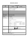
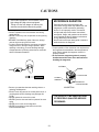
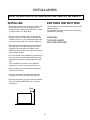
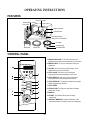
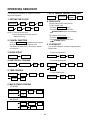
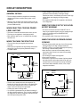
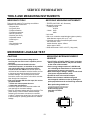
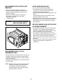
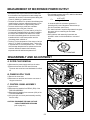
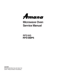
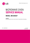
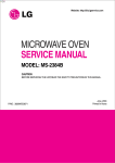
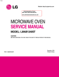
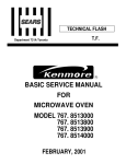
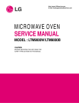
MICROWAVE OVEN
SERVICE MANUAL
MODEL : MB-319ML
MB-319MLA
CAUTION
BEFORE SERVICING THE UNIT, READ THE SAFETY PRECAUTIONS IN THIS MANUAL.
SAFETY PRECAUTIONS
This device is to be serviced only by properly qualified service personnel.
Consult the service manual for proper service procedures to assure continued safety operation and for precautions to be
taken to avoid possible exposure to excessive microwave energy.
PRECAUTIONS TO BE OBSERVED BEFORE AND
DURING SERVICING TO AVOID POSSIBLE
EXPOSURE TO EXCESSIVE MICROWAVE ENERGY
A) Do not operate or allow the oven to be operated with the door open.
B) Make the following safety checks on all ovens to be serviced before activating the magnetron or other
microwave source, and make repairs as necessary; (1) interlock operation, (2) proper door closing, (3)
seal and sealing surfaces (arcing, wear, and other damage), (4) damage to or loosening of hinges and
latches, (5) evidence of dropping or abuse.
C) Before turning on microwave power for any service test or inspection within the microwave generating
compartments, check the magnetron, wave guide or transmission line, and cavity for proper alignment,
integrity, and connections.
D) Any defective or misadjusted components in the interlock, monitor, door seal, and microwave generation
and transmission systems shall be repaired, replaced, or adjusted by procedures described in this manual
before the oven is released to the owner.
CONTENTS
(Page)
SAFETY PRECAUTIONS - - - - - - - - - - - - - - - - - - - - - - - - - - - - - - - - - - - - - - - - - - - - - - - - - - - - - - - - - - - - - - - - - - - - - Inside front cover
SPECIFICATIONS - - - - - - - - - - - - - - - - - - - - - - - - - - - - - - - - - - - - - - - - - - - - - - - - - - - - - - - - - - - - - - - - - - - - - - - - - - - - - - - - - - - - - - - - - - - - - - - - - - - - - 1-1
CAUTIONS - - - - - - - - - - - - - - - - - - - - - - - - - - - - - - - - - - - - - - - - - - - - - - - - - - - - - - - - - - - - - - - - - - - - - - - - - - - - - - - - - - - - - - - - - - - - - - - - - - - - - - - - - - - - - - 2-1
INSTALLATIONS - - - - - - - - - - - - - - - - - - - - - - - - - - - - - - - - - - - - - - - - - - - - - - - - - - - - - - - - - - - - - - - - - - - - - - - - - - - - - - - - - - - - - - - - - - - - - - - - - - - - - - 3-1
OPERATING INSTRUCTIONS - - - - - - - - - - - - - - - - - - - - - - - - - - - - - - - - - - - - - - - - - - - - - - - - - - - - - - - - - - - - - - - - - - - - - - - - - - - - - - - - - - - - 4-1
FEATURES- - - - - - - - - - - - - - - - - - - - - - - - - - - - - - - - - - - - - - - - - - - - - - - - - - - - - - - - - - - - - - - - - - - - - - - - - - - - - - - - - - - - - - - - - - - - - - - - - - - - - - - - - - - - - - - - - - - - - - - - 4-1
CONTROL PANEL - - - - - - - - - - - - - - - - - - - - - - - - - - - - - - - - - - - - - - - - - - - - - - - - - - - - - - - - - - - - - - - - - - - - - - - - - - - - - - - - - - - - - - - - - - - - - - - - - - - - - - - - - - - - - 4-1
OPERATING SEQUENCE- - - - - - - - - - - - - - - - - - - - - - - - - - - - - - - - - - - - - - - - - - - - - - - - - - - - - - - - - - - - - - - - - - - - - - - - - - - - - - - - - - - - - - - - - - - - - - - - - - - - 4-2
SCHEMATIC DIAGRAM - - - - - - - - - - - - - - - - - - - - - - - - - - - - - - - - - - - - - - - - - - - - - - - - - - - - - - - - - - - - - - - - - - - - - - - - - - - - - - - - - - - - - - - - - - - - - - - - - - - - - - 4-3
CIRCUIT DESCRIPTION - - - - - - - - - - - - - - - - - - - - - - - - - - - - - - - - - - - - - - - - - - - - - - - - - - - - - - - - - - - - - - - - - - - - - - - - - - - - - - - - - - - - - - - - - - - - - - - - - - - - - 4-4
SERVICE INFORMATION - - - - - - - - - - - - - - - - - - - - - - - - - - - - - - - - - - - - - - - - - - - - - - - - - - - - - - - - - - - - - - - - - - - - - - - - - - - - - - - - - - - - - - - - - - 5-1
TOOLS AND MEASURING INSTRUMENTS - - - - - - - - - - - - - - - - - - - - - - - - - - - - - - - - - - - - - - - - - - - - - - - - - - - - - - - - - - - - - - - - - - - - - - - - - - - 5-1
MICROWAVE LEAKAGE TEST - - - - - - - - - - - - - - - - - - - - - - - - - - - - - - - - - - - - - - - - - - - - - - - - - - - - - - - - - - - - - - - - - - - - - - - - - - - - - - - - - - - - - - - - - - - - 5-1
MEASUREMENT OF MICROWAVE POWER OUTPUT - - - - - - - - - - - - - - - - - - - - - - - - - - - - - - - - - - - - - - - - - - - - - - - - - - - - - - - - - - - 5-3
DISASSEMBLY AND ADJUSTMENT - - - - - - - - - - - - - - - - - - - - - - - - - - - - - - - - - - - - - - - - - - - - - - - - - - - - - - - - - - - - - - - - - - - - - - - - - - - - - - - - - - - - - 5-3
INTERLOCK CONTINUITY TEST- - - - - - - - - - - - - - - - - - - - - - - - - - - - - - - - - - - - - - - - - - - - - - - - - - - - - - - - - - - - - - - - - - - - - - - - - - - - - - - - - - - - - - - - - - 5-7
COMPONENT TEST PROCEDURE - - - - - - - - - - - - - - - - - - - - - - - - - - - - - - - - - - - - - - - - - - - - - - - - - - - - - - - - - - - - - - - - - - - - - - - - - - - - - - - - - - - - - - 5-8
TROUBLE SHOOTING - - - - - - - - - - - - - - - - - - - - - - - - - - - - - - - - - - - - - - - - - - - - - - - - - - - - - - - - - - - - - - - - - - - - - - - - - - - - - - - - - - - - - - - - - - - - - - - - - - - - - - 5-12
EXPLODED VIEW - - - - - - - - - - - - - - - - - - - - - - - - - - - - - - - - - - - - - - - - - - - - - - - - - - - - - - - - - - - - - - - - - - - - - - - - - - - - - - - - - - - - - - - - - - - - - - - - - - - - - 6-1
REPLACEMENT PARTS LIST - - - - - - - - - - - - - - - - - - - - - - - - - - - - - - - - - - - - - - - - - - - - - - - - - - - - - - - - - - - - - - - - - - - - - - - - - - - - - - - - - - - - 7-1
SCHEMATIC DIAGRAM OF P.C.B. - - - - - - - - - - - - - - - - - - - - - - - - - - - - - - - - - - - - - - - - - - - - - - - - - - - - - - - - - - - - - - - - - - - - - - - - - - - - - - 8-1
PRINTED CIRCUIT BOARD - - - - - - - - - - - - - - - - - - - - - - - - - - - - - - - - - - - - - - - - - - - - - - - - - - - - - - - - - - - - - - - - - - - - - - - - - - - - - - - - - - - - - - - - - - - - - - - - - 8-2
P.C.B. PARTS LIST - - - - - - - - - - - - - - - - - - - - - - - - - - - - - - - - - - - - - - - - - - - - - - - - - - - - - - - - - - - - - - - - - - - - - - - - - - - - - - - - - - - - - - - - - - - - - - - - - - - 9-1
SPECIFICATIONS
DESCRIPTION
ITEM
MB-319ML
MB-319MLA
120 Volts AC 60 Hz
220 Volts AC 60 Hz
MODEL
Power Requirement
MICROWAVE
1,400 Watts (12.0)
GRILL
1,050 Watts
Single phase, 2-wire grounded
Power Output
1,000 Watts full microwave power (IEC60705)
Microwave Frequency
2,450 MHz
Magnetron
2M246
Timer
0 ~ 99 min. 99 sec.
Outside Dimensions
530 (W) x 315 (H) x 394 (D)
Cavity Dimensions
350 (W) x 240 (H) x 365 (D)
Net Weight
16.3 kg (approx.)
Shipping weight
18.7 kg (approx.)
Control Complement
Touch Control System
Clock : 1:00 - 12:59
Microwave Power for Variable Cooking
Power level
HIGH ----------------------------------------Full power throughout the cooking time
9 (Saute) -------------------------approx. 90% of Full power,
8 (Reheat) --------approx. 80%
7 (Med.-High) --------------------approx. 70%,
6 (Medium) --------approx. 60%
5 (Med.-Low) --------------------approx. 50%,
4 (Defrost) ---------approx. 40%
3 (Low) ---------------------------approx. 30%,
2 (Simmer)--------approx. 20%
1 (Warm)--------------------------approx. 10%
Nameplate Location
Back Side
Owner's manual & Cooking guide
Accessories
Glass turntable
Rotating ring
Grill Rack
This microwave oven is designed for household use only.
It is not recommended for commercial purposes.
1-1
CAUTIONS
Unlike other appliances, the microwave oven is
high-voltage and high-current equipment.
Though it is free from danger in ordinary use,
extreme care should be taken during repair.
MICROWAVE RADIATION
Personnel should not be exposed to the
microwave energy which may radiate from the
magnetron or other microwave generating
device if it is improperly used or connection.
All input and output microwave connections,
waveguide, flange, and gasket must be secure
never operate the device without a microwave
energy absorbing load attached.
Never look into an open waveguide or antenna
while the device is energized.
• DO NOT operate on a 2-wire extension cord during
repair and use.
• NEVER TOUCH any oven components or wiring during
operation.
• BEFORE TOUCHING any parts of the oven, always
remove the power plug from the outlet.
• For about 30 seconds after the oven stops, an electric
charge remains in the high voltage capacitor. When
replacing or checking, you must discharge the high
voltage capacitor by shorting across the two terminals
with an insulated screwdriver.
• Proper operation of the microwave oven requires that
the magnetron be assembled to the waveguide and
cavity. Never operate the magnetron unless it is
properly installed.
• Be sure that the magnetron gasket is properly
installed around the dome of the tube whenever
installing the magnetron.
ANTENNA
Gasket
COOLING FIN
FILAMENT
TERMINALS
MAGNETRON
CHASSIS GROUND
MAGNETRON
• Remove your watches whenever working close to or
replacing the Magnetron.
• DO NOT touch any parts of the control panel circuit. A
resulting static electric discharge may damage this
P.C.B.
• NEVER operate the oven with no load.
• NEVER injure the door seal and front plate of the oven
cavity.
• NEVER put iron tools on the magnetron.
• NEVER put anything into the latch hole and the
interlock switches area.
THE OVEN IS TO BE SERVICED ONLY
BY PROPERLY QUALIFIED SERVICE
PERSONNEL.
2-1
INSTALLATIONS
BEFORE YOU BEGIN, READ THE FOLLOWING INSTRUCTIONS COMPLETELY AND CAREFULLY.
INSTALLING
EARTHING INSTRUCTIONS
1. Empty the microwave oven and clean inside it with
a soft, damp cloth. Check for damage such as
misaligned door, damage around the door or dents
inside the cavity or on the exterior.
This microwave oven is designed to be used in a fully
earthed condition.
It is imperative, therefore, to make sure it is properly
earthed before servicing
2. Put the oven on a counter, table, or shelf that is
strong enough to hold the oven and the food and
utensils you put in it. (The control panel side of the
oven is the heavy side. Use care when handling.)
WARNINGTHIS APPLIANCE
MUST BE EARTHED
3. Do not block the vent and the air intake openings.
Blocking vent or air intake openings can cause
damage to the oven and poor cooking results.
Make sure the microwave oven legs are in place to
ensure proper air flow.
4. The oven should not be installed in any area where
heat and steam are generated, because they may
damage the electronic or mechanical parts of the
unit.
Do not install the oven next to a conventional
surface unit or above a conventional wall oven.
5. Use microwave oven in an ambient temperature
less than 104°F(40°C).
6. Place the microwave oven on a sturdy and flat
surface at least 10 cm(4 inches) from the wall.
7. Place the microwave oven as far away as possible
from TV, RADIO, COMPUTER, etc., to prevent
interference.
10cm
3-1
OPERATING INSTRUCTIONS
FEATURES
Oven Front Plate
Window Door Screen
Door Seal
Display Window
Control Panel
Door Open Button
Safety Door Lock System
Turntable
Rotating Ring
Grill Rack
Metal Tray
Turntable Shaft
CONTROL PANEL
1. BRAZILLIAN COOK : This menu has been pre
programmed to cook food automatically by one touch.
2. MENUS LIGHT: To let your microwave cook your
selections.
11
2
3
3. OPTION: You can select on/off of beeper, scroll
speed control and on/off of Demo.
4. AUTO COOK: This oven’s menu has been
preprogrammed to automatically to cook food.
1
5. AUTO REHEAT: This oven’s menu has been to
preprogrammed to automatically reheat food.
4
6. AUTO DEFROST: To select the desired auto weight
defrost programmed with dial.
5
7. AUTO CRISP
6
7
9
8. STOP/CLEAR: To stop oven and clear all entries
except time of day
8
9. MANUAL.
10
10. START: This feature allows oven to begin
functioning.
11. DISPLAY WINDOW: Provides indications of the
functions selected, normally current time displayed.
4-1
OPERATING SEQUENCE
7. AUTO WEIGHT DEFROST COOKING
The following is a description of component functions
during oven operation.
Desliga/Cancela
2X
Auto Descongela
1. SETTING THE CLOCK
Dial
(Number)
Liga
8. CHILD LOCK
Desliga/Cancela
Manual
Liga
Dial
Liga
Dial
This oven has a CHILD LOCK feature
TO SET CHILD LOCK
• Touch the Desliga/Cancela button
• Touch and hold Desliga/Cancela button
DESATIVADO appear on the display.
Liga
Dial
NOTE: 1) This is a 24 hour clock.
2) Clock will operate as long as power is
applied to the oven.
TO CANCEL CHILD LOCK
• Touch the Desliga/Cancela button
• Touch and hold Desliga/Cancela button
ATIVADO appears.
2. CANCEL FUNCTION
Touch the Desliga/Cancela pad whenever you need to
cancel an entry or a function currently in use.
The display will either return to the last item entered
or to the clock.
9. CUSTOM SET
You can select ON/OFF of beeper, language speed,
DEMO mode.
3. QUICK START
• To select sound ON/OFF
Desliga/Cancela
Liga
Desliga/Cancela
4. ONE TOUCH COOKING
Desliga/Cancela
Opções
Liga
• To select language speed.
Pratos Brosileiros
Dial
Desliga/Cancela
Liga
Opções
Liga
Liga
5. TIME COOKING
Desliga/Cancela
Manual
Dial(Power)
• To select DEMO mode.
Liga
Desliga/Cancela
Dial(Time)
Liga
6. MULTI-STAGE COOKING
1ST STAGE
Desliga/Cancela
Dial
Liga
Dial(Time)
Liga
2ND STAGE
Manual
Dial(Time)
Dial(Power)
Liga
Liga
4-2
Opções
Liga
Dial
SCHEMATIC DIAGRAM
4-3
CIRCUIT DESCRIPTION
• A high voltage of approximately 2100 volts AC is
generated in the secondary of the high voltage
transformer which is increased by the action of the high
voltage diode and charging of the high voltage
capacitor.
• The negative 4,000 Volts DC is applied to the filament
of the magnetron.
GENERAL DETAILS
• The low voltage transformer supplies the necessary
voltage to the micom controller when power cord is
plugged in.
• When the door is closed, the primary switch is ON, the
secondary switch is ON, and the monitor switch opens
(contact COM and NO).
WHEN THE OVEN IS SET AT ANY LEVEL
EXCEPT MAXIMUM.
WHEN SELECTING COOKING POWER
LEVEL AND TIME
• The micom controller controls the ON-OFF time of
relay 2 by the applied signal to vary the average output
power of microwave oven as POWER LEVEL.
(refer to page 1-1)
• One complete cycle of the relay 2 is 22 seconds.
• The micom controller memorizes the function you set.
• The time you set appears in the display window.
• Each indicator light turns on to indicate that the stage
has been set.
WHEN THE DOOR IS OPENED DURING
COOKING
WHEN TOUCHING THE START PAD
• The coil of the relay is energized by the micom
controller.
• Power input is supplied to the high voltage transformer
through the fuse to the primary switch and relay 2.
• Turntable rotates.
FUSE
• Both the primary switch and relay 2 cut off the primary
winding voltage of the high voltage transformer.
• ON-OFF of relay 2 is coupled electrically with opening
and closing of the secondary switch.
• When the door is opened, the secondary switch is
opened and when the door is closed, the secondary
switch is closed.
• The cooking time stops counting down.
• Relay stops functioning.
• As the door is opened, if the contact of primary switch
and relay 2 and/or secondary switch fail to open, the
fuse opens due to the large current surge caused by
the monitor switch activation, which, in turn, stops
magnetron oscillation.
PRIMARY
SWITCH
L
MONITOR
SWITCH
N
RELAY 2
H.V.
TRANSFORMER
SECONDARY
SWITCH
FUSE
PRIMARY
SWITCH
L
MICOM CONTROLLER
H.V.
TRANSFORMER
MONITOR
SWITCH
• The fan motor rotates and cools the magnetron by
blowing air (coming from the intake on the base-plate).
• The air is also directed into the oven to exhaust the
vapor in the oven through the upper plate.
• Cooking time starts counting down.
• 3.3 volts AC is generated from the filament winding of
the high voltage transformer. This 3.3 volts is applied to
the magnetron to heat the magnetron filament through
two noise-preventing choke coils.
N
RELAY 2
SECONDARY
SWITCH
MICOM CONTROLLER
4-4
SERVICE INFORMATION
TOOLS AND MEASURING INSTRUMENTS
NECESSARY TOOLS
NECESSARY MEASURING INSTRUMENTS
Tools normally used for TV servicing are sufficient.
Standard tools are listed below.
• Diagonal pliers
• Long nose pliers
• Phillips screwdriver
• Flat blade screwdriver
• Wrench (size 5mm)
• Nutdriver (size 5mm)
• Adjustable wrench
• Soldering iron
• Solder
• Vinyl insulation tape
• Polishing cloth
• TESTER (VOLTS-DC, AC, Ohmmeter)
• Microwave survey meter
- Holaday HI-1500
HI-1501
- Narda 8100
8200
• Inch scale
• 600 cc non conductive material beaker (glass or plastic),
inside diameter: approx. 8.5 cm (31/2 in.)
• Cylindrical and made of borosilicate glass vessel.
max. thickness: 3 mm
outside diameter: approx. 190mm
height: approx. 90mm
• Glass thermometer: 100°C or 212°F (1 deg scale)
MICROWAVE LEAKAGE TEST
CAUTIONS
MEASURING MICROWAVE ENERGY
LEAKAGE
• Be sure to check microwave leakage prior to
servicing the oven if the oven is operative prior to
servicing.
• The service personnel should inform the
manufacture importer, or assembler of any certified
oven unit found to have a microwave emission
level in excess of 5 mW/cm2 and should repair any
unit found to have excessive emission levels at no cost
to the owner and should ascertain the cause of the
excessive leakage. The service personnel should
instruct the owner not to use the unit until the oven has
been brought into compliance.
• If the oven operates with the door open, the service
personnel should:
- Tell the user not to operate the oven.
- Contact the manufacturer.
• The service personnel should check all surface and
vent openings for microwave leakage.
• Check for microwave leakage after every servicing. The
power density of the microwave radiation leakage
emitted by the microwave oven should not exceed
4 mW/cm2. Always start measuring of an unknown field
to assure safety for operating personnel from radiation
leakage.
• Pour 275±15cc of 20±5°C (68±9°F) water in a beaker
which is graduated to 600 cc, and place the beaker
on the center of the turntable.
• Set the energy leakage monitor to 2,450 MHz and
use it following the manufacturer's recommended
test procedure to assure correct result.
• When measuring the leakage, always use the 2-inch
(5cm) spacer supplied with the probe.
• Operate the oven at its maximum output.
• Measure the microwave radiation using and
electromagnetic radiation monitor by holding the
probe perpendicular to the surface being measured
Move probe along shaded area
Probe scanning speed
Less than 2.5 cm/sec
(1 in/sec)
5-1
MEASUREMENT WITH OUTER CASE
REMOVED
NOTES WHEN MEASURING
• Do not exceed meter full scale deflection.
• The test probe must be removed no faster than
1 inch/sec (2.5 cm/sec) along the shaded area,
otherwise a false reading may result.
• The test probe must be held with the grip portion of the
handle.
A false reading may result if the operator's hand is
between the handle and the probe.
• When testing near a corner of the door, keep the probe
perpendicular to the surface making sure the probe
horizontally along the oven surface; this may cause
probe damage.
• When you replace the magnetron, measure for
microwave energy leakage before the outer case is
installed and after all necessary components are
replaced or adjusted.
Special care should be taken in measuring the
following parts. (Circled area of Fig. below)
- Around the magnetron
- The waveguide
WARNING : AVOID CONTACTING ANY
HIGH VOLTAGE PARTS
RECORD KEEPING AND NOTIFICATION
AFTER MEASUREMENT
• After adjustment and repair of any microwave energy
interruption or microwave energy blocking device,
record the measured values for future reference. Also
enter the information on the service invoice.
• The microwave energy leakage should not be more
than 4 mW/cm.sq. after determining that all parts are in
good condition, functioning properly and genuine
replacement parts which are listed in this manual have
been used.
• At least once a year, have the electromagnetic energy
leakage monitor checked for calibration by its
manufacturer.
MEASUREMENT WITH A FULLY
ASSEMBLED OVEN
• After all components, including the outer case, are fully
assembled, measure for microwave energy leakage
around the door viewing window, the exhaust opening,
and air inlet openings.
• Microwave energy leakage must not exceed the values
prescribed below.
NOTE: Leakage with the outer case removed less than
5 mW/cm.sq. Leakage for a fully assembled
oven (Before the latch switch (primary) is
interrupted) with the door in a slightly opened
position-less than 2 mW/cm.sq.
5-2
MEASUREMENT OF MICROWAVE POWER OUTPUT
• Microwave power output measurement is made with
the microwave oven supplied at its rated voltage and
operated at its maximum microwave power setting with
a load of (1000±5) g of potable water.
• The water is contained in a cylindrical borosilicate glass
vessel having a maximum material thickness of 3 mm
and an outside diameter of approximately 190mm.
• The oven and the empty vessel are at ambient
temperature prior to the start of the test.
• The initial temperature (T1) of the water is (10±2)°C It
is measured immediately before the water is added to
the vessel. After addition of the water to the vessel,
the load is immediately placed on the center of the
turntable which is in the lowest position and the
microwave power switched on.
• The time T for the temperature of the water to rise by a
value ∆ T of (10±2)° is measured, where T is the time
in seconds and ∆T is the temperature rise. The initial
and final water temperatures are selected so that the
maximum difference between the final water
temperature and the ambient temperature is 5°.
• The microwave power output P in watts is calculated
from the following formula :
P=
4187 x (∆T)
T
is measured while the microwave generator is
operating at full power. Magnetron filament heat-up
time is not included. (about 3 sec)
• The water is stirred to equalize temperature throughout
the vessel, prior to measuring the final water
temperature.
• Stirring devices and measuring instruments are
selected in order to minimize addition or removal of
heat.
WATER LOAD
TURNTABLE
DISASSEMBLY AND ADJUSTMENT
A. OUTER CASE REMOVAL
Remove the screw
securing
screw
1) Disconnect the power supply cord from the outlet.
2) Remove the screws from the rear of the case.
The outer case must be moved backward to be lifted
off.
B. POWER SUPPLY CORD
1) Remove the outer case.
2) Disconnect two terminals and remove one screw of
the ground terminal.
ground
screw
C. CONTROL PANEL ASSEMBLY
1) Open the door.
2) Disconnect the leadwire from RELAY (RY2) of the
PCB SUB ASSEMBLY.
3) Disconnect the leadwire from connector (CN1) of the
PCB SUB ASSEMBLY.
4) Lift up and pull out control panel assembly carefully
from the cavity.
Lift up and pull out control panel
CAUTION: DISCHARGE THE HIGH VOLTAGE
CAPACITOR BEFORE SERVICING
(refer to page 2-1)
5-3
D. PCB ASSEMBLY REMOVAL
Remove choke cover
1) Remove the control panel assembly from the
cavity. (Refer to control panel assembly removal
on previous page.)
2) Remove screws which hold the PCB SUB
ASSEMBLY to the control panel.
3) Disconnect the flat cable from the PCB SUB
ASSEMBLY and take off the PCB SUB ASSEMBLY.
PCB Sub Asm
Control Panel
Remove door
Door seal plate
E. DOOR MAIN ASSEMBLY REMOVAL
1) Open the door.
2) Remove the choke cover very carefully with a flat-blade
screwdriver.
CAUTION: Be careful not to damage door seal plate
by screwdriver.
3) Lift up and push the door.
NOTE:
1. After replacing the door, be sure to check that the
primary switch, monitor switch, and secondary switch
operate normally.
2. After replacing the door, check for microwave energy
leakage with a survey meter. Microwave energy must
be below the limit of 4 mW/cm. (with a 275 ml water
load)
3. When mounting the door assembly to the oven
assembly, be sure to adjust the door assembly parallel
to the chassis. Also, adjust so the door has no play
between the inner door surface and oven frame
assembly. If the door assembly is not mounted
properly, microwaves may leak from the clearance
between the door and the oven.
Spacer
5-4
F. MAGNETRON REMOVAL
G. REMOVING THE TURNTABLE MOTOR
1) Remove the turntable and rotating ring.
2) Lay the unit down on its back.
3) Remove the turntable motor cover.
The turntable base cover is easily removed by
pinching the eight parts with a wire cutting.
4) Disconnect the leadwire from the turntable motor
terminals.
5) Remove the screw securing the turntable motor to
the oven cavity ASSEMBLY.
6) After repairing the motor, rotate the removed
turntable motor cover.
7) Fit the turntable motor cover’s projecting part to the
base plate slit.
1) Disconnect the leadwire from the magnetron.
2) Carefully remove the mounting screws holding the
magnetron and the waveguide.
3) Remove the magnetron ASSEMBLY until the tube
is clear from the waveguide.
NOTE:
1. When removing the magnetron, make sure its
dome does not hit any adjacent parts, or it may be
damaged.
2. When replacing the magnetron, be sure to install
the magnetron gasket in the correct position and
be sure that the gasket is in good condition.
3. After replacing the magnetron, check for microwave
leakage with a survey meter around the
magnetron. Microwave energy must be below the
limit of 5 mW/cm2. (With a 275 ml. water load).
Make sure that gasket is rigidly attached to the
magnetron. To prevent microwave leakage,
tighten the mounting screws properly, making sure
there is no gap between the waveguide and the
magnetron.
NOTE:
1. Remove the wire lead from the turntable motor
VERY CAREFULLY.
2. Be sure to grasp the connector, not the wires, when
removing.
Air Duct
Magnetron
Waveguide
Dome
Waveguide
Bracket
Magnetron
Gasket
Magnetron
Turntable
Motor
5-5
Wire Leads
H. HIGH VOLTAGE TRANSFORMER
REMOVAL
K. INTERLOCK SYSTEM
1) INTERLOCK MECHANISM
The door lock mechanism is a device which has
been specially designed to eliminate completely
microwave activity when the door is opened during
cooking and thus to prevent the danger resulting
from the microwave leakage.
1) Discharge the high voltage capacitor.
2) Disconnect the leadwire from magnetron, high voltage
transformer, and capacitor.
3) Remove the screw holding the high voltage
transformer to the baseplate.
2) MOUNTING OF THE PRIMARY/MONITOR/
SECONDARY SWITCHES TO THE LATCH
BOARD
3) INSTALLATION AND ADJUSTMENT OF THE
LATCH BOARD TO THE OVEN ASSEMBLY
• Mount the latch board to the oven assembly.
• Adjust the latch board in the arrow direction so that
oven door will not have any play in it when the door
is closed.
• Tighten the mounting screw.
• Check for play in the door by pushing the door
release button. Door movement should be less
than 0.5 mm. (1/64 inch)
Don't push the door release button while making this
adjustment. Make sure that the latch moves
smoothly after adjustment is completed and that the
screws are tight. Make sure the primary, monitor,
and secondary switches operate properly by
following the continuity test procedure.
I. FAN MOTOR ASSEMBLY REMOVAL
1) Discharge the high voltage capacitor.
2) Disconnect the leadwire from fan motor and high
voltage capacitor.
3) Remove the two screws holding the the suction guide
ASSEMBLY to the oven cavity.
4) Remove the two screws holding the fan motor
ASSEMBLY to the suction guide ASSEMBLY.
J. HIGH VOLTAGE CAPACITOR AND
DIODE REMOVAL
1) Discharge the high voltage capacitor.
2) Disconnect the leadwire from fan motor and high
voltage capacitor.
3) Remove the screw holding the suction guide
ASSEMBLY to the oven cavity.
4) Remove the screw holding the high voltage capacitor
bracket and remove the high voltage diode earth
screw.
ADJUSTMENT
DIRECTION
Fan Motor
ASS'Y
SECONDARY
SWITCH
Suction
Guide
H.V.
Capacitor
MONITOR
SWITCH
H.V.
Transformer
H.V.
Diode
PRIMARY
SWITCH
5-6
INTERLOCK CONTINUITY TEST
WARNING : FOR CONTINUED PROTECTION AGAINST EXCESSIVE RADIATION
EMISSION, REPLACE ONLY WITH IDENTICAL REPLACEMENT PARTS.
ALL THESE SWITCHES MUST BE REPLACED AT THE SAME TIME.
TYPE NO. SZM-V 16-FA-63 OR VP-533A-OF FOR PRIMARY SWITCH
TYPE NO. SZM-V 16-FA-62 OR VP-532A-OF FOR MONITOR SWITCH
TYPE NO. SZM-V 16-FA-63 OR VP-533A-OF FOR SECONDARY SWITCH
A. PRIMARY INTERLOCK SWITCH TEST
B. SECONDARY INTERLOCK SWITCH TEST
When the door release button is depressed slowly
with the door closed, an audible click should be
heard at the same time or successively at
intervals. When the button is released slowly, the
latches should activate the switches with an
audible click.
If the latches do not activate the switches when
the door is closed, the switches should be a
adjusted in accordance with the adjustment
procedure. Disconnect the wire lead from the
primary switch. Connect the ohmmeter leads to
the common (COM) and normally open (NO)
terminal of the switch. The meter should indicate
an open circuit in the door open condition.
When the door is closed, the meter should
indicate a closed circuit.
When the primary switch operation is abnormal,
make the necessary adjustment or replace the
switch only with the same type of switch.
COMPONENTS
SWITCHES
(Wire leads removed)
Disconnect the wire lead from the secondary
switch.
Connect the ohmmeter leads to the common
(COM) and normally open (NO) terminals of the
switch. The meter should indicate a open circuit in
the door open condition. When the door is closed,
meter should indicate an closed circuit. When the
secondary switch operation is abnormal, make the
necessary adjustment or replace the switch only
with the same type of switch.
C. MONITOR SWITCH TEST
Disconnect the wire lead from the monitor switch.
Connect the ohmmeter leads to the common
(COM) and normally closed (NC) terminals of the
switch. The meter should indicate closed circuit in
the door open condition. When the door is closed,
meter should indicate an open circuit. When the
monitor switch operation is abnormal, replace with
the same type of switch.
NOTE: After repairing the door or the interlock
system, it is necessary to do this continuity
test before operating the oven.
TEST PROCEDURE
Check for continuity of the
switch with an Ohm-meter
Primary
Switch
Monitor
Switch
Secondary
Switch
RESULTS
Door
open
Door
closed
NO
COM
NC
COM
NO
COM
NOTE : After checking for the continuity of switches, make sure that they are
connected correctly.
5-7
COMPONENT TEST PROCEDURE
CAUTIONS
1. DISCONNECT THE POWER SUPPLY CORD FROM THE OUTLET WHENEVER REMOVING THE
OUTER CASE FROM THE UNIT. PROCEED WITH THE TEST ONLY AFTER DISCHARGING THE HIGH
VOLTAGE CAPACITOR AND REMOVING THE WIRE LEADS FROM THE PRIMARY WINDING OF THE
HIGH VOLTAGE TRANSFORMER. (SEE PAGE 2-1)
2. ALL OPERATIONAL CHECKS WITH MICROWAVE ENERGY MUST BE DONE WITH A LOAD (1 LITER
OF WATER IN CONTAINER) IN THE OVEN.
COMPONENTS
TEST PROCEDURE
RESULTS
HIGH VOLTAGE
TRANSFORMER
(Wire leads removed)
FILAMENT
WINDING
PRIMARY
TERMINAL
1. Measure the resistance.
(Ohm-meter scale: Rx1 and Rx100)
• Primary winding
• Secondary winding
• Filament winding
Approx.: 0.2 ~ 0.4 ohm
Approx.: 60 ~ 90 ohm
Less than: 1 ohm
2. Measure the resistance.
(Ohm-meter scale: Rx1000)
• Primary winding to ground
• Filament winding to ground
Normal: Infinite
Normal: Infinite
MAGNETRON
(Wire leads removed)
1. Measure the resistance.
(Ohm-meter scale: Rx1)
• Filament terminal
Normal: Less than 1 ohm
2. Measure the resistance.
(Ohm-meter scale: Rx1000)
• Filament to chassis
Normal: Infinite
5-8
COMPONENTS
TEST PROCEDURE
RESULTS
Antenna
Gasket
Chassis
Filament
NOTE: When testing the magnetron, be sure to install the magnetron gasket
in the correct position and be sure that the gasket is in good condition.
HIGH VOLTAGE
CAPACITOR
HIGH VOLTAGE
DIODE
NOTE :
Some inexpensive meters
may indicate infinite
resistance in both direction.
Measure the resistance.
(Ohm-meter scale: Rx1000)
• Terminal to terminal.
Normal: Momentarily indicates
several ohms, and
then gradually returns
to infinite.
Measure the resistance.
(Ohm-meter scale: Rx1000)
• Terminal to case.
Normal: Infinite.
Measure the continuity (Forward).
(Ohm-meter scale: Rx10000)
Normal: Continuity.
Abnormal: Infinite.
Measure the continuity (Reverse).
(Ohm-meter scale: Rx10000)
Normal: Infinite.
Abnormal: Continuity.
5-9
COMPONENTS
TEST PROCEDURE
RESULTS
HEATER ELEMENT
Measure the resistance.
Normal:
(Wire leads removed.)
(Multi-meter scale:RX1)
Gill heater
Approx.15 ½
(at 20-30ûC)
Measure the resistance with 500V-100M
Normal:
Ohm insulation resistance meter.
more than 1.0M ½
NOTE: Make sure heater is fully cooled when tested.
MAGNETRON
0ûC~Approx 180ûC
Approx 180ûC
0ûC~Approx 145ûC
Approx 145ûC
THERMOSTAT
OVEN
THERMOSTAT
FUSE
Check the continuity of the switch
(Wire leads removed.)
with an Multi-meter
Normal
Abnormal
NOTE: If the fuse is blown, check primary, the secondary, the monitor
switches, H.V.D and H.V.C before replacing the fuse.
If the fuse is blown by improper switch operation replace the defective
switch and the fuse at the same time.
Replace just the fuse if the switches operate normally.
5-10
COMPONENTS
RELAY 2
TEST PROCEDURE
RESULTS
Check for continuity of relay 2 with an
ohm-meter.
(Remove wire leads from relay 2 and
operate the unit.)
POWER
LEVEL
1
2
3
4
5
6
7
8
9
10
4 sec
6 sec
8 sec
10 sec
12 sec
14 sec
16 sec
18 sec
20 sec
22 sec
18 sec
16 sec
14 sec
12 sec
10 sec
8 sec
6 sec
4 sec
2 sec
0 sec
Relay 2
FAN MOTOR
(Wire leads removed)
Measure the resistance.
(Ohm-meter scale: R x 1)
Normal:
A: Approx. 85 ~ 100 ohm.
B: Approx. 10 ~ 25 ohm.
Abnormal: Infinite or several
ohms.
B
A
TURNTABLE
MOTOR
(Wire leads removed)
Measure the resistance.
(Ohm-meter scale: R x 1 )
Normal: Approx.100~150 ohm
Abnormal: Infinite or several
ohm.
NOTE : • A MICROWAVE LEAKAGE TEST MUST ALWAYS BE PERFORMED WHEN THE UNIT IS
SERVICED FOR ANY REASON.
• MAKE SURE THE WIRE LEADS ARE IN THE CORRECT POSITION.
• WHEN REMOVING THE WIRE LEADS FROM THE PARTS, BE SURE TO GRASP THE
CONNECTOR, NOT THE WIRES.
5-11
TROUBLESHOOTING
WHEN YOU GET A COMPLAINT FROM YOUR CUSTOMER, EVALUATE THE COMPLAINT CAREFULLY. IF
THE FOLLOWING SYMPTOMS APPLY, PLEASE INSTRUCT THE CUSTOMER IN THE PROPER USE OF THE
MICROWAVE OVEN. THIS CAN ELIMINATE AN UNNECESSARY SERVICE CALL.
CAUTIONS
1. Check grounding before checking for trouble.
2. Be careful of the high voltage circuit.
3. Discharge the high voltage capacitor. (See page 2-1)
4. When checking the continuity of the switches or of the high voltage transformer, disconnect one lead wire
from these parts and then check continuity with the AC plug removed. To do otherwise may result in a
false reading or damage to your meter.
5. Do not touch any part of the circuit on the PCB since static electric discharge may damage this control
panel.
Always touch yourself to ground while working on this panel to discharge any static charge built up in your
body. (Micom model only)
CONDITION
CAUSE
REMEDY
Microwave oven
does not work.
Inserting many plugs into one
outlet and using them at the
same time.
(blown fuse or breaker)
Avoid using other electrical
appliances when you use the
microwave oven.
Microwave oven plug is not
inserted tightly.
Insert microwave oven plug
securely.
Low AC input voltage.
Use the microwave oven at
adequate line voltage.
Food temperature is too low.
This may not be a defect.
It is possible that the food
should be cooked for a
longer time period.
Using metallic ware and
allowing it to touch the oven
wall.
Do not use metallic ware for
cooking except that noted in
the cooking guide.
Ceramic ware trimmed in
gold or silver powder is used.
Do not use any type of
cookware with metallic
trimming.
Inconsistent intensity of
microwave by their
characteristics.
1. Use plastic wrap or lid.
2. Stir once or twice while
cooking soup, cocoa or
milk, etc.
Output power is too low.
Sparks occur.
Uneven cooking.
5-12
(TROUBLE 1) The following visual conditions indicate a probable defective control circuit.
1. Incomplete segments.
• Segment missing.
• Partial segment missing.
• Digit flickering (NOTE: Slight flickering is normal.)
2. Colon does not turn on or blink.
3. A distinct change in the brightness of one or more numbers in display.
4. One or more digits in the display are not lighting.
5. Display indicates a number different from one touched, for example, key in 5 and 3 appears in the display.
6. Specific numbers (for example 7 or 9) will not display when key pad is touched.
7. Display does not count down with time blinking or up with clock operation.
8. Display obviously jumps in time while counting down.
9. Display counts down too fast while cooking.
10. Each indicator light does not turn on after setting cooking cycle.
11. Display time of day does not reappear when cooking is finished.
CONDITION
CHECK
1. No input can be
programmed.
Check the connection between
membrane key
assembly and
PCB assembly.
Continuity
Defective PCB
assembly.
Replace PCB
assembly.
No continuity
Loose
connection.
Connect them
tightly.
Replace key
membrane
assembly and
check operation.
Everything works
as specified.
Defective key
membrane
assembly.
Replace key
membrane
assembly.
Defective PCB
assembly.
Replace PCB
assembly.
2. Some inputs
cannot be
programmed.
3. Display shows a
number or figure
different from one
touched.
RESULT
Still have trouble.
4. Random
programming
when touching
other pads.
5. Display is fixed
at some figure
and can not
accept any
input.
5-13
CAUSE
REMEDY
(TROUBLE 2) Oven does not operate at all, display window does not display any figures,
and no input is accepted.
CONDITION
1. Fuse blows.
CHECK
Check continuity
of monitor
switch (with
door closed).
RESULT
Continuity.
CAUSE
REMEDY
Malfunction of the
monitor switch.
Replace fuse,
primary, monitor,
secondary
switches, and
RELAY(RY2) of
P.C.B Assembly.
Shorted contact at
the primary switch.
Replace fuse,
primary, monitor,
secondary
switches, and
RELAY(RY2) of
P.C.B Assembly.
No continuity.
Replace fuse
Check continuity
of primary
switch (with
door opened).
Continuity.
Check continuity
of secondary
switch (with
door opened).
Continuity.
Disconnect one
side of the wire
lead connected
from transformer
to the high
voltage
capacitor and
operate the unit.
No continuity.
Malfunction of
secondary switch.
No continuity.
Replace fuse,
primary, monitor,
secondary
switches, and
RELAY(RY2) of
P.C.B Assembly.
Normal.
Defective high
voltage capacitor.
Replace high
voltage capacitor.
Fuse blows again
Defective high voltage transformer.
Replace high voltage transformer.
NOTE : All these switches must be replaced at the same time. Refer to page 5-7, 5-8
2. Fuse does not
blow.
Check continuity
of thermostat.
No continuity.
Defective
thermostat.
Replace
thermostat.
Defective power
supply cord.
Replace power
supply cord.
Continuity.
Check continuity
of power supply
cord.
No continuity.
5-14
(TROUBLE 3) Display shows all figures set, but oven does not start cooking while desired
program times are set and START pad is touched.
CONDITION
CHECK
1. Setting time
does not count
down when
touching START
pad.
Check continuity
of secondary
switch (with
door closed).
2. Fan motor or
oven lamp do
not turn on.
RESULT
No continuity.
CAUSE
REMEDY
Defective
secondary switch.
Replace
secondary switch.
Continuity.
Check the connection between
CN1 connector
and PCB
assembly.
Continuity
Defective PCB
assembly.
Replace PCB
assembly.
No continuity
Loose connection.
Connect them
tightly.
Check fan motor.
Abnormal
Defective fan motor.
Replace fan motor.
Check oven lamp.
Abnormal
Defective oven lamp.
Replace oven lamp.
Normal
(TROUBLE 4) Oven seems to be operating but little heat is produced in oven load.
CONDITION
Output is low
CHECK
Check the
power source
voltage.
RESULT
CAUSE
REMEDY
Lower than 90% of
rating voltage.
Decrease in power
source voltage
with load.
Suggest customer
contact local
electric power
utility company
or qualified
electrician.
Defective PCB
assembly.
Replace PCB
assembly.
Defective
magnetron.
Replace
magnetron.
Normal
Disconnect the
wire leads from
relay 2 and
check on and off
time with
multitester.
Measure the
output power.
Abnormal
Normal
Abnormal
NOTE : Simple test of power output-conducted by heating one liter water for one min. if available.
Minimum 8.5°C temperature rise is normal condition.
5-15
(TROUBLE 5) No microwave oscillation even though oven lamp and fan motor run.
(Display operates properly)
CONDITION
No microwave
oscillation.
CHECK
Disconnect the
wire leads from
relay 2 and
check continuity
of relay 2.
(Operate the unit)
Check high voltage transformer
RESULT
No continuity.
CAUSE
REMEDY
Defective PCB
assembly.
Replace PCB
assembly.
Defective high
voltage
transformer.
Replace high
voltage
transformer.
Defective high
voltage capacitor.
Replace high
voltage capacitor.
Defective high
voltage diode.
Replace high
voltage diode.
Defective
magnetron.
Replace
magnetron.
Continuity.
Abnormal
Normal
Check high voltage capacitor.
Abnormal
Normal
Check high voltage diode.
Abnormal
Normal
Check
magnetron.
Abnormal
NOTE : • Make sure the wire leads are in the correct position.
• When removing the wire leads from the parts, be sure to grasp the connector, not the wires.
• When removing the magnetron, be sure to install the magnetron gasket in the correct position
and in good condition.
Output is full power
when you set lower
power level.
Disconnect the
wire leads from
relay 2 and check
continuity relay 2.
(Operate the unit)
Abnormal.
5-16
Defective PCB
assembly.
Replace PCB
assembly.
EXPLODED VIEW
INTRODUCTION
OVEN CAVITY PARTS
INTERIOR PARTS
BASE PLATE PARTS
DOOR PARTS
LATCH BOARD PARTS
CONTROL PANEL PARTS
6-1
DOOR PARTS
13581A
15006A
13552A
13536A
13213A
14890A
13720D
14026A
14970A
6-2
CONTROLLER PARTS
268711
24781S
268712
WTT028
250205
23572A
250202
WTP004
23790D
250203
249401
250204
24510L
243501
24970A
250201
6-3
OVEN CAVITY PARTS
33112U
WTT021
948504
33550H
33052M
WNZ015
340511
WTT010
35300S
35026G
33390G
WSZ184
34036W
34370T
35889A
36549S
948501
33390M
WTP013
6-4
LATCH BOARD PARTS
43501A
WSZ085
466001
43500A
466003
466001
6-5
INTERIOR PARTS
568771
56411A
56930V
50FZZA
56930V
54826A
55006F
WTT028
WSZ002
56549F
54974S
WSZ002
55900A
WTT037
34930W
35012A
WSZ002
948502
56324A
50CZZH
56912B
WSZ002
56851D
55262A
54810C
WTT028
6-6
WSZ002
BASE PLATE PARTS
63303L
56170D
63302L
948503
647781
WTT028
63302R
WSZ002
368771
63303R
WTT021
6-7
REPLACEMENT PARTS LIST
LOC.
NO.
*01
*02
*05
13213A
13536A
13552A
13581A
13720D
14026A
14890A
14970A
15006A
23572A
23790D
243501
24510L
24781S
249401
24970A
250201
250202
250203
250204
250205
268711
268712
33052M
33112U
33390G
33390M
33550H
34036W
340511
34370T
34930W
35012A
35026G
35300S
35889A
36549S
368771
43500A
43501A
466001
466001
PART NO.
3828W5A1811
3828W5S1726
3850W3D065A
3213W1A028B
3536WRA001L
3552W1A037A
3581W1A250B
3720W0D180C
4026W2A012A
4890W1D039W
4970WRA001C
5006W3A017A
3572W0A221C
3790W2A001B
4350W3A022A
4510W3L004A
4781W1S086H
4940W3A020A
4B72023A
5020W2A159A
5020W2A158A
5020W3A141A
5020W2A084A
5020W3A140A
6871W2S234B
6871W2S233A
3052W3M011C
3112W1U015S
3390W1G010A
3390W1A011A
3550W1A084B
4036W3W001A
4051W3A001A
4370W3A003A
4B72510F
5012W3A020A
5026W1A037E
5300W1S002C
5889W2A005J
6549W1S002A
4B75297B
3500W1A004A
3501W1A003H
3B73362F
3B73362F
DESCRIPTION
MANUAL,OWNERS
MANUAL,SERVICE
LABEL,COOKING GUIDE
DOOR FRAME ASSEMBLY
SEAL TAPE
CHOKE COVER
DOOR ASSEMBLY
PANEL,DOOR
LATCH
GLASS
SPRING
CAP,CHOKE COVER
PANEL,CONTROL
WINDOW,DIGITRON
RING
LEVER
CONTROLLER ASSEMBLY,SEMI MICOM
KNOB
SPRING
BUTTON
BUTTON
BUTTON
BUTTON
BUTTON
PWB(PCB) ASSEMBLY,SUB
PWB(PCB) ASSEMBLY,SUB
CANOPY,MICA
OUT CASE,U-BENDING
TRAY,GLASS
TRAY,METAL
COVER,HEATER
SEAL
RIVET ASSEMBLY
SHAFT,TURN TABLE
HOLDER,WIRE
INSULATOR
SHELF
HEATER,SHEATH
ROTATING RING ASSEMBLY
MOTOR(CIRC),SYNCHRONOUS
HARNESS
BOARD,LATCH
BOARD ASSEMBLY,LATCH
SWITCH,MICRO
SWITCH,MICRO
SVC
R
R
R
R
R
R
R
R
R
R
R
R
R
R
R
R
R
R
R
B
R
B
R
B
R
R
R
R
R
R
R
R
R
R
R
R
R
R
R
R
R
R
R
R
R
ALTER
8ABS0160958
6549W1S016A
6600W1K004C
3B73362E
R: SERVICE PARTS
7-1
LOC.
NO.
466003
466003
50CZZH
50FZZA
54810C
54826A
54974S
55006F
55262A
55900A
56170D
56170D
56324A
56411A
56549F
56851D
568771
56912B
56930V
63302L
63302R
63303L
63303R
647781
948501
948502
948503
948504
WNZ015
WSZ002
WSZ085
WSZ184
WTP004
WTP013
WTT010
WTT021
WTT028
WTT037
PART NO.
3B73361E
3B73361E
6120W3H003F
3B74133K
4810W4C003C
4B70774A
4974W1S010A
5006WRA002A
5262W2A041A
2B72125B
6170W1D061A
6170W1D061A
6324W1A001B
6411W1A022B
6549W1F005B
6021W3B001M
6877W1A283B
6912W3B002G
6930WRT001B
3302W1A036G
3302W1A035G
3303W1A028M
3303W2A004K
4B73900A
4850W4C001D
4850W4C001J
3B72244G
3B72244C
4B71028B
1SBF0402418
4B70188C
1SZZW2Z001E
1TPL0302418
1TPL0402418
1TTG0402422
1TTL0402418
1TTL0402818
1TTL0403818
DESCRIPTION
SWITCH,MICRO
SWITCH,MICRO
CAPACITOR,DRAWING[HIGH VOLTAGE]
FUSE,DRAWING
BRACKET,CAPACITOR
SPACER
GUIDE,SUCTION
CAP,FUSE
DUCT
FAN
TRANSFORMER,HIGH VOLTAGE
TRANSFORMER,HIGH VOLTAGE
MAGNETRON
POWER CORD ASSEMBLY
MOTOR(CIRC),FAN
CABLE ASSEMBLY
HARNESS
LAMP,DRAWING
THERMOSTAT
BASE PLATE
BASE PLATE
BASE PLATE ASSEMBLY
BASE PLATE ASSEMBLY
LEG
CUSHION
CUSHION
CUSHION
CUSHION
NUT,DRAWING
SCREW TAP TITE(S),BINDING HEAD
SCREW,DRAWING
SCREW,DRAWING
SCREW TAPPING,PAN HEAD
SCREW TAPPING,PAN HEAD
SCREW TAPPING,TRUSS HEAD
SCREW TAPPING,TRUSS HEAD
SCREW TAPPING,TRUSS HEAD
SCREW TAPPING,TRUSS HEAD
SVC
R
R
R
R
R
R
R
R
R
R
R
R
R
R
R
R
R
R
R
R
R
R
R
R
R
R
R
R
R
R
R
R
R
R
R
R
R
R
ALTER
6600W1K004B
3B73361D
0CZZW1H002F
6170W1D023B
6170W1D050A
6549W1F007B
6021W3B001K
R: SERVICE PARTS
7-2
SCHEMATIC DIAGRAM OF P.C.B.
8-1
PRINTED CIRCUIT BOARD
8-2
P.C.B PARTS LIST
LOC.
NO.
AR3
C01
C02
C03
C03
C04
C05
C06
C10
C11
C20
C21
C25
C80
C81
C82
C84
CU4
D01
D02
D03
D10
D20
D30
D31
D32
D33
DP1
EN01
LED1
Q01
Q02
Q20
Q30
Q31
Q33
Q50
Q80
R01
R01
R02
R02
R03
R04
R10
R11
R12
R13
R20
R21
R22
R25
PART NO.
0RZ4702G610
0CK1040K949
0CE2276H638
0CE2276H638
0CE2276H638
0CE4756K638
0CK2230K949
0CK1040K949
0CK2230K949
0CE4766K638
0CK2230K949
0CK2230K949
0CK2230K949
0CK2210K519
0CK2210K519
0CK2210K519
0CK2210K519
4850W4C001D
0DD400209AD
0DD400209AD
0DD400209AD
0DD400209AD
0DD414809AD
0DD414809AD
0DD414809AD
0DD414809AD
0DD414809AD
6302W5A015A
6024WRYA06B
0DLZW5A003A
0TR126609AA
0TR126609AA
0TR107009AD
0TR105009AB
0TR105009AB
0TR105009AB
0TR107009AD
0TR107009AD
0RD1501G609
0RD1501F609
0RD1501G609
0RD4701F609
0RD1001F609
0RD1001F609
0RD0202F609
0RD0102F609
0RD0102F609
0RD1003F609
0RD1001F609
0RD2202F609
0RD1001F609
0RD3901F609
DESCRIPTION
RESISTOR,DRAWING
CAPACITOR,FIXED CERAMIC
CAPACITOR,FIXED ELECTROLYTIC
CAPACITOR,FIXED ELECTROLYTIC
CAPACITOR,FIXED ELECTROLYTIC
CAPACITOR,FIXED ELECTROLYTIC
CAPACITOR,FIXED CERAMIC
CAPACITOR,FIXED CERAMIC
CAPACITOR,FIXED CERAMIC
CAPACITOR,FIXED ELECTROLYTIC
CAPACITOR,FIXED CERAMIC
CAPACITOR,FIXED CERAMIC
CAPACITOR,FIXED CERAMIC
CAPACITOR,FIXED CERAMIC
CAPACITOR,FIXED CERAMIC
CAPACITOR,FIXED CERAMIC
CAPACITOR,FIXED CERAMIC
CUSHION
DIODE,SWITCHING
DIODE,SWITCHING
DIODE,SWITCHING
DIODE,SWITCHING
DIODE,SWITCHING
DIODE,SWITCHING
DIODE,SWITCHING
DIODE,SWITCHING
DIODE,SWITCHING
DIGITRON
VOLUME,ROTARY
LED
TRANSISTOR,BIPOLARS
TRANSISTOR,BIPOLARS
TRANSISTOR,BIPOLARS
TRANSISTOR,BIPOLARS
TRANSISTOR,BIPOLARS
TRANSISTOR,BIPOLARS
TRANSISTOR,BIPOLARS
TRANSISTOR,BIPOLARS
RESISTOR,FIXED CARBON FILM
RESISTOR,FIXED CARBON FILM
RESISTOR,FIXED CARBON FILM
RESISTOR,FIXED CARBON FILM
RESISTOR,FIXED CARBON FILM
RESISTOR,FIXED CARBON FILM
RESISTOR,FIXED CARBON FILM
RESISTOR,FIXED CARBON FILM
RESISTOR,FIXED CARBON FILM
RESISTOR,FIXED CARBON FILM
RESISTOR,FIXED CARBON FILM
RESISTOR,FIXED CARBON FILM
RESISTOR,FIXED CARBON FILM
RESISTOR,FIXED CARBON FILM
SPECIFICATION
SVC
47KOHM 1/4W 5% 3216 BULK 8 PIN
0.1UF D 50V 80%,-20% F(Y5V) TA52
220UF SMS,SG 25V 20% FM5 TP 5
220UF SMS,SG 25V 20% FM5 TP 5
220UF SMS,SG 25V 20% FM5 TP 5
4.7UF SMS,SG(HR) 50V 20% FM5 TP 5
22NF D 50V 80%,-20% F(Y5V) TA52
0.1UF D 50V 80%,-20% F(Y5V) TA52
22NF D 50V 80%,-20% F(Y5V) TA52
47UF SMS,SG 50V 20% FM5 TP 5
22NF D 50V 80%,-20% F(Y5V) TA52
22NF D 50V 80%,-20% F(Y5V) TA52
22NF D 50V 80%,-20% F(Y5V) TA52
220PF D 50V 10% B(Y5P) TA52
220PF D 50V 10% B(Y5P) TA52
220PF D 50V 10% B(Y5P) TA52
220PF D 50V 10% B(Y5P) TA52
9T 15W 40L RUBBER
1N4002 PYUNG CHANG TP52 DO41
1N4002 PYUNG CHANG TP52 DO41
1N4002 PYUNG CHANG TP52 DO41
1N4002 PYUNG CHANG TP52 DO41
1N4148 PYUNG CHANG TP52 DO35
1N4148 PYUNG CHANG TP52 DO35
1N4148 PYUNG CHANG TP52 DO35
1N4148 PYUNG CHANG TP52 DO35
1N4148 PYUNG CHANG TP52 DO35
HNM-07SS30 7 AMB-314XF W/POOL
ES1005A SEIL 24CLICK LGEAZ
LITEON LTL-12BGE-1 BK GREEN NA
KEC KTA1266-Y(KTA1015) TP TO92
KEC KTA1266-Y(KTA1015) TP TO92
KEC KRC 107M TP TO92M 50V 100MA
KEC KRC105M(KRC1205) TP TO92
KEC KRC105M(KRC1205) TP TO92
KEC KRC105M(KRC1205) TP TO92
KEC KRC 107M TP TO92M 50V 100MA
KEC KRC 107M TP TO92M 50V 100MA
1.5K OHM 1/4 W 5% TA52
1.5K OHM 1/6 W 5% TA52
1.5K OHM 1/4 W 5% TA52
4.7K OHM 1/6 W 5% TA52
1K OHM 1/6 W 5% TA52
1K OHM 1/6 W 5% TA52
20 OHM 1/6 W 5% TA52
10 OHM 1/6 W 5% TA52
10 OHM 1/6 W 5% TA52
100K OHM 1/6 W 5% TA52
1K OHM 1/6 W 5% TA52
22K OHM 1/6 W 5% TA52
1K OHM 1/6 W 5% TA52
3.9K OHM 1/6 W 5% TA52
R
R
R
R
R
R
R
R
R
R
R
R
R
R
R
R
R
R
R
R
R
R
R
R
R
R
R
R
R
R
R
R
R
R
R
R
R
R
R
R
R
R
R
R
R
R
R
R
R
R
R
R
R: SERVICE PARTS
9-1
ALTER
LOC.
NO.
R26
R50
R51
R55
R70
R71
R73
R75
R80
R81
R82
R83
R84
R90
R91
R92
R93
R94
R95
R96
RY1
RY1
RY1
RY3
SW01
SW02
SW03
SW04
SW05
SW06
SW07
SW08
SW09
SW10
U01
ZD1
ZD2
PART NO.
0RD1001F609
0RD1001F609
0RD2700F609
0RD1004F609
0RD2202F609
0RD1202F609
0RD4702F609
0RD4702F609
0RD5601F609
0RD5601F609
0RD1001F609
0RD4701F609
0RD1001F609
0RD5601F609
0RD5601F609
0RD5601F609
0RD5601F609
0RD5601F609
0RD5601F609
0RD5601F609
6920W5A008A
6920W5A008A
6920W5A008A
6920W2YD04A
6600W5R004A
6600W5R004A
6600W5R004A
6600W5R004A
6600W5R004A
6600W5R004A
6600W5R004A
6600W5R004A
6600W5R004A
6600W5R004A
0IZZW5A106A
0DZ510009AF
0DZ750009BB
DESCRIPTION
SPECIFICATION
RESISTOR,FIXED CARBON FILM
RESISTOR,FIXED CARBON FILM
RESISTOR,FIXED CARBON FILM
RESISTOR,FIXED CARBON FILM
RESISTOR,FIXED CARBON FILM
RESISTOR,FIXED CARBON FILM
RESISTOR,FIXED CARBON FILM
RESISTOR,FIXED CARBON FILM
RESISTOR,FIXED CARBON FILM
RESISTOR,FIXED CARBON FILM
RESISTOR,FIXED CARBON FILM
RESISTOR,FIXED CARBON FILM
RESISTOR,FIXED CARBON FILM
RESISTOR,FIXED CARBON FILM
RESISTOR,FIXED CARBON FILM
RESISTOR,FIXED CARBON FILM
RESISTOR,FIXED CARBON FILM
RESISTOR,FIXED CARBON FILM
RESISTOR,FIXED CARBON FILM
RESISTOR,FIXED CARBON FILM
RELAY
RELAY
RELAY
RELAY
SWITCH,TACT
SWITCH,TACT
SWITCH,TACT
SWITCH,TACT
SWITCH,TACT
SWITCH,TACT
SWITCH,TACT
SWITCH,TACT
SWITCH,TACT
SWITCH,TACT
IC,DRAWING
DIODE,ZENERS
DIODE,ZENERS
1K OHM 1/6 W 5% TA52
1K OHM 1/6 W 5% TA52
270 OHM 1/6 W 5% TA52
1M OHM 1/6 W 5% TA52
22K OHM 1/6 W 5% TA52
12K OHM 1/6 W 5% TA52
47K OHM 1/6 W 5% TA52
47K OHM 1/6 W 5% TA52
5.6K OHM 1/6 W 5% TA52
5.6K OHM 1/6 W 5% TA52
1K OHM 1/6 W 5% TA52
4.7K OHM 1/6 W 5% TA52
1K OHM 1/6 W 5% TA52
5.6K OHM 1/6 W 5% TA52
5.6K OHM 1/6 W 5% TA52
5.6K OHM 1/6 W 5% TA52
5.6K OHM 1/6 W 5% TA52
5.6K OHM 1/6 W 5% TA52
5.6K OHM 1/6 W 5% TA52
5.6K OHM 1/6 W 5% TA52
DQ1U DAIICHI 250VAC 3A 12VDC
DQ1U DAIICHI 250VAC 3A 12VDC
DQ1U DAIICHI 250VAC 3A 12VDC
OZF-S-112LM1P OEG 240VAC 16A
IT-1102AH-T 200 IN SUNG 15V 20MA
IT-1102AH-T 200 IN SUNG 15V 20MA
IT-1102AH-T 200 IN SUNG 15V 20MA
IT-1102AH-T 200 IN SUNG 15V 20MA
IT-1102AH-T 200 IN SUNG 15V 20MA
IT-1102AH-T 200 IN SUNG 15V 20MA
IT-1102AH-T 200 IN SUNG 15V 20MA
IT-1102AH-T 200 IN SUNG 15V 20MA
IT-1102AH-T 200 IN SUNG 15V 20MA
IT-1102AH-T 200 IN SUNG 15V 20MA
HITACHI 64 DIP BK BRAZIL
UZ-5.1BS PYUNG CHANG TP52 DO34
UZ-7.5BS PYUNG CHANG TP52 DO34
SVC
R
R
R
R
R
R
R
R
R
R
R
R
R
R
R
R
R
R
R
R
R
R
R
R
R
R
R
R
R
R
R
R
R
R
R
R
R
ALTER
6920W5A007A
6920W2D010B
6920W2D010A
6920W5A012A
R: SERVICE PARTS
9-2
P/NO : 3828W5S1726
Aug., 2002
Printed in Korea