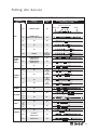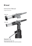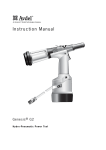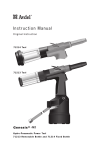
1
Manual de Instruções
07
53
7
Tr a d u ç âo d a s i n s t r u ç õ e s o r i g i n a i s
0753
Genesis® 7537
F e r r a m e n t a H i d ro - P n e u m á t i c a
7
Índice
Regras de Segurança
4
Especificações
Especificações para a Ferramenta 07537
Dimensões da Ferramenta
5
5
Finalidade de Utilização
6
Colocação ao Serviço
Abastecimento de Ar
Cursor Mecânico
Cursor
Para Carregar e Recarregar a Ferramenta
Para Carregar a Ferramenta
Para Recarregar a Ferramenta
Procedimento de Operação
Identificação e Orientação das Molas
Seguidoras de Mandril
Conjuntos de Ponta
Garras de Ponta
Selecção de uma Garra de Ponta
Selecção de Garra de Ponta - Medidas Inglesas
Selecção de Garra de Ponta - Sistema Metrico
Mandris e Molas Seguidoras de Mandril
Chobert® e Grovit® - Medidas Inglesas
Chobert® e Grovit® - Sistema Metrico
Briv® - Medidas Inglesas
Tipos de Cabeças de Mandril e Comprimento ‘P’
Briv® - Sistema Metrico
Avlug®, Avsert®, Avtronic® e Rivscrew® Medidas Inglesas
Manutenção da ferramenta
Diariamente
Semanalmente
Dados de segurança da massa Moly-Lithium EP 3735
Dados de segurança para
Dados de Segurança para a massa Lubrificante
MolyKote® 55m
Dados de Segurança para a massa Lubrificante
MolyKote® 111
Kit de Manutenção
7
8
9
910
10
10
10
Manutenção
Desmontagem da 07537-00200
Conjunto Geral e Lista de Peças da 07537-00200
Preparação
Detalhes do Óleo
Dados de Segurança Óleo
Hyspin® VG 32 e AWS
Bomba de Preparação
Procedimento de Preparação
Resolução de Problemas
Sintoma, Possível Causa e Solução
24-25
26-27
28
28
28
29
30
11
12
13
14
15
16
16
16
18
19
19
20
21
21
21
22
22
22
23
GARANTIA LIMITADA
A Avdel oferece a garantia limitada de que os seus produtos estarão isentos de defeitos de fabrico e materiais
que ocorram em condições de operação normal. Esta Garantia Limitada irá depender: (1) do produto ser
instalado, mantido e utilizado de acordo com as instruções e a documentação sobre o produto e (2) da
confirmação, por parte da Avdel, desse defeito, após inspecção e teste. A Avdel oferece a mencionada garantia
limitada por um período de doze (12) meses, a partir da entrega do produto da Avdel ao comprador directo da
Avdel. Em caso de qualquer incumprimento da mencionada garantia, a única solução será a devolução dos Bens
defeituosos para a sua substituição ou reembolso do preço da compra, ao critério da Avdel. A GARANTIA
LIMITADA EXPRESSA E SOLUÇÃO ANTERIORMENTE MENCIONADAS SÃO EXCLUSIVAS E SUBSTITUEM TODAS AS
OUTRAS GARANTIAS E SOLUÇÕES. A AVDEL EXONERA-SE E EXCLUI ESPECIFICAMENTE QUALQUER GARANTIA
IMPLÍCITA DE QUALIDADE, ADEQUAÇÃO A UM FIM OU COMERCIALIZAÇÃO DO PRODUTO.
A política da Avdel UK Limited é de desenvolvimento e melhoramento contínuos de produto e reservámos o direito de alterar as especificações de qualquer produto sem aviso prévio.
3
Regras de Segurança
Este manual de instruções tem de ser lido pela pessoa que irá instalar, operar ou fazer a manutenção
desta ferramenta prestando atenção especial às seguintes regras de segurança.
1
Utilize apenas para a finalidade para que foi concebida.
2
Não utilize equipamento com esta ferramenta/máquina que não seja o recomendado e fornecido pela Avdel UK Limited.
3
Qualquer modificação efectuada pelo cliente à ferramenta/máquina, conjuntos de ponta, acessórios ou qualquer equipamento
fornecido por Avdel UK Limited ou seus representantes, será da inteira responsabilidade do cliente. A Avdel UK Limited terá todo o
prazer em aconselhar sobre qualquer modificação proposta.
4
A ferramenta/máquina terá de ser mantida sempre em condição de segurança e inspeccionada a intervalos regulares quanto a
danos e operada por pessoal competente e treinado. Qualquer procedimento de desmontagem será realizado apenas por pessoal
formado em procedimentos Avdel UK Limited. Não desmonte a ferramenta/máquina sem primeiro consultar as instruções de
manutenção. Contacte a Avdel UK Limited com os seus requisitos de formação.
5
A ferramenta/máquina deverá ser sempre operada de acordo com a legislação de Saúde e Segurança pertinente. No R.U. aplicase a norma de 1974 “Saúde e Segurança no Trabalho etc.”. Quaisquer perguntas que digam respeito à operação correcta da
ferramenta/máquina e segurança do operador deverão ser feitas directamente à Avdel UK Limited.
6
As precauções a ter em conta ao utilizar esta ferramenta/máquina terão de ser explicadas pelo cliente a todos os operadores.
7
Desligue sempre a linha de ar da entrada da ferramenta/máquina antes de tentar ajustar, montar ou remover o conjunto de ponta.
8
Não opere uma ferramenta/máquina que esteja apontada na direcção de pessoas.
9
Adopte sempre uma posição equilibrada e firme antes de operar a ferramenta/máquina.
10 Assegure-se de que os orifícios de respiro não ficam bloqueados ou cobertos e de que os tubos estão sempre em boa condição.
11 A pressão de funcionamento não deverá exceder as 7 bar – 100 lbf/pol. ao quadrado.
12 A combinação de elemento de fixação, mandril, tamanho de furo e espessura de chapa deverá estar de acordo com as
especificações da Avdel UK Limited.
13 Não opere a ferramenta se esta não estiver equipada com um conjunto de ponta completo, excepto se especificado em contrário.
14 Ao utilizar a ferramenta, é necessário o uso de óculos de protecção, tanto pelo operador como pelas pessoas que se encontram
na proximidade para proteger contra projecção de elementos de fixação, no caso de um elemento de fixação ser colocado "no ar".
Recomendamos a utilização de luvas se existirem arestas ou cantos vivos na aplicação.
15 Tenha cuidado para evitar que roupas soltas, gravatas, cabelo comprido, trapos de limpeza etc. sejam apanhados pelas partes
móveis da ferramenta, esta deverá ser mantida limpa e seca para a melhor agarração possível.
16 Ao transportar a ferramenta de lugar para lugar mantenha as mãos afastadas do gatilho/alavanca para evitar o arranque
inadvertido.
17 Contacto excessivo com o óleo hidráulico deverá ser evitado. Para minimizar a possibilidade de irritações da pele, deverá ter
cuidado para lavar muito bem.
I M P O R TA N T E
Embora um pouco de desgaste e marcação ocorra naturalmente através da utilização normal e correcta de
mandris, estes devem ser examinados regularmente quanto a desgaste e marcações excessivas, com atenção
especial ao diâmetro da cabeça, à área de agarração das garras posteriores do encabadouro ou este estar muito
picado e quaisquer distorções de mandril. Os mandris que falham durante a utilização poderão sair forçadamente
da ferramenta. É da responsabilidade do cliente assegurar-se de que os mandris são substituídos antes de
apresentarem quaisquer níveis excessivos de desgaste e sempre antes do número máximo recomendado de
colocações. Contacte o seu representante da Avdel UK Limited que lhe dirá qual é esse número medindo a carga
de escareação da sua aplicação com uma ferramenta de teste calibrada. Estas ferramentas também podem ser
compradas sob a referência 07900-09080 e são fornecidas com toda a informação necessária para testar
neste manual.
4
Especificaçoes
Especificações para a Ferramenta 07537
Pressão de ar
5 - 7 bars (70 - 100 lbf/pol.2)
Mínimo - Máximo
2
Volume de ar livre necessário
@ 5,1 bar / 75 lbf/pol.
2,6 litros (,09 pés3)
Curso
Mínimo
28 mm (1,10 pol)
2
Força de tracção
@ 5,5 bar / 80 lbf/pol.
3,89 kN (875 lbf)
Tempo de ciclo
Aproximadamente
1 segundo
Nível de ruído
Inferior a
70 dB(A)
Peso
Ferramenta
2,3 kg (5,06 lb)
Vibração
Inferior a
2,5 m/s2 (8 pés/s2)
Medidas da ferramenta
REFERÊNCIA 07537-00200
60
2.36
475
18.70
53
07
50
1.96
7
338
13.30
163 140
6.41 5.51
98
3.85
121
51
2
075
37
120
150
110
5
Finalidade de Utilização
A ferramenta pneumática 07537 leve e portátil foi concebida para colocar elementos Avdel® a alta velocidade (excepto Avlug® 1/16")
tornando-a ideal para montagem por lotes ou em fluxo numa grande variedade de aplicações em todos os tipos de indústrias.
As referências indicadas são para a encomenda de uma ferramenta completa sem o equipamento de ponta.
A referência da ferramenta para o modelo 07537 é 07537-00200. Consulte os conjuntos gerais nas páginas 86 e 87.
A ferramenta coloca a maior parte dos elementos de fixação de repetição, conforme apresentado na tabela abaixo.
A ferramenta deve-se utilizar com equipamento de ponta específico. Deverá consultar a secção Equipamento de Ponta do manual ao
seleccionar componentes compatíveis quanto ao tipo e tamanho do elemento de fixação utilizado na sua aplicação (vejas as páginas 72-80).
As dimensões das garras de ponta estão indicadas nas páginas 73.
2,4 mm
CHOBERT®
●
GROVIT®
●
AVLUG®
●
●
BRIV®
●
●
3,2 mm
4,0 mm
4,8 mm
6,4 mm
●
●
●
●
●
●
●
●
●
2,5 mm
2,8 mm
3 mm
3,5 mm
4 mm
●
●
6 mm
M2.5
4-40
UNC
M3
6-32
UNC
●
RIVSCREW®
●
AVTRONIC®
●
AVSERT®
6
TAMANHO DO ELEMENTO DE FIXAÇÃO
NOME DO ELEMENTO
DE FIXAÇÃO
●
●
●
Colocação ao Serviço
Abastecimento de ar
Todas as ferramentas são operadas com ar comprimido a uma pressão óptima de 5,5 bars. Recomendamos a utilização de
reguladores de pressão e sistemas automáticos de lubrificação/filtração no abastecimento de ar principal. Estes devem ser instalados
a uma distância da ferramenta inferior a 3 metros (veja diagrama abaixo) para assegurar vida máxima e manutenção mínima da
ferramenta.
Os tubos de abastecimento de ar deverão ter um valor de pressão mínimo eficaz de trabalho de 150% da pressão máxima produzida
no sistema ou 10 bars, aquele que for maior. Os tubos de ar deverão ser resistentes a óleo, ter um exterior resistente ao desgaste e
deverão ser protegidos onde as condições de operação possam causar danos aos mesmos. Todos os tubos de ar TÊM de ter um
diâmetro interno mínimo de 6,4 mm (1/4 polegada).
Leia os detalhes da manutenção diária na página 81.
07
53
7
TORNEIRA DE FECHAMENTO
(UTILIZADA DURANTE A MANUTENÇÃO DO
FILTRO/REGULADOR OU UNIDADES DE LUBRIFICAÇÃO)
PONTO DE DESPRENDIMENTO
DO ABASTECIMENTO
PRINCIPAL
MÁXIMO DE 3 METROS
0 2 4
1416
12
6 8 10
PONTO DE DRENAGEM
DO ABASTECIMENTO PRINCIPAL
07 53 7
REGULADOR DE PRESSÃO E FILTRO
(DRENAR DIARIAMENTE)
7
Colocação ao serviço
07
53
7
Cursor Mecânico
0753
7
Para referência existem três tipos diferentes de cursores mecânicos:
•
•
•
07271-01100
07279-05843
07279-05845
Utilizado para mandris padrão e mandris descartáveis de 5/32".
Utilizado para mandris descartáveis de 1/8".
Utilizado para mandris descartáveis de 3/8".
A diferença entre os conjuntos acima reside no diâmetro interno do bujão extremo.
BUJÃO EXTREMO
Estes estão codificados por cores, veja abaixo:
OURO
PRATA
8
Colocação ao Serviço
Cursor
IMPORTANTE
Se montado incorrectamente, o cursor não permite a alimentação dos elementos de fixação.
Embora o cursor esteja montado na posição correcta quando a ferramenta é fornecida, recomendamos que verifique a sua orientação
antes de montar o equipamento de ponta. A extremidade do cursor ligeiramente côncava carregada por mola deverá apontar para a
parte da frente da ferramenta como se mostra na ilustração abaixo.
Quando montado na posição correcta, o cursor deslizará facilmente para fora do cano quando um mandril é empurrado para o seu
centro e depois puxado para trás.
Para inverter a orientação do cursor, siga estes passos:
Os números dos itens em negrito referem-se ao conjunto geral e à
lista de peças para o tipo 07530-00200 nas páginas 86-87.
CURSOR
EXTREMIDADE CARREGADA
POR MOLA
•
Remova a pinça 48 e deslize a tampa da extremidade 50.
•
Utilizando uma chave tipo Allen, remova um parafuso de cabeça
oca 5 certificando-se de que expele todo o ar aprisionado.
Remova o segundo parafuso de cabeça oca 5.
•
Puxe para fora o bujão traseiro 47.
•
Puxe para fora o conjunto do pistão das garras posteriores 51
juntamente com as garras 34.
•
Eleve e tire a mola 35 e o alojamento das garras 41.
•
Insira um mandril no furo na extremidade traseira do cano 44 até ficar saliente através da frente do cano, depois, puxe para
fora o mandril e o cursor juntos através da frente.
•
Faça a montagem pela ordem inversa da desmontagem.
•
Insira o Conjunto do Cursor Mecânico 36 na frente do cano, com a orientação correcta.
CANO DA
FERRAMENTA
GARRAS
DE PONTA
Para Caregar a Ferramenta
IMPORTANTE
O procedimento para carregar a ferramenta e para montar o equipamento de ponta na ferramenta é integral.
Ao encomendar uma ferramenta completa ou sistema este, normalmente, ser-lhe-á fornecido com todo o equipamento de ponta necessário
para o elemento de fixação a ser colocado. Para identificar os componentes do equipamento de ponta ou para seleccionar os elementos
correctos, leia a secção do equipamento de ponta, nas páginas 72-80.
Se tiverem sido fornecidos uma garra de ponta, mandris e molas seguidoras de mandril continue com o carregamento da ferramenta e a
montagem do equipamento de ponta conforme se apresenta na página seguinte.
Os números dos itens em negrito referem-se ao conjunto geral e à lista de peças para o tipo 07530-00200 nas páginas 86-87.
9
Colocação ao Serviço
Para Carregar a Ferramenta
•
Ligue o abastecimento de ar à ferramenta.
•
Abra as garras posteriores 34 que agarram o mandril, desligando o comutador das garras posteriores (itens 22 e 23).
•
Aparafuse as garras de ponta seleccionadas no cano 44 da ferramenta.
•* Insira um mandril na extremidade posterior dos elementos de fixação através do saco de papel.
•
Deslize a mola seguidora de mandril no mandril certificando-se de que a orientação é correcta, conforme se apresenta na tabela
na página 88.
•
Agarrando a extremidade posterior do mandril, rasgue o saco de papel em volta dos elementos de fixação.
•
Abra as garras de ponta rodando o anel exterior nas garras operadas por Came ou empurrando para fora nas extremidades das
garras, como se mostra na ilustração da esquerda abaixo.
•
Insira o mandril montado previamente, a mola seguidora de mandril e os elementos de fixação na garra de ponta até que o
primeiro elemento de fixação a ser colocado fique saliente nas garras de ponta.
•
Feche as garras de ponta e ajuste de maneira que o primeiro elemento de fixação fique saliente de 1,5 mm a 3 mm (1/16" a
1/8"), como se mostra na ilustração da direita abaixo.
•
Feche as garras posteriores para garantir que o mandril está agarrado, ligando o interruptor da garra posterior (itens 22 e 23).
1.5mm - 3mm
(1/16" - 1/8")
Para Recarregar a Ferramenta
•
Abra as garras posteriores 34 da ferramenta.
•
Abra as garras de ponta e puxe o mandril vazio e a mola seguidora de mandril para fora da ferramenta.
•
Volte a carregar a ferramenta seguindo as instruções acima, começando na fase •*.
Procedimento de Operação
IMPORTANTE
Deve verificar que a orientação do cursor e o equipamento de ponta estão correctos antes de tentar operar
a ferramenta.
•
Empurre o elemento de fixação, até ficar saliente das garras de ponta, completamente nos furos da aplicação assegurando-se
que a ferramenta é mantida firme e correctamente.
•
Opere o gatilho sem soltar - a cabeça de mandril é puxada através do elemento de fixação, formando o elemento de fixação na
aplicação.
•
Remova a ferramenta.
•
Solte o gatilho. O elemento de fixação seguinte estará automaticamente presente através das garras de ponta, pronto para ser
colocado.
Os números dos itens em negrito referem-se ao conjunto geral e à lista de peças para o tipo 07530-00200 nas páginas 86-87.
10
Colocação ao Serviço
IDENTIFICAÇÃO E ORIENTAÇÃO DAS MOLAS SEGUIDORAS DE MANDRIL
ELEMENTO DE FIXAÇÃO
NOME
TAMANHO
GARRAS DE PONTA
(VEJA A SECÇÃO EQUIPAMENTO DE PONTA)
TAMANHO DE
MANDRIL
MANDRIL/MOLA SEGUIDORA DE MANDRIL E
CONJUNTO DE ELEMENTO DE FIXAÇÃO
MOLA SEGUIDORA DE MANDRIL
BRIV ®
CÓNICA PADRÃO
3/32"
ACESSO LIMITADO E ACESSO
LIMITADO OPERADO POR CAMES
TODOS
1/8"
TODAS
TODOS
5/32"
TODAS
TODOS
3/16"
TODAS
TODOS
6 mm
PADRÃO
TODOS EXCEPTO
a
3 MEDIDA
SUPERIOR
3/32"
TODAS EXCEPTO
CÓNICA PADRÃO,
ACESSO LIMITADO
TODOS
3/32"
CÓNICA PADRÃO,
ACESSO LIMITADO
TODOS
1/8"
TODAS
TODOS
5/32"
TODAS
TODOS EXCEPTO
a
3 MEDIDA
SUPERIOR
5/32"
TODAS
3 MEDIDA
SUPERIOR
3/16"
TODAS
TODOS EXCEPTO
a
2 MEDIDA
SUPERIOR
3/16"
TODAS
2 MEDIDA
SUPERIOR
1/4"
TODAS
TODOS
TODAS
TODOS
TODAS
TODOS
TODAS
TODOS
6 x 32
UNC
TODAS
TODOS
2.5 mm
TODAS
TODOS
2.8 mm
TODAS EXCEPTO
ACESSO LIMITADO
TODOS
2.8 mm
ACESSO LIMITADO
TODOS
CHOBERT ®
AVLUG ®
GROVIT ®
CABEÇA DE MANDRIL
3/32"
CHOBERT ®
GROVIT ®
CHOBERT ®
TODOS
VIROLA
MANDRIL
MOLA
a
a
2.8 mm
RIVSCREW ®
3 mm
3.5 mm
4 mm
2.5 mm
AVSERT ®
4 x 40
UNC
3 mm
AVTRONIC ®
11
Conjuntos de Ponta
Nas ferramentas de rebitagem rápida tais como o tipo 0753 Mk II, o equipamento de ponta é sempre constituído por três elementos;
uma garra de ponta, um mandril e uma mola seguidora. Os três itens são específicos ao elemento de fixação a ser colocado e ao
tamanho do furo na aplicação.
I M P O R TA N T E
Para evitar a desmontagem completa da ferramenta é essencial verificar a orientação do cursor antes de
montar o equipamento de ponta à ferramenta. Veja a secção "CURSOR" na página 69.
É essencial que o equipamento de ponta correcto seja montado na ferramenta para assegurar
colocação efectiva do elemento de fixação e operação SEGURA da ferramenta. LEIA AS INSTRUÇÕES
DE SEGURANÇA com cuidado na página 64.
Para identificar a combinação correcta do equipamento de ponta para montar na sua ferramenta, seleccione uma garra de ponta
lendo a secção abaixo, depois leia a secção de mandril para seleccionar as referências para o mandril e para a mola seguidora de
mandril. Mandris e molas seguidoras de mandril estão ilustrados na página 71.
Para montar o equipamento de ponta, siga o procedimento de "Para Carregar a Ferramenta" na página 70.
Garras de Ponta
I M P O R TA N T E
Uma garra de ponta incorrecta poderá resultar num elemento de fixação incorrectamente colocado
ou um aperto incorrecto.
As garras de ponta podem ser classificadas em 7 tipos básicos diferentes como desenhado ao lado, embora as dimensões internas
variem de acordo com o elemento de fixação para as quais se destinam. As dimensões exactas que se referem às letras nas
ilustrações ao lado são indicadas nas 'Tabelas de selecção de garra de ponta' nas páginas 74-75.
Para uma forma especial, poderão existir várias opções de formas de extremidade dando benefícios de acesso ou melhoramentos de
colocação de elementos de fixação.
Plana
•
•
Forma de extremidade normal de todas as garras de ponta.
Adequada para todas as aplicações sem restrições de acesso.
Universal
•
•
Concebida para utilização com elementos de fixação Chobert® de cabeça universal.
Também pode ser utilizado com os elementos de fixação Briv® para obter o maior aperto possível. Nota: isto reduz a gama de
aperto máximo do elemento de fixação Briv® de aproximadamente 0,4 mm (0,015").
Recuada
•
•
APENAS para utilização com os elementos de fixação Briv®.
Dá um aperto maior do que uma forma de extremidade plana mas menor do que uma forma de extremidade universal, sem
redução da gama de agarração do elemento de fixação.
Cónica
•
•
Disponível como se mostra nas "Tabelas de selecção de garra de ponta".
Permite maior acessibilidade que uma forma de extremidade plana e coloca a mesma gama.
Formação de cabeça
•
•
12
APENAS para utilização com os elementos de fixação Rivscrew®.
Deforma as cabeças dos elementos de fixação para atingir um bom aperto.
Conjuntos de Ponta
Selecção de uma Garra de Ponta
•
Faça a lista do nome, tamanho e material do elemento de fixação a ser colocado.
•
Procure este elemento de fixação na primeira coluna das tabelas de selecção de
garra de ponta na página 74 se utilizar medidas inglesas e na página 75 se utilizar
unidades métricas.
•
Procurando através da tabela, anote quais as garras de ponta disponíveis. APENAS
as que se mostram estão disponíveis.
•
Seleccione aquela que é mais adequada para a sua aplicação consultando o
respectivo desenho das garras de ponta. Se a sua aplicação não tiver restrições de
acesso, deverá seleccionar a forma padrão com uma forma de extremidade plana
com ou sem came.
PADRÄO
'B'
28.6
1.125
'E'
33.5
1.32
'D'
PLANA UNIVERSAL RECUADA CÓNICA
Disponível para colocar a maioria dos elementos de
fixação. Permite uma maior penetração em
aplicações sem outras restrições de acesso.
LONGA
LONGA
LONGA
LONGA CURVA
CURVA
ACESSO LIMITADO
LIMITADO
ACESSO
'B'
'B'
28,6
28,6
1,125
1,125
'B'
'B'
'B'
'B'
'F'
'F'
33,5
33,5
1,32
1,32
'D'
'D'
'E'
'E'
28,6
28,6
1,125
1,125
REBITE
REBITE
Ø
Ø
11/8
/8
55/32
/32
33/16
/16
PLANA
PLANA
33,5
33,5
1,32
1,32
'D'
'D'
'E'
'E'
'E
'E''
41,4
41,4
1,63
1,63
'D'
'D'
'F'
'F'
mm
mm pol.
pol.
,620
,620 15,7
15,7
,690
17,5
,690 17,5
,720
,720 18,3
18,3
PLANA
PLANA
RECUADA
RECUADA
UNIVERSAL
UNIVERSAL
20,5
20,5
0,81
0,81
RECUADA
RECUADA
PLANA
PLANA
Disponível para colocar a maioria dos
elementos de fixação. Permite uma maior
penetração em aplicações sem outras
restrições de acesso.
Disponível como se mostra na TABELA DE
SELECÇÃO DE GARRA DE PONTA. Permite mais
penetração em aplicações com acesso restrito.
Os mandris devem ser curvados à mão para
seguir a forma da garra.
Disponível como se mostra na TABELA DE
SELECÇÃO DE GARRA DE PONTA.
Permite o acesso em aplicações muito
restritivas.
ACESSO
LIMITADO
OPERADA
A CAMES
PADRÃO
OPERADA
A CAMES
LONGA OPERADA A CAMES
ACESSO ACESSO
LIMITADOLIMITADO
OPERADA A CAMES
'B''B'
'B'
'B'
'B''B'
28.6
28,6
1.25
1,25
28,6
20,5
1,25
0,81
'E''E'
34
37,1
1.34
1,46
'D'
'D'
'E''E'
34
34
1,34
1,34
'D'
'D'
'E'
'E'
28,6
28,6
1,25
1,25
PLANA
PLANA
FORMAÇÃO
DE CABEÇA (FC)
PLANA
PLANA
37,1
41,4
1,46
1,63
'D''D'
PLANA
PLANA
Disponível como se mostra na TABELA DE SELECÇÃO DE GARRA DE PONTA no verso. Funções equivalentes à Padrão e Acesso Limitado acima com a adição de
uma came para facilitar e tornar mais rápida a abertura das garras de ponta e por conseguinte mais rápido o procedimento de recarregamento de saco.
As dimensões que se mostram em negrito são em milímetros. As outras dimensões são em polegadas.
13
Conjuntos de Ponta
Selecção - Medidas Inglesas
A coluna de Nº REF. faz referência cruzada com as colunas de Nº Ref. na secção de mandril. Identifica tanto o mandril como a mola
seguidora de mandril necessária para uma garra de ponta especial com elemento de fixação específico.
Nº
REF.
ELEMENTO
DE FIXAÇÃO
3/32" CHOBERT®
& GROVIT
1/8" CHOBERT®
& GROVIT
5/32" CHOBERT®
& GROVIT
3/16" CHOBERT®
& GROVIT
1/4" CHOBERT®
3/32" BRIV®
Apenas latão
GARRAS DE PONTA
DIMENSÕES
'B'
'D'
'E'
TIPO E FORMA
DA EXTREMIDADE
REF.
1
PADRÃO - PLANA
07150-03003
,36
1,30
,16
1
PADRÃO OPERADO A CAMES - PLANA
07170-04500
,36
1,30
,16
2
PADRÃO - CÓNICA
07170-03103
,36
1,30
4
LONGA - PLANA
07150-04003
,41
5
PADRÃO - PLANA
07150-03004
5
PADRÃO - CÓNICA
6
Nº
REF.
GARRAS DE PONTA
DIMENSÕES
'B'
'D'
'E'
TIPO E FORMA
DA EXTREMIDADE
REF.
1
# PADRÃO - UNIVERSAL
07150-03203
,36
1,33
,24
1
ACESSO LIMITADO OPERADO A CAMES
07177-03003
,20
1,18
,16
,16
3
ACESSO LIMITADO
07274-01000
,22
1,07
,16
2,30
,16
4
LONGA CURVA - PLANA
07150-05003
,41
2,28
,16
,41
1,18
,20
5
# PADRÃO - UNIVERSAL
07150-03204
,41
1,22
,32
07170-03104
,41
1,19
,20
5
PADRÃO OPERADO A CAMES - PLANA
07170-04600
,41
1,18
,20
LONGA - PLANA
07150-04004
,41
2,18
,20
6
# LONGA - UNIVERSAL
07150-04204
,41
2,22
,30
6
LONGA CURVA - PLANA
07150-05004
,41
2,12
,20
6
LONGA OPERADO A CAMES - PLANA
07170-05000
,41
2,18
,20
7
PADRÃO - PLANA
07150-03005
,48
1,30
,24
7
# PADRÃO - UNIVERSAL
07150-03205
,48
1,35
,41
7
PADRÃO - CÓNICA
07150-03105
,44
1,30
,24
7
PADRÃO OPERADO A CAMES - PLANA
07170-04700
,48
1,30
,24
8
LONGA - PLANA
07150-04005
,48
2,30
,24
8
# LONGA - UNIVERSAL
07150-04205
,48
2,35
,42
8
LONGA CURVA - PLANA
07150-05005
,48
2,23
,24
8
LONGA OPERADO A CAMES - PLANA
07170-05100
,48
2,30
,24
9
PADRÃO - PLANA
07150-03006
,56
1,18
,33
9
# PADRÃO - UNIVERSAL
07150-03206
,56
1,24
,47
9
PADRÃO - CÓNICA
07150-03106
,56
1,18
,33
9
PADRÃO OPERADO A CAMES - PLANA
07170-04800
,56
1,18
,33
10
LONGA - PLANA
07150-04006
,56
2,30
,33
10
# LONGA - UNIVERSAL
07150-04206
,56
2,39
,48
10
LONGA CURVA - PLANA
07150-05006
,56
2,21
,33
10
LONGA OPERADO A CAMES - PLANA
07170-05200
,56
2,30
,33
11
PADRÃO - CÓNICA
07150-03008
,64
1,18
,39
11
PADRÃO OPERADO A CAMES - PLANA
07170-04900
,64
1,18
,39
12
LONGA - PLANA
07150-04008
,64
2,18
,39
12
LONGA OPERADO A CAMES - PLANA
07170-05300
,64
2,18
,39
13
PADRÃO - CÓNICA
07170-03103
,36
1,30
,15
14
ACESSO LIMITADO OPERADO A CAMES
07177-03003
,20
1,18
,16
14
ACESSO LIMITADO
07274-01000
,22
1,07
,16
-
-
-
-
-
-
15
PADRÃO - PLANA
07150-03004
,41
1,18
,20
15
PADRÃO - RECUADA
07170-03004
,41
1,20
,30
1/8" BRIV®
15
PADRÃO - CÓNICA
07170-03104
,41
1,19
,20
16
LONGA - PLANA
07150-04004
,41
2,18
,20
Liga Al.,
Latão, Aço
16
LONGA - RECUADA
07170-03204
,41
2,18
,30
16
LONGA CURVA - PLANA
07150-05004
,41
2,12
,20
16
LONGA CURVA - RECUADA
07170-03304
,41
2,12
,30
-
-
-
-
-
-
5/32" BRIV®
17
PADRÃO - PLANA
07150-03005
,48
1,30
,24
17
PADRÃO - RECUADA
07170-03005
,48
1,32
,41
Liga Al.,
Latão, Aço
18
LONGA - PLANA
07150-04005
,48
2,30
,24
18
LONGA - RECUADA
07170-03205
,48
2,30
,41
18
LONGA CURVA - PLANA
07150-05005
,48
2,23
,24
18
LONGA CURVA - RECUADA
07170-03305
,48
2,23
,41
19
PADRÃO - PLANA
07150-03005
,48
1,30
,24
19
PADRÃO - RECUADA
07170-03005
,48
1,32
,41
20
LONGA - PLANA
07150-04005
,48
2,30
,24
20
LONGA - RECUADA
07170-03205
,48
2,30
,41
20
LONGA CURVA - PLANA
07150-05005
,48
2,23
,24
20
LONGA CURVA - RECUADA
07170-03305
,48
2,23
,41
3/16" BRIV®
21
PADRÃO - PLANA
07150-03006
,56
1,18
,33
21
PADRÃO - RECUADA
07170-03006
,56
1,20
,47
Liga Al.,
Latão, Aço
22
LONGA - PLANA
07150-04006
,56
2,30
,33
22
LONGA - RECUADA
07170-03206
,56
2,30
,47
22
LONGA CURVA - PLANA
07150-05006
,56
2,21
,33
22
LONGA CURVA - RECUADA
07170-03306
,56
2,21
,47
23
PADRÃO - PLANA
07150-03006
,56
1,18
,33
23
PADRÃO - RECUADA
07170-03006
,56
1,20
,47
24
LONGA - PLANA
07150-04006
,56
2,30
,33
24
LONGA - RECUADA
07170-03206
,56
2,30
,47
24
LONGA CURVA - PLANA
07150-05006
,56
2,21
,33
24
LONGA CURVA - RECUADA
07170-03306
,56
2,21
,47
25
PADRÃO OPERADO A CAMES
07170-05600
,64
1,21
,52
25
PADRÃO - PLANA
07170-05800
,64
1,21
,52
26
LONGA OPERADO A CAMES
07170-05700
,64
2,19
,52
26
LONGA - PLANA
07170-05900
,64
2,19
,52
27
PADRÃO - PLANA
07150-03003
,36
1,30
,16
27
PADRÃO - CÓNICA
07150-03103
,36
1,30
,16
27
PADRÃO OPERADO A CAMES - PLANA
07170-04500
,36
1,30
,16
28
LONGA - PLANA
07150-04003
,41
2,30
,16
28
LONGA CURVA - PLANA
07150-05003
,41
2,28
,16
-
-
-
-
-
29
PADRÃO - PLANA
07150-03004
,41
1,18
,20
29
PADRÃO - CÓNICA
07170-03104
,41
1,19
,20
29
PADRÃO OPERADO A CAMES - PLANA
07170-04600
,41
1,18
,20
30
LONGA - PLANA
07150-04004
,41
2,18
,20
30
LONGA CURVA - PLANA
07150-05004
,41
2,12
,20
30
LONGA OPERADO A CAMES - PLANA
07170-05000
,41
2,18
,20
31
PADRÃO - PLANA
07150-03003
,36
1,30
,16
-
-
-
-
-
-
32
PADRÃO - PLANA
07150-03004
,41
1,18
,20
32
PADRÃO OPERADO A CAMES - PLANA
07170-04600
,41
1,18
,20
33
PADRÃO - PLANA
07150-03003
,36
1,30
,16
33
ACESSO LIMITADO OPERADO A CAMES
07271-08000
,41
1,18
,16
34
LONGA - PLANA
07150-04003
,41
2,30
,16
-
-
-
-
-
-
35
PADRÃO - PLANA
07271-05600
,36
1,30
,16
36
ACESSO LIMITADO OPERADO A CAMES
07271-08100
,40
1,18
,16
5/32" BRIV®
Apenas Aço Inox.
3/16" BRIV®
Apenas Aço Inox.
6mm BRIV®
Liga Al.,
Latão, Aço
3/32" AVLUG®
1/8" AVLUG®
2,5 mm, 4-40 UNC
AVSERT®
3,0 mm, 6-32 UNC
AVSERT®
2,5 mm AVTRONIC®
®
2,8 mm AVTRONIC
37
LONGA - PLANA
07271-05900
,41
2,30
,16
-
-
-
-
-
-
2,8 mm RIVSCREW®
38
PADRÃO OPERADO A CAMES - FC
07271-03000
,41
1,18
,24
-
-
-
-
-
-
3,0 mm RIVSCREW®
39
PADRÃO OPERADO A CAMES - FC
07271-03000
,41
1,18
,24
-
-
-
-
-
-
3,5 mm RIVSCREW®
40
PADRÃO OPERADO A CAMES - FC
07271-03500
,41
1,18
,24
-
-
-
-
-
-
4,0 mm RIVSCREW®
41
PADRÃO OPERADO A CAMES - FC
07271-04000
,41
1,18
,25
-
-
-
-
-
-
# Estas garras de ponta são adequadas para colocar rebites Chobert® com uma Forma de Cabeça Universal. Quando utilizadas no tamanho
equivalente de Briv®, é atingido o aperto maior possível. Note que ao utilizar elementos de fixação Briv®, a agarração máxima é reduzida de
aproximadamente 0,4 mm (0,015").
14
Conjuntos de Ponta
Selecção de Garra de Ponta - Sistema Métrico
ELEMENTO
DE FIXAÇÃO
3/32" CHOBERT®
& GROVIT
1/8" CHOBERT®
& GROVIT
5/32" CHOBERT®
& GROVIT
3/16" CHOBERT®
& GROVIT
1/4" CHOBERT®
3/32" BRIV®
Apenas latão
Nº
REF.
GARRAS DE PONTA
TIPO E FORMA
DA EXTREMIDADE
REF.
DIMENSÕES
'B'
'D'
'E'
Nº
REF.
GARRAS DE PONTA
TIPO E FORMA
DA EXTREMIDADE
REF.
'B'
DIMENSÕES
'D'
'E'
1
PADRÃO - PLANA
07150-03003
9,14 33,02 4,06
1
# PADRÃO - UNIVERSAL
07150-03203
9,14 33,78 6,10
1
PADRÃO OPERADO A CAMES - PLANA
07170-04500
9,14 33,02 4,06
1
ACESSO LIMITADO OPERADO A CAMES
07177-03003
5,08 29,97 4,06
2
PADRÃO - CÓNICA
07170-03103
9,14 33,02 4,06
3
ACESSO LIMITADO
07274-01000
5,59 27,18 4,06
4
LONGA - PLANA
07150-04003
10,41 58,42 4,06
4
LONGA CURVA - PLANA
07150-05003 10,41 57,91 4,06
5
PADRÃO - PLANA
07150-03004
10,41 29,97 5,08
5
# PADRÃO - UNIVERSAL
07150-03204 10,41 30,99 8,13
5
PADRÃO - CÓNICA
07170-03104
10,41 30,23 5,08
5
PADRÃO OPERADO A CAMES - PLANA
07170-04600 10,41 29,97 5,08
6
LONGA - PLANA
07150-04004
10,41 55,37 5,08
6
# LONGA - UNIVERSAL
07150-04204 10,41 56,39 7,62
6
LONGA CURVA - PLANA
07150-05004
10,41 53,85 5,08
6
LONGA OPERADO A CAMES - PLANA
07170-05000 10,41 55,37 5,08
7
PADRÃO - PLANA
07150-03005
12,19 33,02 6,10
7
# PADRÃO - UNIVERSAL
07150-03205 12,19 34,29 10,41
7
PADRÃO - CÓNICA
07150-03105
11,18 33,02 6,10
7
PADRÃO OPERADO A CAMES - PLANA
07170-04700 12,19 33,02 6,10
8
LONGA - PLANA
07150-04005
12,19 58,42 6,10
8
# LONGA - UNIVERSAL
07150-04205 12,19 59,69 10,67
8
LONGA CURVA - PLANA
07150-05005
12,19 56,64 6,10
8
LONGA OPERADO A CAMES - PLANA
07170-05100 12,19 58,42 6,10
9
PADRÃO - PLANA
07150-03006
14,22 29,97 8,38
9
# PADRÃO - UNIVERSAL
07150-03206 14,22 31,50 11,94
9
PADRÃO - CÓNICA
07150-03106
14,22 29,97 8,38
9
PADRÃO OPERADO A CAMES - PLANA
07170-04800 14,22 29,97 8,38
10
LONGA - PLANA
07150-04006
14,22 58,42 8,38
10
# LONGA - UNIVERSAL
07150-04206 14,22 60,71 12,19
10
LONGA CURVA - PLANA
07150-05006
14,22 56,13 8,38
10
LONGA OPERADO A CAMES - PLANA
07170-05200 14,22 58,42 8,38
11
PADRÃO - PLANA
07150-03008
16,26 29,97 9,91
11
PADRÃO OPERADO A CAMES - PLANA
07170-04900 16,26 29,97 9,91
12
LONGA - PLANA
07150-04008
16,26 55,37 9,91
12
LONGA OPERADO A CAMES - PLANA
07170-05300 16,26 55,37 9,91
13
PADRÃO - CÓNICA
07170-03103
9,14 33,02 3,81
14
ACESSO LIMITADO OPERADO A CAMES
07177-03003
14
ACESSO LIMITADO
07274-01000
5,59 27,18 4,06
-
-
-
15
PADRÃO - PLANA
07150-03004
10,41 29,97 5,08
15
PADRÃO - RECUADA
07170-03004 10,41 30,48 7,62
5,08 29,97 4,06
-
-
-
1/8" BRIV®
15
PADRÃO - CÓNICA
07170-03104
10,41 30,23 5,08
16
LONGA - PLANA
07150-04004 10,41 55,37 5,08
Liga Al.,
Latão, Aço
16
LONGA - RECUADA
07170-03204
10,41 55,37 7,62
16
LONGA CURVA - PLANA
07150-05004 10,41 53,85 5,08
16
LONGA CURVA - RECUADA
07170-03304
10,41 53,85 7,62
-
-
5/32" BRIV®
17
PADRÃO - PLANA
07150-03005
12,19 33,02 6,10
17
PADRÃO - RECUADA
07170-03005 12,19 33,53 10,41
Liga Al.,
Latão, Aço
18
LONGA - PLANA
07150-04005
12,19 58,42 6,10
18
LONGA - RECUADA
07170-03205 12,19 58,42 10,41
18
LONGA CURVA - PLANA
07150-05005
12,19 56,64 6,10
18
LONGA CURVA - RECUADA
07170-03305 12,19 56,64 10,41
19
PADRÃO - PLANA
07150-03005
12,19 33,02 6,10
19
PADRÃO - RECUADA
07170-03005 12,19 33,53 10,41
20
LONGA - PLANA
07150-04005
12,19 58,42 6,10
20
LONGA - RECUADA
07170-03205 12,19 58,42 10,41
5/32" BRIV®
Apenas Aço Inox.
-
-
-
-
20
LONGA CURVA - PLANA
07150-05005
12,19 56,64 6,10
20
LONGA CURVA - RECUADA
07170-03305 12,19 56,64 10,41
3/16" BRIV®
21
PADRÃO - PLANA
07150-03006
14,22 29,97 8,38
21
PADRÃO - RECUADA
07170-03006 14,22 30,48 11,94
Liga Al.,
Latão, Aço
22
LONGA - PLANA
07150-04006
14,22 58,42 8,38
22
LONGA - RECUADA
07170-03206 14,22 58,42 11,94
22
LONGA CURVA - PLANA
07150-05006
14,22 56,13 8,38
22
LONGA CURVA - RECUADA
07170-03306 14,22 56,13 11,94
23
PADRÃO - PLANA
07150-03006
14,22 29,97 8,38
23
PADRÃO - RECUADA
07170-03006 14,22 30,48 11,94
24
LONGA - PLANA
07150-04006
14,22 58,42 8,38
24
LONGA - RECUADA
07170-03206 14,22 58,42 11,94
24
LONGA CURVA - PLANA
07150-05006
14,22 56,13 8,38
24
LONGA CURVA - RECUADA
07170-03306 14,22 56,13 11,94
25
PADRÃO OPERADO A CAMES
07170-05600
16,33 30,65 13,14
25
PADRÃO - PLANA
07170-05800 16,33 30,65 13,14
26
LONGA OPERADO A CAMES
07170-05700
16,33 55,65 13,14
26
LONGA - PLANA
07170-05900 16,33 55,65 13,14
27
PADRÃO - PLANA
07150-03003
9,14 33,02 4,06
27
PADRÃO - CÓNICA
07150-03103
27
PADRÃO OPERADO A CAMES - PLANA
07170-04500
9,14 33,02 4,06
28
LONGA - PLANA
28
LONGA CURVA - PLANA
07150-05003
10,41 57,91 4,06
-
-
29
PADRÃO - PLANA
07150-03004
10,41 29,97 5,08
29
PADRÃO - CÓNICA
29
PADRÃO OPERADO A CAMES - PLANA
07170-04600
10,41 29,97 5,08
30
LONGA - PLANA
07150-04004 10,41 55,37 5,08
30
LONGA CURVA - PLANA
07150-05004
10,41 53,85 5,08
30
LONGA OPERADO A CAMES - PLANA
07170-05000 10,41 55,37 5,08
31
PADRÃO - PLANA
07150-03003
9,14 33,02 4,06
-
-
32
PADRÃO - PLANA
07150-03004
10,41 29,97 5,08
32
PADRÃO OPERADO A CAMES - PLANA
07170-04600 10,41 29,97 5,08
33
PADRÃO - PLANA
07150-03003
9,14 33,02 4,06
33
ACESSO LIMITADO OPERADO A CAMES
07271-08000 10,41 29,97 4,06
34
LONGA - PLANA
07150-04003
10,41 58,42 4,06
-
-
35
PADRÃO - PLANA
07271-05600
9,14 33,02 4,06
36
ACESSO LIMITADO OPERADO A CAMES
3/16" BRIV®
Apenas Aço Inox.
6 mm BRIV®
Liga Al.,
Latão, Aço
3/32" AVLUG®
1/8" AVLUG®
2,5 mm, 4-40 UNC
AVSERT®
3,0 mm, 6-32 UNC
AVSERT®
2,5 mm AVTRONIC®
2,8 mm
AVTRONIC®
9,14 33,02 4,06
07150-04003 10,41 58,42 4,06
-
-
-
-
07170-03104 10,41 30,23 5,08
-
-
-
-
-
-
-
-
07271-08100 10,16 29,97 4,06
37
LONGA - PLANA
07271-05900
10,41 58,42 4,06
-
-
-
-
-
-
2,8 mm RIVSCREW®
38
PADRÃO OPERADO A CAMES - FC
07271-03000
10,41 29,97 6,10
-
-
-
-
-
-
3,0 mm RIVSCREW®
39
PADRÃO OPERADO A CAMES - FC
07271-03000
10,41 29,97 6,10
-
-
-
-
-
-
3,5 mm RIVSCREW®
40
PADRÃO OPERADO A CAMES - FC
07271-03500
10,41 29,97 6,10
-
-
-
-
-
-
4,0 mm RIVSCREW®
41
PADRÃO OPERADO A CAMES - FC
07271-04000
10,41 29,97 6,35
-
-
-
-
-
-
# Estas garras de ponta são adequadas para colocar rebites Chobert® com uma Forma de Cabeça Universal. Quando utilizadas no tamanho
equivalente de Briv®, é atingido o aperto maior possível. Note que ao utilizar elementos de fixação Briv®, a agarração máxima é reduzida de
aproximadamente 0,4 mm (0,015").
15
Conjuntos de Ponta
Mandris e Molas Seguidoras de Mandril
Mandris e molas seguidoras de mandril, ilustrados na página 71 precisam de ser seleccionados para serem os correctos para o tipo de elemento
de fixação e o seu tamanho e também o tamanho do furo na aplicação. A utilização do mandril errado poderá aumentar o risco de fracturas e o
desgaste da cabeça do mandril. Problemas de alimentação poderão ocorrer se for utilizada uma mola seguidora de mandril errada.
IMPORTANTE
LEIA AS INSTRUÇÕES DE SEGURANÇA na página 64 com cuidado.
Embora um pouco de desgaste e marcação ocorra naturalmente através da utilização normal e correcta de mandris,
estes devem ser examinados regularmente quanto a desgaste e marcações excessivas, com atenção especial ao
diâmetro de mandril, à área de agarração das garras posteriores do encabadouro ou este estar muito picado e
quaisquer distorções de mandril. Mandris que falham durante a utilização poderão sair forçadamente da ferramenta.
É da responsabilidade do cliente assegurar-se de que os mandris são substituídos antes de apresentarem quaisquer
níveis excessivos de desgaste e sempre antes do número máximo recomendado de colocações. Contacte o seu
representante da Avdel UK Limited que lhe dirá qual é esse número medindo a carga de escareação da sua
aplicação com uma ferramenta de teste calibrada. Estas ferramentas também podem ser compradas sob a
referência 07900-09080, e são fornecidas com toda a informação necessária para ensaiar.
Chober t® e Grovit® - Medidas Inglesas
Para selecção de mandris e molas seguidoras de mandril, siga as instruções na página 78.
MANDRIL PADRÃO - VERDE
Nº TAMANHO
REF.DE
P
# S/R REF.DE
REF. DE FURO CABEÇA
MANDRIL
MANDRIL
Ø
MAX.
,166
07150-08003
1 COMO REC. ,0725 07150-06003
ELEMENTO
DE FIXAÇÃO
1
2
3/32" CHOBERT®
E GROVIT®
2
3
3
1/8" CHOBERT®
E GROVIT®
5/32" CHOBERT®
E GROVIT®
ELEMENTO
DE FIXAÇÃO
3/32" CHOBERT®
E GROVIT®
1/8" CHOBERT®
E GROVIT®
5/32" CHOBERT®
E GROVIT®
3/16" CHOBERT®
E GROVIT®
1/4" CHOBERT®
-
-
COMO REC. ,0725
-
-
07150-06803
-
-
-
-
+,0035
,076
-
-
07150-08103
,078
07150-06803
07150-06003
,166
07150-08003
,071
+,0015
,074
07150-06303
,174
-
-
07170-06873
-
-
-
-
+,0035
,076
-
-
07150-08103
,078
07170-06873
07150-06003
,166
07150-08003
,071
+,0015
,074
07150-06303
,174
-
-
07170-06903
-
-
-
-
+,0035
,076
-
-
07150-08103
,078
07170-06903
07150-07003
,166
07150-09003
,071
+,0035
,076
-
-
07150-09103
,078
07150-07803
5
COMO REC. ,088
07150-06004
,216
07150-08004
,090
+,004
,092
07150-06104
,237
07150-08104
,098
07150-06804
6
COMO REC. ,088
07150-07004
,216
07150-09004
,090
+,004
,092
07150-07104
,237
07150-09104
,098
07150-07804
7
COMO REC. ,107
07150-06005
,244
07150-08005
,100
+,008
,115
07150-06105
,284
07150-08105
,116
07170-06875
-
-
-
-
-
-
-
-
-
-
-
07150-07005
,244
07150-09005
,100
+,008
,115
07150-07105
,284
07150-09105
,116
07170-07875
7
8
9
10
-
-
COMO REC. ,107
-
-
COMO REC. ,132
-
-
COMO REC. ,132
-
-
-
-
-
-
-
-
-
-
,247
07150-08006
,102
+,014
,146
07150-06106
,320
07150-08106
,130
07170-06876
-
-
-
-
-
-
-
-
-
-
-
07150-07006
,247
07150-09006
,102
+,014
,146
07150-07106
,320
07150-09106
,130
07170-07876
-
-
-
-
-
-
-
-
-
-
-
COMO REC. ,184
07150-06008
,268
07150-08008
,110
+,012
,196
07150-06108
,330
07150-08108
,134
07150-06808
12
COMO REC. ,184
07150-07008
,268
07150-09008
,110
+,012
,196
07150-07108
,330
07150-09108
,134
07150-07808
-
-
07150-06006
11
10
1/4" CHOBERT
COMO REC. ,0725
REF. DE
MOLA
COMO REC. ,0725
9
®
-
1ª MEDIDA SUPERIOR DE MANDRIL - AMARELO
TAMANHO
P
P
REF.DE
# S/R REF.DE
DE FURO CABEÇA
MANDRIL
MANDRIL
Ø
MAX.
MAX.
,174
07150-06303
+,0015 ,074
4
8
3/16" CHOBERT®
E GROVIT®
-
P
MAX.
,071
3ª MEDIDA SUPERIOR DE MANDRIL - VERMELHO
2ª MEDIDA SUPERIOR DE MANDRIL - AZUL
Nº TAMANHO
TAMANHO
P
P
P
REF.DE
REF.DE
# S/R REF.DE
# S/R REF.DE
P
REF. DE FURO CABEÇA
DE FURO CABEÇA
MANDRIL
MANDRIL
MANDRIL
MANDRIL
MAX.
MAX.
MAX.
Ø
Ø
MAX.
,185
+,0035 ,076
07150-06103
1
REF. DE
MOLA
07150-06803
1
-
-
-
-
-
-
-
-
-
-
-
-
-
2
+,0035
,076
07150-06103
,185
-
-
-
-
-
-
-
-
07170-06873
2
-
-
-
-
-
-
-
-
-
-
-
-
-
3
+,0035
,076
07150-06103
,185
-
-
-
-
-
-
-
-
07170-06903
3
-
-
-
-
-
-
-
-
-
-
-
-
-
4
+,0035
,076
07150-07103
,185
-
-
-
-
-
-
-
-
07150-07803
5
+,010
,098
07150-06204
,268
07150-08204
,110
+,014
,102
07150-06304
,288
07150-08304
,118
07150-06804
6
+,010
,098
07150-07204
,268
07150-09204
,110
+,014
,102
07150-07304
,288
07150-09304
,118
07150-07804
7
+,015
,122
07150-06205
,320
07150-08205
,130
-
-
-
-
-
-
07170-06875
7
-
-
-
-
-
-
+,025
,132
07150-06305
,372
07150-08305
,150
07150-06805
8
+,015
,122
07150-07205
,320
07150-09205
,130
-
-
-
-
-
-
07170-07875
8
-
-
-
-
-
-
+,025
,132
07150-07305
,372
07150-09305
,150
07150-07805
9
-
-
-
-
-
-
-
-
-
-
-
-
-
9
+,024
,156
07150-06206
,372
07150-08206
,150
-
-
-
-
-
-
07150-06806
10
-
-
-
-
-
-
-
-
-
-
-
-
-
10
+,024
,156
07150-07206
,372
07150-09206
,150
-
-
-
-
-
-
07150-07806
11
-
-
-
-
-
-
-
-
-
-
-
-
-
12
-
-
-
-
-
-
-
-
-
-
-
-
-
# S/R: Mandril de Alcance Curto. Veja a página 78-79 para explicação.
16
Conjuntos de Ponta
As tabelas abaixo e nas próximas 4 páginas dão a lista das referências de todos os mandris e de todas as molas seguidoras de mandril
disponíveis por elemento de fixação ou grupo de elementos de fixação, i.e. para Chobert® e Grovit® nestas páginas.
Embora os tamanhos dos elementos de fixação sejam sempre mostrados nas suas unidades especificadas, cada tabela foi produzida
duas vezes para dar as dimensões em unidades Inglesas na página da esquerda e em unidades métricas na página da direita. Estas
tabelas de "Selecção de Mandril" fazem referência cruzada com as tabelas de "Selecção de Garra de Ponta" nas páginas 74-75 através
da coluna de Nº Ref. É o diâmetro da cabeça na extremidade do mandril que quando puxado controla a expansão do corpo do elemento
de fixação.
Embora haja formas de cabeça diferentes para acomodar tipos diferentes de elementos de fixação (veja a ilustração na página 79),
tamanhos de cabeça progressivos são necessários para ter em conta tolerâncias de fabrico no diâmetro do furo na sua aplicação por
forma que o elemento de fixação expanda sempre o suficiente para encher o furo.
Uma cabeça de mandril demasiado larga irá sobrecarregar o mandril e mandris que falham durante a utilização poderão sair
forçadamente da ferramenta.
As tabelas de selecção estão dispostas em quatro secções de "tamanho de mandril, desde 'padrão' até '3ª medida superior', cada uma
delas tendo o mesmo código de cor que as extremidades das próprias cabeças de mandril.
C h o b e r t ® e G ro v i t ® - S i s t e m a M é t r i c o
ELEMENTO
DE FIXAÇÃO
MANDRIL PADRÃO - VERDE
Nº TAMANHO
P
REF.DE
# S/R REF.DE
REF. DE FURO CABEÇA
MANDRIL
MANDRIL
Ø
MAX.
4,22
07150-06003
07150-08003
1 COMO REC. 1,84
1
2
3/32" CHOBERT®
E GROVIT®
2
3
3
1/8" CHOBERT®
E GROVIT®
5/32" CHOBERT®
E GROVIT®
CHOBERT®
3/32"
E GROVIT®
1/8" CHOBERT®
E GROVIT®
5/32" CHOBERT®
E GROVIT®
3/16" CHOBERT®
E GROVIT®
1/4" CHOBERT®
-
-
COMO REC. 1,84
-
-
07150-06803
-
-
-
-
+,09
1,93
-
-
07150-08103
1,98
07150-06803
07150-06003
4,22
07150-08003
1,80
+,04
1,88
07150-06303
4,42
-
-
07170-06873
-
-
-
-
+,09
1,93
-
-
07150-08103
1,98
07170-06873
07150-06003
4,22
07150-08003
1,80
+,04
1,88
07150-06303
4,42
-
-
07170-06903
-
-
-
-
+,09
1,93
-
-
07150-08103
1,98
07170-06903
07150-07003
4,22
07150-09003
1,80
+,09
1,93
-
-
07150-09103
1,98
07150-07803
5
COMO REC. 2,24
07150-06004
5,49
07150-08004
2,29
+,10
2,34
07150-06104
6,02
07150-08104
2,49
07150-06804
6
COMO REC. 2,24
07150-07004
5,49
07150-09004
2,29
+,10
2,34
07150-07104
6,02
07150-09104
2,49
07150-07804
7
COMO REC. 2,72
07150-06005
6,20
07150-08005
2,54
+,20
2,92
07150-06105
7,21
07150-08105
2,95
07170-06875
-
-
-
-
-
-
-
-
-
-
-
07150-07005
6,20
07150-09005
2,54
+,20
2,92
07150-07105
7,21
07150-09105
2,95
07170-07875
7
8
9
10
-
-
COMO REC. 2,72
-
-
COMO REC. 3,35
-
-
COMO REC. 3,35
-
-
-
-
-
-
-
-
-
-
6,27
07150-08006
2,59
+,35
3,71
07150-06106
8,13
07150-08106
3,30
07170-06876
-
-
-
-
-
-
-
-
-
-
-
07150-07006
6,27
07150-09006
2,59
+,35
3,71
07150-07106
8,13
07150-09106
3,30
07170-07876
-
-
-
-
-
-
-
-
-
-
-
COMO REC. 4,67
07150-06008
6,81
07150-08008
2,79
+,30
4,98
07150-06108
8,38
07150-08108
3,40
07150-06808
12
COMO REC. 4,67
07150-07008
6,81
07150-09008
2,79
+,30
4,98
07150-07108
8,38
07150-09108
3,40
07150-07808
-
-
07150-06006
11
10
ELEMENTO
DE FIXAÇÃO
COMO REC. 1,84
REF. DE
MOLA
COMO REC. 1,84
9
1/4" CHOBERT®
-
1ª MEDIDA SUPERIOR DE MANDRIL - AMARELO
TAMANHO
CABEÇA
P
P
REF.DE
# S/R REF.DE
DE FURO
MANDRIL
MANDRIL
Ø
MAX.
MAX.
1,88
4,42
07150-06303
+,04
4
8
3/16" CHOBERT®
E GROVIT®
-
P
MAX.
1,80
2ª MEDIDA SUPERIOR DE MANDRIL - AZUL
3ª MEDIDA SUPERIOR DE MANDRIL - VERMELHO
TAMANHO
Nº TAMANHO
REF.DE
P
REF.DE
P
# S/R REF.DE
# S/R REF.DE
P
P
DE FURO CABEÇA
REF. DE FURO CABEÇA
MANDRIL
MANDRIL
MANDRIL
MANDRIL
MAX.
MAX.
Ø
Ø
MAX.
MAX.
1
4,70
07150-06103
+,09
1,93
-
REF. DE
MOLA
07150-06803
1
-
-
-
-
-
-
-
-
-
-
-
-
-
2
+,09
1,93
07150-06103
4,70
-
-
-
-
-
-
-
-
07170-06873
2
-
-
-
-
-
-
-
-
-
-
-
-
-
3
+,09
1,93
07150-06103
4,70
-
-
-
-
-
-
-
-
07170-06903
3
-
-
-
-
-
-
-
-
-
-
-
-
-
4
+,09
1,93
07150-07103
4,70
-
-
-
-
-
-
-
-
07150-07803
5
+,25
2,49
07150-06204
6,81
07150-08204
2,79
+,35
2,59
07150-06304
7,32
07150-08304
3,00
07150-06804
6
+,25
2,49
07150-07204
6,81
07150-09204
2,79
+,35
2,59
07150-07304
7,32
07150-09304
3,00
07150-07804
7
+,38
3,10
07150-06205
8,13
07150-08205
3,30
-
-
-
-
-
-
07170-06875
7
-
-
-
-
-
-
+,63
3,35
07150-06305
9,45
07150-08305
3,81
07150-06805
8
+,38
3,10
07150-07205
8,13
07150-09205
3,30
-
-
-
-
-
-
07170-07875
8
-
-
-
-
-
-
+,63
3,35
07150-07305
9,45
07150-09305
3,81
07150-07805
9
-
-
-
-
-
-
-
-
-
-
-
-
-
9
+,60
3,96
07150-06206
9,45
07150-08206
3,81
-
-
-
-
-
-
07150-06806
10
-
-
-
-
-
-
-
-
-
-
-
-
-
10
+,60
3,96
07150-07206
9,45
07150-09206
3,81
-
-
-
-
-
-
07150-07806
11
-
-
-
-
-
-
-
-
-
-
-
-
-
12
-
-
-
-
-
-
-
-
-
-
-
-
-
# S/R: Mandril de Alcance Curto. Veja a página 94-95 para explicação.
17
Conjuntos de ponta
Para encontrar a referência correcta de um mandril para uma aplicação específica, leia as instruções abaixo depois de ter recolhido a
informação seguinte como se mostra no exemplo ao lado. A resposta para o exemplo está em itálico cinzento.
•
•
•
•
•
•
•
•
Chobert®
1/8"
Série 1125
0,1335"
infinito
5 (padrão plana)
exemplo
NOME DO ELEMENTO DE FIXAÇÃO
TAMANHO DO ELEMENTO DE FIXAÇÃO
FOLHA DE DADOS
TAMANHO DO FURO DA APLICAÇÃO
ESPAÇO ATRÁS DA APLICAÇÃO
'Nº REF.' DA TABELA DE SELECÇÃO DE GARRA DE PONTA
Subtraia o tamanho mínimo de furo recomendado (COMO REC.) na folha de dados de elementos de fixação do tamanho real do furo
da aplicação. exemplo: 0,005
Volte à página com a tabela de 'Selecção de Mandril' para o seu elemento de fixação, seleccionando a tabela de dimensões inglesa
ou métrica (páginas76 a 77), exemplo: página 76.
Começando com a secção ‘Mandril padrão – Verde’, procure o tamanho do seu elemento de fixação na coluna da esquerda,
exemplo: 1/8" Chobert® e Grovit®.
Se seleccionou uma garra de ponta que pode colocar o seu elemento de fixação, agora deverá ser capaz de encontrar uma linha
dentro da sua secção de elementos de fixação com o mesmo 'Nº Ref.' que na tabela de 'Selecção de Garra de Ponta', exemplo: 5.
Esta é a sua linha de 'Nº Ref.' na qual encontrará a sua referência quer do mandril quer da mola seguidora de mandril. Esta linha
continua na segunda parte da tabela para a 2ª e 3ª medida superior de mandril.
Procure ao longo dessa linha para as colunas 'tamanho de furo' e seleccione aquele que for mais próximo ou igual ao algarismo
calculado no passo 1. Agora pode ler a referência ao lado de 'tamanho de furo', exemplo: 07150-06104.
Apenas para Chobert® e Grovit®, a maioria de mandris também existe na versão 'alcance curto' (veja a ilustração na página 79).
Mandris de alcance curto são utilizados para minimizar a possibilidade da cabeça do mandril entrar em contacto com uma
obstrução traseira. Isto resultaria na face inferior da cabeça do elemento de fixação não assentar devidamente na superfície da
aplicação, provocando uma falta de aperto na junção.
Qualquer que seja o tamanho de mandril que acaba por escolher, irá precisar de verificar que a letra 'P' para esse mandril é
adequada. 'P' é o espaço necessário para a cabeça do mandril na traseira da aplicação PARA ALÉM do comprimento da saliência do
elemento de fixação através da aplicação, como se mostra no desenho na página 79.
Agora pode ler a referência da mola seguidora de mandril correspondente na coluna do lado direito da tabela, exemplo: 07150-06804.
Em todos os casos, aperto satisfatório da junção deverá ser avaliado especialmente se o tamanho do furo na sua aplicação estiver
muito próximo da condição de furo de dimensão superior seguinte, quando será mais seguro seleccionar o tamanho de mandril maior
para obter um aperto maior. LEMBRE-SE de que isto aumentará a carga alargadora e diminuirá a vida do mandril.
Briv® - Medidas Inglesas
Para selecção de mandril ou mola seguidora de mandril, siga as instruções acima.
ELEMENTO
DE FIXAÇÃO
3/32" BRIV®
Apenas latão
1/8" BRIV®
Liga Al., Latão, Aço
5/32" BRIV®
Liga Al., Latão, Aço
5/32" BRIV®
Apenas Aço Inox.
3/16" BRIV®
Liga Al., Latão, Aço
3/16" BRIV®
Apenas Aço Inox.
6 mm BRIV®
Liga Al., Aço
ELEMENTO
DE FIXAÇÃO
3/32" BRIV®
Apenas latão
1/8" BRIV®
Liga Al., Latão, Aço
5/32" BRIV®
Liga Al., Latão, Aço
5/32" BRIV®
Apenas Aço Inox.
3/16" BRIV®
Liga Al., Latão, Aço
3/16" BRIV®
Apenas Aço Inox.
6 mm BRIV®
Liga Al., Aço
18
Nº
REF.
TAMANHO
DE FURO
MANDRIL PADRÃO - VERDE
REF.DE
MANDRIL
TAMANHO
DE FURO
1ª MEDIDA SUPERIOR DE MANDRIL - AMARELO
CABEÇA
REF.DE
P
MANDRIL
Ø
MAX.
,123
07150-06113
,076
REF. DE
MOLA
13
CABEÇA
Ø
COMO REC.
,072
07150-06013
P
MAX.
,119
14
COMO REC.
,072
07150-06013
,119
+,004
,076
07150-06113
,123
07170-06903
15
COMO REC.
,092
07271-06414
,120
+,005
,097
07271-06514
,126
07150-06814
16
COMO REC.
,092
07271-07414
,120
+,005
,097
07271-07514
,126
07150-07814
17
COMO REC.
,110
07150-06015
,136
+,005
,115
07150-06115
,142
07170-06875
18
COMO REC.
,110
07150-07015
,136
+,005
,115
07150-07115
,142
07170-07875
19
COMO REC.
,120
07170-06805
,126
+,005
,124
07170-06825
,132
07170-06875
20
COMO REC.
,120
07170-07805
,126
+,005
,124
07170-07825
,132
07170-07875
21
COMO REC.
,141
07150-06016
,157
+,005
,146
07150-06116
,164
07170-06876
22
COMO REC.
,141
07150-07016
,157
+,005
,146
07150-07116
,164
07170-07876
23
COMO REC.
,150
07170-06806
,150
+,005
,1535
07170-06826
,156
07170-06876
24
COMO REC.
,150
07170-07806
,150
+,005
,1535
07170-07826
,156
07170-07876
25
COMO REC.
,179
07150-06018
,165
+,005
,183
07150-06118
,171
07150-06846
26
COMO REC.
,179
07150-07018
,165
+,005
,183
07150-07118
,171
07150-07846
2ª MEDIDA SUPERIOR DE MANDRIL - AZUL
CABEÇA
REF.DE
P
MANDRIL
MAX.
Ø
,126
07150-06213
,079
+,004
TAMANHO
DE FURO
3ª MEDIDA SUPERIOR DE MANDRIL - VERMELHO
CABEÇA
REF.DE
P
MANDRIL
Ø
MAX.
-
07170-06873
Nº
REF.
TAMANHO
DE FURO
13
+,008
14
+,008
,079
07150-06213
,126
-
-
-
-
07170-06903
15
+,010
,102
07271-06614
,133
-
-
-
-
07150-06814
16
+,010
,102
07271-07614
,133
-
-
-
-
07150-07814
17
+,010
,120
07150-06215
,149
-
-
-
-
07170-06875
18
+,010
,120
07150-07215
,149
-
-
-
-
07170-07875
19
-
-
-
-
-
-
-
-
-
20
-
-
-
-
-
-
-
-
-
21
+,010
,151
07150-06216
,170
+,012
,153
07150-06316
,173
07170-06876
22
+,010
,151
07150-07216
,170
+,012
,153
07150-07316
,173
07170-07876
23
-
-
-
-
-
-
-
-
-
24
-
-
-
-
-
-
-
-
-
25
+,010
,189
07150-06218
,177
-
-
-
-
07150-06846
26
+,010
,189
07150-07218
,177
-
-
-
-
01750-07846
-
REF. DE
MOLA
07170-06873
Conjuntos de Ponta
Tipos de Cabeças de Mandril e Comprimento ‘P’
Os mandris para Briv® em aço inoxidável são facilmente identificáveis através de um corte em 'V' na extremidade das cabeças do mandril.
Ao utilizar garras de ponta curvas, os mandris têm de ser curvados à mão para corresponderem com a curvatura das garras de ponta,
assegurando assim boa alimentação dos elementos de fixação.
P
CHOBERT®,
P
ALCANCE CURTO
(APENAS CHOBERT®
E GROVIT®)
GROVIT®,
AVSERT®, AVTRONIC®
P
P
BRIV®
(AÇO INOXIDÁVEL)
BRIV®
P
P
RIVSCREW®
AVLUG®
BRIV® - Sistema Métrico
1ª MEDIDA SUPERIOR DE MANDRIL - AMARELO
CABEÇA
REF.DE
P
MANDRIL
Ø
MAX.
07150-06113
3,12
1,93
07170-06873
1,93
07150-06113
3,12
07170-06903
+,13
2,46
07271-06514
3,20
07150-06814
3,05
+,13
2,46
07271-07514
3,20
07150-07814
07150-06015
3,45
+,13
2,92
07150-06115
3,61
07170-06875
2,79
07150-07015
3,45
+,13
2,92
07150-07115
3,61
07170-07875
COMO REC.
3,05
07170-06805
3,20
+,13
3,15
07170-06825
3,35
07170-06875
20
COMO REC.
3,05
07170-07805
3,20
+,13
3,15
07170-07825
3,35
07170-07875
21
COMO REC.
3,58
07150-06016
3,99
+,13
3,71
07150-06116
4,17
07170-06876
22
COMO REC.
3,58
07150-07016
3,99
+,13
3,71
07150-07116
4,17
07170-07876
4,8 mm BRIV®
Apenas Aço Inox.
23
COMO REC.
3,81
07170-06806
3,81
+,13
3,90
07170-06826
3,96
07170-06876
24
COMO REC.
3,81
07170-07806
3,81
+,13
3,90
07170-07826
3,96
07170-07876
6 mm BRIV®
Liga Al., Aço
25
COMO REC.
4,54
07150-06018
4,18
+,13
4,65
07150-06118
4,34
07150-06846
26
COMO REC.
4,54
07150-07018
4,18
+,13
4,65
07150-07118
4,34
07150-07846
ELEMENTO
DE FIXAÇÃO
2,4 mm BRIV®
Apenas latão
3,2 mm BRIV®
Liga Al., Latão, Aço
4,0 mm BRIV®
Liga Al., Latão, Aço
4,0 mm BRIV®
Apenas Aço Inox.
4,8 mm BRIV®
Liga Al., Latão, Aço
ELEMENTO
DE FIXAÇÃO
2,4 mm BRIV®
Apenas latão
3,2 mm BRIV®
Liga Al., Latão, Aço
4,0 mm BRIV®
Liga Al., Latão, Aço
4,0 mm BRIV®
Apenas Aço Inox.
4,8 mm BRIV®
Liga Al., Latão, Aço
MANDRIL PADRÃO - VERDE
REF.DE
MANDRIL
Nº
REF.
TAMANHO
DE FURO
13
COMO REC.
CABEÇA
Ø
1,83
07150-06013
P
MAX.
3,02
14
COMO REC.
1,83
07150-06013
3,02
+,10
15
COMO REC.
2,34
07271-06414
3,05
16
COMO REC.
2,34
07271-07414
17
COMO REC.
2,79
18
COMO REC.
19
Nº
REF.
TAMANHO
DE FURO
13
14
2ª MEDIDA SUPERIOR DE MANDRIL - AZUL
+,20
CABEÇA
Ø
2,01
REF.DE
MANDRIL
07150-06213
P
MAX.
3,20
+,20
2,01
07150-06213
3,20
15
+,25
2,59
07271-06614
16
+,25
2,59
17
+,25
18
TAMANHO
DE FURO
+,10
TAMANHO
DE FURO
3ª MEDIDA SUPERIOR DE MANDRIL - VERMELHO
REF.DE
MANDRIL
-
CABEÇA
Ø
-
-
-
3,38
-
07271-07614
3,38
3,05
07150-06215
+,25
3,05
19
-
20
REF. DE
MOLA
REF. DE
MOLA
-
P
MAX.
-
07170-06873
-
-
07170-06903
-
-
-
07150-06814
-
-
-
-
07150-07814
3,78
-
-
-
-
07170-06875
07150-07215
3,78
-
-
-
-
07170-07875
-
-
-
-
-
-
-
-
-
-
-
-
-
-
-
-
-
21
+,25
3,84
07150-06216
4,32
+,30
3,85
07150-06316
4,39
07170-06876
22
+,25
3,84
07150-07216
4,32
+,30
3,85
07150-07316
4,39
07170-07876
4,8 mm BRIV®
Apenas Aço Inox.
23
-
-
-
-
-
-
-
-
-
24
-
-
-
-
-
-
-
-
-
6 mm BRIV®
Liga Al., Aço
25
+,25
4,79
07150-06218
4,49
-
-
-
-
07150-06846
26
+,25
4,79
07150-07218
4,49
-
-
-
-
07150-07846
19
Conjuntos de Ponta
AVLUG®, AVSERT®, AVTRONIC® E RIVSCREW® - Medidas Inglesas
Para selecção de mandril ou mola seguidora de mandril, siga as instruções da página 78.
1ª MEDIDA SUPERIOR DE MANDRIL - AMARELO
CABEÇA
REF.DE
P
MANDRIL
Ø
MAX.
,478
07150-06703
,081
COMO REC.
CABEÇA
Ø
,076
MANDRIL PADRÃO - VERDE
REF.DE
MANDRIL
07150-06603
P
MAX.
,353
COMO REC.
,076
07150-07603
,353
+,003
,079
07150-07703
,368
07150-07803
29
COMO REC.
,098
07150-06604
,593
-
-
-
-
07150-06804
30
COMO REC.
,098
07150-07604
,593
-
-
-
-
07150-07804
31
COMO REC.
,0725
07150-06003
,145
-
-
-
-
07150-06803
32
COMO REC.
,088
07150-06004
,185
-
-
-
-
07150-06804
33
COMO REC.
,070
07170-06025
,140
+,003
,073
07170-06125
,140
07150-06803
34
COMO REC.
,070
07170-07025
,140
+,003
,073
07170-07125
,140
07150-07803
35
COMO REC.
,079
07170-06028
,150
+,003
,082
07170-06128
,150
07170-06528
36
COMO REC.
,079
07170-06028
,150
+,003
,082
07170-06128
,150
07170-06873
37
COMO REC.
,079
07170-07028
,150
+,003
,082
07170-07128
,150
07170-07528
2,8 mm RIVSCREW®
38
COMO REC.
* ,065
07271-06030
,127
-
-
-
-
07271-06630
3,0 mm RIVSCREW®
39
COMO REC.
* ,065
07271-06030
,127
-
-
-
-
07271-06630
3,5 mm RIVSCREW®
40
COMO REC. * ,0825
07271-06035
,132
-
-
-
-
07271-06635
4,0 mm RIVSCREW®
41
COMO REC.
* ,103
07271-06140
,150
-
-
-
-
07271-06640
ELEMENTO
DE FIXAÇÃO
3/32" AVLUG®
1/8" AVLUG
Nº
REF.
TAMANHO
DE FURO
27
28
TAMANHO
DE FURO
+,005
REF. DE
MOLA
07150-06803
®
2,5 mm, 4-40 UNC
AVSERT®
3,0 mm, 6-32 UNC
AVSERT®
2,5 mm AVTRONIC®
2,8 mm AVTRONIC®
* Estas dimensões são de face a face.
2ª MEDIDA SUPERIOR DE MANDRIL - AZUL
CABEÇA
REF.DE
P
MANDRIL
Ø
MAX.
-
TAMANHO
DE FURO
27
-
28
-
-
-
-
-
-
-
-
-
29
-
-
-
-
-
-
-
-
-
30
-
-
-
-
-
-
-
-
-
31
-
-
-
-
-
-
-
-
-
32
-
-
-
-
-
-
-
-
-
33
+,006
,076
07170-06225
,140
-
-
-
-
07150-06803
34
+,006
,076
07170-07225
,140
-
-
-
-
07150-07803
35
+,006
,085
07170-06228
,150
-
-
-
-
07170-06528
36
+,006
,085
07170-06228
,150
-
-
-
-
07170-06873
37
+,006
,085
07170-07228
,150
-
-
-
-
07170-07528
2,8 mm RIVSCREW®
38
-
-
-
-
-
-
-
-
-
3,0 mm RIVSCREW®
39
-
-
-
-
-
-
-
-
-
®
3,5 mm RIVSCREW
40
-
-
-
-
-
-
-
-
-
4,0 mm RIVSCREW®
41
-
-
-
-
-
-
-
-
-
MANDRIL PADRÃO - VERDE
REF.DE
MANDRIL
07150-06603
P
MAX.
8,97
3/32" AVLUG®
1/8" AVLUG®
2,5 mm, 4-40 UNC
AVSERT®
3,0 mm, 6-32 UNC
AVSERT®
2,5 mm AVTRONIC®
2,8 mm AVTRONIC®
TAMANHO
DE FURO
3ª MEDIDA SUPERIOR DE MANDRIL - VERMELHO
CABEÇA
REF.DE
P
MANDRIL
Ø
MAX.
-
Nº
REF.
ELEMENTO
DE FIXAÇÃO
-
-
1ª MEDIDA SUPERIOR DE MANDRIL - AMARELO
P
CABEÇA
REF.DE
MANDRIL
Ø
MAX.
12,14
07150-06703
2,06
07150-06803
Nº
REF.
TAMANHO
DE FURO
27
COMO REC.
CABEÇA
Ø
1,93
28
COMO REC.
1,93
07150-07603
8,97
+,10
2,01
07150-07703
9,35
07150-07803
29
COMO REC.
2,49
07150-06604
15,06
-
-
-
-
07150-06804
30
COMO REC.
2,49
07150-07604
15,06
-
-
-
-
07150-07804
31
COMO REC.
1,84
07150-06003
3,68
-
-
-
-
07150-06803
32
COMO REC.
2,24
07150-06004
4,70
-
-
-
-
07150-06804
33
COMO REC.
1,78
07170-06025
3,56
+,07
1,85
07170-06125
3,56
07150-06803
34
COMO REC.
1,78
07170-07025
3,56
+,07
1,85
07170-07125
3,56
07150-07803
35
COMO REC.
2,01
07170-06028
3,81
+,07
2,08
07170-06128
3,81
07170-06528
36
COMO REC.
2,01
07170-06028
3,81
+,07
2,08
07170-06128
3,81
07170-06873
37
COMO REC.
2,01
07170-07028
3,81
+,07
2,08
07170-07128
3,81
07170-07528
2,8 mm RIVSCREW®
38
COMO REC.
* 1,65
07271-06030
3,23
-
-
-
-
07271-06630
®
3,0 mm RIVSCREW
39
COMO REC.
* 1,65
07271-06030
3,23
-
-
-
-
07271-06630
3,5 mm RIVSCREW®
40
COMO REC.
* 2,10
07271-06035
3,35
-
-
-
-
07271-06635
4,0 mm RIVSCREW®
41
COMO REC.
* 2,62
07271-06140
3,81
-
-
-
-
07271-06640
ELEMENTO
DE FIXAÇÃO
2,4 mm AVLUG®
3,2 mm AVLUG®
2,5 mm, 4-40 UNC
AVSERT®
3,0 mm, 6-32 UNC
AVSERT®
2,5 mm AVTRONIC®
2,8 mm AVTRONIC®
TAMANHO
DE FURO
REF. DE
MOLA
+,10
REF. DE
MOLA
* Estas dimensões são de face a face.
ELEMENTO
DE FIXAÇÃO
Nº
REF.
TAMANHO
DE FURO
27
28
2ª MEDIDA SUPERIOR DE MANDRIL - AZUL
P
MAX.
-
-
-
-
-
29
-
-
-
30
-
-
31
-
32
3ª MEDIDA SUPERIOR DE MANDRIL - VERMELHO
REF. DE
MOLA
-
REF.DE
MANDRIL
-
P
MAX.
-
-
-
-
-
-
-
-
-
-
-
-
-
-
-
-
-
-
-
-
-
-
-
-
-
-
-
-
-
-
-
-
-
-
-
-
33
+,15
1,93
07170-06225
3,56
-
-
-
-
07150-06803
34
+,15
1,93
07170-07225
3,56
-
-
-
-
07150-07803
35
+,15
2,16
07170-06228
3,81
-
-
-
-
07170-06528
36
+,15
2,16
07170-06228
3,81
-
-
-
-
07170-06873
37
+,15
2,16
07170-07228
3,81
-
-
-
-
07170-07528
2,8 mm RIVSCREW®
38
-
-
-
-
-
-
-
-
-
3,0 mm RIVSCREW®
39
-
-
-
-
-
-
-
-
-
3,5 mm RIVSCREW®
40
-
-
-
-
-
-
-
-
-
4,0 mm RIVSCREW®
41
-
-
-
-
-
-
-
-
-
3,2 mm AVLUG
-
REF.DE
MANDRIL
-
TAMANHO
DE FURO
CABEÇA
Ø
-
2,4 mm AVLUG®
CABEÇA
Ø
-
-
®
2,5 mm, 4-40 UNC
AVSERT®
3,0 mm, 6-32 UNC
AVSERT®
2,5 mm AVTRONIC®
2,8 mm AVTRONIC®
20
Manutenção da Ferramenta
Dever-se-á efectuar uma reparação e inspecção completa anualmente ou todos os 500 000 ciclos, o que acontecer primeiro.
I M P O R TA N T E
O empregador é responsável por assegurar que as instruções de manutenção da ferramenta são dadas ao pessoal
apropriado. O operador não deverá estar envolvido na manutenção ou reparação da ferramenta a não ser que
esteja devidamente formado.
Diariamente
•
•
•
•
•
•
Diariamente antes de utilizar ou quando da colocação ao serviço da ferramenta, ponha umas gotas de óleo fino de lubrificação na entrada
de ar do intensificador se não houver lubrificação montada no abastecimento de ar. Se a ferramenta estiver em uso contínuo, o tubo de ar
deverá ser desligado do abastecimento de ar principal e a ferramenta lubrificada todas as duas a três horas.
Verifique se existem fugas de ar e de óleo. Se danificados, tubos e acoplamentos deverão ser substituídos por peças novas.
Se não houver filtro no regulador de pressão, sangre a linha de ar para a limpar de sujidade acumulada ou água antes de ligar o tubo de
ar ao intensificador. Se houver um filtro drene-o.
Verifique que o equipamento de ponta é o correcto.
Verifique os mandris regularmente para sinais de desgaste ou danos monitorizando o número de colocações (leia as Instruções de
segurança na página 64).
Verifique que a tampa da base está totalmente apertada no corpo.
Semanalmente
•
•
Efectue todos os procedimentos de “Diariamente” conforme descrito acima.
Remova, inspeccione, limpe e lubrifique com massa as garras posteriores (consulte 'Cilindro das Garras Posteriores' na secção de
'Manutenção' na página 84).
Dados de Segurança da massa MolyLithium EP 3753
A massa pode ser encomendada como um item único, a referência encontra-se na página 83 no kit de reparação.
Primeiros Socorros
PELE:
Uma vez que a massa é completamente resistente à água, a melhor forma de a remover é com um produto de limpeza de pele
emulsionante aprovado.
INGESTÃO:
Certifique-se de que a pessoa bebe 30 ml de leite de magnésia, de preferência numa chávena de leite.
OLHOS:
Irritante mas não nocivo. Lave com água e consulte o médico.
Incêndio
PONTO DE INFLAMAÇÃO: Acima de 220°C.
Não classificado como inflamável.
Meios de extinção adequados: CO2, Halon ou neblina de água se aplicada por um operador com experiência.
Ambiental
Raspar para queimar ou eliminar num local aprovado.
Manuseamento
Usar creme contra dermatite ou luvas resistentes.
Armazenamento
Afastado de calor e agentes oxidantes.
21
Manutenção da Ferramenta
Dados de Segurança para a massa Lubrificante Molykote® 55m
Primeiros socorros
PELE:
Lavar com água. Limpar.
INGESTÃO:
Primeiros socorros não deverão ser necessários.
OLHOS:
Lavar com água.
Incêndio
PONTO DE INFLAMAÇÃO: Acima de 220°C. (recipiente fechado)
Propriedades explosivas: Não
Espuma de dióxido de carbono, pó seco ou pulverização fina de água.
É possível utilizar água para arrefecer os recipientes expostos ao fogo.
Ambiental
Não permitir a infiltração de grandes quantidades em esgotos ou água à superfície.
Métodos de limpeza: Recolher e colocar em recipiente adequado equipado com tampa. O produto derramado produz uma
superfície extremamente escorregadia.
Nocivo para os organismos aquáticos e pode causar efeitos nefastos a longo prazo no ambiente aquático No entanto, devido à
forma física e à insolubilidade na água do produto a biodisponibilidade é desprezável.
Manuseamento
Recomendada ventilação geral. Evitar contacto com os olhos e a pele.
Armazenamento
Não armazenar com agentes de oxidação. Manter o recipiente fechado e armazenar afastado de água e humidade.
Dados de Segurança para a massa Lubrificante Molykote® 111
Primeiros socorros
PELE:
Primeiros socorros não deverão ser necessários.
INGESTÃO:
Primeiros socorros não deverão ser necessários.
OLHOS:
Primeiros socorros não deverão ser necessários.
INALAÇÃO:
Primeiros socorros não deverão ser necessários.
Incêndio
PONTO DE INFLAMAÇÃO: Acima de 220°C. (recipiente fechado)
Propriedades explosivas: Não
Espuma de dióxido de carbono, pó seco ou pulverização fina de água.
É possível utilizar água para arrefecer os recipientes expostos ao fogo.
Ambiental
Não se antecipam efeitos adversos.
Manuseamento
Recomendada ventilação geral. Evitar contacto com os olhos e a pele.
Armazenamento
Não armazenar com agentes de oxidação. Manter o recipiente fechado e armazenar afastado de água e humidade.
22
Manutenção da Ferramenta
Kit de Manutenção
Recomendamos para toda a manutenção, a utilização dos seguintes kits de reparação.
23
Manutenção
Todos os 500 000 ciclos a ferramenta deverá ser desmontada e, se os componentes estiverem gastos, danificados ou for
recomendado dever-se-ão usar novos componentes. Todos os 'O' rings e vedantes devem ser substituídos e lubrificados com massa
Molykote® 55 para vedação pneumática ou Molykote® 111 para vedação hidráulica.
IMPORTANTE
As Instruções de Segurança encontram-se na página 64.
O empregador é responsável por assegurar que as instruções de manutenção da ferramenta são dadas ao pessoal apropriado.
O operador não deverá estar envolvido na manutenção ou reparação da ferramenta a não ser que esteja devidamente formado.
Salvo instruções em contrário, a linha de ar deverá ser desconectada antes de se proceder à desmontagem ou a quaisquer
reparações.
Recomenda-se que qualquer operação de desmontagem seja feita em condições limpas.
Antes de desmontar a ferramenta, precisa de remover o equipamento de ponta.
Para a manutenção completa da ferramenta, aconselhámos que proceda à desmontagem dos subconjuntos pela ordem
apresentada.
Desmontagem da 07537-00200
REMOÇÃO DOS MOLDES DA CABEÇA
•
•
•
•
Abra manualmente o clipe 48 e retire a tampa da extremidade 50.
Usando uma chave Allen*, remova os três parafusos 2 que seguram o corpo e porcas 7 do corpo da ferramenta e um parafuso
97 do molde esquerdo do corpo 60.
Remova o molde esquerdo e direito do corpo 59 e 60.
Faça a montagem pela ordem inversa da desmontagem.
CONJUNTO DO PISTÃO PNEUMÁTICO
•
•
•
•
•
•
•
Com grampos fixe o corpo 72 da ferramenta invertida entre os ressaltos da entrada de ar num torno equipado com mordentes
macios.
Retire o resguardo de borracha 67.
Utilizando uma chave de espiga* desaparafuse a tampa da base 73.
Desaparafuse as contraporcas 6 (2 unidades) e retire a placa da base 77.
Retire a camisa do cilindro 75 juntamente com as anilhas de vedação 78 (2 unidades) e os 'O' rings 9 (2 unidades).
Retire o conjunto do pistão pneumático 58 do corpo 72 juntamente com o 'O' ring, a junta de lábios (3 unidades) e o anel guia.
Faça a montagem pela ordem inversa da desmontagem.
CONJUNTO DO CURSOR DA VÁLVULA
•
•
•
•
•
•
•
•
Retire o conjunto do pistão pneumático 58 e o conjunto vedante do intensificador 71 conforme descrito imediatamente acima.
Utilizando a chave em 'T'* e o perno da chave em 'T'* desaparafuse a porca de retenção 64 e retire-a juntamente com a placa
superior 76 os tirantes 74 e o conjunto do tubo de transferência 69.
Solte a ferramenta do torno e separe o corpo 72 com o 'O' ring 20 do conjunto do punho 57.
Puxe para retirar o conjunto da cabeça 56 do conjunto do punho 57 e retire o 'O' ring 19 do tubo intensificador.
Retire puxando a sede da válvula 62 juntamente com os 'O' rings 18 (2 unidades).
Retire todos os componentes do conjunto da bobina da válvula 68.
Finalmente remova o 'O' ring 18 do encaixe do punho.
Monte pela ordem inversa da desmontagem verificando que a abertura central da sede da válvula 62 está virada para cima na
direcção do 'O' ring 17.
GATILHO
•
•
•
Utilizando o saca pinos de 2 mm de diâmetro*, accione o pino do gatilho 65 para fora e retire elevando o gatilho 61.
Desaparafuse a válvula do gatilho 24 utilizando o extractor* de válvula de gatilho.
Faça a montagem pela ordem inversa da desmontagem.
* Refere-se aos itens incluídos nos kits de reparação 07900-05300 e 71210-99990. Para a lista completa consulte a página 83.
As referências em negrito referem-se aos conjuntos gerais e às listas de peças que se encontram nas páginas 86-87.
24
Manutenção
Desmontagem da 07537-00200
CILINDRO DAS GARRAS POSTERIORES
•
•
•
•
•
•
•
•
•
•
•
•
•
Utilizando uma chave Allen *, remova o parafuso de cabeça oca 5 certificando-se de que expele todo o ar aprisionado no cilindro das
garras posteriores. Remova o segundo parafuso de cabeça oca 5.
Puxe para fora o bujão traseiro 47.
Extraia os componentes de ar das garras posteriores, incluindo o conjunto do pistão das garras posteriores 51, a mola 35, as garras
34 e o alojamento das garras 41.
Remova o bujão na traseira do conjunto do pistão utilizando uma chave Allen* e uma barra através da ranhura grande no revólver.
Limpe o revolver utilizando uma broca de 4,7 mm (3/16") e volte a colocar o bujão utilizando um composto vedante anti-endurecedor, p.
ex. Loctite Multi-gasket 574*.
Remova o 'O' ring 10 do pistão.
Agarre o cano 44 num torno de garras macias* para evitar danos.
Utilizando uma chave de caixa*, desaparafuse o bujão do cano 45, evitando que o cano 44 rode ao utilizar uma chave de extremidade aberta*.
Desligue o tubo em concertina de ar das garras posteriores 54 do conjunto da cabeça e retire o cilindro das garras posteriores 46.
Remova o 'O' ring 13, a fita de fricção 40 e a mola de retorno do cano 37.
O comprimento livre da mola 35 deverá ser de 38,1 mm (1,5"). Substitua se for necessário.
Unte as garras posteriores com massa Moly-Lithium antes de fazer a montagem.
Faça a montagem pela ordem inversa da desmontagem.
PISTÃO HIDRÁULICO
•
•
•
•
•
•
•
•
•
•
•
•
Remova o cilindro das garras posteriores 46 como descrito anteriormente.
Segure o conjunto da cabeça 56 num torno com maxilares protegidos* para evitar danos, desaparafuse o limitador de curso 39.
Utilizando a chave tipo allen*, solte o parafuso 3 que prende o bloco de comutação 55 ao cano 44.
Utilizando uma chave tipo Allen*, retire o bloco de comutação e o 'O' ring 21, desaparafusando o parafuso de fixação 4.
Segure com firmeza na ferramenta e puxe o cano 44 do corpo (de dentro do corpo pode ser ejectado uma pequena quantidade
de óleo hidráulico).
Remova o pistão 38 com cuidado de maneira a não danificar a superfície interna do corpo.
Remova o vedante 15.
A junta de lábios 16 é difícil de remover sem a danificar, mas pode permanecer em posição durante a limpeza (desde que não seja
afectada pelo processo de limpeza). No entanto, se for necessário substituir a junta de lábios 16, proceda da seguinte forma:
Utilizando a espátula*, retire a junta de lábios 16 do conjunto da cabeça 56 tendo cuidado para não danificar os diâmetros
internos e a cavidade da cabeça. A junta de lábios 16 DEVE ser deitada fora.
Para substituir a junta de lábios 16, desaparafuse o bujão de purga 43 existente até a superfície interna estar nivelada com o
diâmetro interno do conjunto da cabeça 56. Esta acção proporcionará uma passagem suave para a inserção da nova junta de
lábios 16 através da traseira do corpo.
Certifique-se de que a junta de lábios 16 está bem lubrificada e com a orientação correcta, extremidade aberta do vedante virada
para as garras posteriores traseiras.
Faça a montagem pela ordem inversa da desmontagem.
VÁLVULA DE LIGAR/DESLIGAR GARRAS POSTERIORES
•
•
•
•
•
•
•
•
•
A unidade está concebida de maneira que seja requerido o mínimo de manutenção durante a vida da ferramenta.
Se for necessário desmontar a válvula, prossiga como se segue:
Retire o bloco de comutação 55 conforme descrito na secção "Pistão hidráulico".
Utilizando uma chave de parafusos*, remova com cuidado a anilha recortada cromada 22 da bobina de ar das garras posteriores
49 e descarte a anilha.
Extraia a bobina de ar das garras posteriores 49 do bloco comutador 55.
Tendo cuidado para não danificar a bobina de ar das garras posteriores 49, remova os 'O' rings 11.
Limpe a bobina e volte a montar os 'O' rings novos 11 utilizando o cone de montagem* e insira no bloco comutador 55
prestando atenção à orientação.
Monte uma nova anilha recortada cromada 22 apertando num torno com maxilas macias para evitar danos. NÃO UTILIZE FORÇA
DESNECESSÁRIA.
Termine a montagem pela ordem inversa da desmontagem.
PUNHO E TAMPA DA EXTREMIDADE
•
Limpe e inspeccione as peças moldadas quanto a fendas ou outros danos.
CURSOR
•
Limpe e lubrifique, ocasionalmente, com um pouco de óleo leve o conjunto do cursor mecânico 36.
I M P O R TA N T E
Verifique a ferramenta para reparação diária e semanal.
A preparação é SEMPRE necessária depois de se ter desmontado a ferramenta e antes de a operar.
* Refere-se aos itens incluídos nos kits de reparação 07900-05300 e 71210-99990. Para a lista completa consulte a página 83.
As referências em negrito referem-se aos conjuntos gerais e às listas de peças que se encontram nas páginas 86-87.
25
26
28
27
W
1
5
8
SECCAO 'X'-'X'
48
47
50
22
40
23
42
51
11
49
10
35
37
39
38
67
75
94
88
93
95
73
72
64
96
59, 60
13
79
80
81
82
2, 7
3
W
34
8
5
VISTA PARCIAL 'W'-'W'
21
54
31 10
36 46
41 45
2, 7
90
19
20
71
57
20
15
91
43
56
92
16
A
A
2, 7
14
58 Assy
89
69
32
24
61
65
33
70
78
18
18
30
66
4
X
97 Ref
55
X
29
44
9
77
SECCAO 'A'-'A'
17
6
62 25
68
87
89
74
74
76
98
12
Conjunto Geral da Ferramenta Base 07537-00200
07001-00223
07001-00401
07001-00404
07001-00445
07001-00504
07002-00108
07002-00134
2
2
2
1
1
-
3
1
1
2
2
3
2
2
2
2
1
1
2
1
2
1
3
1
2
2
1
1
1
1
PARAFUSO DE CABEÇA OCA LONGO M4 X 10
PARAFUSO DE CABEÇA OCA LONGO M4 X 15
PORCA NYLOK M6
PORCA SEXTAVADA M4
PARAFUSO DE CABEÇA OCA LONGO M4 X 6
1
1
1
2
1
1
1
2
1
1
1
1
1
1
'O' RING
Junta de Labios (DINMICO)
Junta de Labios (ESTÁTICO)
'O' RING
'O' RING
'O' RING
'O' RING
'O' RING - (20,5 mm DI 1,00 Sec.)
ANILHA RECORTADA CROMADA 1/8"
ANILHA RECORTADA PRETA 1/8"
VÁLVULA DO GATILHO
BUJÃO DE 1/8" BSP
BOCAL ROSCADO TIPO L
VÁLVULA ANTI-RETORNO
TAMPA CONTRA O PÓ
PINO ESPIRAL LONGO DE 3 DIM. x 10
ETIQUETA COM SÍMBOLO DE LIVRO (NÃO APRESENTADA)
ETIQUETA COM A MARCA CE (NÃO APRESENTADA)
TUBO FLEXÍVEL DE 6"
GARRAS
MOLA
CURSOR MECANICO
MOLA DE RETORNO DO CANO
PISTÃO
LIMITADOR DE CURSO
FITA DE FRICÇÃO
14 07003-00418
15 07003-00236
16 07003-00237
17 07003-00271
18 07003-00281
19 07003-00287
20 07003-00288
21 07003-00383
22 07004-00058
23 07004-00059
24 07005-00088
25 07005-01274
07005-01972
07005-10057
07007-00017
07007-00224
07007-01503
07007-01504
07008-00010
07151-00403
07154-00404
07271-01100
07490-03002
07530-00203
07530-00204
07530-00206
26
27
28
29
30
31
32
33
34
35
36
37
38
39
40
1
2
-
-
-
2
PARAFUSO DE AJUSTE DE EMBEBER LONGO M5 x 6
SOBRESSELENTES
QDE
DESCRIÇÃO
PARAFUSO SEM CABEÇA DE EMBEBER LONGO M4 x 5
07002-00153 ANILHA (PLÁSTICO) M4
09 07003-00027 'O' RING
10 07003-00113 'O' RING
11 07003-00121 'O' RING
12 07003-00127 'O' RING
13 07003-00167 'O' RING
01
02
03
04
05
06
07
08
ITEM REFERÊNCIA
07537-00200 LISTA DE PEÇAS
77
78
79
80
72
73
74
75
76
67
68
69
70
71
62
63
64
65
66
51
52
53
54
55
56
57
58
59
60
61
47
48
49
50
46
45
43
44
41
42
DESCRIÇÃO
SEDE DE VÁLVULA
TUBO EM CONCERTINA DE AR DAS GARRAS POSTERIORES
BLOCO COMUTADOR
CONJUNTO DA CABEÇA
CONJUNTO DO PUNHO
Conjunto do pistão pneumático (87 a 96)
CONJUNTO DO MOLDE DO CORPO DA 07537 - DIREITO
CONJUNTO DO MOLDE DO CORPO DA 07537 - ESQUERDO
GATILHO
CONJUNTO DO PISTÃO DAS GARRAS POSTERIORES
ETIQUETA (NÃO APRESENTADA)
ETIQUETA (NÃO APRESENTADA)
CILINDRO DAS GARRAS POSTERIORES
BUJÃO TRASEIRO
PINÇA
BOBINA DE AR DAS GARRAS POSTERIORES
TAMPA DA EXTREMIDADE
71221-02005
71221-02006
71221-20101
71221-20102
PLACA DA BASE
ANILHA DE VEDAÇÃO
MOLDE DE CONTADOR
PARAFUSO ESPECIAL M4
RESGUARDO DE BORRACHA
Conjunto do cursor da válvula
CONJUNTO DO TUBO DE TRANSFERÊNCIA
CONJUNTO DA VÁLVULA ON/OF
71210-03800 CONJUNTO DE VEDAÇÃO DO INTENSIFICADOR
71211-02001 CORPO MAQUINADO
71211-02002 TAMPA DA BASE MAQUINADA
71211-02004 TIRANTES
71211-02008 REVESTIMENTO DE CILINDRO
71213-02010 CHAPA DE APERTO
71210-02055
71210-03400
07537-00810
71210-03700
71210-02014 PORCA DE APERTO
71210-02024 PINO DO GATILHO
71210-02031 SILENCIADOR
07537-00203
07537-00204
07537-00300
07537-00400
07537-00500
07537-00600
07537-00700
71210-02008
71210-02009
07530-02207
07530-02213
07530-02220
07530-02302
07530-02603
07530-02800
07537-00201
07537-00202
07530-00208 ALOJAMENTO DE GARRAS
07530-00310 BUJÃO OBTURADOR
07530-0O500 CONJUNTO DO BUJÃO DE SANGRAR (ITENS 83 a 86)
07530-02201 CANO
07530-02205 BUJÃO DO CANO
ITEM REFERÊNCIA
-
1
1
2
1
1
1
1
1
1
1
2
1
1
1
2
1
2
1
1
1
1
1
2
1
1
1
1
1
1
1
1
1
1
94
95
96
97
98
92
93
90
91
86
87
88
89
-
1
81
82
83
84
85
-
1
2
1
1
1
07003-00274
71211-03202
07537-00501
07001-00411
07007-01993
07002-00098
71221-20104
71210-03205
07001-00442
07002-00163
71221-20103
71221-20105
07003-0O142
07003-00194
07001-00442
07530-00501
71211-03201
07003-00280
ITEM REFERÊNCIA
SOBRESSELENTES
QDE
DESCRIPCIÓN
ANILHA
ÍMAN DE PÓLO CENTRAL
PORCA NYLOK M5
PARAFUSO DE EMBEBER M5 X 19
PORCA DE APERTO
M5 X 6 PARAFUSOS ALLEN LONGOS DE CABEÇA OCA
PISTÃO
'O' RING
/RASCADOR
BARRA INTENSIFICADORA
ESPAÇADOR
PARAFUSO DE CABEÇA DE EMBEBER M6 x 25
PORCA DE RETENÇÃO DO MOLDE
CONTADOR MODIFICADO
VEDANTE UNIDO
VEDANTE UNIDO
PARAFUSO
BUJÃO
1
1
1
3
1
1
1
1
1
1
1
1
2
1
1
1
1
-
SOBRESSELENTES
2
1
1
1
QDE
Lista de Peças Para a Ferramenta Base 07537-00200
27
P re p a r a ç ã o
A preparação é SEMPRE necessária depois de se ter desmontado a ferramenta e antes de a operar. Poderá também ser necessário
restaurar o curso completo após uso considerável, quando o curso puder ser reduzido e os rebites não estiverem completamente colocados
por uma operação do gatilho.
Pormenores do óleo
O óleo recomendado para a preparação é Hyspin® VG 32 disponível em recipientes de 0,5l (ref. 07992-00002) ou de 1 galão
(ref. 07992-00006). Abaixo encontra a tabela própria e dados de segurança.
Dados de Segurança Óleo Hyspin® VG 32 e AWS
Primeiros socorros
PELE:
Lave muito bem com água e sabão o mais depressa possível. Contacto ocasional não requer atenção imediata. Contacto temporário não requer
atenção imediata.
INGESTÃO:
Consulte imediatamente o médico. NÃO provoque vómitos.
OLHOS:
Irrigue imediatamente com água durante vários minutos. Embora NÃO seja um irritante primário, após contacto poderá ocorrer um ligeira
irritação.
Incêndio
Meios de extinção adequados: CO2, pó seco, espuma ou neblina de água. NÃO use jactos de água.
Ambiental
DESCARTE: Através de um contratante autorizado para um local aprovado. Pode ser incinerado. Produto utilizado pode ser enviado para
recuperação.
DERRAMAMENTO: Evite a entrada para esgotos, fossas e cursos de água. Limpe com material absorvente.
Manuseamento
Use protecção de olhos, luvas impermeáveis (p.ex. de PVC) e um avental de plástico. Utilize em áreas bem ventiladas.
Armazenamento
Não são necessárias precauções especiais.
Bomba de Preparação
Para poder seguir o procedimento de preparação ao lado, precisa de obter uma bomba de escorva 07900-00700:
28
P re p a r a ç ã o
P ro c e d i m e n t o d e P r e p a r a ç ã o
I M P O R TA N T E
DESLIGUE A FERRAMENTA DO ABASTECIMENTO DE AR OU DESLIGUE NA VÁLVULA 70.
Todas as operações devem ser efectuadas sobre uma bancada limpa, com mãos limpas numa área limpa.
Certifique-se de que o óleo novo está completamente limpo e isento de bolhas de ar.
Deve-se ter SEMPRE cuidado para garantir que matéria estranha não entra na ferramenta, ou poderá resultar
em danos graves.
•
Remova o parafuso de sangria 85 e o vedante 84.
•
•
Ligue o abastecimento de ar à ferramenta e coloque a válvula ON/OFF 70 na posição 'ON'.
Inverta a ferramenta sobre um recipiente adequado e accione o gatilho. O óleo de refugo será expulsado através do orifício do
parafuso de sangria.
DEVER-SE-Á ASSEGURAR QUE O ORIFÍCIO DE SANGRIA NÃO ESTÁ VIRADO PARA O OPERADOR OU OUTRAS PESSOAS.
•
Desligue o abastecimento de ar da ferramenta e ponha a válvula ON/OFF 70 na posição OFF.
•
Encha a bomba de preparação com óleo.
•
Aparafuse a bomba de preparação 07900-00700 no orifício do parafuso de sangria com o vedante 84 em posição.
•
Accione a bomba de preparação pressionando e soltando várias vezes até sentir resistência.
•
Remova a bomba de preparação e a porca de esbarro.
•
Volte a colocar o parafuso de sangria 85 e o vedante 84.
•
Ligue o abastecimento de ar à ferramenta e ponha a válvula ON/OFF 70 na posição 'ON'.
•
Verifique que o curso da ferramenta está de acordo com a especificação mínima de 30 milímetros. Para verificar o curso, meça a
distância entre a traseira do cilindro das garras posteriores e os moldes do corpo, ANTES de premir o gatilho e quando o gatilho
estiver completamente accionado. O curso é a diferença entre estas duas medidas. Se a especificação mínima não for satisfeita,
repita o procedimento de preparação.
Os números de item em negrito referem-se aos conjuntos gerais e às listas de peças nas páginas 86-87..
29
R e s o l u ç ã o d e P ro b l e m a s
Sintoma
Possível causa
Solução
Ref. de Pãg.
A ferramenta não coloca Pressão de ar baixa
Aumente a pressão de ar
o elemento de fixação
Falta de lubrificação
Lubrifique a ferramenta no ponto de entrada
Carga alargadora alta
Verifique o aperto do elemento de fixação e
o tamanho do furo da aplicação
Verifique para tamanho correcto de mandril
Garras posteriores gastas ou partidas
Garras novas
Garras posteriores desligadas
Ligue as garras de ponta
Ar no sistema hidráulico
Veja “Procedimento de Preparação”
'Deslize de mandril' - as
Garras posteriores gastas ou sujas
Limpe ou substitua conforme for necessário
garras não agarram o
Volume/pressão insuficiente
Aumente a pressão de ar/volume
mandril
Comutador de garras posteriores não
Substitua o comutador
29
operacional
Fugas de ar para as garras posteriores
Substitua os 'O' rings do pistão 8.
Mandril partido e não alcança as garras
Substitua o mandril
posteriores
Válvula anti-retorno defeituosa
Substitua a válvula anti-retorno
As garras não libertam
Garras posteriores ou alojamento de garras sujo Limpe e lubrifique
o mandril
Interruptor das garras posteriores avariado
Substitua os 'O' rings
Os elementos de fixação Garras posteriores não ligadas
Ligue as garras posteriores
não estão a ser
Garras posteriores gastas
Substitua as garras posteriores
alimentados através das
Orientação do cursor incorrecta
Volte a montar assegurando orientação
correcta
garras de ponta
Cursor incorrecto
Colocar cursor correcto
Garras de ponta incorrectas
Monte garras de ponta correctas
Mola seguidora de mandril não montada
Monte mola seguidora de mandril correcta
Folga incorrecta entre a cabeça do elemento de
Ajuste a folga para 1,5 mm - 3 mm. Veja
fixação e as garras de ponta, quando carregada
'Para Carregar a Ferramenta'
Cursor aderente
Limpe e unte com óleo o cursor
Mola exterior frouxa à volta do cursor
Substitua o cursor
Mola seguidora de mandril montada é
Monte mola seguidora de mandril correcta
10
incorrecta
Desgaste excessivo das
Carga alargadora alta
Verifique o tamanho do furo da aplicação, a
espessura e a capacidade de agarração do
garras posteriores
elemento de fixação
A alimentar de mais de
Deslize de mandril
de cada vez
Verifique como para 'Deslize de Mandril',
fase 2
um elemento de fixação
Folga incorrecta entre a cabeça do elemento
Ajuste a folga para 1,5 mm - 3 mm (1/16" -
de fixação e as garras de ponta, quando
1/8"). Veja 'Para Carregar a Ferramenta'.
carregada
Outros sintomas ou falhas devem ser comunicados ao seu distribuidor local Avdel ou centro de reparação autorizados.
30
10
Declaração de Conformidade
Nós, a Avdel UK Limited; Watchmead Industrial Estate, Welwyn Garden City, Hertfordshire, AL7 1LY
declaramos sob a nossa única e inteira responsabilidade que o produto:
Modelo 07537
Nº de Série................................................
A que se refere a presente declaração está em conformidade com as seguintes normas:
EN ISO 12100 - partes 1 e 2
BS EN ISO 8662 - parte 6
BS EN ISO 11202
BS EN ISO 3744
BS EN 982
ISO EN 792 - parte 13-2000
BS EN 983
Seguindo as disposições da Directiva Máquinas 2006/42/EC.
A. Seewraj - Gestor de Engenharia de Produtos - Ferramentas Automatizadas
Data de Emissão
Este estojo contém uma ferramenta eléctrica que está em
conformidade com a Directiva Máquinas 2006/42/EC.
A 'Declaração de Conformidade' está incluída.
Since 1936
2010
AUSTRALIA
Infastec (Australia) Pty Ltd.
891 Wellington Road
Rowville
Victoria 3178
Tel: +61 3 9765 6400
Fax: +61 3 9765 6445
[email protected]
GERMAN
Avdel Deutschland GmbH
Rotenburger Str. 28
30659 Hannover
Tel: +49 (0) 511 7288 0
Fax: +49 (0) 511 7288 133
[email protected]
CANADA
Avdel Canada Limited
1030 Lorimar Drive
Mississauga
Ontario L5S 1R8
Tel: +1 905 364 0664
+800 268 9947
Fax: +1 905 364 0678
+800 594 7661
[email protected]
INDIA
Infastech Fastening Technologies
India Private Limited
Plot No 0Z-14, Hi Tech SEZ,
SIPCOT Industrial Growth Center,
Oragadam, Sriperumbudur Taluk,
Kanchipuram District,
602105 Tamilnadu
Tel: +91 44 4711 8001
Fax: +91 44 4711 8009
info-in@infastech. com
T
CHINA
Infastech (China) Ltd
RM 1708, 17/F.,
Nanyang Plaza,
57 Hung To Rd., Kwun Tong
Hong Kong
Tel: +852 2950 0631
Fax: +852 2950 0022
[email protected]
FRANCE
Avdel France S.A.S.
Bat. Le Monet Paris Nord 2
9 Allée des Impressionistes
CS 59328 Villepinte
95941 Roissy CDG Cedex
Tel: +33 (0) 149 909500
Fax: +33 (0) 149 909550
[email protected]
T
ITALY
Avdel Italia S.r.L.
Viale Lombardia 51/53
20861 Brugherio (MB)
Tel: +39 039 2879911
Fax: +39 039 2873079
[email protected]
JAPAN
Infastech Kabushiki Kaisha
Center Minami SKY,
3-1 Chigasaki-Chuo, Tsuzuki-ku,
Yokohama-city,
Kanagawa Prefecture
Japan 224-0032
Tel: +81 45 947 1200
Fax: +81 45 947 1205
[email protected]
Manual No.
Issue
Change Note No.
07900-00845
B7
13/112
MALAYSIA
Infastech (Malaysia) Sdn Bhd
Lot 63 Persiaran Bunga
Tanjung 1,
Senawang Industrial Park
70400 Seremban
Negeri Sembilan
Tel: +606 676 7168
Fax: +606 676 7101
[email protected]
SINGAPORE
Infastech (Singapore) Pte Ltd.
31 Kaki Bukit Road 3
#05-03/06 Techlink
Singapore, 417818
Tel: +65 6372 5653
Fax: +65 6744 5643
[email protected]
SOUTH KOREA
Infastech (Korea) Ltd.
32-9, Jik-dong,
Gwangju-si, Gyeonggi-do
Korea, 464-090
Tel: +82 31 661 6342
+82 31 798 6340
Fax: +82 31 798 6342
[email protected]
SPAIN
Avdel Spain S.A
C/ Puerto de la
Morcuera, 14
Poligono Industrial Prado
Overa
Ctra. de Toledo, km 7,8
28919 Leganés (Madrid)
Tel: +34 91 3416767
Fax: +34 91 3416740
[email protected]
TAIWAN
Infastech/Tri-Star Limited
No 269-7, Baodong Rd,
Guanmiao Dist.
Tainan City
Taiwan, R.O.C. 71841
Tel: +886 6 596 5798 (ext 201)
Fax: +886 6 596 5758
[email protected]
THAILAND
Infastech Thai Co., Ltd
64/132 Moo 4 Tambon
Pluakdaeng
Amphur Pluakdaeng Rayong
21140 Thailand
Tel: +66 (0) 38 656360
Fax: +66 (0) 38 656346
info-th@infastech. com
UNITED KINGDOM
Avdel UK Limited
Pacific House
2 Swiftfields
Watchmead Industrial Estate
Welwyn Garden City
Hertfordshire AL7 1LY
Tel: +44 (0) 1707 292000
Fax: +44 (0) 1707 292199
[email protected]
USA
Avdel USA LLC
614 NC Highway 200 South
Stanfield, North Carolina 28163
Tel: +1 704 888 7100
Fax: +1 704 888 0258
[email protected]
Infastech (Decorah) LLC
1304 Kerr Drive
Decorah, IA 52101
Tel: +1 563 383 4216
Fax: +1 563 387 3540
www.avdel-global.com
www.infastech.com
AV™, Autosert ® (equipment), Avbolt ®, Avdel ®, Avdelmate ®, Avdel TX2000 ®, Avdelok ®, Avex ®, Avibulb®, Avinox®, Avinut ®, Avlug ®, Avmatic ®,
Avplas®, Avseal ®, Avsert ®, Avtainer ®, Avtronic ®, Briv ®, Bulbex ®, Chobert ®, Eurosert ®, Fastriv ®, Finsert ®, Genesis ®, Grovit ®, Hemlok®, Hexsert ®,
Holding your world together ®, Hydra ®, Infalok ®, Interlock ®, Klamp-Tite ®, Klamptite KTR ®, Kvex ®, Maxlok ®, Monobolt ®, Monob ulb®, Neobolt ®,
Nutsert ®, Nutsert SQ ®, Portariv ®, Rivmatic ®, Rivscrew ®, Speed Fastening ®, Squaresert ®, Stavex ®, Supersert® , Thin Sheet Nutsert ®, Titan ®,
T- Lok ®, TLR ®, TSN ®, TX2000 ®, Versa- Nut ®, Viking ® and Viking 360 ® are trademarks of Avdel UK Limited. eRiv™, Infastech ®, NeoSpeed ® and
Our Technology, Your Success™ are trademarks of Infastech Intellectual Properties Pte Ltd. The names and logos of other companies
mentioned herein may be trademarks of their respective owner s.
This document is for informational purposes only. Infastech makes no warranties, expressed or implied, in this document.
Data shown is subject to change without prior notice as a result of continuous product development and improvement policy.
Your local Avdel representative is at your disposal should you need to confirm latest information.
© 2012 Infastech
Since 1922
Instruction Manual
07
53
7
Original Instruction
0753
Genesis® 07537
H y d ro - P n e u m a t i c P o w e r To o l
7
Contents
Safety Rules
4
Specifications
Specification for 7537 Tool
Tool Dimensions
5
5
Intent of Use
6
Putting into Service
Air Supply
Mechanical Cursors
Cursor
Loading and Reloading the Tool
Loading the Tool
Reloading the Tool
Operating Procedure
Mandrel Follower Springs Identification
and Orientation
7
8
9
9
10
10
10
11
Nose Assemblies
Nose Jaws
Selecting a Nose Jaw
Nose Jaw Selection - Imperial
Nose Jaw Selection - Metric
Mandrels and Mandrel Follower Springs
Chobert® and Grovit® - Imperial
Chobert® and Grovit® - Metric
Briv® - Imperial
Mandrel Head Types and ‘P’ Length
Briv® - Metric
Avlug®, Avsert®, Avtronic® and Rivscrew®
Imperial and Metric
Servicing the Tool
Daily
Weekly
MolyLithium Grease EP 3753 Safety Data
Molykote® 55m Grease Safety Data
Molykote® 111 Grease Safety Data
Service Kits
Maintenance
Dismantling 07537-00200
General Assembly and Parts List 07537-00200
24-25
26-27
Priming
Oil Details
Hyspin® VG 32 and AWS 32 Oil Safety Data
Priming Pump
Priming Procedure
28
28
28
29
Fault Diagnosis
Symptom, Possible Cause and Remedy
30
12
13
14
15
16
16
17
18
19
19
20
21
21
21
22
22
23
LIMITED WARRANTY
Avdel makes the limited warranty that its products will be free of defects in workmanship and materials
which occur under normal operating conditions. This Limited Warranty is contingent upon: (1) the product
being installed, maintained and operated in accordance with product literature and instructions, and (2)
confirmation by Avdel of such defect, upon inspection and testing. Avdel makes the foregoing limited
warranty for a period of twelve (12) months following Avdel’s delivery of the product to the direct purchaser
from Avdel. In the event of any breach of the foregoing warranty, the sole remedy shall be to return the
defective Goods for replacement or refund for the purchase price at Avdel’s option. THE FOREGOING
EXPRESS LIMITED WARRANTY AND REMEDY ARE EXCLUSIVE AND ARE IN LIEU OF ALL OTHER WARRANTIES
AND REMEDIES. ANY IMPLIED WARRANTY AS TO QUALITY, FITNESS FOR PURPOSE, OR MERCHANTABILITY
ARE HEREBY SPECIFICALLY DISCLAIMED AND EXCLUDED BY AVDEL.
Avdel UK Limited policy is one of continuous product development and improvement and we reserve the right to change the specification of any product without prior notice.
3
Safety Rules
This instruction manual must be read with particular attention to the following safety rules, by any person
installing, operating, or servicing this tool.
1
Do not use outside the design intent.
2
Do not use equipment with this tool/machine other than that recommended and supplied by Avdel UK Limited.
3
Any modification undertaken by the customer to the tool/machine, nose assemblies, accessories or any equipment supplied by Avdel
UK Limited. or their representatives, shall be the customer’s entire responsibility. Avdel UK Limited. will be pleased to advise upon any
proposed modification.
4
The tool/machine must be maintained in a safe working condition at all times and examined at regular intervals for damage and
function by trained competent personnel. Any dismantling procedure shall be undertaken only by personnel trained in Avdel UK
Limited procedures. Do not dismantle this tool/machine without prior reference to the maintenance instructions. Please contact Avdel
UK Limited. with your training requirements.
5
The tool/machine shall at all times be operated in accordance with relevant Health and Safety legislation. In the U.K. the “Health and
Safety at Work etc. Act 1974” applies. Any question regarding the correct operation of the tool/machine and operator safety should
be directed to Avdel UK Limited.
6
The precautions to be observed when using this tool/machine must be explained by the customer to all operators.
7
Always disconnect the airline from the tool/machine inlet before attempting to adjust, fit or remove a nose assembly.
8
Do not operate a tool/machine that is directed towards any person(s) or the operator.
9
Always adopt a firm footing or a stable position before operating the tool/machine.
10 Ensure that vent holes do not become blocked or covered and that hoses are always in good condition.
11 The operating pressure shall not exceed 7 bar (100 lbf/in2).
12 The combination of fastener, mandrel, hole size and sheet thickness shall be in accordance with Avdel UK Limited. Specifications.
13 Do not operate the tool if it is not fitted with a complete nose assembly unless specifically instructed otherwise.
14 When using the tool, the wearing of safety glasses is required both by the operator and others in the vicinity to protect against
fastener ejection, should a fastener be placed ‘in air’. We recommend wearing gloves if there are sharp edges or corners on the
application.
15 Take care to avoid entanglement of loose clothes, ties, long hair, cleaning rags etc. in the moving parts of the tool which should be
kept dry and clean for best possible grip.
16 When carrying the tool from place to place keep hands away from the trigger/lever to avoid inadvertent startup.
17 Excessive contact with hydraulic oil should be avoided. To minimize the possibility of rashes, care should be taken to wash
thoroughly.
I M P O R TA N T
While a small amount of wear and marking will naturally occur through normal and correct use of mandrels,
they must be regularly examined for excessive wear and marking, with particular attention to the head
diameter, the tail jaw gripping area of the shank or heavy pitting of the shank and any mandrel distortion.
Mandrels which fail during use could forcibly exit the tool. It is the customer's responsibility to ensure that
mandrels are replaced before any excessive levels or wear and always before the maximum recommended
number of placings. Contact your Avdel representative who will let you know what that figure is by measuring
the broach load of your application with a calibrated test tool. These tools can also be purchased under Part
Number 07900-09080, supplied with all necessary information for testing in this manual.
4
Specifications
S p e c i f i c a t i o n f o r 0 7 5 3 7 To o l
Air Pressure
Minimum - Maximum
5-7 bar (70-100 lbf/in2)
Free Air Volume Required
@ 5.1 bar /75 lbf/in2
2.6 litres (0.09 ft3)
Stroke
Minimum
28.0 mm (1.10 in)
2
Pull Force
@ 5.5 bar /80 lbf/in
3.89 kN (875 lbf)
Cycle time
Approximately
1 second
Noise Level
Less than
70 dB(A)
Weight
Tool
2.3 kg (5.06 lb)
Vibration
Less than
2.5 m/s2 (8 ft/s2)
To o l D i m e n s i o n s
Part Number 07537-00200
60
2.36
475
18.70
53
07
50
1.96
7
338
13.30
163 140
6.41 5.51
98
3.85
121
51
2
075
37
120
150
110
5
Intent of Use
The pneumatic 07537 tool is a handheld lightweight tool designed to place Avdel® speed fasteners (except 1/16” Avlug®) making it
ideal for batch or flow-line assembly in a wide variety of applications throughout all industries.
Part numbers are shown to order a complete tool but no nose equipment.
The tool part number for the 07537 model is 07537-00200. See the general assemblies on pages 26-27.
The tool will place most repetition fasteners, as shown in the table below.
The tool is used with specific nose equipment. Reference must be made to the Nose Equipment section of the manual when selecting
compatible components for the type and size of fastener used in your application (see pages 12-20). Nose jaw dimensions are shown
on page 13.
FASTENER SIZE
FASTENER NAME
3/32"
1/8"
5/32"
3/16"
CHOBERT®
●
●
●
●
GROVIT®
●
●
●
●
AVLUG®
●
●
BRIV®
●
●
●
●
2.5mm
2.8mm
3mm
3.5mm
4mm
●
●
6mm
M2.5
4-40
UNC
M3
6-32
UNC
●
●
RIVSCREW®
●
AVTRONIC®
●
AVSERT®
6
1/4"
●
●
●
Putting into Service
Air Supply
All tools are operated with compressed air at an optimum pressure of 5.5 bar. We recommend the use of pressure regulators and
filtering systems on the main air supply. These should be fitted within 3 metres of the tool (see diagram below) to ensure maximum
tool life and minimum tool maintenance.
Air supply hoses should have a minimum working effective pressure rating of 150% of the maximum pressure produced in the system
or 10 bar, whichever is the highest. Air hoses should be oil resistant, have an abrasion resistant exterior and should be armoured
where operating conditions may result in hoses being damaged. All air hoses MUST have a minimum bore diameter of 6.4 millimetres
or 1/4 inch.
Read servicing daily details page 21.
STOP COCK
(USED DURING MAINTENANCE
OF FILTER/REGULATOR UNIT)
TAKE OFF POINT
FROM
MAIN SUPPLY
3 METRES MAXIMUM
0 2 4
1416
12
6 8 10
MAIN SUPPLY
DRAIN POINT
07 53 7
PRESSURE REGULATOR
AND FILTER (DRAIN DAILY)
7
Putting into Service
07
53
7
Mechanical Cursors
SPRING
LOADED END
TOOL
BARREL
0753
7
CURSOR
NOSE
JAWS
For reference there are three different mechanical cursor types:
•
•
•
07271-01100
07279-05843
07279-05845
Used for Standard mandrels and 5/32” Disposable mandrels
Used for 1/8” Disposable mandrels
Used for 3/16” Disposable mandrels
The difference in the above assemblies is the internal diameter of the End Plug.
END PLUG
These are colour coded see below:
8
MECHANICAL CURSOR
PART NO.
END PLUG
PART NO.
COLOUR
HOLE DIAMETER
(mm)
07271-01100
07150-00402
PLAIN STEEL
2.7
07279-05843
07159-05844
GOLD
2.2
07279-05845
07159-05846
SILVER
3.3
Putting into Service
Cursor
IMPORTANT
If fitted incorrectly, the cursor will not allow feeding of the fasteners.
While the cursor will be fitted the correct way round when the tool is supplied, we recommend that you check its orientation before
fitting the nose equipment. The sprung loaded, slightly concave, end of the cursor should point towards the front of the tool as shown
in the illustration.
When fitted the correct way round, the cursor will easily slide out of the barrel when a mandrel is pushed into its centre then pulled
back.
To reverse the orientation of the cursor, follow these steps:
Item numbers in bold refer to the general assembly and parts list for
the 07537-00200 on pages 26-27.
CURSOR
SPRING
LOADED END
•
Remove the clip 48 and slide off end cap 50.
•
Using an Allen Key, remove one cap head screw 5 ensuring that
any trapped air is exhausted. remove the second cap head screw
5.
•
Pull out rear plug 47.
•
Pull out tail jaw piston assembly 51 together with jaws 34.
•
Lift out spring 35 and jaw housing 41.
•
Insert a mandrel into the hole in the rear end of barrel 44 until it protrudes through the front of the barrel, then pull out the
mandrel and cursor together through the front.
•
Reassemble components in reverse order.
•
Insert Mechanical Cursor Assembly 36 into the front of the barrel, correct way round.
TOOL
BARREL
NOSE
JAWS
L o a d i n g a n d R e l o a d i n g t h e To o l
IMPORTANT
The procedure for loading the tool and for fitting the nose equipment to the tool is integral.
When ordering a complete tool or system you will normally be supplied with all the nose equipment required for the fastener to be
placed.
To identify nose equipment components or to select the correct elements, read the nose equipment section, on pages 12-20.
If you have been supplied with a nose jaw, mandrels and mandrel follower springs proceed with loading the tool and fitting the nose
equipment as shown overleaf.
Item numbers in bold refer to the general assembly and parts list for the 07537-00200 on pages 26-27.
9
Putting into Service
L o a d i n g t h e To o l
•
Connect the air supply to the tool.
•
Open tail jaws 34 which grip the mandrel, by switching off the tail jaw switch (items 22 and 23).
•
Screw selected nose jaws onto barrel 44 of the tool.
•* Insert a mandrel into the tail end of the fasteners through the paper pod.
•
Slide the mandrel follower spring onto the mandrel ensuring correct orientation, as shown in the table on page 11.
•
Gripping the tail end of the mandrel, tear off the paper pod from around the fasteners.
•
Open the nose jaws either by rotating the outer ring on Cam operated jaws or by pushing outwards on the jaw ends, as illustrated
below left.
•
Insert the previously assembled mandrel, mandrel follower spring and fasteners into the nose jaws until the first fastener to be
placed is protruding from the nose jaw.
•
Close the nose jaws and adjust so that the first fastener protrudes by 1.5mm - 3mm (1/16” to 1/8”), as shown in the illustration
below right.
•
Close the tail jaws to ensure the mandrel is gripped, by switching on the tail jaw switch (items 22 and 23).
1.5mm - 3mm
(1/16" - 1/8")
R e l o a d i n g t h e To o l
•
Open tail jaws 34 of tool.
•
Open the nose jaws and pull the empty mandrel and mandrel follower spring out of the tool.
•
Reload the tool by following the above instructions, starting at stage •*.
O p e r a t i n g P ro c e d u r e
IMPORTANT
You must check that the cursor orientation and the nose equipment are correct before attempting to operate the
tool.
•
Push the fastener, protruding from the nose jaws, fully into the application holes ensuring that the tool is held square.
•
Operate the trigger without releasing - the mandrel head is pulled through the fastener, forming the fastener into the application.
•
Remove the tool.
•
Release the trigger. The next fastener will be automatically presented through the nose jaws, ready for placing.
Item numbers in bold refer to the general assembly and parts list for the 07537-00200 on pages 26-27.
10
Putting into Service
MANDREL FOLLOWER SPRINGS IDENTIFICATION AND ORIENTATION
FASTENER
NAME
NOSE JAW
SIZE
(SEE NOSE EQUIPMENT SECTION)
MANDREL
SIZE
MANDREL/MANDREL FOLLOWER SPRING
AND FASTENER ASSEMBLY
MANDREL FOLLOWER SPRING
3/32"
MANDREL HEAD
STANDARD TAPERED
FERRULE
MANDREL
ALL
SPRING
BRIV ®
3/32"
LIMITED ACCESS &
LIMITED ACCESS CAM OPERATED
ALL
1/8"
ALL
ALL
5/32"
ALL
ALL
3/16"
ALL
ALL
6mm
STANDARD
ALL
EXCEPT 3rd
OVERSIZE
3/32"
ALL EXCEPT
STANDARD TAPERED,
LIMITED ACCESS
ALL
3/32"
STANDARD TAPERED,
LIMITED ACCESS
ALL
1/8"
ALL
ALL
5/32"
ALL
ALL EXCEPT
3rd
OVERSIZE
5/32"
ALL
3rd
OVERSIZE
3/16"
ALL
ALL EXCEPT
2nd
OVERSIZE
3/16"
ALL
2nd
OVERSIZE
1/4"
ALL
ALL
ALL
ALL
ALL
ALL
ALL
ALL
6 x 32
UNC
ALL
ALL
2.5mm
ALL
ALL
2.8mm
ALL EXCEPT
LIMITED ACCESS
ALL
2.8mm
LIMITED ACCESS
ALL
CHOBERT ®
AVLUG ®
GROVIT ®
CHOBERT ®
GROVIT ®
CHOBERT ®
2.8mm
RIVSCREW ®
3mm
3.5mm
4mm
2.5mm
AVSERT ®
4 x 40
UNC
3mm
AVTRONIC ®
11
Nose Assemblies
On speed fastening tools such as 0753 MkII type, the nose equipment always consists of three elements: a nose jaw, a mandrel and a
mandrel follower spring. All three items are matched to the fastener being placed and to the hole size in the application.
I M P O R TA N T
To avoid complete dismantling of the tool it is essential to check the orientation of the cursor before fitting
the nose equipment to the tool. See ‘CURSOR’ section on page 9.
It is essential that the correct nose equipment is fitted to the tool to ensure both effective placing of the
fastener and SAFE operation of the tool. READ THE SAFETY INSTRUCTIONS page 4 carefully.
To identify the correct combination of nose equipment to fit your tool first select a nose jaw by reading the section below then read the
mandrel section to select part numbers both for the mandrel itself and for the mandrel follower spring. Mandrels and mandrel follower
springs are illustrated on page 11.
To fit the nose equipment, follow the ‘Loading the Tool’ procedure page 10.
Nose Jaws
I M P O R TA N T
The wrong nose jaw could result in an incorrectly placed fastener or incorrect clench.
Nose Jaws can be categorised into 7 different basic shapes as illustrated opposite, even though internal dimensions will vary
according to the fastener it is intended for. Exact dimensions referring to the letters in the illustrations opposite are indicated in the
‘Nose Jaw Selection Tables’ on pages 14-15.
For a particular shape, there may be several options of end form giving access benefits or fastener placing enhancement.
Flat
•
•
Normal end form of all nose jaws.
Suitable on all applications with no access restrictions.
Universal
•
•
Designed for use with universal head Chobert® fasteners.
Can also be used with Briv® fasteners to obtain the highest possible clench. Note this reduces the maximum grip range of the
Briv® fastener by approximately 0.015” (0.4mm).
Recessed
•
•
For use with Briv® fasteners ONLY.
It gives a higher clench than a flat end form but less than a universal end form, with no reduction of the grip range of the fastener.
Tapered
•
•
Available as shown in the ‘Nose Jaw Selection Tables’.
Allows greater accessibility than a flat end form and places the same range.
Head Forming
•
•
12
For use with Rivscrew® fasteners ONLY.
Deforms the head of the fastener to achieve good clench.
Nose Assemblies
Selecting a Nose Jaw
•
List the name, size and material of the fastener to be placed.
•
Look for this fastener in the first column of the nose jaw selection tables on page 14
if you use imperial measurements and on page 15 if you use metric units.
•
Looking right across the table, take note of which nose jaws are available. ONLY
those shown are available.
•
Select which is most suitable for your application by referring to the respective nose
jaw drawing. If your application has no access restriction, you should select the
standard shape with a flat end form with or without a cam.
STANDARD
'B'
28.6
1.125
'E'
33.5
1.32
FLAT
'D'
UNIVERSAL RECESSED TAPERED
Available in 4 different end forms to place
all fasteners (except Rivscrew). Suitable on
applications with no or little access restriction.
LIMITED ACCESS
LONG CURVED
'B'
'B'
'F'
'E'
'D'
33.5
1.32
'E'
28.6
1.125
RIVET
Ø
1/8
5/32
3/16
'D'
41.4
1.63
'F'
mm
.620
.690
.720
in.
15.7
17.5
18.3
FLAT
Available to place most of the fasteners.
Allows more penetration into applications
with no other access restriction.
20.5
0.81
RECESSED
Available as shown in NOSE JAW SELECTION TABLE.
Allows more penetration into applications
with restricted access.
Mandrels must be curved by hand to follow
the shape of the jaw.
STANDARD CAM OPERATED
LONG CAM OPERATED
'B'
FLAT
Available as shown in NOSE JAW SELECTION TABLE.
Allows access into very restrictive applications.
LIMITED ACCESS CAM OPERATED
'B'
'B'
28.6
1.25
28.6
1.25
'E'
34
1.34
'D'
'E'
34
1.34
'D'
'E'
28.6
1.25
FLAT
HEAD FORMING (HF)
FLAT
37.1
1.46
'D'
FLAT
Available as shown in NOSE JAW SELECTION TABLE overleaf. Equivalent functions to the Standard and Limited Access above with the
addition of a cam to ease and speed up the nose jaw opening thus the pod reloading procedure.
Dimensions shown in bold are millimetres. Other dimensions are in inches.
13
Nose Assemblies
Nose Jaw Selection - Imperial
The ‘REF Nº’ column cross references with the ‘REF Nº’ columns in the mandrel section. It identifies both the mandrel and mandrel
follower spring required for a particular nose jaw with a specific fastener.
FASTENER
REF.
Nº
NOSE JAW
DIMENSIONS
'B'
'D'
'E'
TYPE AND
END FORM
PART Nº
1
STANDARD - FLAT
07150-03003
.36
1.30
.16
1
STD. CAM OPERATED - FLAT
07170-04500
.36
1.30
.16
2
STANDARD - TAPERED
07170-03103
.36
1.30
4
LONG - FLAT
07150-04003
.41
5
STANDARD - FLAT
07150-03004
5
STANDARD - TAPERED
6
REF.
Nº
NOSE JAW
DIMENSIONS
'B'
'D'
'E'
TYPE AND
END FORM
PART Nº
1
# STANDARD - UNIVERSAL
07150-03203
.36
1.33
.24
1
LTD. ACCESS CAM OPERATED
07177-03003
.20
1.18
.16
.16
3
LIMITED ACCESS
07274-01000
.22
1.07
.16
2.30
.16
4
LONG CURVED - FLAT
07150-05003
.41
2.28
.16
.41
1.18
.20
5
# STANDARD - UNIVERSAL
07150-03204
.41
1.22
.32
07170-03104
.41
1.19
.20
5
STD. CAM OPERATED - FLAT
07170-04600
.41
1.18
.20
LONG - FLAT
07150-04004
.41
2.18
.20
6
# LONG - UNIVERSAL
07150-04204
.41
2.22
.30
6
LONG CURVED - FLAT
07150-05004
.41
2.12
.20
6
LONG CAM OPERATED - FLAT
07170-05000
.41
2.18
.20
7
STANDARD - FLAT
07150-03005
.48
1.30
.24
7
# STANDARD - UNIVERSAL
07150-03205
.48
1.35
.41
7
STANDARD - TAPERED
07150-03105
.44
1.30
.24
7
STD. CAM OPERATED - FLAT
07170-04700
.48
1.30
.24
8
LONG - FLAT
07150-04005
.48
2.30
.24
8
# LONG - UNIVERSAL
07150-04205
.48
2.35
.42
8
LONG CURVED - FLAT
07150-05005
.48
2.23
.24
8
LONG CAM OPERATED - FLAT
07170-05100
.48
2.30
.24
9
STANDARD - FLAT
07150-03006
.56
1.18
.33
9
# STANDARD - UNIVERSAL
07150-03206
.56
1.24
.47
9
STANDARD - TAPERED
07150-03106
.56
1.18
.33
9
STD. CAM OPERATED - FLAT
07170-04800
.56
1.18
.33
10
LONG - FLAT
07150-04006
.56
2.30
.33
10
# LONG - UNIVERSAL
07150-04206
.56
2.39
.48
10
LONG CURVED - FLAT
07150-05006
.56
2.21
.33
10
LONG CAM OPERATED - FLAT
07170-05200
.56
2.30
.33
11
STANDARD - FLAT
07150-03008
.64
1.18
.39
11
STD. CAM OPERATED - FLAT
07170-04900
.64
1.18
.39
12
LONG - FLAT
07150-04008
.64
2.18
.39
12
LONG CAM OPERATED - FLAT
07170-05300
.64
2.18
.39
13
STANDARD - TAPERED
07170-03103
.36
1.30
.15
14
LTD. ACCESS CAM OPERATED
07177-03003
.20
1.18
.16
14
LIMITED ACCESS
07274-01000
.22
1.07
.16
-
-
-
-
-
-
15
STANDARD - FLAT
07150-03004
.41
1.18
.20
15
STANDARD - RECESSED
07170-03004
.41
1.20
.30
1/8" BRIV®
15
STANDARD - TAPERED
07170-03104
.41
1.19
.20
16
LONG - FLAT
07150-04004
.41
2.18
.20
Al. Alloy,
Brass, Steel
16
LONG - RECESSED
07170-03204
.41
2.18
.30
16
LONG CURVED - FLAT
07150-05004
.41
2.12
.20
16
LONG CURVED - RECESSED
07170-03304
.41
2.12
.30
-
-
-
-
-
-
5/32" BRIV®
17
STANDARD - FLAT
07150-03005
.48
1.30
.24
17
STANDARD - RECESSED
07170-03005
.48
1.32
.41
Al. Alloy,
Brass, Steel
18
LONG - FLAT
07150-04005
.48
2.30
.24
18
LONG - RECESSED
07170-03205
.48
2.30
.41
18
LONG CURVED - FLAT
07150-05005
.48
2.23
.24
18
LONG CURVED - RECESSED
07170-03305
.48
2.23
.41
19
STANDARD - FLAT
07150-03005
.48
1.30
.24
19
STANDARD - RECESSED
07170-03005
.48
1.32
.41
20
LONG - FLAT
07150-04005
.48
2.30
.24
20
LONG - RECESSED
07170-03205
.48
2.30
.41
20
LONG CURVED - FLAT
07150-05005
.48
2.23
.24
20
LONG CURVED - RECESSED
07170-03305
.48
2.23
.41
3/16" BRIV®
21
STANDARD - FLAT
07150-03006
.56
1.18
.33
21
STANDARD - RECESSED
07170-03006
.56
1.20
.47
Al. Alloy,
Brass, Steel
22
LONG - FLAT
07150-04006
.56
2.30
.33
22
LONG - RECESSED
07170-03206
.56
2.30
.47
22
LONG CURVED - FLAT
07150-05006
.56
2.21
.33
22
LONG CURVED - RECESSED
07170-03306
.56
2.21
.47
23
STANDARD - FLAT
07150-03006
.56
1.18
.33
23
STANDARD - RECESSED
07170-03006
.56
1.20
.47
24
LONG - FLAT
07150-04006
.56
2.30
.33
24
LONG - RECESSED
07170-03206
.56
2.30
.47
24
LONG CURVED - FLAT
07150-05006
.56
2.21
.33
24
LONG CURVED - RECESSED
07170-03306
.56
2.21
.47
6mm BRIV®
25
STD. CAM OPERATED
07170-05600
.64
1.21
.52
25
STANDARD - FLAT
07170-05800
.64
1.21
.52
Al. Alloy, Steel
26
LONG CAM OPERATED
07170-05700
.64
2.19
.52
26
LONG - FLAT
07170-05900
.64
2.19
.52
27
STANDARD - FLAT
07150-03003
.36
1.30
.16
27
STANDARD - TAPERED
07150-03103
.36
1.30
.16
27
STD. CAM OPERATED - FLAT
07170-04500
.36
1.30
.16
28
LONG - FLAT
07150-04003
.41
2.30
.16
28
LONG CURVED - FLAT
07150-05003
.41
2.28
.16
-
-
-
-
-
29
STANDARD - FLAT
07150-03004
.41
1.18
.20
29
STANDARD - TAPERED
07170-03104
.41
1.19
.20
29
STD. CAM OPERATED - FLAT
07170-04600
.41
1.18
.20
30
LONG - FLAT
07150-04004
.41
2.18
.20
30
LONG CURVED - FLAT
07150-05004
.41
2.12
.20
30
LONG CAM OPERATED - FLAT
07170-05000
.41
2.18
.20
31
STANDARD - FLAT
07150-03003
.36
1.30
.16
-
-
-
-
-
-
32
STANDARD - FLAT
07150-03004
.41
1.18
.20
32
STD. CAM OPERATED - FLAT
07170-04600
.41
1.18
.20
33
STANDARD - FLAT
07150-03003
.36
1.30
.16
33
LTD. ACCESS CAM OPERATED
07271-08000
.41
1.18
.16
34
LONG - FLAT
07150-04003
.41
2.30
.16
-
-
-
-
-
-
35
STANDARD - FLAT
07271-05600
.36
1.30
.16
36
LTD. ACCESS CAM OPERATED
07271-08100
.40
1.18
.16
3/32" CHOBERT®
& GROVIT®
1/8" CHOBERT®
& GROVIT®
5/32" CHOBERT®
& GROVIT®
3/16" CHOBERT®
& GROVIT®
1/4" CHOBERT®
3/32" BRIV®
Brass only
5/32" BRIV®
St.Steel only
3/16" BRIV®
St.Steel only
3/32" AVLUG®
1/8" AVLUG®
2.5mm, 4-40 UNC
AVSERT®
3.0mm, 6-32 UNC
AVSERT®
2.5mm AVTRONIC®
2.8mm AVTRONIC®
37
LONG - FLAT
07271-05900
.41
2.30
.16
-
-
-
-
-
-
2.8mm RIVSCREW®
38
STD. CAM OPERATED - HF
07271-03000
.41
1.18
.24
-
-
-
-
-
-
3.0mm RIVSCREW®
39
STD. CAM OPERATED - HF
07271-03000
.41
1.18
.24
-
-
-
-
-
-
3.5mm RIVSCREW®
40
STD. CAM OPERATED - HF
07271-03500
.41
1.18
.24
-
-
-
-
-
-
4.0mm RIVSCREW®
41
STD. CAM OPERATED - HF
07271-04000
.41
1.18
.25
-
-
-
-
-
-
# These nose jaws are suitable for placing Chobert® rivets with a Universal Head Form. When used on the equivalent size of Briv®, the
highest possible clench is achieved. Note when using Briv® fasteners, the maximum grip is reduced by approximately 0.015" (0.4mm).
14
Nose Assemblies
Nose Jaw Selection - Metric
FASTENER
REF.
Nº
NOSE JAW
TYPE AND
END FORM
PART Nº
DIMENSIONS
'B'
'D'
'E'
1
STANDARD - FLAT
07150-03003
9.14 33.02 4.06
1
STD. CAM OPERATED - FLAT
07170-04500
9.14 33.02 4.06
2
STANDARD - TAPERED
07170-03103
4
LONG - FLAT
5
5
6
REF.
Nº
NOSE JAW
TYPE AND
END FORM
PART Nº
DIMENSIONS
'B'
'D'
'E'
1
# STANDARD - UNIVERSAL
07150-03203
9.14 33.78 6.10
1
LTD. ACCESS CAM OPERATED
07177-03003
5.08 29.97 4.06
9.14 33.02 4.06
3
LIMITED ACCESS
07274-01000
5.59 27.18 4.06
07150-04003
10.41 58.42 4.06
4
LONG CURVED - FLAT
07150-05003 10.41 57.91 4.06
STANDARD - FLAT
07150-03004
10.41 29.97 5.08
5
# STANDARD - UNIVERSAL
07150-03204 10.41 30.99 8.13
STANDARD - TAPERED
07170-03104
10.41 30.23 5.08
5
STD. CAM OPERATED - FLAT
07170-04600 10.41 29.97 5.08
LONG - FLAT
07150-04004
10.41 55.37 5.08
6
# LONG - UNIVERSAL
07150-04204 10.41 56.39 7.62
6
LONG CURVED - FLAT
07150-05004
10.41 53.85 5.08
6
LONG CAM OPERATED - FLAT
07170-05000 10.41 55.37 5.08
7
STANDARD - FLAT
07150-03005
12.19 33.02 6.10
7
# STANDARD - UNIVERSAL
07150-03205 12.19 34.29 10.41
7
STANDARD - TAPERED
07150-03105
11.18 33.02 6.10
7
STD. CAM OPERATED - FLAT
07170-04700 12.19 33.02 6.10
8
LONG - FLAT
07150-04005
12.19 58.42 6.10
8
# LONG - UNIVERSAL
07150-04205 12.19 59.69 10.67
8
LONG CURVED - FLAT
07150-05005
12.19 56.64 6.10
8
LONG CAM OPERATED - FLAT
07170-05100 12.19 58.42 6.10
9
STANDARD - FLAT
07150-03006
14.22 29.97 8.38
9
# STANDARD - UNIVERSAL
07150-03206 14.22 31.50 11.94
9
STANDARD - TAPERED
07150-03106
14.22 29.97 8.38
9
STD. CAM OPERATED - FLAT
07170-04800 14.22 29.97 8.38
10
LONG - FLAT
07150-04006
14.22 58.42 8.38
10
# LONG - UNIVERSAL
07150-04206 14.22 60.71 12.19
10
LONG CURVED - FLAT
07150-05006
14.22 56.13 8.38
10
LONG CAM OPERATED - FLAT
07170-05200 14.22 58.42 8.38
11
STANDARD - FLAT
07150-03008
16.26 29.97 9.91
11
STD. CAM OPERATED - FLAT
07170-04900 16.26 29.97 9.91
12
LONG - FLAT
07150-04008
16.26 55.37 9.91
12
LONG CAM OPERATED - FLAT
07170-05300 16.26 55.37 9.91
13
STANDARD - TAPERED
07170-03103
9.14 33.02 3.81
14
LTD. ACCESS CAM OPERATED
07177-03003
14
LIMITED ACCESS
07274-01000
5.59 27.18 4.06
-
-
-
15
STANDARD - FLAT
07150-03004
10.41 29.97 5.08
15
STANDARD - RECESSED
07170-03004 10.41 30.48 7.62
1/8" BRIV®
15
STANDARD - TAPERED
07170-03104
10.41 30.23 5.08
16
LONG - FLAT
07150-04004 10.41 55.37 5.08
Al. Alloy,
Brass, Steel
16
LONG - RECESSED
07170-03204
10.41 55.37 7.62
16
LONG CURVED - FLAT
07150-05004 10.41 53.85 5.08
16
LONG CURVED - RECESSED
07170-03304
10.41 53.85 7.62
-
-
5/32" BRIV®
17
STANDARD - FLAT
07150-03005
12.19 33.02 6.10
17
STANDARD - RECESSED
07170-03005 12.19 33.53 10.41
Al. Alloy,
Brass, Steel
18
LONG - FLAT
07150-04005
12.19 58.42 6.10
18
LONG - RECESSED
07170-03205 12.19 58.42 10.41
18
LONG CURVED - FLAT
07150-05005
12.19 56.64 6.10
18
LONG CURVED - RECESSED
07170-03305 12.19 56.64 10.41
19
STANDARD - FLAT
07150-03005
12.19 33.02 6.10
19
STANDARD - RECESSED
07170-03005 12.19 33.53 10.41
20
LONG - FLAT
07150-04005
12.19 58.42 6.10
20
LONG - RECESSED
07170-03205 12.19 58.42 10.41
20
LONG CURVED - FLAT
07150-05005
12.19 56.64 6.10
20
LONG CURVED - RECESSED
07170-03305 12.19 56.64 10.41
3/16" BRIV®
21
STANDARD - FLAT
07150-03006
14.22 29.97 8.38
21
STANDARD - RECESSED
07170-03006 14.22 30.48 11.94
Al. Alloy,
Brass, Steel
22
LONG - FLAT
07150-04006
14.22 58.42 8.38
22
LONG - RECESSED
07170-03206 14.22 58.42 11.94
22
LONG CURVED - FLAT
07150-05006
14.22 56.13 8.38
22
LONG CURVED - RECESSED
07170-03306 14.22 56.13 11.94
23
STANDARD - FLAT
07150-03006
14.22 29.97 8.38
23
STANDARD - RECESSED
07170-03006 14.22 30.48 11.94
24
LONG - FLAT
07150-04006
14.22 58.42 8.38
24
LONG - RECESSED
07170-03206 14.22 58.42 11.94
24
LONG CURVED - FLAT
07150-05006
14.22 56.13 8.38
24
LONG CURVED - RECESSED
07170-03306 14.22 56.13 11.94
6mm BRIV®
25
STD. CAM OPERATED
07170-05600
16.33 30.65 13.14
25
STANDARD - FLAT
07170-05800 16.33 30.65 13.14
Al. Alloy, Steel
26
LONG CAM OPERATED
07170-05700
16.33 55.65 13.14
26
LONG - FLAT
07170-05900 16.33 55.65 13.14
27
STANDARD - FLAT
07150-03003
9.14 33.02 4.06
27
STANDARD - TAPERED
27
STD. CAM OPERATED - FLAT
07170-04500
9.14 33.02 4.06
28
LONG - FLAT
28
LONG CURVED - FLAT
07150-05003
10.41 57.91 4.06
-
-
29
STANDARD - FLAT
07150-03004
10.41 29.97 5.08
29
STANDARD - TAPERED
07170-03104 10.41 30.23 5.08
29
STD. CAM OPERATED - FLAT
07170-04600
10.41 29.97 5.08
30
LONG - FLAT
07150-04004 10.41 55.37 5.08
30
LONG CURVED - FLAT
07150-05004
10.41 53.85 5.08
30
LONG CAM OPERATED - FLAT
07170-05000 10.41 55.37 5.08
31
STANDARD - FLAT
07150-03003
9.14 33.02 4.06
-
-
32
STANDARD - FLAT
07150-03004
10.41 29.97 5.08
32
STD. CAM OPERATED - FLAT
07170-04600 10.41 29.97 5.08
33
STANDARD - FLAT
07150-03003
9.14 33.02 4.06
33
LTD. ACCESS CAM OPERATED
07271-08000 10.41 29.97 4.06
34
LONG - FLAT
07150-04003
10.41 58.42 4.06
-
-
35
STANDARD - FLAT
07271-05600
9.14 33.02 4.06
36
LTD. ACCESS CAM OPERATED
3/32" CHOBERT®
& GROVIT®
1/8" CHOBERT®
& GROVIT®
5/32" CHOBERT®
& GROVIT®
3/16" CHOBERT®
& GROVIT®
1/4" CHOBERT®
3/32" BRIV®
Brass only
5/32" BRIV®
St.Steel only
3/16" BRIV®
St.Steel only
3/32" AVLUG®
1/8" AVLUG®
2.5mm, 4-40 UNC
AVSERT®
3.0mm, 6-32 UNC
AVSERT®
2.5mm AVTRONIC®
2.8mm AVTRONIC®
-
07150-03103
5.08 29.97 4.06
-
-
-
-
-
-
9.14 33.02 4.06
07150-04003 10.41 58.42 4.06
-
-
-
-
-
-
-
-
-
-
-
-
07271-08100 10.16 29.97 4.06
37
LONG - FLAT
07271-05900
10.41 58.42 4.06
-
-
-
-
-
-
2.8mm RIVSCREW®
38
STD. CAM OPERATED - HF
07271-03000
10.41 29.97 6.10
-
-
-
-
-
-
3.0mm RIVSCREW®
39
STD. CAM OPERATED - HF
07271-03000
10.41 29.97 6.10
-
-
-
-
-
-
3.5mm RIVSCREW®
40
STD. CAM OPERATED - HF
07271-03500
10.41 29.97 6.10
-
-
-
-
-
-
4.0mm RIVSCREW®
41
STD. CAM OPERATED - HF
07271-04000
10.41 29.97 6.35
-
-
-
-
-
-
# These nose jaws are suitable for placing Chobert® rivets with a Universal Head Form. When used on the equivalent size of Briv®, the
highest possible clench is achieved. Note that when using Briv® fasteners, the maximum grip is reduced by approximately 0.015" (0.4mm).
15
Nose Assemblies
Mandrels and Mandrel Follower Springs
Mandrels and mandrel follower springs, illustrated on page 11 need to be selected to suit the fastener type and size as well as the size
of the hole in the application. Use of the wrong mandrel could increase the risk of breakage and the wear of the mandrel head.
Feeding problems could occur if the wrong mandrel follower spring is used.
I M P O R TA N T
READ THE SAFETY INSTRUCTIONS page 4 carefully.
While a small amount of wear and marking will naturally occur through normal and correct use of mandrels, they
must be regularly examined for excessive wear and marking, with particular attention to the head diameter, the
tail jaw gripping area of the shank or heavy pitting of the shank and any mandrel distortion. Mandrels which fail
during use could forcibly exit the tool. It is the customer’s responsibility to ensure that mandrels are replaced
before any excessive levels of wear and always before the maximum recommended number of placings. Contact
your Avdel. representative who will let you know what that figure is by measuring the broach load of your
application with our calibrated measuring tool. These tools can also be purchased under part number 0790009080, supplied with all necessary information for testing.
C h o b e r t ® a n d G ro v i t ® - I m p e r i a l
For mandrel or mandrel follower spring selection, follow instructions on page 18.
# S/R: Short Reach Mandrel. See page 18-19 for explanation.
16
Nose Assemblies
Tables below left and right and over the next four pages list part numbers of all mandrels and mandrel follower springs available per
fastener or group of fasteners, i.e. for Chobert® and Grovit® on these pages.
While fastener sizes are always shown in their specified units, each table has been produced twice to offer dimensions in imperial units
on the left-hand page then in metric units on the right-hand page. These 'Mandrel Selection' tables cross-reference with the 'Nose Jaw
Selection' tables on pages 14-15 through the ‘Ref. Nº’ column.
It is the diameter of the head at the end of a mandrel which when pulled through controls the expansion of the fastener body.
While there are different head shapes to suit different types of fasteners (see illustration on page 19), progressive head sizes are
needed to reflect manufacturing tolerances on the diameter of the hole in your application so that the fastener always expands
sufficiently to fill the hole.
Too large a mandrel head would overstress the mandrel and mandrels which fail during use could forcibly exit the tool.
Selection tables are arranged into four 'mandrel size' sections, ranging from 'standard’ to '3rd oversize', each being colour coded as
per the end of the mandrel heads themselves.
C h o b e r t ® a n d G ro v i t ® - M e t r i c
FASTENER
REF.
Nº
1/8" CHOBERT®
& GROVIT®
5/32" CHOBERT®
& GROVIT®
3/16" CHOBERT®
& GROVIT®
1/4" CHOBERT®
FASTENER
3/32" CHOBERT®
& GROVIT®
1/8" CHOBERT®
& GROVIT®
5/32" CHOBERT®
& GROVIT®
3/16" CHOBERT®
& GROVIT®
1/4" CHOBERT®
HEAD
Ø
AS REC. 1.84
STANDARD MANDREL - GREEN
P
MANDREL
# S/R MANDREL
P
MAX.
PART Nº
PART Nº
MAX.
4.22
07150-06003
1.80
07150-08003
HOLE
SIZE
1ST OVERSIZE MANDREL - YELLOW
P
MANDREL
P
# S/R MANDREL
MAX.
MAX.
PART Nº
PART Nº
4.42
07150-06303
-
SPRING
PART Nº
+.04
HEAD
Ø
1.88
1
-
-
-
-
-
-
+.09
1.93
-
-
07150-08103
1.98
07150-06803
2
AS REC.
1.84
07150-06003
4.22
07150-08003
1.80
+.04
1.88
07150-06303
4.42
-
-
07170-06873
2
-
-
-
-
-
-
+.09
1.93
-
-
07150-08103
1.98
07170-06873
3
AS REC.
1.84
07150-06003
4.22
07150-08003
1.80
+.04
1.88
07150-06303
4.42
-
-
07170-06903
3
-
-
-
-
-
-
+.09
1.93
-
-
07150-08103
1.98
07170-06903
4
AS REC.
1.84
07150-07003
4.22
07150-09003
1.80
+.09
1.93
-
-
07150-09103
1.98
07150-07803
5
AS REC.
2.24
07150-06004
5.49
07150-08004
2.29
+.10
2.34
07150-06104
6.02
07150-08104
2.49
07150-06804
6
AS REC.
2.24
07150-07004
5.49
07150-09004
2.29
+.10
2.34
07150-07104
6.02
07150-09104
2.49
07150-07804
7
AS REC.
2.72
07150-06005
6.20
07150-08005
2.54
+.20
2.92
07150-06105
7.21
07150-08105
2.95
07170-06875
7
-
-
-
-
-
-
-
-
-
-
-
-
-
8
AS REC.
2.72
07150-07005
6.20
07150-09005
2.54
+.20
2.92
07150-07105
7.21
07150-09105
2.95
07170-07875
1
3/32" CHOBERT®
& GROVIT®
HOLE
SIZE
07150-06803
8
-
-
-
-
-
-
-
-
-
-
-
-
-
9
AS REC.
3.35
07150-06006
6.27
07150-08006
2.59
+.35
3.71
07150-06106
8.13
07150-08106
3.30
07170-06876
9
-
-
-
-
-
-
-
-
-
-
-
-
-
10
AS REC.
3.35
07150-07006
6.27
07150-09006
2.59
+.35
3.71
07150-07106
8.13
07150-09106
3.30
07170-07876
10
-
-
-
-
-
-
-
-
-
-
-
-
-
11
AS REC.
4.67
07150-06008
6.81
07150-08008
2.79
+.30
4.98
07150-06108
8.38
07150-08108
3.40
07150-06808
12
AS REC.
4.67
07150-07008
6.81
07150-09008
2.79
+.30
4.98
07150-07108
8.38
07150-09108
3.40
07150-07808
2ND OVERSIZE MANDREL - BLUE
P
P
MANDREL
# S/R MANDREL
MAX.
MAX.
PART Nº
PART Nº
4.70
07150-06103
-
HOLE
SIZE
3RD OVERSIZE MANDREL - RED
P
P
MANDREL
# S/R MANDREL
MAX.
PART Nº
MAX.
PART Nº
-
REF.
Nº
HOLE
SIZE
1
+.09
HEAD
Ø
1.93
-
HEAD
Ø
-
1
-
-
-
-
-
-
-
-
-
-
-
-
-
2
+.09
1.93
07150-06103
4.70
-
-
-
-
-
-
-
-
07170-06873
SPRING
PART Nº
07150-06803
2
-
-
-
-
-
-
-
-
-
-
-
-
-
3
+.09
1.93
07150-06103
4.70
-
-
-
-
-
-
-
-
07170-06903
3
-
-
-
-
-
-
-
-
-
-
-
-
-
4
+.09
1.93
07150-07103
4.70
-
-
-
-
-
-
-
-
07150-07803
5
+.25
2.49
07150-06204
6.81
07150-08204
2.79
+.35
2.59
07150-06304
7.32
07150-08304
3.00
07150-06804
6
+.25
2.49
07150-07204
6.81
07150-09204
2.79
+.35
2.59
07150-07304
7.32
07150-09304
3.00
07150-07804
7
+.38
3.10
07150-06205
8.13
07150-08205
3.30
-
-
-
-
-
-
07170-06875
7
-
-
-
-
-
-
+.63
3.35
07150-06305
9.45
07150-08305
3.81
07150-06805
8
+.38
3.10
07150-07205
8.13
07150-09205
3.30
-
-
-
-
-
-
07170-07875
8
-
-
-
-
-
-
+.63
3.35
07150-07305
9.45
07150-09305
3.81
07150-07805
9
-
-
-
-
-
-
-
-
-
-
-
-
-
9
+.60
3.96
07150-06206
9.45
07150-08206
3.81
-
-
-
-
-
-
07150-06806
10
-
-
-
-
-
-
-
-
-
-
-
-
-
10
+.60
3.96
07150-07206
9.45
07150-09206
3.81
-
-
-
-
-
-
07150-07806
11
-
-
-
-
-
-
-
-
-
-
-
-
-
12
-
-
-
-
-
-
-
-
-
-
-
-
-
# S/R: Short Reach Mandrel. See page 18-19 for explanation.
17
Nose Assemblies
To find the correct part number of a mandrel for a particular application, read the instructions below after you have gathered the following
information as per example alongside. Answers for the example are shown in grey italic.
Chobert®
example
FASTENER NAME
FASTENER SIZE
DATASHEET
APPLICATION HOLE SIZE
CLEARANCE BEHIND APPLICATION
‘REF.Nº’ FROM NOSE JAW SELECTION TABLE
1/8”
Series 1125
0.1335”
Infinite
5 (standard flat)
•
Subtract the minimum hole size recommended (AS REC.) in the fastener datasheet from the actual application hole size. -example:
0.005.
• Turn to the page with the ‘Mandrel Selection’ table for your fastener, selecting either the imperial or the metric dimensions table
(pages 16-20). -example: page 16.
• Staring with the ‘Standard Mandrel - Green’ section, find your fastener size in the left-hand column. -example 1/8” Chobert® & Grovit®.
• If you selected a nose jaw which place you fastener, you should now be able to find a line within your fastener section with the same
‘Ref No.’ as that from the ‘Nose Jaw Selection’ table. -example: 5. This is your line ‘Ref. No.’ in which you will find both your mandrel
and mandrel follower spring part number. This line continues into the second half of the table for the ‘2nd’ and ‘3rd’ oversize mandrels.
• Scan along the line to the ‘hole size’ columns and select which ever is the nearest or equal to the figure calculated in step one. You
-example: 07150-06104
may now read the mandrel part number next to the ‘hole size’.
• For Chobert® and Grovit® only, most mandrels are also available in a ‘short reach’ version (see illustration on page 19). Short reach
mandrels are used to minimise the possibility of the mandrel head contacting an obstruction. This would result in the underside of the
fastener head not seating properly on the application surface, causing a lack on clench in the joint.
• Whichever size mandrel you settle on, you will also need to check the ‘P’ figure against that mandrel is adequate. ‘P’ is the clearance
required for the mandrel head at the back of the application IN ADDITION to the length of the fastener protruding through the
application, as shown in the illustration on page 19.
• You may now read the corresponding mandrel follower spring part number in the right-hand column of the table. -example: 0715006804.
In all cases, satisfactory clenching of the joint should be assessed particularly if the size of the hole in your application is very close to the
next oversize hole condition, when it will be safe to select the greater size of mandrel to obtain a higher clench. REMEMBER that this will
increase the broach load and reduce the mandrel life.
Briv® - Imperial
For mandrel or mandrel follower spring selection, follow instructions above.
AS REC.
HEAD
Ø
.072
STANDARD MANDREL - GREEN
MANDREL
PART Nº
07150-06013
P
MAX.
.119
+.004
HEAD
Ø
.076
AS REC.
.072
07150-06013
.119
+.004
.076
07150-06113
.123
07170-06903
15
AS REC.
.092
07271-06414
.120
+.005
.097
07271-06514
.126
07150-06814
16
AS REC.
.092
07271-07414
.120
+.005
.097
07271-07514
.126
07150-07814
5/32” BRIV®
Al. Alloy,
Brass, Steel
17
AS REC.
.110
07150-06015
.136
+.005
.115
07150-06115
.142
07170-06875
18
AS REC.
.110
07150-07015
.136
+.005
.115
07150-07115
.142
07170-07875
5/32” BRIV®
St.Steel only
19
AS REC.
.120
07170-06805
.126
+.005
.124
07170-06825
.132
07170-06875
20
AS REC.
.120
07170-07805
.126
+.005
.124
07170-07825
.132
07170-07875
3/16” BRIV®
Al. Alloy,
Brass, Steel
21
AS REC.
.141
07150-06016
.157
+.005
.146
07150-06116
.164
07170-06876
22
AS REC.
.141
07150-07016
.157
+.005
.146
07150-07116
.164
07170-07876
3/16” BRIV®
St.Steel only
23
AS REC.
.150
07170-06806
.150
+.005
.1535
07170-06826
.156
07170-06876
24
AS REC.
.150
07170-07806
.150
+.005
.1535
07170-07826
.156
07170-07876
6mm BRIV®
25
AS REC
.179
07150-06018
.165
+.005
.183
07150-06118
.171
07150-06846
Al. Alloy, Steel
26
AS REC
.179
07150-07018
.165
+.005
.183
07150-07118
.171
07150-07846
FASTENER
REF.
Nº
HOLE
SIZE
13
+.008
HEAD
Ø
.079
-
HEAD
Ø
-
3RD OVERSIZE MANDREL - RED
MANDREL
PART Nº
-
P
MAX.
-
07170-06873
14
+.008
.079
07150-06213
.126
-
-
-
-
07170-06903
1/8” BRIV®
Al. Alloy,
Brass, Steel
15
+.010
.102
07271-06614
.133
-
-
-
-
07150-06814
16
+.010
.102
07271-07614
.133
-
-
-
-
07150-07814
5/32” BRIV®
Al. Alloy,
Brass, Steel
17
+.010
.120
07150-06215
.149
-
-
-
-
07170-06875
18
+.010
.120
07150-07215
.149
-
-
-
-
07170-07875
5/32” BRIV®
St.Steel only
19
-
-
-
-
-
-
-
-
-
20
-
-
-
-
-
-
-
-
-
3/16” BRIV®
Al. Alloy,
Brass, Steel
21
+.010
.151
07150-06216
.170
+.012
.153
07150-06316
.173
07170-06876
22
+.010
.151
07150-07216
.170
+.012
.153
07150-07316
.173
07170-07876
3/16” BRIV®
St.Steel only
23
-
-
-
-
-
-
-
-
-
24
-
-
-
-
-
-
-
-
-
6mm BRIV®
Al. Alloy, Steel
25
+.010
.189
07150-06218
.177
-
-
-
-
07150-06846
26
+.010
.189
07150-07218
.177
-
-
-
-
07150-07846
REF.
Nº
HOLE
SIZE
13
14
1/8” BRIV®
Al. Alloy,
Brass, Steel
FASTENER
3/32” BRIV®
Brass only
3/32” BRIV®
Brass only
18
2ND OVERSIZE MANDREL - BLUE
P
MANDREL
MAX.
PART Nº
.126
07150-06213
HOLE
SIZE
HOLE
SIZE
1ST OVERSIZE MANDREL - YELLOW
MANDREL
P
PART Nº
MAX.
07150-06113
.123
SPRING
PART Nº
07170-06873
SPRING
PART Nº
Nose Assemblies
M a n d r e l H e a d Ty p e s a n d ‘ P ’ L e n g t h
Mandrels for stainless steel Briv® are easily identifiable by a ‘V’ cut in the end of the mandrel heads.
When using curved nose jaws, mandrels have to be bent by hand to match the curvature of the nose jaw, thus ensuring good feed of
fasteners.
P
P
SHORT REACH
(CHOBERT® &
GROVIT® ONLY)
CHOBERT®, GROVIT®,
AVSERT®, AVTRONIC®
P
P
BRIV®
(STAINLESS STEEL)
BRIV®
P
P
RIVSCREW®
AVLUG®
Briv® - Metric
AS REC.
HEAD
Ø
1.83
STANDARD MANDREL - GREEN
MANDREL
PART Nº
07150-06013
P
MAX.
3.02
+.10
HEAD
Ø
1.93
AS REC.
1.83
07150-06013
3.02
+.10
1.93
07150-06113
3.12
07170-06903
15
AS REC.
2.34
07271-06414
3.05
+.13
2.46
07271-06514
3.20
07150-06814
16
AS REC.
2.34
07271-07414
3.05
+.13
2.46
07271-07514
3.20
07150-07814
4.0mm BRIV®
Al. Alloy,
Brass, Steel
17
AS REC.
2.79
07150-06015
3.45
+.13
2.92
07150-06115
3.61
07170-06875
18
AS REC.
2.79
07150-07015
3.45
+.13
2.92
07150-07115
3.61
07170-07875
4.0mm BRIV®
St.Steel only
19
AS REC.
3.05
07170-06805
3.20
+.13
3.15
07170-06825
3.35
07170-06875
20
AS REC.
3.05
07170-07805
3.20
+.13
3.15
07170-07825
3.35
07170-07875
4.8mm BRIV®
Al. Alloy,
Brass, Steel
21
AS REC.
3.58
07150-06016
3.99
+.13
3.71
07150-06116
4.17
07170-06876
22
AS REC.
3.58
07150-07016
3.99
+.13
3.71
07150-07116
4.17
07170-07876
4.8mm BRIV®
St.Steel only
23
AS REC.
3.81
07170-06806
3.81
+.13
3.90
07170-06826
3.96
07170-06876
24
AS REC.
3.81
07170-07806
3.81
+.13
3.90
07170-07826
3.96
07170-07876
6mm BRIV®
25
AS REC
4.54
07150-06018
4.18
+.13
4.65
07150-06118
4.34
07150-06846
Al. Alloy, Steel
26
AS REC
4.54
07150-07018
4.18
+.13
4.65
07150-07118
4.34
07150-07846
FASTENER
REF.
Nº
HOLE
SIZE
13
+.20
HEAD
Ø
2.01
-
HEAD
Ø
-
3RD OVERSIZE MANDREL - RED
MANDREL
PART Nº
-
P
MAX.
-
07170-06873
14
+.20
2.01
07150-06213
3.20
-
-
-
-
07170-06903
3.2mm BRIV®
Al. Alloy,
Brass, Steel
15
+.25
2.59
07271-06614
3.38
-
-
-
-
07150-06814
16
+.25
2.59
07271-07614
3.38
-
-
-
-
07150-07814
4.0mm BRIV®
Al. Alloy,
Brass, Steel
17
+.25
3.05
07150-06215
3.78
-
-
-
-
07170-06875
18
+.25
3.05
07150-07215
3.78
-
-
-
-
07170-07875
4.0mm BRIV®
St.Steel only
19
-
-
-
-
-
-
-
-
-
20
-
-
-
-
-
-
-
-
-
4.8mm BRIV®
Al. Alloy,
Brass, Steel
21
+.25
3.84
07150-06216
4.32
+.30
3.85
07150-06316
4.39
07170-06876
22
+.25
3.84
07150-07216
4.32
+.30
3.85
07150-07316
4.39
07170-07876
4.8mm BRIV®
St.Steel only
23
-
-
-
-
-
-
-
-
-
24
-
-
-
-
-
-
-
-
-
6mm BRIV®
Al. Alloy, Steel
25
+.25
4.79
07150-06218
4.49
-
-
-
-
07150-06846
26
+.25
4.79
07150-07218
4.49
-
-
-
-
07150-07846
REF.
Nº
HOLE
SIZE
13
14
3.2mm BRIV®
Al. Alloy,
Brass, Steel
FASTENER
2.4mm BRIV®
Brass only
2.4mm BRIV®
Brass only
2ND OVERSIZE MANDREL - BLUE
P
MANDREL
MAX.
PART Nº
3.20
07150-06213
HOLE
SIZE
HOLE
SIZE
1ST OVERSIZE MANDREL - YELLOW
MANDREL
P
PART Nº
MAX.
07150-06113
3.12
SPRING
PART Nº
07170-06873
SPRING
PART Nº
19
Nose Assemblies
A v l u g ® , A v s e r t ® , A v t ro n i c ® a n d R i v s c r e w ® - I m p e r i a l a n d M e t r i c
For mandrel or mandrel follower spring selection, follow instructions on page 18.
1ST OVERSIZE MANDREL - YELLOW
P
MANDREL
MAX.
PART Nº
.478
07150-06703
07150-06803
07150-07703
.368
07150-07803
-
-
-
07150-06804
-
-
-
-
07150-07804
.145
-
-
-
-
07150-06803
07150-06004
.185
-
-
-
-
07150-06804
.070
07170-06025
.140
+.003
.073
07170-06125
.140
07150-06803
AS REC.
.070
07170-07025
.140
+.003
.073
07170-07125
.140
07150-07803
35
AS REC.
.079
07170-06028
.150
+.003
.082
07170-06128
.150
07170-06528
36
AS REC.
.079
07170-06028
.150
+.003
.082
07170-06128
.150
07170-06873
37
AS REC.
.079
07170-07028
.150
+.003
.082
07170-07128
.150
07170-07528
2.8mm RIVSCREW®
38
AS REC.
* .065
07271-06030
.127
-
-
-
-
07271-06630
3.0mm RIVSCREW®
39
AS REC.
* .065
07271-06030
.127
-
-
-
-
07271-06630
3.5mm RIVSCREW®
40
AS REC.
* .0825
07271-06035
.132
-
-
-
-
07271-06635
4.0mm RIVSCREW®
41
AS REC.
* .103
07271-06140
.150
-
-
-
-
07271-06640
3RD OVERSIZE MANDREL - RED
MANDREL
PART Nº
-
P
MAX.
-
FASTENER
3/32" AVLUG®
1/8" AVLUG®
2.5mm, 4-40 UNC
AVSERT®
3.0mm, 6-32 UNC
AVSERT®
2.5mm AVTRONIC®
2.8mm AVTRONIC®
AS REC.
HEAD
Ø
.076
STANDARD MANDREL - GREEN
MANDREL
PART Nº
07150-06603
P
MAX.
.353
+.005
HEAD
Ø
.081
AS REC.
.076
07150-07603
.353
+.003
.079
29
AS REC.
.098
07150-06604
.593
-
30
AS REC.
.098
07150-07604
.593
31
AS REC.
.0725
07150-06003
32
AS REC.
.088
33
AS REC.
34
REF.
Nº
HOLE
SIZE
27
28
HOLE
SIZE
SPRING
PART Nº
* These Dimensions are Across Flats
2ND OVERSIZE MANDREL - BLUE
P
MANDREL
MAX.
PART Nº
-
HOLE
SIZE
REF.
Nº
HOLE
SIZE
27
-
HEAD
Ø
-
-
HEAD
Ø
-
28
-
-
-
-
-
-
-
-
-
29
-
-
-
-
-
-
-
-
-
30
-
-
-
-
-
-
-
-
-
31
-
-
-
-
-
-
-
-
-
32
-
-
-
-
-
-
-
-
-
33
+.006
.076
07170-06225
.140
-
-
-
-
07150-06803
34
+.006
.076
07170-07225
.140
-
-
-
-
07150-07803
35
+.006
.085
07170-06228
.150
-
-
-
-
07170-06528
36
+.006
.085
07170-06228
.150
-
-
-
-
07170-06873
37
+.006
.085
07170-07228
.150
-
-
-
-
07170-07528
2.8mm RIVSCREW®
38
-
-
-
-
-
-
-
-
-
3.0mm RIVSCREW®
39
-
-
-
-
-
-
-
-
-
3.5mm RIVSCREW®
40
-
-
-
-
-
-
-
-
-
4.0mm RIVSCREW®
41
-
-
-
-
-
-
-
-
-
STANDARD MANDREL - GREEN
MANDREL
PART Nº
07150-06603
P
MAX.
8.97
FASTENER
3/32" AVLUG®
1/8" AVLUG®
2.5mm, 4-40 UNC
AVSERT®
3.0mm, 6-32 UNC
AVSERT®
2.5mm AVTRONIC®
2.8mm AVTRONIC®
SPRING
PART Nº
-
LINE
Nº
HOLE
SIZE
27
AS REC.
HEAD
Ø
1.93
+.10
1ST OVERSIZE MANDREL - YELLOW
P
MANDREL
HEAD
MAX.
PART Nº
Ø
12.14
07150-06703
2.06
28
AS REC.
1.93
07150-07603
8.97
+.10
2.01
07150-07703
9.35
07150-07803
29
AS REC.
2.49
07150-06604
15.06
-
-
-
-
07150-06804
30
AS REC.
2.49
07150-07604
15.06
-
-
-
-
07150-07804
31
AS REC.
1.84
07150-06003
3.68
-
-
-
-
07150-06803
32
AS REC.
2.24
07150-06004
4.70
-
-
-
-
07150-06804
33
AS REC.
1.78
07170-06025
3.56
+.07
1.85
07170-06125
3.56
07150-06803
34
AS REC.
1.78
07170-07025
3.56
+.07
1.85
07170-07125
3.56
07150-07803
35
AS REC.
2.01
07170-06028
3.81
+.07
2.08
07170-06128
3.81
07170-06528
36
AS REC.
2.01
07170-06028
3.81
+.07
2.08
07170-06128
3.81
07170-06873
37
AS REC.
2.01
07170-07028
3.81
+.07
2.08
07170-07128
3.81
07170-07528
2.8mm RIVSCREW®
38
AS REC
* 1.65
07271-06030
3.23
-
-
-
-
07271-06630
3.0mm RIVSCREW®
39
AS REC.
* 1.65
07271-06030
3.23
-
-
-
-
07271-06630
3.5mm RIVSCREW®
40
AS REC.
* 2.10
07271-06035
3.35
-
-
-
-
07271-06635
4.0mm RIVSCREW®
41
AS REC.
* 2.62
07271-06140
3.81
-
-
-
-
07271-06640
3RD OVERSIZE MANDREL - RED
MANDREL
PART Nº
-
P
MAX.
-
FASTENER
3/32" AVLUG®
1/8" AVLUG®
2.5mm, 4-40 UNC
AVSERT®
3.0mm, 6-32 UNC
AVSERT®
2.5mm AVTRONIC®
2.8mm AVTRONIC®
HOLE
SIZE
SPRING
PART Nº
07150-06803
* These Dimensions are Across Flats
2ND OVERSIZE MANDREL - BLUE
P
MANDREL
MAX.
PART Nº
-
LINE
Nº
HOLE
SIZE
27
-
HEAD
Ø
-
-
HEAD
Ø
-
28
-
-
-
-
-
-
-
-
-
29
-
-
-
-
-
-
-
-
-
30
-
-
-
-
-
-
-
-
-
31
-
-
-
-
-
-
-
-
-
32
-
-
-
-
-
-
-
-
-
33
+.15
1.93
07170-06225
3.56
-
-
-
-
07150-06803
34
+.15
1.93
07170-07225
3.56
-
-
-
-
07150-07803
35
+.15
2.16
07170-06228
3.81
-
-
-
-
07170-06528
36
+.15
2.16
07170-06228
3.81
-
-
-
-
07170-06873
37
+.15
2.16
07170-07228
3.81
-
-
-
-
07170-07528
2.8mm RIVSCREW®
38
-
-
-
-
-
-
-
-
-
3.0mm RIVSCREW®
39
-
-
-
-
-
-
-
-
-
3.5mm RIVSCREW®
40
-
-
-
-
-
-
-
-
-
4.0mm RIVSCREW®
41
-
-
-
-
-
-
-
-
-
FASTENER
3/32" AVLUG®
1/8" AVLUG®
2.5mm, 4-40 UNC
AVSERT®
3.0mm, 6-32 UNC
AVSERT®
2.5mm AVTRONIC®
2.8mm AVTRONIC®
20
HOLE
SIZE
SPRING
PART Nº
-
S e r v i c i n g t h e To o l
Regular servicing should be carried out and a comprehensive inspection performed annually or every 500,000 cycles, whichever is
sooner.
I M P O R TA N T
The employer is responsible for ensuring that tool maintenance instructions are given to the appropriate
personnel.
The operator should not be involved in maintenance or repair of the tool unless properly trained.
Daily
•
•
•
•
•
•
Daily, before use or when first putting the tool into service. Pour a few drops of clean lubricating oil into the air inlet of the tool if
no lubricator is fitted on air supply. If the tool is in continuous use, the air hose should be disconnected from the main air supply
and the tool lubricated every two to three hours.
Check for air and oil leaks. If damaged, hoses and couplings should be replaced.
If there is no filter on the pressure regulator, bleed the airline to clear it of accumulated dirt or water before connecting the air
hose to the intensifier. If there is a filter, drain it.
Check that the nose equipment is correct.
Check mandrels regularly for signs of wear or damage monitoring the number of placings (read the safety instructions on page 4).
Check the base cover is fully tightened onto the body.
We e k l y
•
•
Conduct the full “Daily” procedures as described above.
Remove, inspect, clean and grease the Tail Jaws (refer to “Tail Jaw Cylinder” in the "Maintenance Section" page 24).
MolyLithium Grease EP 3753 Safety Data
Grease can be ordered as a single item, the part number is shown in the Service Kits page 23.
First Aid
SKIN:
As the grease is completely water resistant it is best removed with an approved emulsifying skin cleaner.
INGESTION:
Ensure the individual drinks 30ml Milk of Magnesia, preferably in a cup of milk.
EYES:
Irritant but not harmful. Irrigate with water and seek medical attention.
Fire
FLASH POINT: Above 220°C.
Not classified as flammable.
Suitable extinguishing media: CO2, Halon or water spray if applied by an experienced operator.
Environment
Scrape up for burning or disposal on approved site.
Handling
Use barrier cream or oil resistant gloves
Storage
Away from heat and oxidising agent.
21
S e r v i c i n g t h e To o l
Molykote® 55m Grease Safety Data
First Aid
SKIN:
Flush with water. Wipe off.
INGESTION:
No first aid should be needed.
EYES:
Flush with water.
Fire
FLASH POINT: Above 101.1°C. (closed cup)
Explosive Properties: No
Suitable Extinguishing Media: Carbon Dioxide Foam, Dry Powder or fine water spray.
Water can be used to cool fire exposed containers.
Environment
Do not allow large quantities to enter drains or surface waters.
Methods for cleaning up: Scrape up and place in suitable container fitted with a lid. The spilled product produces an extremely
slippery surface.
Harmful to aquatic organisms and may cause long-term adverse effects in the aquatic environment. However, due to the physical
form and water - insolubility of the product the bioavailability is negligible.
Handling
General ventilation is recommended. Avoid skin and eye contact.
Storage
Do not store with oxidizing agents. Keep container closed and store away from water or moisture.
Molykote® 111 Grease Safety Data
First Aid
SKIN:
No first aid should be needed.
INGESTION:
No first aid should be needed.
EYES:
No first aid should be needed.
INHALATION:
No first aid should be needed.
Fire
FLASH POINT: Above 101.1°C. (closed cup)
Explosive Properties: No
Suitable Extinguishing Media: Carbon Dioxide Foam, Dry Powder or fine water spray.
Water can be used to cool fire exposed containers.
Environment
No adverse effects are predicted.
Handling
General ventilation is recommended. Avoid eye contact.
Storage
Do not store with oxidizing agents. Keep container closed and store away from water or moisture.
22
S e r v i c i n g t h e To o l
Service Kits
For all servicing we recommend the use of the following service kits.
Spanners are specified in inches and across flats unless otherwise stated.
SERVICE KIT : 07900-05300
ITEM PART Nº
07900-00157
07900-00006
07900-00446
07900-00603
07900-00520
07900-00521
07900-00602
07900-00595
07900-00434
07900-00237
07900-00012
07900-00008
DESCRIPTION
CIRCLIP PLIERS
SPATULA
EXTRACTOR
BARREL VICE JAWS
3/8" ROD
1/4" ROD
'O' RING ASSEMBLY BULLET
18mm SPANNER
32mm SPANNER
3/8" x 5/16" B.S.W. SPANNER
9/16" x 5/8" SPANNER
7/16" x 1/2" SPANNER
SERVICE KIT : 71210-99990
PART Nº
07900-00667
07900-00692
07900-00670
07900-00672
07900-00706
07900-00684
07900-00685
07900-00351
07900-00469
07900-00158
DESCRIPTION
PISTON SLEEVE
TRIGGER VALVE EXTRACTOR
BULLET
'T' SPANNER
LOCATION SPIGOT
GUIDE TUBE
INSERTION ROD
3 MM ALLEN KEY
2.5 MM ALLEN KEY
2 MM PIN PUNCH
Nº OFF
ITEM PART Nº
1
1
1
1
1
1
1
1
1
1
1
1
07900-00352
07900-00710
07900-00725
07900-00243
07900-00717
07900-00013
07900-00617
07900-00469
07900-00351
07900-00224
07900-00225
07992-00020
DESCRIPTION
SEAL REMOVAL HOOK
BARREL PLUG REMOVAL SPANNER
BULLET
SCREWDRIVER
INTENSIFIER SPANNER
1/8" ALLEN KEY
LOCTITE® MULTI-GASKET 574 50ml PACK
2.5mm ALLEN KEY
3mm ALLEN KEY
4mm ALLEN KEY
5mm ALLEN KEY
80g TIN MOLYLITHIUM GREASE EP 3753
Nº OFF
1
1
1
1
1
1
1
1
1
1
1
1
Spanners are specified in inches and across flats unless otherwise stated.
Nº OFF
1
1
1
1
1
1
1
1
1
1
PART Nº
07900-00157
07900-00008
07900-00012
07900-00015
07900-00686
07900-00677
07900-00698
07900-00700
07992-00020
07992-00075
07900-00775
DESCRIPTION
CIRCLIP PLIERS
7/16 x 1/2 SPANNER
9/16 x 5/8 SPANNER
5/8 x 11/16 SPANNER
PEG SPANNER
SEAL EXTRACTOR
STOP NUT
PRIMING PUMP
GREASE - MOLY LITHIUM E.P.3753
GREASE - MOLYKOTE® 55M
GREASE - MOLYKOTE® 111
Nº OFF
1
1
1
1
1
1
1
1
1
1
1
23
Maintenance
Every 500,000 cycles the tool should be completely dismantled and new components should be used where worn, damaged or when
recommended. All ‘O’ rings and seals should be renewed and lubricated with Molykote® 55m grease for pneumatic sealing or
Molykote® III for hydraulic sealing.
I M P O R TA N T
Safety Instructions appear on page 4.
The employer is responsible for ensuring that tool maintenance instructions are given to the appropriate personnel.
The operator should not be involved in maintenance or repair of the tool unless properly trained.
The airline must be disconnected before any servicing or dismantling is attempted, unless specifically instructed otherwise.
It is recommended that any dismantling operation be carried out in clean conditions.
Prior to dismantling the tool, you will need to remove the nose equipment.
For total tool servicing we advise that you proceed with the dismantling of sub-assemblies in the order shown.
Dismantling 07537-00200
REMOVAL OF THE HEAD MOULDINGS
•
•
•
•
Manually flip the Clip 48 up and remove the End Cap 50.
Using an Allen Key*, remove the three securing Screws 2 and Nuts 7 from the tool body assembly and one Screw 97 from the
LH Body Moulding 60.
Remove the RH and LH Body Moulding 59 and 60.
Assemble in reverse order of dismantling.
PNEUMATIC PISTON ASSEMBLY
•
•
•
•
•
•
•
Clamp the Body 72 of the inverted tool across the air inlet bosses in a vice fitted with soft jaws.
Pull off the Rubber Boot 67.
Using the peg spanner* unscrew Base Cover 73.
Unscrew Locknuts 6 (2 off) and remove the Base Plate 77.
Remove the Cylinder Liner 75, together with Sealing Washers 78 (2 off) and ‘O’ Rings 9 (2off).
Remove Pneumatic Piston Assembly 58 from Body 72 together with ‘O’ Ring, Lip Seal (3 off) and Guide Ring.
Assembly in reverse order.
VALVE SPOOL ASSEMBLY
•
•
•
•
•
•
•
•
Remove Pneumatic Piston Assembly 58 and Intensifier Seal Assembly 71 as described immediately above.
Using the ’T’ spanner* and location spigot* undo Clamp Nut 64 and remove it together with Top Plate 76, Tie Rods 74 and
Transfer Tube Assembly 69.
Release the tool from the vice and separate Body 72 with ‘O’ Ring 20 from Handle Assembly 57.
Pull off the Head Assembly 56 from Handle Assembly 57 and remove ‘O’ Ring 19 from the intensifier tube.
Push out Valve Seat 62 together with both ‘O’ Rings 18 (2 off).
Remove all the components of Valve Spool Assembly 68.
Finally remove ‘O’ Ring 18 out of the handle counter bore.
Assemble in reverse order to dismantling ensuring that the central port in Valve Seat 62 faces upwards towards”O” Ring 17.
TRIGGER
•
•
•
Using the 2 millimeter diameter pin punch*, drive Trigger Pin 65 out and lift off Trigger 61.
Unscrew Trigger Valve 24 using the trigger valve extractor*.
Assemble in reverse order to dismantling.
* Refers to items included in the service kits 07900-05300 & 71210-99990. For complete list see page 23.
Item numbers in bold refer to the general assemblies and parts lists on pages 26-27.
24
Maintenance
Dismantling 07537-00200
TAIL JAW CYLINDER
•
•
•
•
•
•
•
•
•
•
•
•
•
Using an Allen Key*, remove one cap head Screw 5 ensuring that any trapped air in the tail jaw cylinder is exhausted. Remove
the second cap head Screw 5.
Pull out Rear Plug 47.
Extract air tail jaw components, comprising Tail Jaw Piston Assembly 51, Spring 35, Jaws 34 and Jaw Housing 41.
Remove plug at rear of piston assembly using an Allen Key* and a bar through the large slot in the turret.
Clean out turret using a 4.7mm (3/16”) drill and replace plug using a non-hardening sealing compound, e.g. Loctite® Multi-gasket
574*.
Remove piston seal ‘O’ Ring 10.
Grip Barrel 44 in a vice using soft jaws* to avoid damage.
Using a box spanner*, unscrew Barrel Plug 45, preventing Barrel 44 turning by using an open ended spanner*.
Disconnect Air Tail Jaw Concertina Tube 54 from Head Assembly and pull Tail Jaw Cylinder 46 from tool.
Remove ‘O’ Ring 13, Rubbing Strip 40 and Barrel Return Spring 37.
Free length of Spring 35 should be 38.1mm (1.5”). Replace if necessary.
Coat the tail jaws with Moly Lithium grease before assembling.
Assemble in reverse order of dismantling.
HYDRAULIC PISTON
•
•
•
•
•
•
•
•
•
•
•
•
Remove Tail Jaw Cylinder 46 as described earlier.
Grip Head Assembly 56 in vice using soft jaws* to avoid damage, undo Stroke Limiter 39.
Using an Allen Key*, loosen Screw 3 clamping the Switch Block 55 to the Barrel 44.
Using an Allen Key*, remove the Switch Block 55 & O Ring 21, by undoing the securing Screw 4.
Hold the tool firmly and pull the Barrel 44 from the body (a small quantity of hydraulic oil may be ejected from inside body).
Remove Piston 38 carefully so as not to damage body bore.
Remove Lip Seal 15.
Lip Seal 16 is difficult to remove without damaging, but can remain in place during cleaning (provided it is not affected by cleaning
process). If however, Lip Seal 16 requires renewing proceed as follows:
Using spatula*, prise out Lip Seal 16 from Head Assembly 56, taking care not to damage head cavity and bores. The removed
Lip Seal 16 MUST be discarded.
To replace Lip Seal 16, unscrew existing Bleed Plug 43 until inside face is level with internal bore of the Head Assembly 56. This
will provide a smooth passage for insertion of new Lip Seal 16 through rear of body.
Ensure the Lip Seal 16 is well greased and the correct way round with the open end of the seal facing the rear tail jaws.
Complete assembly in reverse order of dismantling.
TAIL JAW ON/OFF VALVE
•
•
•
•
•
•
•
•
•
The unit is designed so that minimum of servicing is required during the life of the tool.
If it is necessary to dismantle valve, proceed as follows:
Remove Switch Block 55 as described in section “Hydraulic Piston”.
Using a screwdriver*, carefully remove the Chrome Star-lock Washer 22 from Air Tail Jaw Spool 49 and discard washer.
Extract Air Tail Jaw Spool 49 from Switch Block 55.
Taking care not to damage the Air Tail Jaw Spool 49, remove the ‘O’ Rings 11.
Clean spool and refit new ‘O’ Rings 11 using assembly bullet* and insert into Switch Block 55, noting its orientation.
Fit New Chrome Star-lock Washer 22 by clamping in vice using a soft jaw vice to prevent damage. DO NOT USE UNDUE FORCE.
Complete assembly in reverse order of dismantling.
HANDLE & END CAP
•
Clean and inspect mouldings for cracks or other damage.
CURSOR
•
Clean and oil Mechanical Cursor 36 occasionally with a little light oil.
I M P O R TA N T
Check the tool against daily and weekly servicing.
Priming is ALWAYS necessary after the tool has been dismantled and prior to operating.
* Refers to items included in the service kits 07900-05300 & 71210-99990. For complete list see page 23.
Item numbers in bold refer to the general assemblies and parts lists on pages 26-27.
25
26
28
27
W
1
5
8
48
47
50
SECTION 'X'-'X'
22
37
23
42
40
11
49
10
35
51
39
38
67
75
94
88
93
95
73
72
64
96
59, 60
13
79
80
81
82
2, 7
3
W
34
46
45 36
8
5
PART SECTION 'W'-'W'
21
54
31 10
41
2, 7
90
19
20
71
57
20
15
91
43
56
92
16
A
A
2, 7
14
58 Assy
89
69
32
24
61
65
33
70
78
18
18
30
66
4
X
97 Ref
55
X
29
44
9
77
SECTION 'A'-'A'
17
6
62 25
68
87
89
74
74
76
98
12
G e n e r a l A s s e m b l y o f 0 7 5 3 7 - 0 0 2 0 0 To o l
DESCRIPTION
07007-01504
07008-00010
07151-00403
07154-00404
07271-01100
07490-03002
07530-00203
07530-00204
07530-00206
32
33
34
35
36
37
38
39
40
BARREL RETURN SPRING
PISTON
STROKE LIMITER
RUBBING STRIP
CE MARK LABEL (NOT SHOWN)
6" FLEXIBLE HOSE
JAWS
SPRING
MECHANICAL CURSOR
L TYPE THREADED NIPPLE
NON-RETURN VALVE
DUST CAP
DIA 3 x 10 LONG SPIRAL PIN
BOOK SYMBOL LABEL (NOT SHOWN)
07005-01972
07005-10057
07007-00017
07007-00224
07007-01503
26
27
28
29
30
31
M4 x 5 LONG SKT HD GRUB SCREW
M4 x 10 LONG SKT HD CAP SCREW
M5 x 6 LONG SKT HD SET SCREW
M4 X 15 LONG SKT HD CAP SCREW
M4 X 6 LONG SKT HD CAP SCREW
M6 NYLOK NUT
M4 HEX NUT
M4 WASHER (PLASTIC)
'O' RING
'O' RING
'O' RING
'O' RING
'O' RING
'O' RING
LIP SEAL (DYNAMIC)
LIP SEAL (STATIC)
'O' RING
'O' RING
07003-00287 'O' RING
07003-00288 '0' RING
07003-00383 'O' RING - (I/D 3.00 Sec 1.00)
07004-00058 1/8" STARLOCK WASHER CHROME
07004-00059 1/8" STARLOCK WASHER BLACK
07005-00088 TRIGGER VALVE
07005-01274 1/8" BSP PLUG
01
02
03
04
05
06
07
08
09
10
11
12
13
14
15
16
17
18
19
20
21
22
23
24
25
PART Nº
07001-00223
07001-00401
07001-00404
07001-00445
07001-00504
07002-00108
07002-00134
07002-00153
07003-00027
07003-00113
07003-00121
07003-00127
07003-00167
07003-00418
07003-00236
07003-00237
07003-00271
07003-00281
ITEM
07537-00200 PARTS LIST
QTY SPARES ITEM
2
41
3
42
43
1
44
1
45
2
2
2
46
3
47
2
48
2
49
2
2
50
2
2
51
1
52
1
1
53
2
54
1
1
55
2
56
1
57
3
58
1
59
2
60
2
61
1
62
1
63
1
64
1
65
66
1
67
1
68
1
69
2
70
1
71
1
72
1
73
2
2
74
1
75
1
76
1
77
1
78
1
79
1
1
80
PART Nº
71213-02010
71221-02005
71221-02006
71221-20101
71221-20102
71210-03800
71211-02001
71211-02002
71211-02004
71211-02008
71210-02031
71210-02055
71210-03400
07537-00810
71210-03700
71210-02014
71210-02024
07530-02207
07530-02213
07530-02220
07530-02302
07530-02603
07530-02800
07537-00201
07537-00202
07537-00203
07537-00204
07537-00300
07537-00400
07537-00500
07537-00600
07537-00700
71210-02008
71210-02009
07530-00208
07530-00310
07530-0O500
07530-02201
07530-02205
QTY SPARES ITEM
1
81
2
82
1
83
1
84
1
85
86
TAIL JAW CYLINDER
1
87
REAR PLUG
1
88
CLIP
1
89
AIR TAIL JAW SPOOL
1
90
END CAP
1
91
TAIL JAW PISTON ASSEMBLY
1
92
LABEL (NOT SHOWN)
2
93
LABEL (NOT SHOWN)
1
94
AIR TAIL JAW CONCERTINA TUBE
1
95
SWITCH BLOCK
1
96
HEAD ASSEMBLY
1
97
HANDLE ASSEMBLY
1
98
PNEUMATIC PISTON Assembly (87 to 96) 1
07537 BODY MOULDING ASSEMBLY - RH 1
07537 BODY MOULDING ASSEMBLY - LH 1
TRIGGER
1
VALVE SEAT
1
CLAMP NUT
1
TRIGGER PIN
1
SILENCER
2
RUBBER BOOT
1
VALVE SPOOL ASSEMBLY
1
TRANSFER TUBE ASSEMBLY
1
ON / OFF VALVE ASSEMBLY
1
INTENSIFIER SEAL ASSEMBLY
1
BODY MACHINED
1
BASE COVER MACHINED
1
TIE RODS
2
CYLINDER LINER
1
TOP PLATE ASSEMBLY
1
BASE PLATE
1
SEALING WASHER
2
COUNTER MOULDING
1
SPECIAL M4 SCREW
2
DESCRIPTION
JAW HOUSING
BLANKING PLUG
BLEED PLUG Assembly [Items 83 to 86]
BARREL
BARREL PLUG
PART Nº
DESCRIPTION
07007-01993
07002-00098
71221-20104
71210-03205
07001-00442
07002-00163
CENTRE POLE MAGNET
M5 NYLOK NUT
M5x19 C'SK SCREW
GUIDE RING
M5x6 LONG SKT HD BUTTON SCREW
WASHER
71221-20103 MOULD RETAINING NUT
71221-20105 MODIFIED COUNTER
07003-0O142 BONDED SEAL
07003-00194 BONDED SEAL
07001-00442 SCREW
07530-00501 PLUG
71211-03201 PISTON
07003-00280 'O' RING
07003-00274 SEAL/WIPER
71211-03202 INTENSIFIER ROD
07537-00501 SPACER
07001-00411 M6x25 C'SK HEAD SCREW
QTY SPARES
2
1
1
1
1
1
1
1
1
1
1
3
1
1
1
1
1
1
1
1
2
P a r t s L i s t f o r 0 7 5 3 7 - 0 0 2 0 0 To o l
27
Priming
Priming is ALWAYS necessary after the tool has been dismantled and prior to operating. It may also be necessary to restore the full
stroke after considerable use, when the stroke may be reduced and fasteners are not fully placed by one operation of the trigger.
Oil Details
The recommended oil for priming is Hyspin® VG 32 available in 0.5l (part number 07992-00002) or one gallon containers (part
number
07992-00006). Please find specific table and safety data below.
Hyspin® VG 32 and AWS Oil Safety Data
First Aid
SKIN:
Wash thoroughly with soap and water as soon as possible. Casual contact requires no immediate attention. Short term contact requires
no immediate attention.
INGESTION:
Seek medical attention immediately. DO NOT induce vomiting.
EYES:
Irrigate immediately with water for several minutes. Although NOT a primary irritant, minor irritation may occur following contact.
Fire
Flash point: 232°C. Not classified as flammable.
Suitable extinguishing media: CO2, dry powder, foam or water fog. DO NOT use water jets.
Environment
WASTE DISPOSAL: Through authorised contractor to a licensed site. May be incinerated. Used product may be sent for reclamation.
SPILLAGE: Prevent entry into drains, sewers and water courses. Soak up with absorbent material.
Handling
Wear eye protection, impervious gloves (e.g. of PVC) and a plastic apron. Use in well ventilated area.
Storage
No special precautions.
Priming Pump
To enable you to follow the priming procedure opposite, you will need to obtain a priming pump 07900-00700.
28
Priming
P r i m i n g P ro c e d u r e
I M P O R TA N T
DISCONNECT THE TOOL FROM THE AIR SUPPLY OR SWITCH OFF AT VALVE 70.
All operations should be carried out on a clean bench, with clean hands in a clean area.
Ensure that the new oil is perfectly clean and free from air bubbles.
Care MUST be taken at all times, to ensure that no foreign matter enters the tool, or serious damage may result.
•
Remove Bleed Screw 85 and Bonded Seal 84.
•
Connect air supply to tool and switch ON/OFF Valve 70 to ‘ON” position.
•
Invert tool over suitable container and actuate trigger. Waste oil will be ejected through the bleed screw hole.
CARE SHALL BE TAKEN TO ENSURE THAT THE BLEED HOLE IS NOT DIRECTED TOWARDS THE OPERATOR OR OTHER
PERSONNEL.
•
Disconnect air supply to tool or switch ON/OFF Valve 70 to ‘OFF” position.
•
Fill the priming pump with oil.
•
Screw priming pump 07900-00700 into the bleed screw hole with Bonded Seal 84 in place.
•
Actuate the priming pump by pressing down and releasing several times until resistance is felt.
•
Remove the priming pump.
•
Replace Bleed Screw 85 and Bonded Seal 84.
•
Connect air supply to tool and switch ON/OFF valve 70 to ‘ON” position.
•
Check that the stroke of the tool meets the minimum specification of 30 millimetres. To check the stroke, measure the distance
between the rear of the tail jaw cylinder and body mouldings, BEFORE pressing the trigger and when the trigger is fully actuated.
The stroke is the difference between the two measurements. If it does not meet the minimum specification, repeat the priming
procedure.
Item numbers in bold refer to the general assembly drawing and parts list on pages 26-27.
29
Fault Diagnosis
M PpTtO
SSyYm
oM
m
P oP sO sS iSbI Bl eL ECCaAuUsSeE
M EeDdYy
RReEm
Tool will not place
Low air pressure.
Increase air pressure
fastener
Lack of lubrication.
Lubricate tool at air inlet point
High broach load.
Check fastener grip and application
P aPA
g GeE RReEfF
hole size
Check for correct size mandrel.
‘Mandrel Slip’ -
Worn or broken tail jaws.
New tail jaws
Tail jaws switched off.
Switch on tail jaws
Air in hydraulic system.
See ‘Priming Procedure’
Worn or dirty tail jaws.
Clean or renew as necessary
jaws will not grip
’ Insufficient air pressure/volume.
Increase air pressure/volume
mandrel
’ Tail jaw switch inoperable.
Replace switch
’ Air leaks to tail jaws.
Renew ‘O’ Rings 10 on Piston Assembly 51
Mandrel broken and not reaching tail jaws.
Replace mandrel
Defective non-return valve.
Replace non-return valve
Jaws will not
Dirty tail jaws or jaw housing.
Clean and lubricate
release mandrel
Faulty tail jaw switch.
Replace ‘O’ rings
Fasteners will not
Tail jaws not switched on.
Switch on tail jaws
feed through nose
Worn tail jaws.
Renew tail jaws
jaws
Cursor orientation incorrect.
Refit, ensuring correct orientation
Incorrect nose jaws.
Fit correct nose jaws
Mandrel follower spring not fitted.
Fit correct mandrel follower spring
Incorrect gap between fastener head
Set gap to 1.5mm - 3mm (1/16” - 1/8”)
and nose jaws when loaded.
See ‘Loading the Tool’
Cursor sticking.
Clean and oil cursor
Weak outer spring around cursor.
Renew cursor
Incorrect mandrel follower spring fitted.
Fit correct mandrel follower spring
High broach load.
Check application hole size and thickness
Excessive tail jaw
wear
10
and fastener grip capability
Feeding more than
Mandrel slip.
Check as for ‘Mandrel Slip’, stage 2
one fastener at a
Incorrect gap between fastener head
Set gap to 1.5mm - 3mm (1/16” - 1/8”)
time
and nose jaws when loaded
See ‘Loading the Tool’
Other symptoms or failures should be reported to your local Avdel® authorised distributor or repair centre.
30
29
10
Declaration of Conformity
We, Avdel UK Limited; Watchmead Industrial Estate, Welwyn Garden City, Hertfordshire, AL7 1LY
declare under our sole responsibility that the product:
Model 07537
Serial No.
................................................
to which this declaration relates is in conformity with the following standards:
EN ISO 12100 - parts 1 & 2
BS EN ISO 8662 - part 6
BS EN ISO 11202
BS EN ISO 3744
BS EN 982
ISO EN 792 - part 13-2000
BS EN 983
following the provisions of the Machine Directive 2006/42/EC
A. Seewraj - Product Engineering Manager Automation Tools
Date of issue
This box contains a power tool which is in
conformity with Machines Directive 2006/42/EC.
The ‘Declaration of Conformity’ is contained within.
31
Since 1936
2010
AUSTRALIA
Infastec (Australia) Pty Ltd.
891 Wellington Road
Rowville
Victoria 3178
Tel: +61 3 9765 6400
Fax: +61 3 9765 6445
[email protected]
GERMAN
Avdel Deutschland GmbH
Rotenburger Str. 28
30659 Hannover
Tel: +49 (0) 511 7288 0
Fax: +49 (0) 511 7288 133
[email protected]
CANADA
Avdel Canada Limited
1030 Lorimar Drive
Mississauga
Ontario L5S 1R8
Tel: +1 905 364 0664
+800 268 9947
Fax: +1 905 364 0678
+800 594 7661
[email protected]
INDIA
Infastech Fastening Technologies
India Private Limited
Plot No 0Z-14, Hi Tech SEZ,
SIPCOT Industrial Growth Center,
Oragadam, Sriperumbudur Taluk,
Kanchipuram District,
602105 Tamilnadu
Tel: +91 44 4711 8001
Fax: +91 44 4711 8009
info-in@infastech. com
T
CHINA
Infastech (China) Ltd
RM 1708, 17/F.,
Nanyang Plaza,
57 Hung To Rd., Kwun Tong
Hong Kong
Tel: +852 2950 0631
Fax: +852 2950 0022
[email protected]
FRANCE
Avdel France S.A.S.
Bat. Le Monet Paris Nord 2
9 Allée des Impressionistes
CS 59328 Villepinte
95941 Roissy CDG Cedex
Tel: +33 (0) 149 909500
Fax: +33 (0) 149 909550
[email protected]
T
ITALY
Avdel Italia S.r.L.
Viale Lombardia 51/53
20861 Brugherio (MB)
Tel: +39 039 2879911
Fax: +39 039 2873079
[email protected]
JAPAN
Infastech Kabushiki Kaisha
Center Minami SKY,
3-1 Chigasaki-Chuo, Tsuzuki-ku,
Yokohama-city,
Kanagawa Prefecture
Japan 224-0032
Tel: +81 45 947 1200
Fax: +81 45 947 1205
[email protected]
Manual No.
Issue
Change Note No.
07900-00845
B7
13/112
MALAYSIA
Infastech (Malaysia) Sdn Bhd
Lot 63 Persiaran Bunga
Tanjung 1,
Senawang Industrial Park
70400 Seremban
Negeri Sembilan
Tel: +606 676 7168
Fax: +606 676 7101
[email protected]
SINGAPORE
Infastech (Singapore) Pte Ltd.
31 Kaki Bukit Road 3
#05-03/06 Techlink
Singapore, 417818
Tel: +65 6372 5653
Fax: +65 6744 5643
[email protected]
SOUTH KOREA
Infastech (Korea) Ltd.
32-9, Jik-dong,
Gwangju-si, Gyeonggi-do
Korea, 464-090
Tel: +82 31 661 6342
+82 31 798 6340
Fax: +82 31 798 6342
[email protected]
SPAIN
Avdel Spain S.A
C/ Puerto de la
Morcuera, 14
Poligono Industrial Prado
Overa
Ctra. de Toledo, km 7,8
28919 Leganés (Madrid)
Tel: +34 91 3416767
Fax: +34 91 3416740
[email protected]
TAIWAN
Infastech/Tri-Star Limited
No 269-7, Baodong Rd,
Guanmiao Dist.
Tainan City
Taiwan, R.O.C. 71841
Tel: +886 6 596 5798 (ext 201)
Fax: +886 6 596 5758
[email protected]
THAILAND
Infastech Thai Co., Ltd
64/132 Moo 4 Tambon
Pluakdaeng
Amphur Pluakdaeng Rayong
21140 Thailand
Tel: +66 (0) 38 656360
Fax: +66 (0) 38 656346
info-th@infastech. com
UNITED KINGDOM
Avdel UK Limited
Pacific House
2 Swiftfields
Watchmead Industrial Estate
Welwyn Garden City
Hertfordshire AL7 1LY
Tel: +44 (0) 1707 292000
Fax: +44 (0) 1707 292199
[email protected]
USA
Avdel USA LLC
614 NC Highway 200 South
Stanfield, North Carolina 28163
Tel: +1 704 888 7100
Fax: +1 704 888 0258
[email protected]
Infastech (Decorah) LLC
1304 Kerr Drive
Decorah, IA 52101
Tel: +1 563 383 4216
Fax: +1 563 387 3540
www.avdel-global.com
www.infastech.com
AV™, Aut osert ® (equipment), Avbolt ®, Avdel ®, Avdelmate ®, Avdel TX2000 ®, Avdelok ®, Avex ®, Avibulb®, Avinox®, Avinut ®, Avlug ®, Avmatic ®,
Avplas®, Avseal ®, Avsert ®, Avtainer ®, Avtronic ®, Briv ®, Bulbex ®, Chobert ®, Eurosert ®, Fastriv ®, Finsert ®, Genesis ®, Grovit ®, Hemlok®, Hexsert ®,
Holding your world together ®, Hydra ®, Infalok ®, Interlock ®, Klamp-Tite ®, Klamptite KTR ®, Kvex ®, Maxlok ®, Monobolt ®, Monob ulb®, Neobolt ®,
Nutsert ®, Nutsert SQ ®, Portariv ®, Rivmatic ®, Rivscrew ®, Speed Fastening ®, Squaresert ®, Stavex ®, Supersert® , Thin Sheet Nutsert ®, Titan ®,
T- Lok ®, TLR ®, TSN ®, TX2000 ®, Versa- Nut ®, Viking ® and Viking 360 ® are trademarks of Avdel UK Limited. eRiv™, Infastech ®, NeoSpeed ® and
Our Technology, Your Success™ are trademarks of Infastech Intellectual Properties Pte Ltd. The names and logos of other companies
mentioned herein may be trademarks of their respective owner s.
This document is for informational purposes only. Infastech makes no warranties, expressed or implied, in this document.
Data shown is subject to change without prior notice as a result of continuous product development and improvement policy.
Your local Avdel representative is at your disposal should you need to confirm latest information.
© 2012 Infastech
Since 1922