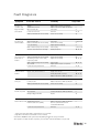
1
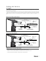
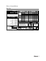
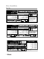
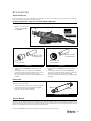
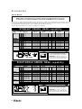
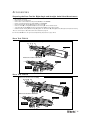
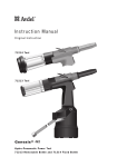
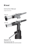
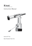
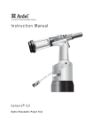
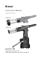
Instruction Manual
Original Instruction
7 1 2 2 4 To o l
7 1 2 2 3 To o l
G3
Genesis ®
H y d ro - P n e u m a t i c P o w e r To o l
71223 Removable Bottle and 71224 Fixed Bottle
Contents
Safety Instructions
4
Specifications
Tool Specification
71223 and 71224 Tool Dimensions
5
5
Intent of Use
Range of Fasteners
Part Numbering
6
6
Putting into Service
Air Supply
71223 Tool Removable Bottle
71224 Tool Fixed Bottle
Adjusting the Vacuum Extraction
Operating Procedure
Removable Stem Collector Bottle 71213-05100
7
7
7
7
8
8
Nose Assemblies
Fitting Instructions
Servicing Instructions
Nose Tips
Type 1
Type 2
Type 4, 5 and 6
9
9
10 - 12
10
11
12
Accessories
Stem Deflector
Preparing the Base Tool for use with Stem Deflector
Extension
Swivel Heads
Straight Swivel Head capability
Right-Angle Swivel Head capability
Preparing the Base Tool for Right-Angle and Straight
Swivel Head Attachment
Base Tool 71223
Base Tool 71224
Swivel Head Fitting Instructions
Swivel Head Servicing Instructions
Constant Components
13
13
13
14
14
14
15
Servicing the Tool
Daily / Weekly
MolyLithium Grease EP 3753 Safety Data
Molykote® 55m Grease Safety Data
Molykote® 111 Grease Safety Data
Service Kit
Maintenance
Nose Equipment
Dismantling the Tool
Head Assembly
Pneumatic Piston Assembly
Air Valve
Rotary Valve
Trigger
Common Parts
General Assembly of Common Parts 71223-02000
and 71224-02000
Parts List for Common Parts 71223-02000
and 71224-02000
18
18
19
19
20
20
20
21
21
22
22
23
23
24
25
Stem Collector Bottles Removable and Fixed
71223 Tool Removable
71224 Tool Fixed
26
26
Priming
Oil Details
Hyspin® VG32 Oil Safety Data
Priming Kit
Priming Procedure
27
27
27
28
Fault Diagnosis
Symptom, Possible Cause and Remedy
29
15
15
16
17
17
LIMITED WARRANTY
Avdel makes the limited warranty that its products will be free of defects in workmanship and materials
which occur under normal operating conditions. This Limited Warranty is contingent upon: (1) the product
being installed, maintained and operated in accordance with product literature and instructions, and (2)
confirmation by Avdel of such defect, upon inspection and testing. Avdel makes the foregoing limited
warranty for a period of twelve (12) months following Avdel’s delivery of the product to the direct purchaser
from Avdel. In the event of any breach of the foregoing warranty, the sole remedy shall be to return the
defective Goods for replacement or refund for the purchase price at Avdel’s option. THE FOREGOING
EXPRESS LIMITED WARRANTY AND REMEDY ARE EXCLUSIVE AND ARE IN LIEU OF ALL OTHER WARRANTIES
AND REMEDIES. ANY IMPLIED WARRANTY AS TO QUALITY, FITNESS FOR PURPOSE, OR MERCHANTABILITY
ARE HEREBY SPECIFICALLY DISCLAIMED AND EXCLUDED BY AVDEL.
Avdel UK Limited policy is one of continuous product development and improvement and we reserve the right to change the specification of any product without prior notice.
3
Safety Instructions
This instruction manual must be read with particular attention to the following safety rules, by any person
installing, operating, or servicing this tool.
1
Do not use outside the design intent.
2
Do not use equipment with this tool/machine other than that recommended and supplied by Avdel UK Limited.
3
Any modification undertaken by the customer to the tool/machine, nose assemblies, accessories or any equipment supplied by Avdel UK
Limited or their representatives, shall be the customer’s entire responsibility. Avdel UK Limited will be pleased to advise upon any
proposed modification.
4
The tool/machine must be maintained in a safe working condition at all times and examined at regular intervals for damage and function
by trained competent personnel. Any dismantling procedure shall be undertaken only by personnel trained in Avdel UK Limited procedures.
Do not dismantle this tool/machine without prior reference to the maintenance instructions. Please contact Avdel UK Limited with your
training requirements.
5
The tool/machine shall at all times be operated in accordance with relevant Health and Safety legislation. In the U.K. the “Health and
Safety at Work etc. Act 1974” applies. Any question regarding the correct operation of the tool/machine and operator safety should be
directed to Avdel UK Limited.
6
The precautions to be observed when using this tool/machine must be explained by the customer to all operators.
7
Always disconnect the air line from the tool/machine inlet before attempting to adjust, fit or remove a nose assembly.
8
Do not operate a tool/machine that is directed towards any person(s) or the operator.
9
Always adopt a firm footing or a stable position before operating the tool/machine.
10 Ensure that vent holes do not become blocked or covered.
11 The operating pressure shall not exceed 7 bar.
12 Do not operate the tool if it is not fitted with a complete nose assembly or swivel head unless specifically instructed otherwise.
13 Care shall be taken to ensure that spent stems are not allowed to create a hazard.
14 If the tool is fitted with a stem collector, it must be emptied when half full.
15 The Tool MUST NOT be operated with the Stem Collector Bottle removed.
16 If the tool is fitted with a stem deflector, it should be rotated until the aperture is facing away from the operator and other person(s)
working in the vicinity.
17 When using the tool, the wearing of safety glasses is required both by the operator and others in the vicinity to protect against fastener
ejection, should a fastener be placed ‘in air’. We recommend wearing gloves if there are sharp edges or corners on the application.
18 Take care to avoid entanglement of loose clothes, ties, long hair, cleaning rags etc. in the moving parts of the tool which should be kept
dry and clean for best possible grip.
19 When carrying the tool from place to place keep hands away from the trigger/lever to avoid inadvertent start up.
20 Excessive contact with hydraulic fluid oil should be avoided. To minimize the possibility of rashes, care should be taken to wash
thoroughly.
21 C.O.S.H.H. data for all hydraulic oils and lubricants is available on request from your tool supplier.
4
Specifications
To o l S p e c i f i c a t i o n
Air Pressure
Minimum - Maximum
Free Air Volume Required
@ 5.5 bar
5-7 bar
4.3 litres
Stroke
Minimum
26 mm
Pull Force
@ 5.5 bar
12.9 kN
Cycle Time
Approximately
1.2 seconds
Noise Level
75 dB(A)
Weight
Including nose equipment
2.25 kg
Vibration
Less than
2.5 m/s2
7 1 2 2 3 a n d 7 1 2 2 4 To o l D i m e n s i o n s
116.0
(7122 0
4 Too
l)
320.00
54.00
DIA
105.0
(7122 0
3 Too
l)
15
DIA
30.00 DIA
127.0
0 (71
223 T
145.0
ool)
0 (71
224 T
ool)
70.00
22.80
DIA
61.00
0.
156.00
00
140.00
128.00 DIA
Dimensions in millimetres
5
Intent of Use
Range of Fasteners
nG3 is a hydro-pneumatic tool designed to place Avdel® breakstem fasteners at high speed making it ideal for batch or flow-line
assembly in a wide variety of applications throughout all industries. It can place all fasteners listed opposite.
The tool features a vacuum system for fastener retention and trouble free collection of the spent stems regardless of tool orientation.
FASTENER
NAME
A complete tool is made up of three
separate elements which will be
supplied individually.
See diagram below.
MM
IN
FASTENER SIZE (
3
3.2 4.0 4.3 4.8
–
1/8 5/32
–
5
3
/16 –
)
5.2
6
6.4 6.5
7
8
9
9.5 10
–
–
1/4
–
–
–
3/8
–
–
AVEX ®
STAVEX ®
AVINOX ® II
AVIBULB ®
NOSE EQUIPMENT MUST BE FITTED
AS DESCRIBED ON PAGE 9.
ETR
BULBEX ®
T- LOK ®
AVDEL ® SR
MONOBOLT ®
INTERLOCK ®
AVTAINER ®
* AVSEAL ® II
Q RIVET
T RIVET
AVDELMATE ®
KLAMP-TITE ®
KLAMPTITE KTR ®
*For Avseal® equipment refer to separate Data Sheet 07900-00840
Part Numbering
1
The part number of the base tool remains the same whichever nose assembly, or nose tip is fitted. See the General Assembly
pages 24-26. If a swivel head is fitted, the same base tool must be adapted. See details page 14.
2
This single nose assembly will allow placing of fasteners by simply selecting the appropriate nose tip from
the range of Type 1 Nose Tips. Other nose assemblies are available for applications with restricted access
and special fasteners. See table pages 11-12. A nose assembly can be substituted by a swivel head (see
pages 14, 15). In this case the nose tip is part of the swivel head.
3
3
The nose tip part number relates to a specific fastener. If access to the application is
restricted, some extended nose tips are available. See table pages 11-12.
NOSE TIP
see note 3
2
1
+
2
+
3
71210-15000
1
=
COMPLETE TOOL
71223-00 . . .
71224-00 . . .
NOSE ASSEMBLY
BASE TOOL
71223-02000
71224-02000
ADD 3 DIGITS FROM THE
*
LAST COLUMN OF A NOSE
n
6
2
TIP TABLE ON PAGES 10 TO 12.
FOR TOOLS WITH SWIVEL
HEADS USE THE TABLES ON
PAGES 14 AND 15.
nn
2
1
*
*
Putting into Service
Air Supply
All tools are operated with compressed air at an optimum pressure of 5.5 bar. We recommend the use of pressure regulators and
filtering systems on the main air supply. These should be fitted within 3 metres of the tool (see diagram below) to ensure maximum
tool life and minimum tool maintenance.
Air supply hoses should have a minimum effective working pressure rating of 150% of the maximum pressure produced in the system
or 10 bar, whichever is the highest. Air hoses should be oil resistant, have an abrasion resistant exterior and should be armoured where
operating conditions may result in hoses being damaged. All air hoses MUST have a minimum bore diameter of 6.4 millimetres or 1/4
inch.
7 1 2 2 3 To o l R e m o v a b l e B o t t l e
STOP COCK
(USED DURING MAINTENANCE
OF FILTER/REGULATOR OR LUBRICATION UNITS)
TAKE OFF POINT
FROM
MAIN SUPPLY
3 METRES MAXIMUM
0 2 4
1416
12
6 8 10
MAIN SUPPLY
DRAIN POINT
G3
PRESSURE REGULATOR
AND FILTER (DRAIN DAILY)
AIR LUBRICATION
PERMISSABLE
7 1 2 2 4 To o l F i x e d B o t t l e
STOP COCK
(USED DURING MAINTENANCE
OF FILTER/REGULATOR OR LUBRICATION UNITS)
TAKE OFF POINT
FROM
MAIN SUPPLY
3 METRES MAXIMUM
0 2 4
1416
12
6 8 10
MAIN SUPPLY
DRAIN POINT
G3
AIR LUBRICATION
PERMISSABLE
PRESSURE REGULATOR
AND FILTER (DRAIN DAILY)
A d j u s t i n g t h e Va c u u m E x t r a c t i o n
•
Using a screwdriver, turn Rotary Valve 38 until the air flow at the rear of the tool ceases.
•
With the nose of the tool pointing downwards, insert a fastener into the nose and hold it into position.
•
Turn the rotary valve either way until there is sufficient suction to retain the fastener.
7
Putting into Service
O p e r a t i n g P ro c e d u r e
•
Ensure that the correct nose assembly suitable for the fastener is fitted.
•
Connect the tool to the air supply.
•
Insert the fastener stem into the nose of the tool. If using a standard nose assembly, the fastener should remain held in by the
vacuum system.
•
Bring the tool with the fastener to the application so that the protruding fastener enters squarely into the hole of the application.
•
Fully actuate the trigger. The tool cycle will broach the fastener and with standard nose assemblies the broken stem will be
projected to the rear of the tool into the collector bottle.
Removable Stem Collector Bottle 71213-05100
•
A quarter turn rotation removes or replaces the collector bottle.
Quarter turn to Assemble
or Remove
Do not use tool when Stem
Collector Bottle is removed
8
Nose Assemblies
Fitting Instructions
I M P O R TA N T
Nose assemblies do NOT include nose tips. Nose tips must be ordered separately.
A complete tool must always be fitted with the correct nose assembly and nose tip for your fastener and must be ordered separately,
refer to the ‘NOSE TIPS’ tables on pages 9 to 11.
If your application presents no access restriction use a Type ‘1’ Nose Tip. If you are placing Avtainer® fasteners a Type 5 Nose Tip
must be used.
Dimensions ‘A’ and ‘B’ in the following Nose Tip tables will help you assess the suitability of a particular nose tip.
You should also check that the dimensions of the nose casing will not restrict access to your application. If access is restricted Type
‘2’ Nose Tips are available for some fasteners. Refer to the table on page 10.
It is essential that nose assembly and nose tip are compatible with the fastener prior to operating the tool.
The Type 4 Nose Tip is an alternative to place 1/4 in Monobolt®. Refer to the table on page 11.
Swivel heads are available as an alternative to nose assemblies as well as an extension when further reach is required.
See pages 12 to 16 in the ‘Accessories’ section.
I M P O R TA N T
The air supply must be disconnected when fitting or removing nose assemblies.
Item numbers in bold refer to nose assembly components in all nose tip tables.
•
Lightly coat Jaws 4 with Moly Lithium grease*.
•
Drop Jaws 4 into Jaw Housing 3 or Chuck Collet 9 depending on which nose assembly you are using.
•
Insert Jaw Spreader 5 into Jaw Housing 3 or insert Front Spring Guide 10 into Chuck Collet 9.
•
Locate Buffer 6 on Jaw Spreader 5.
•
Locate Spring 7 onto Jaw Spreader 5 or onto Front Spring Guide 10.
•
Screw Rear Spring Guide 11 into Chuck Collet 9.
•
Fit Locking Ring 8 onto the Jaw Spreader Housing of the tool.
•
Holding tool pointing down, screw the assembled Jaw Housing 3 or Chuck Collet 9 onto the Jaw Spreader Housing and tighten with
spanner*.
•
Screw the nose tip into Nose Casing 1 and tighten with spanner*.
•
Place Nose Casing 1 over Jaw Housing 3 or Chuck Collet 9 and screw onto the tool, tightening with spanner*.
Servicing Instructions
Nose assemblies should be serviced at weekly intervals. You should hold some stock of all internal components of the nose assembly
and nose tips as they will need regular replacement.
Use Spanner 07900-00849 (supplied with tool) to assist when servicing the nose equipment.
•
Remove the nose equipment using the reverse procedure to the ‘Fitting Instructions’.
•
Any worn or damaged part should be replaced.
•
Clean and check wear on jaws.
•
Ensure that the jaw spreader is not distorted.
•
Check Spring 7 is not distorted.
•
Assemble according to Fitting Instructions above.
* Item included in the nG3 Service Kit. For complete list see page 20.
9
Nose Assemblies
Nose Tips
I M P O R TA N T
Nose assemblies do NOT include nose tips. Nose tips must be ordered separately.
FA S T E N E R
MATERIAL
Ø1
1/8
3.2 Al Alloy
1/8
3.2 Steel
1/8
3.2 Al Alloy
–
3.0 Al Alloy
5 / 32 4.0
Al Alloy
5 / 32 4.0
Steel
5 / 32 4.0
Al Alloy
3 / 16 4.8
Al Alloy
3 / 16 4.8
Al Alloy
Large flange
3 / 16 4.8
Steel
3 / 16 4.8
Al Alloy
1/4
6.4 Al Alloy
MONOBOLT ® 3/16 4.8 Any
5 / 32
BULBEX ®
4.0 Al Alloy
3 / 16
4.8 Al Alloy
1/8
AVINOX ® II
3.2 Stainless Steel
5 / 32
4.0 Stainless Steel
3 / 16 4.8
Stainless Steel
–
T-LOK ®
4.3 Steel
3/ 16
4.8 Steel
1/8
AVIBULB ®
3.2 Steel
5 / 32
4.0 Steel
3 / 16 4.8
Steel
–
6.0 Steel
AVDEL ® SR 1/8 3.2 Any
5 / 32
4.0 Any
3 / 16 4.8
Any
3 / 16 4.8
Any
Countersunk
1/4
6.4 Any
INTERLOCK ® 3/16 4.8 Any
1/8
STAVEX ®
3.2 Steel
5 / 32 4.0
Steel
3 / 16 4.8
Steel
3 / 16 4.8
Steel
Large flange
3 / 16 4.8
Steel
Countersunk
1/8
3.2 Stainless Steel
5 / 32 4.0
Stainless Steel
3 / 16 4.8
Stainless Steel
1
/8
Q RIVET
3.2 Any
5 / 32
4.0 Any
3 / 16 4.8
Any
1/4
6.4 Any
3 / 16 4.8
Any
AVDELMATE®
1/4
6.4 Any
3 / 16 4.8
Any
KLAMPTITE
1/4
KTR ®
6.4 Any
KLAMP-TITE ® 3/16 4.8 Any
1/4
6.4 Any
3 / 16 4.8
Al Alloy
T RIVET
3 / 16 4.8
Al Alloy
Large flange
3 / 16 4.8
Al Alloy/Steel
3 / 16 4.8
Al Alloy/Steel
Large flange
1/4
6.4 Al Alloy
1/4
Large flange
6.4 Al Alloy
1/4
6.4 Al Alloy/Steel
1
/4
Large flange
6.4 Al Alloy/Steel
TYPE 1
NAME
AVEX ®
NOSE TIPS
1 In inches then in millimetres.
2 Head forming nose tips for use with countersunk heads
ONLY.
N O S E A S S E M B LY
part nº 71210-15000
ITEM
DESCRIPTION
PART Nº
NOSE CASING
07340-00306
2
'O' RING
07003-00067
3
JAW HOUSING
07340-00304
4
JAWS
71210-15001
5
JAW SPREADER
07498-04502
6
BUFFER
71210-05001
1
7
SPRING
07500-00418
8
LOCKING RING
07340-00327
NOSE TIP (mm)
PART Nº
'A'
'B'
71210-05002 1 2 . 7 4 . 8
71210-16070 1 2 . 7 3 . 3
07340-06401 2 1 2 . 7 2 . 9
71210-05002 1 2 . 7 4 . 8
71210-16070 1 2 . 7 3 . 3
07381-04701 1 2 . 7 2 . 8
07340-06501 2 1 2 . 7 3 . 3
07381-04701 1 2 . 7 2 . 8
07340-04800 1 9 . 0 3 . 3
07490-04401 1 2 . 7 3 . 3
07340-06601 2 1 2 . 7 4 . 1
07612-02001 1 2 . 7 3 . 3
71210-16020 1 2 . 7 4 . 1
71210-16070 1 2 . 7 3 . 3
07381-04701 1 2 . 7 2 . 8
71210-16070 1 2 . 7 3 . 3
07381-04701 1 2 . 7 2 . 8
07498-01401 1 2 . 7 4 . 8
07340-06201 1 2 . 7 3 . 3
07340-06201 1 2 . 7 3 . 3
71210-16070 1 2 . 7 3 . 3
07381-04701 1 2 . 7 2 . 8
07498-01401 1 2 . 7 4 . 8
07612-02001 1 2 . 7 3 . 3
71210-05002 1 2 . 7 4 . 8
71210-16070 1 2 . 7 3 . 3
07348-07001 1 2 . 7 5 . 7
71210-16050 1 2 . 7 5 . 7
71220-60001 1 2 . 7 3 . 3
07381-04701 1 2 . 7 2 . 8
71210-16070 1 2 . 7 3 . 3
07381-04701 1 2 . 7 2 . 8
07381-04701 1 2 . 7 2 . 8
07340-04800 1 9 . 0 3 . 3
07381-04701 1 2 . 7 2 . 8
71210-16070 1 2 . 7 3 . 3
07381-04701 1 2 . 7 2 . 8
07381-04701 1 2 . 7 2 . 8
71210-05002 1 2 . 7 4 . 8
07340-06201 1 2 . 7 3 . 3
07340-06201 1 2 . 7 3 . 3
07612-02001 1 2 . 7 3 . 3
07340-06201 1 2 . 7 3 . 3
07612-02001 1 2 . 7 3 . 3
71220-16060 1 2 . 7 4 . 8
71220-16061 1 2 . 7 4 . 8
07381-04701 1 2 . 7 2 . 8
07612-02001 1 2 . 7 3 . 3
7 0 3 - A - 2 5 - 6 TA 1 2 . 7 6 . 3 5
12.7 6.35
703-B-21
703-A-25-6T 1 2 . 7 6 . 3 5
12.7 6.35
703-B-26
7 4 3 - A - 2 5 - 8 TA 1 2 . 7 6 . 6 5
12.7 6.65
743-B-21
743-A-25-8T 1 2 . 7 6 . 6 5
12.7 6.65
743-B-26
A
22.9
8
10
7
6
5
4
3
2
1
61
B
see
be lo w
…001
…004
…003
…001
…004
…010
…009
…010
…016
…017
…015
…021
…200
…004
…010
…004
…010
…082
…120
…120
…004
…010
…082
…021
…001
…004
…062
…064
…063
…010
…004
…010
…010
…016
…010
…004
…010
…010
…001
…120
…120
…021
…120
…021
…430
…435
…010
…021
…380
…381
…383
…384
…385
…386
…387
…388
COMPLETE TOOL
PART NUMBER :
precede with
71223-00 or
71224-00
Nose Assemblies
Nose Tips
TYPE 2
NOSE TIPS
N O S E A S S E M B LY
part nº 71210-15200
ITEM
DESCRIPTION
1
NOSE CASING
2
'O' RING
3
JAW HOUSING
4
JAWS
5
JAW SPREADER
6
BUFFER
7
SPRING
8
LOCKING RING
14 JAW SPREADER HOUSING
15
'O' RING
PART Nº
07340-02804
07003-00067
07340-00304
71210-15001
07498-04502
71210-05001
07500-00418
07340-00327
71210-02101
07003-00277
FA S T E N E R
MATERIAL
Ø1
1/8
3.2 Aluminium Alloy
1/8
3.2 Steel
5 / 32 4.0
Aluminium Alloy
5 / 32 4.0
Steel
3 / 16 4.8
Aluminium Alloy
3 / 16 4.8
Steel
BULBEX ® 5/32 4.0 Aluminium Alloy
3 / 16
4.8 Aluminium Alloy
–
T-LOK ®
4.3 Steel
3 / 16 4.8
Steel
1/8
STAVEX ®
3.2 Steel
5 / 32 4.0
Steel
3 / 16 4.8
Steel
1/8
3.2 Stainless Steel
5 / 32 4.0
Stainless Steel
3 / 16 4.8
Stainless Steel
AVIBULB ® 1/8 3.2 Steel
5 / 32 4.0
Steel
–
E.T.R
5.2 Steel/Brass
NAME
AVEX ®
1
NOSE TIP (mm)
PART Nº
'A'
'B'
0 7 3 4 0 -0 2 8 0 5 9 . 5 1 2 . 9 5
0 7 3 4 0 -0 2 8 0 6 9 . 5 1 1 . 4
0 7 3 4 0 -0 2 8 0 6 9 . 5 1 1 . 4
0 7 3 4 0 -0 2 8 0 7 1 2 . 7 1 0 . 0
0 7 3 4 0 -0 2 8 0 7 1 2 . 7 1 0 . 0
0 7 3 4 0 -0 7 3 0 1 1 2 . 7 1 1 . 8
0 7 3 4 0 -0 2 8 0 6 9 . 5 1 1 . 4
0 7 3 4 0 -0 2 8 0 7 1 2 . 7 1 0 . 0
0 7 2 4 1 -0 7 1 0 1 1 2 . 7 1 0 . 0
0 7 2 4 1 -0 7 1 0 1 1 2 . 7 1 0 . 0
0 7 3 4 0 -0 2 8 0 6 9 . 5 1 1 . 4
0 7 3 4 0 -0 2 8 0 7 1 2 . 7 1 0 . 0
0 7 3 4 0 -0 2 8 0 7 1 2 . 7 1 0 . 0
0 7 3 4 0 -0 2 8 0 6 9 . 5 1 1 . 4
0 7 3 4 0 -0 2 8 0 7 1 2 . 7 1 0 . 0
0 7 3 4 0 -0 2 8 0 7 1 2 . 7 1 0 . 0
0 7 3 4 0 -0 2 8 0 6 9 . 5 1 1 . 4
0 7 3 4 0 -0 2 8 0 7 1 2 . 7 1 0 . 0
0 7 3 4 0 -0 2 8 0 7 1 2 . 7 1 0 . 0
s ee
b el o w
…002
…008
…008
…014
…014
…018
…008
…014
…121
…121
…008
…014
…014
…008
…014
…014
…008
…014
…014
In inches then in millimetres.
TYPE 2 NOSE TIPS ARE EXTENDED
TO ALLOW ACCESS INTO
APPLICATIONS WHERE TYPE 1
NOSE TIPS WILL NOT REACH.
COMPLETE TOOL
PART NUMBER :
precede with
71223-00 or
71224-00
A
B
22.9
14 15
8
7
6 5 4
3
2
1
58.3
Note: Items 14 and 15 are not required when assembling a Type 2 Nose Tip to the Base Tool nG3 (71223-02000 or 71224-02000).
11
Nose Assemblies
Nose Tips
TYPE 4
NAME
MONOBOLT ®
NOSE TIP
FA S T E N E R
MATERIAL
Ø1
1/4
6.4 Any
NOSE TIP (mm)
see
PART Nº
'A'
'B' b el o w
7 1 2 2 0 -1 6 0 2 1 1 4 . 3 4 . 1 … 2 0 2
1 In inches then in millimetres
A
N O S E A S S E M B LY part nº 71220-15400
DESCRIPTION
NOSE CASING
'O' RING
CHUCK COLLET
JAWS
PART Nº
07498-00501
07003-00067
07498-00502
07497-03002
ITEM
10
7
11
8
DESCRIPTION
FRONT SPRING GUIDE
SPRING
REAR SPRING GUIDE
LOCKING RING
PART Nº
07498-00507
07500-02005
07498-00503
07340-00327
B
FITTED TO THIS LONG NOSE
ASSEMBLY, THE TYPE 4 NOSE TIP
WILL ALLOW THE PLACING OF
1 /4 " MONOBOLT ® FASTENERS
20.6
ITEM
1
2
9
4
8
11
7 10
4
9
TYPE 5
NAME
AVTAINER ®
NOSE TIP
IN APPLICATIONS REQUIRING
VERY DEEP ACCESS.
98.5
1
2
FA S T E N E R
MATERIAL
Ø1
3/8
9.6 Steel
NOSE TIP (mm)
see
PART Nº
'A'
'B' b el o w
0 7 4 9 8 -0 0 8 0 2 1 9 . 1 4 . 1 … 2 4 3
1 In inches then in millimetres
A
N O S E A S S E M B LY part nº 71220-15500
PART Nº
07498-00501
07003-00067
07498-00801
07220-02302
07498-00803
ITEM
DESCRIPTION
7
SPRING
11
REAR SPRING GUIDE
8
LOCKING RING
12
SIDE EJECTION ADAPTOR
13 VAC SHUT-OFF STOP NUT ASSY
PART Nº
07500-02005
07498-00503
07340-00327
07498-00900
71233-20200
B
THERE IS ONLY ONE TYPE 5 NOSE
TIP, SPECIFICALLY DESIGNED TO
PLACE AVTAINER ® FASTENERS WITH
THIS SPECIAL NOSE ASSEMBLY.
20.6
DESCRIPTION
NOSE CASING
'O' RING
CHUCK COLLET
JAWS
FRONT SPRING GUIDE
COMPLETE TOOL
PART NUMBER :
precede with
71223-00 or 71224-00
28.6
ITEM
1
2
9
4
10
COMPLETE TOOL
PART NUMBER :
precede with
71223-00 or 71224-00
13
90
12
8
11
TYPE 6
NOSE TIPS
NAME
MONOBOLT ®
INTERLOCK®
STAVEX ®
FA S T E N E R
Ø1
1/4
6.4
1/4
6.4
1/4
6.4
7
A
B
NOSE
PART Nº
71220 -1 6 0 2 1
07612 -0 2 0 0 1
07612 -0 2 0 0 1
MATERIAL
Any
Any
Any
10
4
9
COMPLETE TOOL
PART NUMBER
PRECEDED WITH:
71223-00 or 71224-00
TIP (mm)
'A'
'B'
14.3 4.1
14.3 3.6
14.3 3.6
see
above
... 201
... 261
... 261
2
98.5
1
N O S E A S S E M B LY
part nº 71230-15800
ITEM
1
2
3
4
5
6
7
8
DESCRIPTION
NOSE CASING
'O' RING
JAW HOUSING
JAWS
JAW SPREADER
BUFFER
SPRING
LOCKING RING
22.9
8
12
7
6
5
4
3
2
1
61
1 In inches then in millimetres
PART Nº
07340-00306
07003-00067
07612-02003
07612-02002
07498-04502
07498-03003
07500-00418
07340-00327
Accessories
Stem Deflector
The stem deflector is a very simple alternative to the standard stem collector and allows access in restricted areas. To replace the
stem collector with the stem deflector proceed as follows:
Preparing the Base Tool for use with Stem Deflector
The airline must be diconnected before any servicing or dismantling.
•
Remove stem collector bottle
assembly 71213-05100 or
71210-20400.
41
40
71213-20103
or
71210-20101
ADAPTOR
07340-00342
STEM DEFLECTOR
36
STEM DEFLECTOR
07340-00342
STEM DEFLECTOR
07340-00342
ADAPTOR
71213-20103
ADAPTOR NUT
71210-20101
71223 Tool
•
•
•
•
Fit Stem Deflector (07340-00342) into Adaptor (7121320103).
Screw Adaptor onto End Cap Assembly 71213-05103.
Rotate the stem deflector until the aperture faces away from
the operator and any other person(s) in the vicinity.
Turn off air supply to the vacuum system by adjusting Rotary
Valve 38.
71224 Tool
•
•
•
•
Fit Stem Deflector (07340-00342) into Adaptor (7121020101).
Screw Adaptor onto End Cap Assembly 71403-02102.
Rotate the stem deflector until the aperture faces away from
the operator and any other person(s) in the vicinity.
Turn off air supply to the vacuum system by adjusting Rotary
Valve 38.
Extension
Fitted between the tool and the nose assembly the extension
allows access into deep channels.
•
•
•
•
To fit the extension, remove any nose assembly components.
Screw the inner extension to Jaw Spreader Housing 41.
Screw the outer onto Head Assembly 58.
Fit the nose assembly onto the extension.
INNER
OUTER
EXTENSION 71210-20300
Swivel Heads
Instead of a nose assembly, a swivel head can be fitted to a base tool. It allows 360° rotation of the tool about the nose tip and allows
access into many applications otherwise too restrictive. There are two types of swivel heads: the straight swivel head with the nose tip
slightly offset from the centre line of the tool head and the right-angle swivel head with the nose tip on a perpendicular axis to the head
of the tool. See drawings below for dimensions and pages 15-16 for detail.
Item numbers in bold refer to the general assembly drawing and parts list on pages 24 and 25.
13
Accessories
Swivel Heads
I M P O R TA N T
PRIOR to fitting a swivel head, the base tool must be adapted. See Preparing the Base Tool opposite.
In contrast to nose assemblies part numbers of swivel heads do INCLUDE a nose tip as shown below.
Swivel heads are supplied separately for fitting to a base tool forming a complete tool. See table below for part numbers. Jaws and
nose tips vary depending on the fastener to be placed but all other components remain the same within each type of swivel head. See
the ‘capability’ tables below and page 15. For the ‘Constant Components’ table see page 17.
'A’ and ‘B’ dimensions will help you assess the accessibility of your application.
STRAIGHT SWIVEL HEAD capability
FA S T E N E R
MATERIAL
Ø1
1 / 8 3.2 Al Alloy
1 / 8 3.2 Steel
5 / 32 4.0 Al Alloy
5 / 32 4.0 Steel
3 / 16 4.8 Al Alloy
5 / 32 4.0 Al Alloy
BULBEX ®
3 / 16 4.8 Al Alloy
AVINOX ® II 1/8 3.2 Stainless Steel
5 / 32 4.0 Stainless Steel
– 4.0 Al Alloy
AVSEAL ® II
– 4.0 Al Alloy
– 5.0 Al Alloy
– 5.0 Al Alloy
1 / 8 3.2 Steel
STAVEX ®
5 / 32 4.0 Steel
1 / 8 3.2 Stainless Steel
5 / 32 4.0 Stainless Steel
SWIVEL HEAD
PART Nº
07345 -0 3 0 0 0
07345 -0 3 1 0 0
07345 -0 3 1 0 0
07345 -0 3 2 0 0
07345 -0 3 2 0 0
07345 -0 3 1 0 0
07345 -0 3 2 0 0
07345 -0 3 1 0 0
07345 -0 3 2 0 0
71213 -0 6 0 0 0
71213 -0 6 6 0 0
71213 -0 6 1 0 0
71213 -0 6 7 0 0
07345 -0 3 1 0 0
07345 -0 3 2 0 0
07345 -0 3 1 0 0
07345 -0 3 2 0 0
NAME
AVEX ®
56
92
NOSE TIP (mm)
PART Nº
'A'
0 7 3 4 5 -0 3 6 0 0
7.87
0 7 3 4 5 -0 3 7 0 0
7.87
0 7 3 4 5 -0 3 7 0 0
7.87
0 7 3 4 5 -0 3 8 0 0
7.87
0 7 3 4 5 -0 3 8 0 0
7.87
0 7 3 4 5 -0 3 7 0 0
7.87
0 7 3 4 5 -0 3 8 0 0
7.87
0 7 3 4 5 -0 3 7 0 0
7.87
0 7 3 4 5 -0 3 8 0 0
7.87
7 1 2 1 3 -1 6 4 0 1
6.35
2
6.35
7 1 2 1 3 -1 6 4 0 2
7.62
7 1 2 1 3 -1 6 4 0 3
2
7.62
7 1 2 1 3 -1 6 4 0 4
7.87
0 7 3 4 5 -0 3 7 0 0
7.87
0 7 3 4 5 -0 3 8 0 0
7.87
0 7 3 4 5 -0 3 7 0 0
7.87
0 7 3 4 5 -0 3 8 0 0
A
20
'B'
3.81
3.81
3.81
3.81
3.81
3.81
3.81
3.81
3.81
1.95
4.11
2.00
4.11
3.81
3.81
3.81
3.81
JAWS
PART Nº
0 7 3 4 0 -0 0 2 1 3
0 7 3 4 0 -0 0 2 1 3
0 7 3 4 0 -0 0 2 1 3
0 7 4 9 0 -0 4 6 0 2
0 7 4 9 0 -0 4 6 0 2
0 7 3 4 0 -0 0 2 1 3
0 7 4 9 0 -0 4 6 0 2
0 7 3 4 0 -0 0 2 1 3
0 7 4 9 0 -0 4 6 0 2
0 7 3 4 0 -0 0 2 1 3
0 7 3 4 0 -0 0 2 1 3
0 7 3 4 0 -0 0 2 1 3
0 7 3 4 0 -0 0 2 1 3
0 7 3 4 0 -0 0 2 1 3
0 7 4 9 0 -0 4 6 0 2
0 7 3 4 0 -0 0 2 1 3
0 7 4 9 0 -0 4 6 0 2
s ee
b el o w
…001
…004
…004
…010
…010
…004
…010
…004
…010
…160
…180
…161
…181
…004
…010
…004
…010
COMPLETE TOOL PART NUMBER :
precede with 71223-30 or 71224-30
(the stop nut and safety cap are included)
6
360 o rotation
1
2
In inches then in millimetres.
IMPORTANT: in contrast to complete tools
with nose assemblies, those fitted with swivel heads
include the nose tip as a part of the head.
B
Long nose tip for deep placing.
R I G H T- A N G L E S W I V E L H E A D c a p a b i l i t y
FASTENER
MATERIAL
Ø1
1 / 8 3.2 Aluminium Alloy
1 / 8 3.2 Steel
5 / 32 4.0 Aluminium Alloy
5 / 32 4.0 Steel
3 / 16 4.8 Aluminium Alloy
5 / 32 4.0 Aluminium Alloy
BULBEX®
3 / 16 4.8 Aluminium Alloy
1 / 8 3.2 Stainless Steel
AVINOX ® II
5 / 32 4.0 Stainless Steel
– 4.0 Aluminium Alloy
AVSEAL ® II
– 4.0 Aluminium Alloy
– 5.0 Aluminium Alloy
– 5.0 Aluminium Alloy
1
/ 8 3.2 Steel
STAVEX ®
5 / 32 4.0 Steel
1 / 8 3.2 Stainless Steel
5 / 32 4.0 Stainless Steel
NAME
AVEX ®
SWIVEL HEAD
PART Nº
07346-03000
07346-03100
07346-03100
07346-03200
07346-03200
07346-03100
07346-03200
07346-03100
07346-03200
71213-04000
71213-04700
71213-04100
71213-04800
07346-03100
07346-03200
07346-03100
07346-03200
NOSE TIP (mm)
'A'
PART Nº
07345-03600
7.87
07345-03700
7.87
07345-03700
7.87
07345-03800
7.87
07345-03800
7.87
07345-03700
7.87
07345-03800
7.87
07345-03700
7.87
07345-03800
7.87
71213-16401
6.35
2
71213-16402
6.35
71213-16403
7.62
2
71213-16404
7.62
7.87
07345-03700
7.87
07345-03800
7.87
07345-03700
7.87
07345-03800
97
74
7.6
56
52
32
A
20
B
360
1
14
In inches then in millimetres.
o
rotation
2
Long nose tip for deep placing.
'B'
3.81
3.81
3.81
3.81
3.81
3.81
3.81
3.81
3.81
1.95
4.11
2.00
4.11
3.81
3.81
3.81
3.81
JAWS
PART Nº
07340-00213
07340-00213
07340-00213
07490-04602
07490-04602
07340-00213
07490-04602
07340-00213
07490-04602
07340-00213
07340-00213
07340-00213
07340-00213
07340-00213
07490-04602
07340-00213
07490-04602
see
below
…001
…004
…004
…010
…010
…004
…010
…004
…010
…160
…180
…161
…181
…004
…010
…004
…010
COMPLETE TOOL PART NUMBER :
precede with 71223-40 or 71224-40
(the stop nut and safety cap are included)
IMPORTANT: in contrast to complete tools
with nose assemblies, those fitted with swivel
heads include the nose tip as a part of the head.
Accessories
Preparing the Base Tool for Right-Angle and Straight Swivel Head A t t a c h m e n t
•
•
•
•
•
•
•
•
Disconnect the air supply.
Remove any nose assembly items.
Remove Stem Collector Bottle Assembly (71213-05100) or 71210-20400.
Replace assembly with Safety Cap (71213-20102 or 71210-20101).
Unscrew Jaw Spreader Housing 41 and remove with ‘O’ Ring 12
Remove Locknut 40, ‘O’ Rings 15 and 19, and Seal Housing 52. Do not refit these items.
Screw Stop Nut (71213-20200) onto the front of Head Piston 36 as far as it will go by hand.
Refit Jaw Spreader Housing 41 and ‘O’ Ring 12, tighten onto Head Piston 36, finally tighten Stop Nut against Jaw Spreader Housing.
The tool is now ready to be fitted with a swivel head. Instructions page 16.
Item numbers in bold refer to the general assembly drawing and parts list on pages 24-25.
B a s e To o l 7 1 2 2 3
Base tool to receive a nose assembly
41
12 40
52
71210-05100
19
15
36
Base tool to receive a swivel head
71213-20102
SAFETY CAP
71213-20200
STOP NUT
B a s e To o l 7 1 2 2 4
Base tool to receive a nose assembly
41 12 40
52
71210-20400
19
15
36
Base tool to receive a swivel head
71210-20201
SAFETY CAP
71213-20202
STOP NUT
15
Accessories
The fitting and servicing procedures for both types of head are almost identical. Differences are clearly indicated.
I M P O R TA N T
PRIOR to fitting a swivel head, the base tool must be adapted. See Preparing the Base Tool opposite.
The air supply must be disconnected when fitting or removing swivel heads.
Swivel Head Fitting Instructions
The following procedure will allow you to assemble and fit either of the swivel heads to the tool. If you order a complete swivel head
rather than individual components, you will only need to start at stage ‘L’.
All moving parts should be lubricated. Unless stated otherwise use MolyLithium grease (details page 18).
When on grey tint, instructions refer only to the right-angle swivel head. Item numbers in bold refer to illustrations below.
1
18
17
16
3
20
19
A
Fit Locking Ring 10 over Jaw Spreader Housing 41*
(71210-02102). *See page 15.
B
Coat Screw 13 with thread locking adhesive and use to
secure Nose Tip 14 onto Body 5.
C
Lightly lubricate items 17, 18, 19, 20 and insert into
Jaw Carrier 3 as shown. Secure with Screws 16.
D
Position Lever 4 into Body 5 and hold in place with pin
15 through the hole of Body 5 (not a slot).
E
Lubricate the sides of the Jaw Carrier Assembly and
insert into Body 5.
F
Lubricate Rollers 8 and ENSURE that they will freely
rotate in the holes of Adaptor 9. If necessary ream the
holes.
G
Position Spring Clip 7 over Adaptor 9 past the holes for
the rollers and rotate until the locating peg is aligned
with the corresponding hole in Adaptor 9 (smallest
hole).
H
Fit Adaptor 9 over the end of Body 5 and drop Rollers 8
into place. Push Spring Clip 7 over Rollers 8.
I
Insert Spindle 11 through Adaptor 9 into Jaw Carrier 3
until the hole lines up with slot in Body 5. Temporarily
hold in place with Pin 6.
J
Insert Pin 12 through the front slot of Body 5 into Jaw
Carrier 3.
K
Hold the assembly vertical to prevent all pins dropping
out and slide the jaw carrier assembly back and forth a
few times to ensure free movement. Go to M.
L
Remove Screws 23 (4 off) and Guard 1. On a straight
swivel head also remove Screw 21 and Platform 22.
16
5
14
13
6
12
21
10
8
7
22
11
8
9
8
STRAIGHT SWIVEL HEAD
18
23 17
19
20
15
1
16
2
11
16
4
3
14
N
Screw the assembly over Spindle 11 onto the tool
handle. Replace Pin(s) 6.
O
On straight swivel heads attach Platform 22 onto the
top of the Spindle 11 with Screw 21. Deburr the back
end of Platform 22 so that it cannot catch on Guard 1.
P
Snap Guard 1 over the assembly, align screw holes in
guard with tapped holes in body assembly.
Q
Insert Pivot Pin 15 through slots in guard and hole in
body. Fit Circlip 2 onto pivot pin so that the circlip seats
in groove provided.
R
Coat the thread of Screws 23 (4 off) with thread locking
adhesive and screw into body assembly securing guard
to body assembly.
7
6
8
6
13
M Push Pin(s) 6 out and let Spindle 11 drop out. Screw
Spindle 11 onto the Jaw Spreader Housing of the tool,
leaving the small screw fixing hole uppermost for
straight swivel. Tighten gently with a tommy bar.
12
5
9
8
10
RIGHT-ANGLE SWIVEL HEAD
16
Accessories
Swivel Head Servicing Instructions
Swivel heads should be serviced at weekly intervals.
•
Remove the complete head using the reverse procedure to
the ‘Fitting instructions’ omitting step ‘L’.
17
•
If Guard 1 is at all damaged it must be replaced by a new
one.
•
Any worn or damaged parts should be replaced.
•
Pay particular attention to jaw carrier items in the upper
illustration opposite as follows:
Check wear on Jaws 17.
Check that Jaw Spreader Tube 18 is not distorted.
Check that Spring 19 is neither broken or distorted.
Check that Spring Guide 20 is not damaged.
•
Check that Spring clip 7 is not distorted. When removing
Spring Clip 7, use two screwdrivers as shown in the lower
illustration opposite.
•
Check for excessive wear on slots of Body 5.
•
Assemble according to fitting instructions.
18
20
19
7
5
Item numbers in bold refer to Swivel Head illustrations on
this page. Guard 1 refers to illustration on page 16.
While nose tips and jaws will vary for each swivel head, other components remain constant within each type of head. See table below.
For nose tips and jaws part numbers see within the tables on pages 10, 11 and 12.
C O N S TA N T C O M P O N E N T S
ITEM
1
2
3
4
5
6
7
8
9
10
11
12
13
15
16
18
19
20
21
22
23
DESCRIPTION
GUARD
CIRCLIP
JAW CARRIER
LEVER
BODY
PIVOT PIN
SPRING CLIP
ROLLER
ADAPTOR
LOCKING RING
SPINDLE
DOWEL PIN
SCREW
PIVOT PIN
SCREW
JAW SPREADER
SPRING
SPRING GUIDE
SCREW
PLATFORM
SCREW
STRAIGHT SWIVEL
RIGHT-ANGLE SWIVEL
07494-05000
07494-03026
07494-03015
07343-02207
07495-03900
07007-00039
07345-03001
07345-03003
07345-03002
07007-00038
07342-02207
07494-03028
07346-03101
07165-00305
07494-03027
07001-00368
07345-00401
-
07495-03003
07004-00105
07494-03026
07495-03004
07495-03002
07343-02207
07495-03900
07007-00039
07345-03001
07345-03003
07345-03002
07007-00038
07342-02207
07346-03102
07494-03028
07346-03101
07165-00305
07494-03027
–
–
07210-00804
17
S e r v i c i n g t h e To o l
I M P O R TA N T
Read Safety Instructions on page 4.
The employer is responsible for ensuring that tool maintenance instructions are given to the appropriate personnel.
The operator should not be involved in maintenance or repair of the tool unless properly trained.
The tool shall be examined regularly for damage and malfunction.
Daily
•
Check for air leaks. If damaged, hoses and couplings should be replaced.
•
If there is no filter on the pressure regulator, bleed the air line to clear it of accumulated dirt or water before connecting the air hose
to the tool. If there is a filter, drain it.
•
Check that the nose assembly or swivel head is correct for the fastener to be placed.
•
Check the stroke of the tool meets the minimum specification (page 5). The last step of the Priming Procedure on page 28 explains
how to measure the stroke.
•
Either a stem collector or a stem deflector must be fitted to the tool unless using a swivel head is fitted.
•
Check that Base Cover 31 is fully tightened onto Body 30.
We e k l y
•
Dismantle and clean the nose assembly with special attention to the jaws. Lubricate with MolyLithium grease before assembling.
•
Check for oil leaks and air leaks in the air supply hose and fittings.
MolyLithium Grease EP 3753 Safety Data
Grease can be ordered as a single item, the part number is shown in the Service Kit page 20.
First Aid
SKIN:
As the grease is completely water resistant it is best removed with an approved emulsifying skin cleaner.
INGESTION:
Ensure the individual drinks 30ml Milk of Magnesia, preferably in a cup of milk.
EYES:
Irritant but not harmful. Irrigate with water and seek medical attention.
Fire
FLASH POINT: Above 220°C.
Not classified as flammable.
Suitable extinguishing media: CO2, Halon or water spray if applied by an experienced operator.
Environment
Scrape up for incineration or disposal on approved site.
Handling
Use barrier cream or oil resistant gloves
Storage
Away from heat and oxidising agent.
Item numbers in bold refer to the general assembly drawing and parts list on pages 24-25.
18
S e r v i c i n g t h e To o l
Molykote® 55m Grease Safety Data
First Aid
SKIN:
Flush with water. Wipe off.
INGESTION:
No first aid should be needed.
EYES:
Flush with water.
Fire
FLASH POINT: Above 101.1°C. (closed cup)
Explosive Properties: No
Suitable Extinguishing Media: Carbon Dioxide Foam, Dry Powder or fine water spray.
Water can be used to cool fire exposed containers.
Environment
Do not allow large quantities to enter drains or surface waters.
Methods for cleaning up: Scrape up and place in suitable container fitted with a lid. The spilled product produces an extremely
slippery surface.
Harmful to aquatic organisms and may cause long-term adverse effects in the aquatic environment. However, due to the physical
form and water - insolubility of the product the bioavailability is negligible.
Handling
General ventilation is recommended. Avoid skin and eye contact.
Storage
Do not store with oxidizing agents. Keep container closed and store away from water or moisture.
Molykote® 111 Grease Safety Data
First Aid
SKIN:
No first aid should be needed.
INGESTION:
No first aid should be needed.
EYES:
No first aid should be needed.
INHALATION:
No first aid should be needed.
Fire
FLASH POINT: Above 101.1°C. (closed cup)
Explosive Properties: No
Suitable Extinguishing Media: Carbon Dioxide Foam, Dry Powder or fine water spray.
Water can be used to cool fire exposed containers.
Environment
No adverse effects are predicted.
Handling
General ventilation is recommended. Avoid eye contact.
Storage
Do not store with oxidizing agents. Keep container closed and store away from water or moisture.
19
S e r v i c i n g t h e To o l
Service Kit
For an easy complete service, Avdel offers the complete service kit below.
SERVICE KIT : 71210-99990
PART Nº
07900-00667
07900-00692
07900-00670
07900-00672
07900-00706
07900-00684
07900-00685
07900-00351
07900-00469
07900-00158
07900-00224
07900-00734
07900-00164
Spanners are specified in inches and across flats unless otherwise stated
DESCRIPTION
PISTON SLEEVE
TRIGGER VALVE EXTRACTOR
BULLET
'T' SPANNER
LOCATION SPIGOT
GUIDE TUBE
INSERTION ROD
3 MM ALLEN KEY
2.5 MM ALLEN KEY
2 MM PIN PUNCH
4 MM ALLEN KEY
STOP NUT - MAXLOK ®
CIRCLIP PLIERS
PART Nº
DESCRIPTION ®
07900-00008 7/16" x1/2" SPANNER
07900-00012 9/16" x5/8" SPANNER
07900-00015 5/8" x 11/16" SPANNER
07900-00686 PEG SPANNER
07900-00677 SEAL EXTRACTOR
07900-00698 STOP NUT
07900-00700 PRIMING PUMP
07992-00020 GREASE - MOLY LITHIUM E.P.3753
07992-00075 GREASE - MOLYKOTE ® 55M
07900-00755 GREASE - MOLYKOTE ® 111
07900-00850 PIN SPANNER
07900-00898 ROTARY VALVE HOOK
Maintenance
(Annually or every 500,000 cycles whichever is the soonest)
Annually or every 500,000 cycles the tool should be completely dismantled and new components should be used where worn, damaged
or recommended. All ‘O’ rings and seals should be renewed and lubricated with Molykote® 55m grease for pneumatic sealing or
Molykote® 111 for hydraulic sealing.
I M P O R TA N T
Read Safety Instructions on page 4.
The employer is responsible for ensuring that tool maintenance instructions are given to the appropriate personnel.
The operator should not be involved in maintenance or repair of the tool unless properly trained.
The tool shall be examined regularly for damage and malfunction.
The air line must be disconnected before any servicing or dismantling is attempted unless specifically instructed otherwise.
It is recommended that any dismantling operation be carried out in clean conditions.
Before proceeding with dismantling, empty the oil from the tool following the first four steps of the ‘Priming Procedure’ on page 28.
Prior to dismantling the tool it is necessary to remove the nose equipment. For instructions see the nose assemblies section, pages 10 to
12 or if a swivel head was fitted pages 14 to 16.
For a complete service of the tool, we advise that you proceed with dismantling of sub-assemblies in the order shown.
After any dismantling REMEMBER to prime the tool and to fit an appropriate nose assembly or swivel head.
Nose Equipment
•
Unscrew Nose Casing 1 and Nose Tip.
•
Unscrew Jaw Housing 3 and remove Jaws 4, Jaw Spreader 5, Spring 7 and Buffer 6.
•
Inspect all components. Renew all damaged or worn parts.
•
Clean all parts and apply MolyLithium Grease EP 3753 (07992-00020) to taper bore of Jaw Housing.
•
Reassemble in reverse order to above.
Item numbers in bold refer to Nose Tip Table on page 10.
20
S e r v i c i n g t h e To o l
D i s m a n t l i n g t h e To o l
Before dismantling the tool the oil must be emptied from it.
•
With the air supply switched OFF at ON/OFF Valve Assembly 62 remove Bleed Screw 1 and Bonded Seal 6.
•
Insert tool over a suitable container, switch air supply ON and actuate tool.
•
Oil will expel from bleed screw orifice into container.
•
Switch air supply OFF after all oil is expelled.
Ensure the bleed screw orifice is facing away from the person performing this operation.
Head Assembly
71223 Tool with Removable Stem Collector Bottle
•
Quarter turn and pull off Stem Collector Bottle Assembly 9. See illustration on page 8.
•
Unscrew retaining Nut 8 together with Deflector 7.
•
Pull off Bottle Adaptor Assembly 6.
•
Unscrew End Cap Assembly 4 together with ‘O’ Rings 2, 3 and Lip Seal 1.
or
71224 Tool with Fixed Stem Collector Bottle
•
Rotate the Stem Collector Outer so that the aperture in the stem Collector Body is fully exposed.
•
Unscrew the Retaining Nut 3.
•
Remove the Bottle Assembly 4.
•
Remove the Bottle Adaptor Assembly 8.
•
Unscrew and remove the End Cap Assembly 2 together with Lip Seal 1, ‘O’ Ring 7 and Seal 6 .
Item numbers in bold above refer to the Stem Collector Bottles Removable and Fixed on page 26.
then
•
Remove Spring 91.
•
Loosen Locknut 40 with a spanner* and unscrew Jaw Spreader Housing 41 together with ‘O’ Ring 12.
•
Withdraw Vacuum Sleeve 42.
•
Remove Locknut 40 together with ‘O’ Rings 19 and 15.
•
Push Head Piston 36 to the rear and out of Head Assembly 58 taking care not to damage the cylinder bore.
•
Using circlip pliers* remove Seal Retainer 43. Push Lip Seal 8 and Bearing Tape 26 to the rear and out of Head Assembly 58 taking
care not to damage the cylinder bore.
•
Remove Seal Housing 52 and Lip Seal 2.
Assemble in reverse order noting the following points:
•
Place Lip Seal 8 onto the insertion rod* ensuring correct orientation. Locate the guide tube* into the head of the tool and push the
insertion rod* with the seal in place through the guide tube*. Pull the insertion rod* out and then the guide tube*.
•
The chamfered edge of Seal Retainer 43 must face forward with the gap at the bottom.
•
After fitting Lip Seals 11 ‘O’ Rings 18 (x2) and Bearing Tape 27 onto the Head Piston 36 ensuring correct orientation, lubricate the
cylinder bore and place the piston sleeve* into the back of Head Assembly 58. Slide the bullet* onto the threaded part of Head Piston
36 and push the piston with the seals through the piston sleeve* as far as it will go. Slide the bullet* off the piston and remove piston
sleeve*.
•
Jaw Spreader Housing 41 must be fully tightened onto Head Piston 36 before tightening Locknut 40 against it.
•
Reprime in accordance with the instructions on page 28.
* Item included in the nG3 Service Kit. For complete list see page 20.
Item numbers in bold refer to the General Assembly and Parts List of Common parts on pages 24 and 25.
21
S e r v i c i n g t h e To o l
Pneumatic Piston Assembly
•
Remove ‘ON/OFF’ Valve Assembly 62.
•
Clamp the body of the inverted tool ACROSS THE AIR INLET BOSSES in a vice fitted with soft jaws.
•
Pull off Rubber Boot 48.
•
Using the peg spanner* unscrew Base Cover 31.
•
Unscrew Nyloc Nuts 67 (2 off) and remove Base Plate Assembly 65.
•
Remove Cylinder Liner 37 together with Sealing Washers 29 (2 off) and ‘O’ Rings 66 (2 off).
•
Remove Pneumatic Piston Assembly 57 together with ‘O’ Ring 75, Lip Seal 90 (3 off) and Guide Ring 51.
•
Engage the Seal Extractor* into Seal Assembly 60 and withdraw Seal Assembly from intensifier tube of the Head Assembly 58.
Assemble in reverse order to dismantling.
•
Seals should be checked for damage and replaced as necessary. Lubricate pneumatic seals with Molykote® 55m and hydraulic seals with
Molykote® 111.
A i r Va l v e
Dismantling
•
Remove Pneumatic Piston Assembly 57 as described above in Pneumatic Piston Assembly.
•
Using Spanner (07900-00672), and Location Spigot Assembly (07900-00706). Unscrew Clamp Nut 39 and remove together with Top
Plate Assembly 44 together with Tie Rods 56, Transfer Tube Assembly 61, ‘O’ Rings 14 and Silencer Pads 53.
•
Remove tool from vice and separate Body 30 from Handle 64. Remove ‘O’ Ring 17.
•
Push out the Valve Seat 34, from the Body 30, together with ‘O’ Rings 14.
•
Pull out Valve Spool Assembly 59 from Handle 64. Remove ‘O’ Ring 7 from handle counterbore.
Assembly
Assemble in reverse order to Dismantling Instructions
•
Seals should be checked for damage and replaced if necessary, lubricated with Molykote® 55m grease.
•
Apply Loctite® 243 to Clamp Nut 39 and tighten to torque 11ftlb (14.91 Nm).
I M P O R TA N T
Check the tool against daily and weekly servicing.
Priming is ALWAYS necessary after the tool has been dismantled and prior to operating.
* Item included in the nG3 Service Kit. For complete list see page 20.
Item numbers in bold refer to the general assembly drawing and parts list on pages 24 and 25.
22
S e r v i c i n g t h e To o l
R o t a r y Va l v e
Dismantling
•
Remove Pneumatic Piston Assembly 57 as described in Pneumatic Piston Assembly.
•
Using Spanner (07900-00672), and Location Spigot Assembly (07900-00706), unscrew Clamp Nut 39 and remove together
with Top Plate Assembly 44 together with Tie Rods 56, Transfer Tube Assembly 61, Seperate Body 30 from Handle 64.
Remove ‘O’ Rings 16 and 17.
•
Seperate Head Assembly 58 from Handle 64.
•
Push out Rotary Valve 38 together with ‘O’ Rings 5.
Assemble in reverse order to Dismantling Instructions noting the following:
•
Seals should be checked for damage and replaced if necessary, lubricated with Molykote® 55m grease.
Tr i g g e r
Dismantling
•
Using a 2mm pin punch (07900-00158) drive Trigger Pin 46 out and remove Trigger 33.
•
Unscrew Trigger Valve 21 using trigger valve extractor (07900-00692).
Assemble in reverse order to Dismantling Instructions.
Item numbers in bold refer to the general assembly drawing and parts list on pages 24 and 25.
23
24
90
Assy 57
Assy 61
37
A
19
15
42
21
33
B
B
100
46
40
41 12
A
Assy
52 58 2 26 8 1,6
36
'X'
16
60
65 Assy
HH
17
64 Assy
17
43 11
77
31
75
30
49
51
HH
79
80
39
44
27
Detail 'X'
18
71223-02000
Removable Stem
Collector Bottle
see page 26
71224-02000
Fixed Stem
Collector Bottle
see page 26
91
48
56
76
53
4
99
90
67
34
29
7
14
A-A
98
Suspension
Ring
Assy 59
22
96
45
14
109
14
24
53
66
B-B
76
38
5
23
62 Assy
72
74
73
H-H
71
Common Parts
General Assembly of Common Parts 71223-02000 and 71224-02000
07001-00405
07003-00333
07003-00127
07003-00189
07003-00194
07003-00271
07003-00273
07003-00341
07003-00277
07003-00281
07003-00204
07003-00287
07003-00288
07003-00342
01
02
04
05
11
12
14
15
16
17
71213-02021
71213-02022
71221-02006 SEALING WASHER
71223-02001 BODY MACHINED
71221-02002 BASE COVER
71213-02051 TRIGGER
71210-02009 VALVE SEAT
71223-02121 HEAD PISTON
71221-02008 CYLINDER LINER
71210-02013 ROTARY VALVE
71210-02014 CLAMP NUT
71210-02103 LOCKNUT
29
30
31
33
34
36
37
71210-02101
71220-02102
71210-02019
71213-02010
71210-02022
71210-02024
41
42
43
44
45
46
1
1
SEAL RETAINER
TOP PLATE ASSEMBLY
1
1
1
1
SUSPENSION RING
TRIGGER PIN
*
2
105
106
107
108
109
07900-00849
07900-00890
71213-05101
71213-03001
71210-03402
103 07900-00930
DESCRIPTION
1
1
1
1
1
'O' RING
'O' RING
VALVE BODY
LABEL BOOK SYMBOL
TOOL INSTRUCTION MANUAL (NOT SHOWN)
NOSE EQUIPMENT SPANNER (NOT SHOWN)
SEAL KIT DATA SHEET (NOT SHOWN)
STEM DEFLECTOR
WARNING LABEL
VALVE SPOOL
2
1
1
1
1
CENTRE POLE MAGNET
M5 X 19 COUNTERSUNK SCREW
M5 NYLOC NUT
LIP SEAL
SPRING
'O' RING
1
1
2
2
1
1
1
1
1
1
1
1
2
2
1
1
3
2
1
1
QTY SPARES
1
1
2
2
1
2
1
1
1
3
1
1
TRANSFER TUBE ASSEMBLY
ON/OFF VALVE ASSEMBLY
HANDLE ASSEMBLY
BASE PLATE ASSEMBLY
'O' RING
M6 NYLOC NUT
MODIFIED COUNTER
COUNTER MOULDING
MOULDING RETAINING NUT
SPECIAL M4 SCREW
'O' RING
WASHER
GUIDE RING
SEAL HOUSING
SILENCER
TIE ROD
PNEUMATIC PISTON ASSEMBLY (ITEMS 51, 75 & 90)
HEAD ASSEMBLY
VALVE SPOOL ASSEMBLY (ITEMS 96, 98, 99 & 109)
SEAL ASSEMBLY
RUBBER BOOT
LABEL
T h e s e a re m in im u m re co m m e nde d le ve ls of spa re s ba se d on re g u la r se r vicin g
PART Nº
QTY SPARES ITEM
48 71221-02007
1
3
49 71223-02027
1
2
1
51 71210-03205
2
52 71210-02104
1
2
53 71210-02031
1
3
56 71221-02004
1
57 71221-03210
58 71213-03330
59 71210-03400
1
60 71210-03800
1
61 71230-03600
3
62 71210-03700
1
64 71213-02016
1
65 71221-02014
2
66 07003-00027
2
3
67 07002-00108
1
71 71221-20105
1
1
72 71221-20101
1
73 71221-20103
1
74 71221-20102
2
75 07003-00182
1
1
76 07002-00163
1
1
77 07007-01993
2
79 71221-20104
1
80 07002-00098
1
90 07003-00274
1
1
91 07490-03002
1
96 07003-00268
1
1
97 07003-00398
1
98 07003-00042
1
99 71210-03401
1
100 07007-01503
JAW SPREADER HOUSING
VACUUM SLEEVE
BEARING TAPE - PISTON ROD
BEARING TAPE - PISTON
TRIGGER VALVE
1/8" BSP PLUG
6" FLEXIBLE HOSE
3mm DIAx10mm SPIROL PIN
26
27
LIP SEAL
'O' RING
'O' RING
'O' RING
'O' RING
'O' RING
'O' RING
'O' RING
M5 BONDED SEAL
'O' RING
LIP SEAL
07003-00310
07005-00088
07005-01274
07008-00010
07007-00224
38
39
40
DESCRIPTION
M5x5 HEX SOCKET BUTTON HD SCREW
LIP SEAL
'O' RING
'O' RING
18
19
21
22
23
24
06
07
08
PART Nº
71 22 3- 020 0 0 an d 71 22 4-0 2 00 PAR TS LI S T
ITEM
Common Parts
Parts List for Common Parts 71223-02000 and 71224-02000
25
Stem Collector Bottles Removable and Fixed
7 1 2 2 3 To o l R e m o v a b l e
91 Ref see page 24
5
1 3
2
6
4
7
9
8
REMOVABLE STEM COLLECTOR BOTTLE
ITEM
DESCRIPTION
LIP SEAL
O-RING
O-RING
END CAP ASSEMBLY
WARNING LABEL
BOTTLE ADAPTOR
DEFLECTOR
RETAINING NUT
COLLECTOR BOTTLE ASSEMBLY
1
2
3
4
5
6
7
8
9
PART NUMBER
07003-00274
07003-00278
07003-00398
71213-05103
71213-03001
71213-05104
71213-05101
71213-05102
71213-05100
7 1 2 2 4 To o l F i x e d
91 Ref see page 24
8
7
6
5
1
2
FIXED STEM COLLECTOR BOTTLE
ITEM
1
2
3
4
5
6
7
8
26
DESCRIPTION
LIP SEAL
END CAP ASSEMBLY
RETAINING NUT
FIXED COLLECTOR BOTTLE ASSEMBLY
ëO ’ RING
SEAL
‘O’ RING
BOTTLE ADAPTOR ASSEMBLY
PART NUMBER
07003-00274
71403-02120
71210-02028
71210-20400
07003-00067
71210-02O29
07003-00278
71403-02110
3
4
Priming
Priming is ALWAYS necessary after the tool has been dismantled and prior to operating. It may also be necessary to restore the full stroke
after considerable use, when the stroke may have been reduced and fasteners are not now being fully placed by one operation of the trigger.
Oil Details
The recommended oil for priming is Hyspin® VG32 available in 0.5 litre (part number 07992-00002) or one gallon containers (part number
07992-00006). Please see safety data below.
Hyspin® VG32 Oil Safety Data
First Aid
SKIN:
Wash thoroughly with soap and water as soon as possible. Casual contact requires no immediate attention. Short term contact requires no
immediate attention.
INGESTION:
Seek medical attention immediately. DO NOT induce vomiting.
EYES:
Irrigate immediately with water for several minutes. Although NOT a primary irritant, minor irritation may occur following contact.
Fire
Flash point 232°C. Not classified as flammable.
Suitable extinguishing media: CO2, dry powder, foam or water fog. DO NOT use water jets.
Environment
WASTE DISPOSAL: Through authorised contractor to a licensed site. May be incinerated. Used product may be sent for reclamation.
SPILLAGE: Prevent entry into drains, sewers and water courses. Soak up with absorbent material.
Handling
Wear eye protection, impervious gloves (e.g. of PVC) and a plastic apron. Use in well ventilated area.
Storage
No special precautions.
Priming Kit
To enable you to follow the priming procedure opposite, you will need to obtain a priming kit:
PRIMING KIT : 07900-00688
PART Nº
DESCRIPTION
07900-00351
07900-00700
07900-00224
3 mm ALLEN KEY
PRIMING PUMP
4 mm ALLEN KEY
27
Priming
P r i m i n g P ro c e d u r e
I M P O R TA N T
DISCONNECT THE TOOL FROM THE AIR SUPPLY OR SWITCH OFF AT ON/OFF VALVE ASSEMBLY 62.
REMOVE NOSE ASSEMBLY OR SWIVEL HEAD COMPONENTS.
All operations should be carried out on a clean bench, with clean hands in a clean area.
Ensure that the new oil is perfectly clean and free from air bubbles.
Care MUST be taken at all times, to ensure that no foreign matter enters the tool, or serious damage may result.
•
Switch OFF air supply at ON/OFF Valve Assembly 62.
•
Remove all nose equipment. (see page 9).
•
Remove Bleed Screw 1 and Bonded Seal 6.
•
Invert tool over suitable container, switch ON air supply at ON/OFF Valve Assembly 62 and actuate tool.
•
Residual oil in the tools hydraulic system will empty through bleed screw orifice.
CARE SHALL BE TAKEN TO ENSURE THAT THE BLEED HOLE IS NOT DIRECTED TOWARDS THE OPERATOR OR OTHER
PERSONNEL.
•
Switch air supply OFF at ON/OFF Valve Assembly 62.
•
Screw priming pump (07900-00700) into bleed screw port, utilising Bonded Seal 6.
•
Actuate Priming Pump by pressing down and releasing several times until resistance is evident and the Head Piston starts to move
rearward.
ENSURE PUMP IS KEPT ‘SQUARE’ TO BLEED SCREW PORT DURING PRIMING OPERATION TO PREVENT BREAKAGE OF
BLEED NIPPLE ON PRIMING PUMP.
•
Remove the priming pump, surplus oil will expel from bleed screw port.
•
Replace the Bleed Screw 1 together with Bonded Seal 6.
•
Switch ON air supply at ON/OFF Valve Asembly 62.
•
Check that the stroke of the head piston reaches specification. If not repeat above procedure.
•
Switch OFF air supply and refit nose equipment. (see page 9).
•
Check that the stroke of the tool meets the minimum specification of 14 millimetres. To chech the stroke, measure the distance
between the front face of the jaw spreader housing and the front of the head, BEFORE pressing the trigger and when the trigger is
fully actuated. The stroke is the difference between the two measurements. If it does not meet the minimum specification, repeat the
Priming Procedure.
Item numbers in bold refer to the general assembly drawing and parts list on pages 24 and 25.
28
Fault Diagnosis
M PpTtO
SSyYm
oM
m
P oP sO sS iSbI Bl eL ECCaAuUsSeE
M EeDdYy
RReEm
P aPA
g GeE RReEfF
More than one
Air leak
Tighten joints or replace components
operation of the
Insufficient air pressure
Adjust air pressure to within specification
trigger needed to
Worn or broken jaws
Fit new jaws
9
place fastener
Low oil level or air in oil
Prime tool
27, 28
Build up of dirt inside the nose assembly
Service nose assembly
9†
5
Tool will not grip
Worn or broken jaws
Fit new jaws
9, 10, 11, 12
stem of fastener
Build up of dirt inside the nose assembly
Service nose assembly
9
Loose jaw housing
Tighten against locking ring
9
Weak or broken spring in nose assembly
Fit new spring
9, 10, 11, 12
Incorrect component in nose assembly
Identify and replace
10, 11, 12
Jaws will not release
Build up of dirt inside the nose assembly
Service nose assembly
9†
broken stem of
Jaw housing, nose tip or nose casing
Tighten nose assembly
10, 11, 12
fastener
not properly seated
Weak or broken spring in nose assembly
Fit new spring
10, 11, 12
Air or oil leak
Tighten joints or replace components
Low oil level or air present in oil
Prime tool
27, 28
Broken stems jammed inside tool
Empty stem collector
8
Cannot feed next
fastener
Slow cycle
Tool fails to operate
Check jaw spreader is correct
10, 11, 12
Adjust air pressure to within specification
5
Low air pressure
Adjust air pressure to within specification
5
Build up of dirt inside the nose assembly
Service nose assembly
9†
No air pressure
Connect and adjust to within specification
5
Damaged Trigger Valve 21
Replace
23
Adjust air pressure to within specification
5
Fastener fails to break Insufficient air pressure
Fastener outside tool capability
Use more powerful Genesis® tool.
Contact Avdel UK Limited
Low oil level or air present in oil
Prime tool
27, 28
* Pages 14 to 16 if a swivel head is used instead of a nose assembly.
† Page 16 if a swivel head is used instead of a nose assembly.
Item numbers in bold refer to the general assembly drawing and parts list on pages 24 and 25.
Other symptoms or failures should be reported to your local Avdel® authorised distributor or repair centre.
29
Declaration of Conformity
We, Avdel UK Limited, Watchmead Industrial Estate, Welwyn Garden City, Herts, AL7 1LY
declare under our sole responsibility that the product:
Model nG3
Serial No.
................................................
to which this declaration relates is in conformity with the following standards:
EN ISO 12100 - parts 1 & 2
BS EN ISO 8662 - part 6
BS EN ISO 11202
BS EN ISO 3744
BS EN 982
ISO EN 792 part 13 - 2000
BS EN 983
following the provisions of the Machine Directive 2006/42/EC.
A. Seewraj - Product Engineering Manager - Automation Tools
Date of issue
This box contains a power tool which is in
conformity with Machines Directive
2006/42/EC. The ‘Declaration of Conformity’
is contained within.
30
Notes
31
Since 1936
2010
AUSTRALIA
Infastec (Australia) Pty Ltd.
891 Wellington Road
Rowville
Victoria 3178
Tel: +61 3 9765 6400
Fax: +61 3 9765 6445
[email protected]
GERMAN
Avdel Deutschland GmbH
Rotenburger Str. 28
30659 Hannover
Tel: +49 (0) 511 7288 0
Fax: +49 (0) 511 7288 133
[email protected]
CANADA
Avdel Canada Limited
1030 Lorimar Drive
Mississauga
Ontario L5S 1R8
Tel: +1 905 364 0664
+800 268 9947
Fax: +1 905 364 0678
+800 594 7661
[email protected]
INDIA
Infastech Fastening Technologies
India Private Limited
Plot No 0Z-14, Hi Tech SEZ,
SIPCOT Industrial Growth Center,
Oragadam, Sriperumbudur Taluk,
Kanchipuram District,
602105 Tamilnadu
Tel: +91 44 4711 8001
Fax: +91 44 4711 8009
info-in@infastech. com
T
CHINA
Infastech (China) Ltd
RM 1708, 17/F.,
Nanyang Plaza,
57 Hung To Rd., Kwun Tong
Hong Kong
Tel: +852 2950 0631
Fax: +852 2950 0022
[email protected]
FRANCE
Avdel France S.A.S.
Bat. Le Monet Paris Nord 2
9 Allée des Impressionistes
CS 59328 Villepinte
95941 Roissy CDG Cedex
Tel: +33 (0) 149 909500
Fax: +33 (0) 149 909550
[email protected]
T
ITALY
Avdel Italia S.r.L.
Viale Lombardia 51/53
20861 Brugherio (MB)
Tel: +39 039 2879911
Fax: +39 039 2873079
[email protected]
JAPAN
Infastech Kabushiki Kaisha
Center Minami SKY,
3-1 Chigasaki-Chuo, Tsuzuki-ku,
Yokohama-city,
Kanagawa Prefecture
Japan 224-0032
Tel: +81 45 947 1200
Fax: +81 45 947 1205
[email protected]
Manual No.
Issue
Change Note No.
07900-00930
C
12/074
MALAYSIA
Infastech (Malaysia) Sdn Bhd
Lot 63 Persiaran Bunga
Tanjung 1,
Senawang Industrial Park
70400 Seremban
Negeri Sembilan
Tel: +606 676 7168
Fax: +606 676 7101
[email protected]
SINGAPORE
Infastech (Singapore) Pte Ltd.
31 Kaki Bukit Road 3
#05-03/06 Techlink
Singapore, 417818
Tel: +65 6372 5653
Fax: +65 6744 5643
[email protected]
SOUTH KOREA
Infastech (Korea) Ltd.
32-9, Jik-dong,
Gwangju-si, Gyeonggi-do
Korea, 464-090
Tel: +82 31 661 6342
+82 31 798 6340
Fax: +82 31 798 6342
[email protected]
SPAIN
Avdel Spain S.A
C/ Puerto de la
Morcuera, 14
Poligono Industrial Prado
Overa
Ctra. de Toledo, km 7,8
28919 Leganés (Madrid)
Tel: +34 91 3416767
Fax: +34 91 3416740
[email protected]
TAIWAN
Infastech/Tri-Star Limited
No 269-7, Baodong Rd,
Guanmiao Dist.
Tainan City
Taiwan, R.O.C. 71841
Tel: +886 6 596 5798 (ext 201)
Fax: +886 6 596 5758
[email protected]
THAILAND
Infastech Thai Co., Ltd
64/132 Moo 4 Tambon
Pluakdaeng
Amphur Pluakdaeng Rayong
21140 Thailand
Tel: +66 (0) 38 656360
Fax: +66 (0) 38 656346
info-th@infastech. com
UNITED KINGDOM
Avdel UK Limited
Pacific House
2 Swiftfields
Watchmead Industrial Estate
Welwyn Garden City
Hertfordshire AL7 1LY
Tel: +44 (0) 1707 292000
Fax: +44 (0) 1707 292199
[email protected]
USA
Avdel USA LLC
614 NC Highway 200 South
Stanfield, North Carolina 28163
Tel: +1 704 888 7100
Fax: +1 704 888 0258
[email protected]
Infastech (Decorah) LLC
1304 Kerr Drive
Decorah, IA 52101
Tel: +1 563 383 4216
Fax: +1 563 387 3540
www.avdel-global.com
www.infastech.com
AV™, Autosert ® (equipment), Avbolt ®, Avdel ®, Avdelmate ®, Avdel TX2000 ®, Avdelok ®, Avex ®, Avibulb®, Avinox®, Avinut ®, Avlug ®, Avmatic ®,
Avplas®, Avseal ®, Avsert ®, Avtainer ®, Avtronic ®, Briv ®, Bulbex ®, Chobert ®, Eurosert ®, Fastriv ®, Finsert ®, Genesis ®, Grovit ®, Hemlok®, Hexsert ®,
Holding your world together ®, Hydra ®, Infalok ®, Interlock ®, Klamp-Tite ®, Klamptite KTR ®, Kvex ®, Maxlok ®, Monobolt ®, Monob ulb®, Neobolt ®,
Nutsert ®, Nutsert SQ ®, Portariv ®, Rivmatic ®, Rivscrew ®, Speed Fastening ®, Squaresert ®, Stavex ®, Supersert® , Thin Sheet Nutsert ®, Titan ®,
T- Lok ®, TLR ®, TSN ®, TX2000 ®, Versa- Nut ®, Viking ® and Viking 360 ® are trademarks of Avdel UK Limited. eRiv™, Infastech ®, NeoSpeed ® and
Our Technology, Your Success™ are trademarks of Infastech Intellectual Properties Pte Ltd. The names and logos of other companies
mentioned herein may be trademarks of their respective owner s.
This document is for informational purposes only. Infastech makes no warranties, expressed or implied, in this document.
Data shown is subject to change without prior notice as a result of continuous product development and improvement policy.
Your local Avdel representative is at your disposal should you need to confirm latest information.
© 2012 Infastech
Since 1922