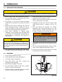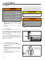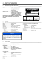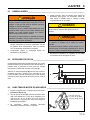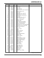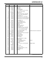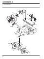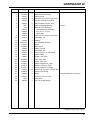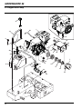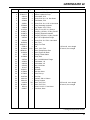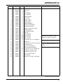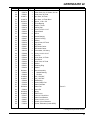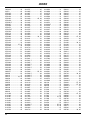
1
4268272-PT-Rev A
Technical Manual
Manual Técnico
GreensAire® 24
Model 58234
Modelo 58234
WARNING
If incorrectly used, this machine can cause severe injury. Those who use
and maintain this machine should be trained in its proper use, warned of its
dangers and should read the entire manual before attempting to set up,
operate, adjust or service the machine
AVISO
Utilizada incorrectamente, esta máquina pode provocar ferimentos graves.
Quem utilizar esta máquina e fizer a sua manutenção tem de ter formação
para a sua utilização correcta, tem de ser informado acerca dos perigos e
deve ler todo o manual antes de tentar configurar, trabalhar ou dar assistência
à máquina.
GB
PT
United
Kingdom
Portugal
When Performance Matters.™
FOREWORD
This manual contains safety, operating, adjustment,
maintenance, troubleshooting instructions, and parts list
for your new Jacobsen® aerator. This manual should be
stored with the aerator for reference during operation.
The serial plate is located on the right side of the frame
near the engine. Jacobsen recommends you record
these numbers below for easy reference.
Before you operate your aerator, you and each operator
you employ should read the manual carefully in its
entirety. By following the safety, operating, and
maintenance instructions, you will prolong the life of your
aerator and maintain its maximum efficiency.
If additional information is
Jacobsen Dealer.
®
A Textron Company
CHARLOTTE, NC
MADE IN U.S.A.
YEAR OF
PRODUCTION:
needed, contact your
Suggested Stocking Guide
To keep your aerator fully operational and productive, Jacobsen suggests you maintain a stock of the more commonly
used maintenance items. We have included part numbers for additional support materials and training aids.
To order any of the following material:
1. Write your full name and complete address on your
order form.
2. Explain where and how to make shipment:
❑ UPS
❑ Regular Mail
❑ Overnight
❑ 2nd Day
3. Order by the quantity desired, the part number, and
the description of the part.
4. Send or bring the order to your authorized Jacobsen
Dealer.
Service Parts
Qty. Part No.
Description
548481
876431
4113436
4113435
4113437
#50 Chain Connector Link
#40 Chain Connector Link
Belt, Mechanism
Belt, Transport
Belt, 2 Rib Mechanism
Qty. Part No.
Description
Service Support Material
Qty. Part No.
Description
Qty.
Description
4186981 Technical Manual
Proposition 65 Warning
© Copyright 2009, Jacobsen, A Textron Company.
All rights reserved, including the right to reproduce this material
or portions thereof in any form.
Litho in U.S.A. 3-2009
GB-2
This product contains or emits
chemicals known to State of California
to cause cancer and birth defects or
other reproductive harm.
Table of Contents
1
1.1
1.2
2
2.1
2.2
2.3
2.4
2.5
2.6
3
3.1
3.2
4
4.1
5
5.1
5.2
5.3
5.4
5.5
5.6
5.7
5.8
5.9
6
6.1
6.2
6.3
6.4
6.5
6.6
6.7
6.8
Safety
Operating Safety ................................................ 4
Important Safety Notes ....................................... 5
Specifications
Product Identification.......................................... 6
Engine ................................................................ 6
Aerator ................................................................ 6
Aerator ................................................................ 7
Weights and Dimensions .................................... 7
Accessories & Support Literature ....................... 7
Decals and Icons
Decals ................................................................ 8
Icons ................................................................... 8
Controls
Control Descriptions ........................................... 9
Operation
Daily Inspection ................................................ 11
Operator Presence Control (OPC) ................... 11
Operating Procedures ...................................... 12
Starting ............................................................. 12
Stopping / Parking ............................................ 13
To Drive / Transport ......................................... 13
Hillside Operation ............................................. 13
Aerating ............................................................ 14
Trailering .......................................................... 14
Adjustments
General............................................................. 15
Turf Guard ........................................................ 15
Aerator Drive Idler Cable .................................. 15
Traction Drive Idler Cable ................................. 16
Aerator Timing .................................................. 16
Shift Control Cable ........................................... 17
Lift Cable .......................................................... 17
Torque Specification ......................................... 18
7
7.1
7.2
7.3
7.4
7.5
7.6
7.7
7.8
7.9
7.10
7.11
7.12
7.13
8
8.1
9
9.1
9.2
10
11
12
12.1
12.2
12.1
Maintenance
General ............................................................ 19
Engine .............................................................. 19
Engine Oil ......................................................... 20
Engine Air Filter ................................................ 20
Fuel .................................................................. 20
Hydraulic Hoses ............................................... 21
Hydraulic Oil ..................................................... 21
Muffler and Exhaust ......................................... 22
Tires ................................................................. 22
Wheel Mounting Procedure .............................. 22
Care and Cleaning ........................................... 22
Pushrod Installation .......................................... 23
Storage ............................................................. 23
Troubleshooting
General ............................................................ 24
Maintenance & Lubrication Charts
General ............................................................ 25
Maintenance Charts ......................................... 25
tine selection guide
Parts Catalog
How To Use The Parts Catalog ....................... 27
To Order Parts ................................................. 27
Table Of Contents ............................................ 27
GB-3
1
1
1.1
SAFETY
SAFETY
OPERATING SAFETY ______________________________________________________
! WARNING
EQUIPMENT OPERATED IMPROPERLY OR BY UNTRAINED PERSONNEL CAN BE DANGEROUS.
Familiarize yourself with the location and proper use of all controls. Inexperienced operators should receive
instruction from someone familiar with the aerator before being allowed unsupervised operation of the aerator.
1. Safety is dependent upon the awareness, concern,
and prudence of those who operate or service the
aerator. Never allow minors to operate any
equipment.
2. It is your responsibility to read this manual and all
publications associated with this aerator (Engine
Manual, accessories, and attachments). If the
operator can not read English it is the owner’s
responsibility to explain the material contained in
this manual to them.
3. Learn the proper use of the aerator, the location and
purpose of all the controls before you operate the
equipment. Working with unfamiliar equipment can
lead to accidents.
4. Never allow anyone to operate or service the
aerator or its attachments without proper training
and instructions or while under the influence of
alcohol or drugs.
5. Wear all the necessary protective clothing and
personal safety devices to protect your head, eyes,
ears, hands, and feet. Operate the machine only in
daylight or in good artificial light.
9. Carbon monoxide in the exhaust fumes can be fatal
when inhaled. Never operate the engine without
proper ventilation.
10. Fuel is highly flammable. Handle with care.
11. Keep the engine clean. Allow the engine to cool
before storing and always remove the spark plug
wire.
12. Disengage all drives and engage parking brake
before starting the engine (motor).
13. Never use your hands to search for oil leaks.
Hydraulic fluid under pressure can penetrate the
skin and cause serious injury.
14. Operate the machine up and down the face of the
slopes (vertically) not across the face (horizontally).
15. To prevent tipping or loss of control, do not start or
stop suddenly on slopes. Reduce speed when
making sharp turns. Use caution when changing
direction on slopes.
6. Inspect the area where the equipment will be used.
Pick up all the debris you can find before operating.
Beware of overhead obstructions (low tree limbs,
electrical wires, etc.) and also underground
obstacles (sprinklers, pipes, tree roots, etc.) Enter a
new area cautiously. Do not enter narrow openings
that may force operator too close to aerator. Stay
alert for hidden hazards.
7. Never direct discharge of material toward
bystanders nor allow anyone near the aerator while
in operation. The owner/operator can prevent, and
is responsible for, injuries inflicted to themselves, to
bystanders, and damage to property.
8. Never operate equipment that is not in perfect
working order or is without decals, guards, shields,
discharge deflectors, or other protective devices
securely fastened in place.
This machine is to be operated and maintained as specified in this manual and is intended for the professional
maintenance of specialized turf grasses. It is not intended for use on rough terrain or long grasses.
4
SAFETY
1.2
1
IMPORTANT SAFETY NOTES ________________________________________________
This safety alert symbol is used to alert you to potential hazards.
DANGER - Indicates an imminently hazardous situation which, if not avoided, WILL result in death or serious injury.
WARNING - Indicates a potentially hazardous situation which, if not avoided, COULD result in death or serious
injury.
CAUTION - Indicates a potentially hazardous situation which, if not avoided, MAY result in minor or moderate injury
and property damage. It may also be used to alert against unsafe practices.
NOTICE - Indicates a potentially hazardous situation which, if not avoided, MAY result in property damage. It may
also be used to alert against unsafe practices.
For pictoral clarity, some illustrations in this manual may show shields, guards or plates open or removed. Under no
circumstances should this equipment be operated without these devices securely fastened in place.
! WARNING
The Operator Presence Control (OPC) on this machine will shut off the
aerator and traction drive if the operator releases the OPC handle.
To protect the operator and others from injury, never operate the aerator with
the OPC system disconnected or malfunctioning.
! WARNING
1. Before leaving the operator’s position for any reason:
a.
b.
c.
d.
Release OPC handle.
Lower aerator head to the ground.
Stop engine.
Disconnect spark plug wire.
2. Keep hands, feet, and clothing away from moving parts. Wait for all
movement to stop before you clean, adjust, or service the machine.
3. Keep the area of operation clear of all bystanders and pets.
4. Never carry passengers.
5. Never operate mowing equipment without the discharge deflector
securely fastened in place.
By following all instructions in this manual you will prolong the life of your machine and maintain its maximum efficiency.
Adjustments and maintenance should always be performed by a qualified technician.
If additional information or service is needed, contact your Authorized Jacobsen Dealer who is kept informed of the
latest methods to service this equipment and can provide prompt and efficient service.
5
2
SPECIFICATIONS
2
2.1
SPECIFICATIONS
PRODUCT IDENTIFICATION_________________________________________________
58234 .............................. GreensAire 24 Aerator with OPC,
10 hp gasoline engine.
Serial Number ................ An identification plate, like the one
shown, listing the serial number, is
attached to the right side frame,
near the engine.
Always provide the serial number of the unit when ordering
replacement parts or requesting service information.
2.2
358
6.9
XXXX
58234001651
Product
EEC Sound
Power
Operator
Ear
Vibration M/S2
58234
105 dBa
88 dBa
4.335
Arms
ENGINE__________________________________________________________________
Make ............................... Briggs & Stratton
Model .............................. Vanguard
Horsepower .................... 10 hp (7.46 kW) @3600 RPM
Displacement .................. 18.61 cu. in. (305 cc)
Bore x Stroke .................. 3.12 x 2.44 in. (79 x 62 mm)
Fuel:
Type .......................... Unleaded Gasoline
Governor......................... Flyweight Mechanical
Lubrication:
Capacity.................... 28 oz. (0.8 liters)
Type.......................... SAE 30W
API Classification ..... SG, SH, SJ
Air Filter .......................... Replaceable Dual Element
Cooling System .............. Air Cooled
Rating ....................... Min. 85 Octane
Capacity .................... 2.5 U.S. gal. (9.5 liters)
NOTICE
Do not use premium gasoline or an oil-gasoline
mixture. When using blended fuel, do not use a blend
with more than 10% ethanol. Under no circumstances
should you use a blend with methanol.
2.3
AERATOR________________________________________________________________
Spacing ........................... 2 in. (51 mm) on center
Depth of Penetration ....... 3 in. (76 mm) maximum
Standard Tine
Type .......................... Duratine XLT top eject
Material ..................... Hardened steel with carbide tip
Quantity .................... Two sets 1/2 in. (13 mm) diameter
Tine Options
Solid .......................... 1/4 in. (6 mm), 3/8 in. (9 mm), 5/8
(16 mm)
Top Eject Coring ....... 1/4 in. (6 mm), 3/8 in. (9 mm),
1/2 in. (13 mm), 5/8 in. (16 mm)
Side Eject Coring ...... 1/4 in. (6 mm)
Quad Tines ............... 1/4 in. (6 mm) Solid, 1/4 in. (6 mm)
coring, 1/2 in. (13 mm) coring
Swath Width.................... 24 in. (609 mm)
6
SPECIFICATIONS
2.4
2
AERATOR ________________________________________________________________
Tires
Front.......................... 11 x 4.00 - 5 2 Ply
Rear .......................... 16 x 6.50 - 8 4 Ply
Pressure:................... 14 psi (97 kPa)
Speed:
H (Transport) ........... 0 - 4.0 mph (6.4 kph)
L (Aerate).................. 0 - 0.9 mph (1.4 kph)
R (Reverse) .............. 0 - 1.8 mph (2.9 kph)
Hydraulic System:
Capacity.................... 2 U.S. gal. (7.57 liters)
Fluid Type ................. GreensCare 68™
Aerator Head Lift....... Hydraulic Double Acting Cylinders
2.5
WEIGHTS AND DIMENSIONS ________________________________________________
Dimensions:
Inches
(mm)
Length ............................................................. 72 (1676)
Width ............................................................ 49.5 (1257)
Height.............................................................. 48 (1219)
2.6
Weights:
Lbs.
Working Weight Less Fuel ............................ 850
(kg)
(386)
ACCESSORIES & SUPPORT LITERATURE _____________________________________
Contact your area Jacobsen Dealer for a complete listing of accessories and attachments.
! CAUTION
Use of other than Jacobsen authorized parts and accessories may cause personal injury or damage to the
equipment.
Accessories
Orange Touch-up Paint (12 oz. spray) .................... 4184140
1/4 in. Solid Quad Tine Accessory ...........................4116986
1/4 in. Coring Quad Tine Accessory ........................4116987
1/2 in. Coring Quad Tine Accessory ........................... 58231
Pushrod Installation Tool ........................................... 517693
Windrow Attachment Accessory ............................... 544918
Tines
1/4 in. (6 mm) Coring, 5/8 in. O.D. ............................ 517486
1/4 in. (6 mm) Solid, 1/2 in. O.D................................ 523863
3/8 in. (9 mm) Coring, 5/8 in. O.D. ............................ 517487
1/2 in. (13 mm) Coring, 5/8 in. O.D. .......................... 517488
5/8 in. (16 mm) Coring, 3/4 in. O.D. .......................... 517489
VenTine, 5/8 in. O.D................................................ 2702060
Tine Holders
Tine Holder, 1/2 in. O.D. Tines...................................547849
l Tine Holder, 5/8 in. O.D. Tines.................................547860
Tine Holder, 3/4 in. O.D. Tines...................................547861
Support Literature
Technical Manual .....................................................4268272
Operator Training DVD ............................................4191623
l
GA-24 is supplied with twenty four 1/2 in. (13 mm)
coring tines (4180567) and six 5/8 in. O.D. tine holders
(547860).
DuraTines
1/4 in. (6 mm) Coring, 1/2 in. O.D. (XLT) ................ 4180561
1/4 in. (6 mm) Solid, 1/2 in. O.D. (XL)..................... 4180562
1/4 in. (6 mm) Solid, 5/8 in. O.D. (XL)..................... 4180563
3/8 in. (9 mm) Solid, 5/8 in. O.D. (XL)..................... 4180564
1/2 in. (13 mm) Coring, 5/8 in. O.D. (XL) ................ 4180566
l 1/2 in. (13 mm) Coring, 5/8 in. O.D. (XLT) ............ 4180567
5/8 in. (16 mm) Coring, 3/4 in. O.D. (XL) ................ 4180571
5/8 in. (16 mm) Coring, 3/4 in. O.D. (XLT) .............. 4180572
5/8 in. (16 mm) Solid, 3/4 in. O.D. (XL)................... 4180573
7
2
SPECIFICATIONS
2.7
DECLARATION OF CONFORMITY ____________________________________________
DECLARATION OF CONFORMITY ▪ ДЕКЛАРАЦИЯ ЗА СЪОТВЕТСТВИЕ ▪ PROHLÁŠENÍ O SHODĚ ▪
OVERENSSTEMMELSESERKLÆRING ▪ CONFORMITEITSVERKLARING ▪ VASTAVUSDEKLARATSIOON ▪
VAATIMUSTENMUKAISUUSVAKUUTUS ▪ DECLARATION DE CONFORMITE ▪ KONFORMITÄTSERKLÄRUNG ▪
∆ΗΛΩΣΗ ΣΥΜΜΟΡΦΩΣΗΣ ▪ MEGFELELŐSÉGI NYILATKOZAT ▪ DICHIARAZIONE DI CONFORMITÀ ▪ ATBILSTĪBAS
DEKLARĀCIJA ▪ ATITIKTIES DEKLARACIJA ▪ DIKJARAZZJONI TAL-KONFORMITÀ ▪ DEKLARACJA ZGODNOŚCI ▪
DECLARAÇÃO DE CONFORMIDADE ▪ DECLARAŢIE DE CONFORMITATE ▪ VYHLÁSENIE O ZHODE ▪ IZJAVA O
SKLADNOSTI ▪ DECLARACIÓN DE CONFORMIDAD ▪ DEKLARATION OM ÖVERENSSTÄMMELSE
Business name and full address of the manufacturer ▪ Търговско име и пълен адрес на производителя ▪ Obchodní jméno a plná adresa výrobce ▪
Producentens firmanavn og fulde adresse ▪ Bedrijfsnaam en volledig adres van de fabrikant ▪ Tootja ärinimi ja täielik aadress ▪
Valmistajan toiminimi ja täydellinen osoite ▪ Nom commercial et adresse complète du fabricant ▪ Firmenname und vollständige Adresse des Herstellers ▪
Επωνυμία και ταχυδρομική διεύθυνση κατασκευαστή ▪ A gyártó üzleti neve és teljes címe ▪ Ragione sociale e indirizzo completo del fabbricante ▪
Uzņēmuma nosaukums un pilna ražotāja adrese ▪ Verslo pavadinimas ir pilnas gamintojo adresas ▪ Isem kummerċjali u indirizz sħiħ tal-fabbrikant ▪
Nazwa firmy i pełny adres producenta ▪ Nome da empresa e endereço completo do fabricante ▪ Denumirea comercială şi adresa completă a
producătorului ▪ Obchodný názov a úplná adresa výrobcu ▪ Naziv podjetja in polni naslov proizvajalca ▪ Nombre de la empresa y dirección completa del
fabricante ▪ Tillverkarens företagsnamn och kompletta adress
Jacobsen, A Textron Company
11524 Wilmar Blvd.
Charlotte, NC 28273, USA
Product Code ▪ Код на продукта ▪ Kód výrobku ▪ Produktkode ▪ Productcode ▪ Toote kood ▪ Tuotekoodi ▪ Code produit ▪ Produktcode ▪ Κωδικός προϊόντος
▪ Termékkód ▪ Codice prodotto ▪ Produkta kods ▪ Produkto kodas ▪ Kodiċi tal-Prodott ▪ Kod produktu ▪ Código do Produto ▪ Cod produs ▪ Kód výrobku ▪
58234
Oznaka proizvoda ▪ Código de producto ▪ Produktkod
Machine Name ▪ Наименование на машината ▪ Název stroje ▪ Maskinnavn ▪ Machinenaam ▪ Masina nimi ▪ Laitteen nimi ▪ Nom de la machine ▪
Maschinenbezeichnung ▪ Ονομασία μηχανήματος ▪ Gépnév ▪ Denominazione della macchina ▪ Iekārtas nosaukums ▪ Mašinos pavadinimas ▪ Isem talMagna ▪ Nazwa urządzenia ▪ Nome da Máquina ▪ Numele echipamentului ▪ Názov stroja ▪ Naziv stroja ▪ Nombre de la máquina ▪ Maskinens namn
GA-24
Designation ▪ Предназначение ▪ Označení ▪ Betegnelse ▪ Benaming ▪ Nimetus ▪ Tyyppimerkintä ▪ Pažymėjimas ▪ Bezeichnung ▪ Χαρακτηρισμός ▪
Megnevezés ▪ Funzione ▪ Apzīmējums ▪ Lithuanian ▪ Denominazzjoni ▪ Oznaczenie ▪ Designação ▪ Specificaţie ▪ Označenie ▪ Namen stroja ▪ Descripción Scarifier, Article 13, Item 49
▪ Beteckning
Serial Number ▪ Сериен номер ▪ Sériové číslo ▪ Serienummer ▪ Serienummer ▪ Seerianumber ▪ Valmistusnumero ▪ Numéro de série ▪ Seriennummer ▪
Σειριακός αριθμός ▪ Sorozatszám ▪ Numero di serie ▪ Sērijas numurs ▪ Serijos numeris ▪ Numru Serjali ▪ Numer seryjny ▪ Número de Série ▪ Număr de
serie ▪ Sériové číslo ▪ Serijska številka ▪ Número de serie ▪ Serienummer
5823401651-5823404500
Engine ▪ Двигател ▪ Motor ▪ Motor ▪ Motor ▪ Mootor ▪ Moottori ▪ Moteur ▪ Motor ▪ Μηχανή ▪ Modulnév ▪ Motore ▪ Dzinējs ▪ Variklis ▪ Saħħa Netta Installata ▪
Briggs and Stratton Vanguard
Silnik ▪ Motor ▪ Motor ▪ Motor ▪ Motor ▪ Motor ▪ Motor
Net Installed Power ▪ Нетна инсталирана мощност ▪ Čistý instalovaný výkon ▪ Installeret nettoeffekt ▪ Netto geïnstalleerd vermogen ▪ Installeeritud
netovõimsus ▪ Asennettu nettoteho ▪ Puissance nominale nette ▪ Installierte Nettoleistung ▪ Καθαρή εγκατεστημένη ισχύς ▪ Nettó beépített teljesítmény ▪
Potenza netta installata ▪ Paredzētā tīkla jauda ▪ Grynoji galia ▪ Wisa’ tal-Qtugħ ▪ Moc zainstalowana netto ▪ Potência instalada ▪ Puterea instalată netă ▪
Čistý inštalovaný výkon ▪ Neto vgrajena moč ▪ Potencia instalada neta ▪ Nettoeffekt
6,71 kW @ 3600 RPM
Cutting Width ▪ Широчина на рязане ▪ Šířka řezu ▪ Skærebredde ▪ Maaibreedte ▪ Lõikelaius ▪ Leikkuuleveys ▪ Largeur de coupe ▪ Schnittbreite ▪
Μήκος μισινέζας ▪ Vágási szélesség ▪ Larghezza di taglio ▪ Griešanas platums ▪ Pjovimo plotis ▪ Tikkonforma mad-Direttivi ▪ Szerokość cięcia ▪
Largura de Corte ▪ Lăţimea de tăiere ▪ Šírka záberu ▪ Širina reza ▪ Anchura de corte ▪ Klippbredd
NA
Conforms to Directives ▪ В съответствие с директивите ▪ Splňuje podmínky směrnic ▪ Er i overensstemmelse med direktiver ▪ Voldoet aan de richtlijnen ▪
Vastab direktiividele ▪ Direktiivien mukainen ▪ Conforme aux directives ▪ Entspricht Richtlinien ▪ Ακολουθήστε πιστά τις Οδηγίες ▪ Megfelel az irányelveknek
▪ Conforme alle Direttive ▪ Atbilst direktīvām ▪ Atitinka direktyvų reikalavimus ▪ Valutazzjoni tal-Konformità ▪ Dyrektywy związane ▪ Cumpre as Directivas ▪
Respectă Directivele ▪ Je v súlade so smernicami ▪ Skladnost z direktivami ▪ Cumple con las Directivas ▪ Uppfyller direktiv
2004/108/EC
2006/42/EC
2000/14/EC, 2005/88/EC
2006/66/EC
Conformity Assessment ▪ Оценка за съответствие ▪ Hodnocení plnění podmínek ▪ Overensstemmelsesvurdering ▪ Conformiteitsbeoordeling ▪
Vastavushindamine ▪ Vaatimustenmukaisuuden arviointi ▪ Evaluation de conformité ▪ Konformitätsbeurteilung ▪ ∆ιαπίστωση Συμμόρφωσης ▪
Megfelelőség-értékelés ▪ Valutazione della conformità ▪ Atbilstības novērtējums ▪ Atitikties įvertinimas ▪ Livell tal-Qawwa tal-Ħoss Imkejjel ▪ Ocena
zgodności ▪ Avaliação de Conformidade ▪ Evaluarea conformităţii ▪ Vyhodnotenie zhodnosti ▪ Ocena skladnosti ▪ Evaluación de conformidad ▪
Bedömning av överensstämmelse
2006/42/EC Annex VIII
Measured Sound Power Level ▪ Измерено ниво на звукова мощност ▪ Naměřený akustický výkon ▪ Målte lydstyrkeniveau ▪ Gemeten geluidsniveau ▪
Mõõdetud helivõimsuse tase ▪ Mitattu äänitehotaso ▪ Niveau de puissance sonore mesuré ▪ Gemessener Schalldruckpegel ▪
Σταθμισμένο επίπεδο ηχητικής ισχύος ▪ Mért hangteljesítményszint ▪ Livello di potenza sonora misurato ▪ Izmērītais skaņas jaudas līmenis ▪
Išmatuotas garso stiprumo lygis ▪ Livell tal-Qawwa tal-Ħoss Iggarantit ▪ Moc akustyczna mierzona ▪ Nível sonoro medido ▪ Nivelul măsurat al puterii
acustice ▪ Nameraná hladina akustického výkonu ▪ Izmerjena raven zvočne moči ▪ Nivel de potencia sonora medido ▪ Uppmätt ljudeffektsnivå
105 dB(A) LWA
Guaranteed Sound Power Level ▪ Гарантирано ниво на звукова мощност ▪ Garantovaný akustický výkon ▪ Garanteret lydstyrkeniveau ▪
Gegarandeerd geluidsniveau ▪ Garanteeritud helivõimsuse tase ▪ Taattu äänitehotaso ▪ Niveau de puissance sonore garanti ▪ Garantierter
Schalldruckpegel ▪ Εγγυημένο επίπεδο ηχητικής ισχύος ▪ Szavatolt hangteljesítményszint ▪ Livello di potenza sonora garantito ▪ Garantētais skaņas
jaudas līmenis ▪ Garantuotas garso stiprumo lygis ▪ Livell tal-Qawwa tal-Ħoss Iggarantit ▪ Moc akustyczna gwarantowana ▪ Nível sonoro farantido ▪
Nivelul garantat al puterii acustice ▪ Garantovaná hladina akustického výkonu ▪ Zajamčena raven zvočne moči ▪ Nivel de potencia sonora garantizado ▪
Garanterad ljudeffektsnivå
105 dB(A) LWA
Conformity Assessment Procedure (Noise) ▪ Оценка за съответствие на процедурата (Шум) ▪ Postup hodnocení plnění podmínek (hluk) ▪
Procedure for overensstemmelsesvurdering (Støj) ▪ Procedure van de conformiteitsbeoordeling (geluid) ▪ Vastavushindamismenetlus (müra) ▪
Vaatimustenmukaisuuden arviointimenettely (Melu) ▪ Procédure d’évaluation de conformité (bruit) ▪ Konformitätsbeurteilungsverfahren (Geräusch) ▪
∆ιαδικασία Αξιολόγησης Συμμόρφωσης (Θόρυβος) ▪ Megfelelőség-értékelési eljárás (Zaj) ▪ Procedura di valutazione della conformità (rumore) ▪
Atbilstības novērtējuma procedūra (troksnis) ▪ Atitikties įvertinimo procedūra (garsas) ▪ Proċedura tal-Valutazzjoni tal-Konformità (Ħoss) ▪
Procedura oceny zgodności (poziom hałasu) ▪ Processo de avaliação de conformidade (nível sonoro) Procedura de evaluare a conformităţii (zgomot) ▪
Postup vyhodnocovania zhodnosti (hluk) ▪ Postopek za ugotavljanje skladnosti (hrup) ▪ Procedimiento de evaluación de conformidad (ruido) ▪
Procedur för bedömning av överensstämmelse (buller)
2000/14/EC Annex V
UK Notified Body for 2000/14/EC ▪ Нотифициран орган в Обединеното кралство за 2000/14/ЕО ▪ Úřad certifikovaný podle směrnice č. 2000/14/EC ▪
Det britiske bemyndigede organ for 2001/14/EF ▪ Engels adviesorgaan voor 2000/14/EG ▪ Ühendkuningriigi teavitatud asutus direktiivi 2000/14/EÜ
mõistes ▪ Direktiivin 2000/14/EY mukainen ilmoitettu tarkastuslaitos Isossa-Britanniassa ▪ Organisme notifié concernant la directive 2000/14/CE ▪
Britische benannte Stelle für 2000/14/EG ▪ Κοινοποιημένος Οργανισμός Ηνωμένου Βασιλείου για 2000/14/ΕΚ ▪
2000/14/EK – egyesült királyságbeli bejelentett szervezet ▪ Organismo Notificato in GB per 2000/14/CE ▪ 2000/14/EK AK reģistrētā organizācija ▪
JK notifikuotosios įstaigos 2000/14/EC ▪ Korp Notifikat tar-Renju Unit għal 2000/14/KE ▪ Dopuszczona jednostka badawcza w Wielkiej Brytanii wg 2000/
14/WE ▪ Entidade notificada no Reino Unido para 2000/14/CE ▪ Organism notificat în Marea Britanie pentru 2000/14/CE ▪
Notifikovaný orgán Spojeného kráľovstva pre smernicu 2000/14/ES ▪ Britanski priglašeni organ za 2000/14/ES ▪
Cuerpo notificado en el Reino Unido para 2000/14/CE ▪ Anmält organ för 2000/14/EG i Storbritannien
Number: 1088
Sound Research Laboratories Limited
Holbrook House, Little Waldingfield
Sudbury, Suffolk CO10 0TH
Operator Ear Noise Level ▪ Оператор на нивото на доловим от ухото шум ▪ Hladina hluku v oblasti uší operátora ▪ Støjniveau i førers ørehøjde ▪
Geluidsniveau oor bestuurder ▪ Müratase operaatori kõrvas ▪ Melutaso käyttäjän korvan kohdalla ▪ Niveau de bruit à hauteur des oreilles de l’opérateur ▪
Schallpegel am Bedienerohr ▪ Επίπεδο θορύβου σε λειτουργία ▪ A kezelő fülénél mért zajszint ▪ Livello di potenza sonora all’orecchio dell’operatore ▪
Trokšņa līmenis pie operatora auss ▪ Dirbančiojo su mašina patiriamo triukšmo lygis ▪ Livell tal-Ħoss fil-Widna tal-Operatur ▪
Dopuszczalny poziom hałasu dla operatora ▪ Nível sonoro nos ouvidos do operador ▪ Nivelul zgomotului la urechea operatorului ▪
Hladina hluku pôsobiaca na sluch operátora ▪ Raven hrupa pri ušesu upravljavca ▪ Nivel sonoro en el oído del operador ▪ Ljudnivå vid förarens öra
88 dB(a) Leq (2006/42/EC)
8
SPECIFICATIONS
2
Harmonised standards used ▪ Използвани хармонизирани стандарти ▪ Použité harmonizované normy ▪ Brugte harmoniserede standarder ▪
Gebruikte geharmoniseerde standaards ▪ Kasutatud ühtlustatud standardid ▪ Käytetyt yhdenmukaistetut standardit ▪ Normes harmonisées utilisées ▪
BS EN ISO 20643
Angewandte harmonisierte Normen ▪ Εναρμονισμένα πρότυπα που χρησιμοποιήθηκαν ▪ Harmonizált szabványok ▪ Standard armonizzati applicati ▪
BS EN ISO 5349-1
Izmantotie saskaņotie standarti ▪ Panaudoti suderinti standartai ▪ Standards armonizzati użati ▪ Normy spójne powiązane ▪ Normas harmonizadas usadas
BS EN ISO 5349-2
▪ Standardele armonizate utilizate ▪ Použité harmonizované normy ▪ Uporabljeni usklajeni standardi ▪ Estándares armonizados utilizados ▪
Harmoniserade standarder som används
Technical standards and specifications used ▪ Използвани технически стандарти и спецификации ▪ Použité technické normy a specifikace ▪
Brugte tekniske standarder og specifikationer ▪ Gebruikte technische standaards en specificaties ▪ Kasutatud tehnilised standardid ja spetsifikatsioonid ▪
Käytetyt tekniset standardit ja eritelmät ▪ Spécifications et normes techniques utilisées ▪ Angewandte technische Normen und Spezifikationen ▪
Τεχνικά πρότυπα και προδιαγραφές που χρησιμοποιήθηκαν ▪ Műszaki szabványok és specifikációk ▪ Standard tecnici e specifiche applicati ▪
Izmantotie tehniskie standarti un specifikācijas ▪ Panaudoti techniniai standartai ir techninė informacija ▪ Standards u speċifikazzjonijiet tekniċi użati ▪
Normy i specyfikacje techniczne powiązane ▪ Normas técnicas e especificações usadas ▪ Standardele tehnice şi specificaţiile utilizate ▪
Použité technické normy a špecifikácie ▪ Uporabljeni tehnični standardi in specifikacije ▪ Estándares y especificaciones técnicas utilizadas ▪
Tekniska standarder och specifikationer som används
ISO 2631-1
The place and date of the declaration ▪ Място и дата на декларацията ▪ Místo a datum prohlášení ▪ Sted og dato for erklæringen ▪
Plaats en datum van de verklaring ▪ Deklaratsiooni väljastamise koht ja kuupäev ▪ Vakuutuksen paikka ja päivämäärä ▪ Lieu et date de la déclaration ▪
Ort und Datum der Erklärung ▪ Τόπος και ημερομηνία δήλωσης ▪ A nyilatkozat kelte (hely és idő) ▪ Luogo e data della dichiarazione ▪
Deklarācijas vieta un datums ▪ Deklaracijos vieta ir data ▪ Il-post u d-data tad-dikjarazzjoni ▪ Miejsce i data wystawienia deklaracji ▪ Local e data da
declaração ▪ Locul şi data declaraţiei ▪ Miesto a dátum vyhlásenia ▪ Kraj in datum izjave ▪ Lugar y fecha de la declaración ▪ Plats och datum för
deklarationen
Jacobsen, A Textron Company
11524 Wilmar Blvd.
Charlotte, NC 28273, USA
May 1, 2011
Signature of the person empowered to draw up the declaration on behalf of the manufacturer, holds the technical documentation and is authorised to
compile the technical file, and who is established in the Community.
Подпис на човека, упълномощен да състави декларацията от името на производителя, който поддържащ техническата документация и е
оторизиран да изготви техническия файл и е регистриран в общността.
Podpis osoby oprávněné sestavit prohlášení jménem výrobce, držet technickou dokumentaci a osoby oprávněné sestavit technické soubory a založené v
rámci Evropského společenství.
Underskrift af personen, der har fuldmagt til at udarbejde erklæringen på vegne af producenten, der er indehaver af dokumentationen og er bemyndiget til
at udarbejde den tekniske journal, og som er baseret i nærområdet.
Handtekening van de persoon die bevoegd is de verklaring namens de fabrikant te tekenen, de technische documentatie bewaart en bevoegd is om het
technische bestand samen te stellen, en die is gevestigd in het Woongebied.
Ühenduse registrisse kantud isiku allkiri, kes on volitatud tootja nimel deklaratsiooni koostama, kes omab tehnilist dokumentatsiooni ja kellel on õigus
koostada tehniline toimik.
Sen henkilön allekirjoitus, jolla on valmistajan valtuutus vakuutuksen laadintaan, jolla on hallussaan tekniset asiakirjat, joka on valtuutettu laatimaan
tekniset asiakirjat ja joka on sijoittautunut yhteisöön.
Signature de la personne habilitée à rédiger la déclaration au nom du fabricant, à détenir la documentation technique, à compiler les fichiers techniques et
qui est implantée dans la Communauté.
Unterschrift der Person, die berechtigt ist, die Erklärung im Namen des Herstellers abzugeben, die die technischen Unterlagen aufbewahrt und berechtigt
ist, die technischen Unterlagen zusammenzustellen, und die in der Gemeinschaft niedergelassen ist.
Υπογραφή ατόμου εξουσιοδοτημένου για την σύνταξη της δήλωσης εκ μέρους του κατασκευαστή, ο οποίος κατέχει την τεχνική έκθεση και έχει την
εξουσιοδότηση να ταξινομήσει τον τεχνικό φάκελο και ο οποίος είναι διορισμένος στην Κοινότητα.
A gyártó nevében meghatalmazott személy, akinek jogában áll módosítania a nyilatkozatot, a műszaki dokumentációt őrzi, engedéllyel rendelkezik a
műszaki fájl összeállításához, és aki a közösségben letelepedett személy.
Firma della persona autorizzata a redigere la dichiarazione a nome del fabbricante, in possesso Della documentazione tecnica ed autorizzata a costituire
il fascicolo tecnico, che deve essere stabilita nella Comunità.
Tās personas paraksts, kura ir pilnvarota deklarācijas sastādīšanai ražotāja vārdā, kurai ir tehniskā dokumentācija, kura ir pilnvarota sagatavot tehnisko
reģistru un kura ir apstiprināta Kopienā.
Asmuo, kuris yra gana žinomas, kuriam gamintojas suteikė įgaliojimus sudaryti šią deklaraciją, ir kuris ją pasirašė, turi visą techninę informaciją ir yra
įgaliotas sudaryti techninės informacijos dokumentą.
Il-firma tal-persuna awtorizzata li tfassal id-dikjarazzjoni f’isem il-fabbrikant, għandha d-dokumentazzjoni teknika u hija awtorizzata li tikkompila l-fajl
tekniku u li hija stabbilita fil-Komunità.
Podpis osoby upoważnionej do sporządzenia deklaracji w imieniu producenta, przechowującej dokumentację techniczną, upoważnioną do stworzenia
dokumentacji technicznej oraz wyznaczonej ds. wspólnotowych.
Assinatura da pessoa com poderes para emitir a declaração em nome do fabricante, que possui a documentação técnica, que está autorizada a compilar
o processo técnico e que está estabelecida na Comunidade.
Semnătura persoanei împuternicite să elaboreze declaraţia în numele producătorului, care deţine documentaţia tehnică, este autorizată să compileze
dosarul tehnic şi este stabilită în Comunitate.
Podpis osoby poverenej vystavením vyhlásenia v mene výrobcu, ktorá má technickú dokumentáciu a je oprávnená spracovať technické podklady a ktorá
je umiestnená v Spoločenstve.
Podpis osebe, pooblaščene za izdelavo izjave v imenu proizvajalca, ki ima tehnično dokumentacijo in lahko sestavlja spis tehnične dokumentacije, ter ima
sedež v Skupnosti.
Firma de la persona responsable de la declaración en nombre del fabricante, que posee la documentación técnica y está autorizada para recopilar el
archivo técnico y que está establecido en la Comunidad.
Undertecknas av den som bemyndigad att upprätta deklarationen å tillverkarens vägnar, innehar den tekniska dokumentationen och är bemyndigad att
sammanställa den tekniska informationen och som är etablerad i gemenskapen.
Certificate Number ▪ Номер на сертификат ▪ Číslo osvědčení ▪ Certifikatnummer ▪ Certificaatnummer ▪ Sertifikaadi number ▪ Hyväksyntänumero ▪
Numéro de certificat ▪ Bescheinigungsnummer ▪ Αριθμός Πιστοποιητικού ▪ Hitelesítési szám ▪ Numero del certificato ▪ Sertifikāta numurs ▪
Sertifikato numeris ▪ Numru taċ-Ċertifikat ▪ Numer certyfikatu ▪ Número do Certificado ▪ Număr certificat ▪ Číslo osvedčenia ▪ Številka certifikata ▪
Número de certificado ▪ Certifikatsnummer
2006/42/EC Annex II 1.A.2
Tim Lansdell
Technical Director
Ransomes Jacobsen Limited
West Road, Ransomes Europark,
Ipswich, IP3 9TT, England
2006/42/EC Annex II 1.A.10
Vasant Godhalekar
VP of Engineering
Jacobsen, A Textron Company
11524 Wilmar Blvd,
Charlotte, NC 28273, USA
4268272 Rev A
GB
BG
CZ
DK
NL
EE
FI
FR
DE
GR
HU
English
български
čeština
dansk
Nederlands
eesti
suomi
français
Deutsch
Ελληνικά
magyar
IT
LV
LT
MT
PL
PT
RO
SK
SI
ES
SE
italiano
latviešu
valoda
lietuvių
kalba
Malki
polski
português
Română
slovenčina
Ελληνικά
Svenska
slovenščina
9
3
3
3.1
DECALS AND ICONS
DECALS AND ICONS
DECALS _________________________________________________________________
Familiarize yourself with the decals as they are critical to the safe operation of the aerator.
REPLACE DAMAGED DECALS IMMEDIATELY.
4164281
1
38
64
41
840891
3.2
ICONS ___________________________________________________________________
Read Manual
Fuel
OPC
Release
Engine Throttle
Fast
Choke
Slow
Tine Lever
Lift
Lower
! WARNING
Never attempt to operate the aerator unless you have read the Technical Manual and know
how to operate all controls correctly.
Familiarize yourself with the icons shown above and what they represent. Learn the
location and purpose of all the controls before operating the aerator.
10
Tine
Engage
CONTROLS
A
B
C
D
E
F
G
Clutch Control Lever
Throttle
Shift Control Lever
Tine Lever
4
OPC Handle
Engine Switch
Choke
A
F
R
N
H
L
G
C
E
D
B
4
4.1
CONTROLS
CONTROL DESCRIPTIONS _________________________________________________
A. Clutch Control Lever
Clutch control lever engages and disengages power
to tine operation clutch and latches OPC handle. Pull
lever until OPC handle (E) closes for transport. Pull
handle until it clicks and locks in place for tine
operation. Release the OPC handle to disengage.
B. Throttle
Controls the ground speed of the unit. Position lever
between Slow and Fast to set desired ground speed.
Fully raise lever to Stop position to shut off engine.
C. Shift Control Lever
Four position lever used to operate different functions
of machine.
R (Reverse): Engages
operation is locked out.
reverse
traction.
! WARNING
Damage to turf and/or aerator may occur if aerator
head is not fully raised before engaging OPC handle
with shift control lever (C) in R (Reverse) or H (High)
position.
N (Neutral): Disengages both traction and tine
operation.
H (High): Engages transport speed only. Tine
operation is locked out.
L (Low): Engages aerating traction speed. Tine
operation can be engaged.
Tine
11
4
CONTROLS
D. Tine Lever
Raises and lowers aerator head. Lift lever to Raise
position to raise head. Push lever to Lower position
to lower head.
! WARNING
A
To prevent injury from hot hydraulic oil, the Tine Lever
must be returned to the Neutral position after raising or
lowering the unit. If the lever sticks or is held in the
Raise or Lower position, the hydraulic fluid will
overheat, possibly causing a hydraulic line to rupture.
E. OPC Handle
Engages and disengages drive clutch. Returns clutch
control lever (A) to disengaged position when
released.
F.
N
H
L
C
E
B
Engine Switch
Controls engine operation. Move switch to ON
position for normal operation. Move switch to OFF
position to shut unit off or when adjusting, trailering,
or storing unit.
G. Choke
The choke lever opens and closes the choke valve in
the carburetor. The Closed position enriches the fuel
mixture for starting a cold engine. The Open position
provides the correct fuel mixture for operation after
starting and for restarting a warm engine.
12
R
D
F
G
OPERATION
5
5
OPERATION
5.1
DAILY INSPECTION ________________________________________________________
! CAUTION
The daily inspection should be performed only when
the engine is off and all fluids are cold. Lower aerator
head to the ground, stop engine, and disconnect
spark plug wire.
1. Perform a visual inspection of the entire aerator,
looking for signs of wear, loose hardware, and
missing or damaged components. Check for fuel or
oil leaks to ensure connections are tight and hoses
and tubes are in good condition.
2. Check the hydraulic oil level, fuel supply, crankcase
oil, and air cleaner. All fluids must be at the Full
level mark with engine cold.
3. Check tires for proper inflation.
5.2
OPERATOR PRESENCE CONTROL (OPC) _____________________________________
1. The OPC system is intended to protect the operator
and others from injury by stopping the aerator and
drive mechanism as soon as the operator releases
the OPC handle.
d.
e.
f.
! WARNING
Never operate equipment with the OPC system
disconnected or malfunctioning.
g.
Pull clutch control lever (A) slightly until OPC
handle (E) can be engaged. Engage tine operation.
h.
Release the OPC handle (E). The clutch control
lever (A) must return to disengaged position and
OPC handle must come up.
i.
Check each position of shift control lever (C). Tine
operation should only engage with lever in L (Low)
position.
2. Test OPC system.
a. Start the engine and place throttle (B) at Slow.
Fully raise aerator head.
b.
c.
Place shift control (C) in R (Reverse) position. In
this position, unit will move away from operator
when testing.
Pull clutch control lever (A) slightly until OPC
handle (E) can be engaged. Do not engage tine
operation.
With Engine Running
Shift
Control
Position
R
R
OPC Handle
Engaged
Disengaged
4
4
The drive mechanism will engage and the unit will
slowly move backward.
Release the OPC handle. The handle must come
up and the wheels must stop. Shut off engine.
Place shift control (C) in L (Low) position.
Without Engine Running
Can Clutch
Lever be Fully
Engaged
Gear Selector
R
No
N
No
H
No
L
Yes
3. Stop the engine immediately and have the system
repaired if any of the following occurs:
Wheels
Turn
No
Yes
a. The wheels begin to turn before the OPC handle
is engaged.
b.
The wheels continue to turn after the OPC handle is
released.
c.
Clutch control lever does not return to disengaged
position.
13
5
OPERATION
5.3
OPERATING PROCEDURES_________________________________________________
! CAUTION
To prevent injury, always wear safety glasses, leather work shoes or boots, a hard hat, and ear protection.
1. Before starting engine, always release OPC handle.
2. Do not operate aerator or attachments with loose,
damaged, or missing components.
3. First aerate in a test area to become thoroughly
familiar with the operation of the aerator and control
levers.
4. Study the work area to determine the best and
safest operating procedure. Consider the type of
terrain and condition of the surface. Each condition
will require certain adjustments or precautions.
5. Never direct discharge of material toward
bystanders nor allow anyone near the aerator while
in operation. The owner/operator is responsible for
injuries inflicted to bystanders and/or damage to
their property.
! CAUTION
struck by the aerator may cause serious injuries to
bystanders and/or damage the aerator.
7. Always raise aerator head and move control lever
out of L position when not aerating.
8. Disengage the tines and raise the aerator head
when crossing paths or roadways. Look out for
traffic.
9. Stop and inspect the equipment for damage
immediately after striking any obstruction or if the
machine begins to vibrate abnormally. Have the
equipment repaired before resuming operation.
! WARNING
Before you clean, adjust, or repair the aerator,
always disengage all drives, lower aerator head
to the ground, stop engine, and disconnect spark
plug wire to prevent injuries.
Before operating the aerator, pick up all debris such
as rocks, toys, and wire which may be thrown by the
machine. Enter a new area cautiously. Always operate
at speeds that allow you to have complete control of
the aerator.
10. Slow down and use extra care on hillsides. Read
Section 5.8. Use caution when operating near drop
offs.
6. Use discretion when operating near gravel areas
(roadways, parking areas, cart paths, etc.). Stones
12. Never use your hands to clean aerator. Tine edges
are sharp and can cause serious injuries.
5.4
11. Use care when approaching blind corners, shrubs,
trees, or other objects that may obscure vision.
STARTING _______________________________________________________________
1. Check engine crankcase oil levels.
2. Fill fuel tank with fresh, clean unleaded fuel.
3. Turn engine switch to ON position.
A
4. Place Shift Control Lever (C) in Neutral and
disengage clutch control (A).
5. Move Throttle lever (B) to 1/2 throttle.
R
6. Pull recoil starter located on right side of engine.
Choke as required to start engine.
L
7. Allow the engine to become warm and properly
lubricated before operating at high RPM.
N
H
C
E
B
D
Figure 5A
14
OPERATION
5.5
STOPPING / PARKING ______________________________________________________
To stop:
Release OPC handle (E) to bring unit to a complete stop.
To park the aerator under normal conditions:
1. Release OPC handle (E), raise the aerator head (D).
Move Shift Control Lever (C) to H position, engage
OPC handle and move away from the area of
operation.
2. Select a flat and level area to park.
5.6
5
a. Release OPC handle (E) to bring unit to a complete stop.
b.
Lower aerator head (D) to the ground, reduce
throttle to slow, and allow engine to operate at no
load for several minutes.
3. Move engine switch to OFF position.
If an emergency arises and the unit must be parked in the
area of operation, follow the guidelines outlined by the
grounds superintendent. If the unit is parked on an
incline, chock or block the wheels.
TO DRIVE / TRANSPORT ____________________________________________________
Read and follow all safety notes contained in this manual
when driving or transporting aerator. Refer to Section 5.3
for general operating instructions. When operating in
Reverse look behind you to ensure you have a clear
path.
1. Release OPC handle (E) and raise aerator head (D).
2. Set Throttle lever (B) to Slow.
4. Adjust Throttle lever (B) to desired transport speed.
! CAUTION
When transporting, operate the aerator in such a
manner to allow you to see the path ahead and
quickly move away from the aerator should you
accidentally lose control.
3. Move Shift Control Lever (C) to H position and
engage OPC handle (D) to drive to and from the
area of operation.
5.7
TRAILERING ______________________________________________________________
If the aerator experiences problems and must be shut
down and removed from the work area, the aerator
should be loaded onto a trailer for transport.
Use care when loading and unloading aerator. Tines may
drag or catch on trailer ramp. To prevent push rods from
being bent, remove the two lowest positioned tines.
Fasten aerator to trailer to prevent rolling or shifting
during transport.
Long Distance Trailering / Transport. If the aerator is to
be trailered on the highway, before strapping to trailer,
inflate tires to:
Front - 22 psi (152 kPa).
Rear - 22 psi (152 kPa).
After unloading aerator, reduce tire pressure to normal
operating pressure. See Section 5.8
15
5
OPERATION
5.8
AERATING _______________________________________________________________
2. Move Shift Control Lever to L position.
! WARNING
To prevent serious injuries, keep hands, feet, and
clothing away from aerator mechanism.
NEVER use your hands to clean aerator. Tine edges
are sharp and could cause injuries.
To clear obstructions from tine, disengage master
clutch, raise aerator head, stop engine, and
disconnect spark plug wire. Only then can the
obstruction be safely removed.
3. Move Throttle lever to Slow. Stand to the side of
aerator and slowly engage OPC handle.
a. Adjust throttle to desired walking speed after
aerator is in motion.
b.
Pull Clutch Control Lever until it clicks and locks in
tine operation position.
c.
At proper starting point on turf, fully lower aerator
head by pushing down on the Tine Lever.
4. To stop aerating, pull up on the Tine Lever to raise
aerator head. Disengage OPC handle.
To Aerate:
1. Start the engine and raise aerator head.
5.9
HILLSIDE OPERATION _____________________________________________________
! WARNING
To minimize the possibility of overturning, the safest
method for operating on hills and terraces is to travel
up and down the face of the slope (vertically), not
across the face (horizontally). Avoid unnecessary
turns, travel at reduced speeds, stay alert for hidden
hazards, and avoid drop offs.
20°
Maximum
36.4%
! CAUTION
Do not operate on inclines greater than 20° or 36.4%
grade.
1. Always operate the aerator at reduced forward speed
to maintain control.
2. If the aerator tends to slide or the tires begin to
mark the turf, angle aerator into a less steep grade
until traction is regained or tire marking stops.
3. If aerator continues to slide or mark the turf, the
grade is too steep for safe operation. Do not make
another attempt to climb and back down slowly.
Correct tire pressure is essential for maximum traction.
Front: 14 psi (97 kPa).
Rear: 14 psi (97 kPa).
16
45
°
/2
-1 °
3
4 42 4°
/
-1 °
40 -3/4 °
8
3 -3/4
%
36 5°
95 0%
3
9 5%
°
8 0%
33
8 5%
1°
3
°
7 %
3/4
8
70 %
2 - /2°
1
65 %
6
2
60 %
1/4°
24- /4°
55 %
1
50
2 -3 °
/4
45%
19-1 °
%
0
4
16-3/4
35%
14°
30%
25%
11-1/4°
20%
8-1/2°
15%
5-3/4°
10%
2-3/4°
5%
0°
0%
D
Degrees are shown to nearest 1/4°
eg
re
es
°
Figure 5B
G
r
10 ade
0%
The aerator has been designed for good traction and
stability under normal conditions, however, use caution
when operating on inclines, especially over rough terrain
or when the grass is wet. Wet grass reduces traction and
steering control.
20°
Maximum
36.4%
Figure 5C
OPERATION
How to calculate a slope:
5
B
Tools Required:
Level (A), either 1 yard, or 1 meter long.
Tape measure (B).
A
With the level (A) positioned horizontally, measure the
distance (C) with tape measure (B). Use the chart to
calculate either the slope angle or the % grade of the
slope (D).
C
D
Figure 5D
Height (C)
Inches with 1 Yard Level (A)
Result (D)
Millimeters with 1 Meter Level (A)
Slope in Degrees
Slope Grade %
4.8
8.3
100
5.7
10.0
150
8.5
15
9.5
16.7
11.3
20.0
11.8
20.8
3
6
200
7.5
9
225
12.7
22.5
250
14
25.0
275
15.4
27.5
15.5
27.8
16.7
30.0
17.0
30.6
18.0
32.5
18.4
33.3
19.3
35.0
19.9
36.1
20.6
37.5
21.3
38.9
21.8
40.0
22.6
41.7
23.0
42.5
24
44.4
10
300
11
325
12
350
13
375
14
400
15
425
16
18
475
25.4
47.5
500
26.6
50.0
29.1
55.6
600
31.0
60.0
34.8
69.4
800
38.7
80.0
39.8
83.3
900
42.0
90
1000
45.0
100
20
25
30
36
17
6
6
6.1
ADJUSTMENTS
ADJUSTMENTS
GENERAL________________________________________________________________
3. Long hair, jewelry, or loose fitting clothing may get
tangled in moving parts. Remove jewelry, tuck in
loose fitting clothing, and tuck long hair under a cap.
! WARNING
To prevent injury, disengage master clutch, lower
aerator head to the ground, stop engine, and
disconnect spark plug wire before making any
adjustments or performing maintenance.
Make sure the aerator is parked on a solid and level
surface. Never work on a aerator that is supported
only by a jack. Always use jack stands.
! CAUTION
Be careful to prevent entrapment of the hands and
fingers between moving and fixed components of the
aerator.
If only the front or rear of the aerator is raised, place
chocks in front of and behind the wheels that are not
raised.
1. Adjustments and maintenance should always be
performed by a qualified technician. If proper
adjustment cannot be made, contact an authorized
Jacobsen Dealer.
2. Replace, do
components.
6.2
not
adjust,
worn
or
damaged
! WARNING
To prevent injury, support upper frame with blocks
when working on aerator with aerator head raised.
Hydraulic lines may rupture or lever could be
accidentally tripped, causing aerator head to drop
rapidly.
4. Do not change governor settings or overspeed the
engine.
TURF GUARD _____________________________________________________________
The Turf Guard (C) is used to prevent the turf from lifting
up as cores are pulled out. The pressure on the turf
guard can be adjusted by increasing or decreasing
tension on the springs (A).
Add or remove spacers (B) above spring as necessary to
ensure the turf guard provides enough pressure to
prevent turf from lifting up but not so much that the turf
guard marks or cuts the turf.
B
A
C
Figure 6A
6.3
AERATOR DRIVE IDLER CABLE _____________________________________________
1. Engage OPC handle
[ See Section 4.1]
and
tine
operation.
2. Adjust cable nuts (D) as necessary to obtain 0.18
inch (3.3 mm) deflection with a 4.4 lb (2.0 kg) push
for new belt or 3.0 lb (1.4 kg) push for used belt at
location shown.
0.18 inch (3.3 mm)
4.4 lb (1.81 kg) New
3.0 lb (1.36 kg) Used
3. Addition adjustment available if required by moving
cable bracket and at handle.
D
Figure 6B
18
ADJUSTMENTS
6.4
6
TRACTION DRIVE IDLER CABLE _____________________________________________
1. Engage OPC handle. [ See Section 4.1]
2. Adjust cable nuts (E) as necessary to obtain 0.18
inch (3.3 mm) deflection with a 4.4 lb (2.0 kg) push
for new belt or 3.0 lb (1.4 kg) push for used belt at
location shown.
0.18 inch (3.3 mm)
4.4 lb (1.81 kg) New
3.0 lb (1.36 kg) Used
3. Addition adjustment available at handle end of cable
or by moving cable bracket.
4. Test handle operation. When OPC handle is
engaged, parking brake (F) should release and idler
pulley should engage traction drive.
E
F
Figure 6C
6.5
AERATOR TIMING _________________________________________________________
Note: Improper timing between the aerator crankshaft
and the camshaft will cause elongated holes while
aerating and excessive noise in the camcase.
1. Remove shields from both sides of unit.
Dot towards
front
H
Timing Marks
Horizontal
2. Remove aerator chain connecting crankshaft to
camshaft from both sides of unit.
3. Loosen stud between crankshaft halves.
4. Rotate right camshaft sprocket (G) until the keyway
is pointing towards the front of the unit. Timing
marks should be at a 45° angle with dot towards the
lower front. [See Figure 6D]
5. Rotate right side crankshaft sprocket (H) until the
timing marks are horizontal with the dot towards the
front. Keyway should be at a 45° angle.
6. Install right side aerator chain (J). Crankshaft
sprocket may be rotated up to 5° in a clockwise
direction only to properly mesh with the chain.
7. Rotate left crankshaft sprocket (K) until the timing
marks are vertical and dot is towards the ground.
[See Figure 6E]
8. Install left side aerator chain (L). Crankshaft
sprocket may be rotated up to 5° in a counterclockwise direction only to properly mesh with the
chain.
9. Tighten stud between crankshaft halves. Torque
hardware to 30 ft lbs. (40.7 Nm).
10. Install shields. Do not operate aerator without all
shields properly installed.
J
Timing Marks
45° Angle
Dot towards
lower front
G
Front
Right Side Aerator Chain
Figure 6D
Timing Marks
Vertical
K
Dot towards
ground
L
Front
Left Side Aerator Chain
Figure 6E
19
6
ADJUSTMENTS
6.6
SHIFT CONTROL CABLE ___________________________________________________
If traction drive system does not shift properly,
adjustment of the shift control cable may be required.
1. Disconnect clevis (N) from shift lever (P).
2. Place the shift control lever in the L position.
3. Rotate shift lever (P) clockwise until it locks into the
low speed detent.
P
4. Adjust cable nuts (M) as necessary until clevis (N)
aligns with mounting hole in lever (P).
5. If additional adjustment is required, cable may be
adjusted at the handle.
N
M
Figure 6F
6. Test each position of shift control. Shift lever (P)
should lock into each detent at each stop of shift
control.
6.7
LIFT CABLE ______________________________________________________________
If aerator head does not raise or lower properly,
adjustment of the lift cable may be required.
1. Loosen both cable nuts (R). Lift valve should
automatically return to center.
2. Place lift control handle in center (Neutral) position.
3. Tighten nuts (R).
4. Test operation of lift control.
R
Figure 6G
20
ADJUSTMENTS
6.8
6
TORQUE SPECIFICATION ___________________________________________________
NOTICE
All torque values included in these charts are approximate and are for reference only. Use of these torque values is
at your sole risk. Jacobsen is not responsible for any loss, claim, or damage arising from the use of these charts.
Extreme caution should always be used when using any torque value.
Jacobsen uses Grade 5 bolts as standard, unless otherwise noted.
AMERICAN NATIONAL STANDARD FASTENERS
AMERICAN NATIONAL STANDARD FASTENERS
SIZE
UNITS
GRADE 5
GRADE 8
SIZE
UNITS
GRADE 5
GRADE 8
#6-32
in-lbs (Nm)
20 (2.3)
–
7/16-14
ft-lbs (Nm)
50 (67.8)
65 (88.1)
#8-32
in-lbs (Nm)
24 (2.7)
30 (3.4)
7/16-20
ft-lbs (Nm)
55 (74.6)
70 (94.9)
#10-24
in-lbs (Nm)
35 (4.0)
45 (5.1)
1/2-13
ft-lbs (Nm)
75 (101.7)
100 (135.6)
#10-32
in-lbs (Nm)
40 (4.5)
50 (5.7)
1/2-20
ft-lbs (Nm)
85 (115.3)
110 (149.2)
#12-24
in-lbs (Nm)
50 (5.7)
65 (7.3)
9/16-12
ft-lbs (Nm)
105 (142.4)
135 (183.1)
1/4-20
in-lbs (Nm)
95 (10.7)
125 (14.1)
9/16-18
ft-lbs (Nm)
115 (155.9)
150 (203.4)
1/4-28
in-lbs (Nm)
95 (10.7)
150 (17.0)
5/8-11
ft-lbs (Nm)
150 (203.4)
195 (264.4)
5/16-18
in-lbs (Nm)
200 (22.6)
270 (30.5)
5/8-18
ft-lbs (Nm)
160 (217.0)
210 (284.8)
5/16-24
in-lbs (Nm)
240 (27.1)
300 (33.9)
3/4-10
ft-lbs (Nm)
170 (230.5)
220 (298.3)
3/8-16
ft-lbs (Nm)
30 (40.7)
40 (54.2)
3/4-16
ft-lbs (Nm)
175 (237.3)
225 (305.1)
3/8-24
ft-lbs (Nm)
35 (47.5)
45 (61.0)
7/8-14
ft-lbs (Nm)
300 (406.8)
400 (542.4)
METRIC FASTENERS
Non Critical
Fasteners into
Aluminum
4.8
5.8
8.8
10.9
12.9
Nm (in-lbs)
1.2 (11)
1.7 (15)
2.9 (26)
4.1 (36)
5.0 (44)
2.0 (18)
M5
Nm (in-lbs)
2.5 (22)
3.2 (28)
5.8 (51)
8.1 (72)
9.7 (86)
4.0 (35)
M6
Nm (in-lbs)
4.3 (38)
5.7 (50)
9.9 (88)
14.0 (124)
16.5 (146)
6.8 (60)
M8
Nm (in-lbs)
10.5 (93)
13.6 (120)
24.4 (216)
33.9 (300)
40.7 (360)
17.0 (150)
M10
Nm (ft-lbs)
21.7 (16)
27.1 (20)
47.5 (35)
66.4 (49)
81.4 (60)
33.9 (25)
M12
Nm (ft-lbs)
36.6 (27)
47.5 (35)
82.7 (61)
116.6 (86)
139.7 (103)
61.0 (45)
M14
Nm (ft-lbs)
58.3 (43)
76.4 (55)
131.5 (97)
184.4 (136)
219.7 (162)
94.9 (70)
SIZE
UNITS
M4
21
7
MAINTENANCE
7
MAINTENANCE
7.1
GENERAL________________________________________________________________
! WARNING
Before you clean, adjust, or repair the aerator,
disengage all drives, lower aerator head to the ground,
stop engine, and disconnect spark plug wire to prevent
injuries.
Make sure the aerator is parked on a solid and level
surface. Never work on an aerator that is supported only
by a jack. Always use jack stands.
1.
2.
Adjustment and maintenance should always be
performed by a qualified technician. If proper
adjustments cannot be made, contact an authorized
Jacobsen Dealer.
Inspect the aerator on a daily basis. Establish a
maintenance schedule and keep detailed records.
a.
7.2
Keep all moving parts properly adjusted and
lubricated.
c.
Replace worn or damaged parts before operating
the aerator.
d.
Keep all fluids at their proper levels.
e.
Keep shields in place and all hardware securely
fastened.
f.
Keep tires properly inflated.
3.
Long hair, jewelry, or loose fitting clothing may get
tangled in moving parts.
4.
Use the illustrations in the Parts Catalog as reference
for the disassembly and assembly of components.
5.
Recycle or dispose of all hazardous materials
(batteries, fuel, lubricants, antifreeze, etc.) according to
federal, state, and local regulations.
Keep the aerator clean.
ENGINE _________________________________________________________________
IMPORTANT: A separate Engine Manual, prepared by
the engine manufacturer, is supplied with this unit.
Read the Engine Manual carefully until you are familiar
with the operation and maintenance of the engine.
Proper attention to the engine manufacturer’s
directions will assure maximum service life of the
engine. To order a replacement Engine Manual contact
the engine manufacturer.
The proper break-in of a new engine can make a
considerable difference to the performance and life of the
engine.
Note: The aerator is designed to operate most efficiently at
the preset governor setting. Do not change the engine
governor settings or overspeed the engine.
During the break-in period, Jacobsen recommends the
following:
1.
Operate modestly for the first 25 hours at reduced
engine speed.
2.
Avoid full throttle starts and rapid acceleration.
3.
Allow the engine to reach operating temperature before
operating at full load.
4.
Change the oil and filter after the first 5 hours of
operation.
5.
Refer to Section 9.2 and the Engine Manual for
specific maintenance intervals.
22
b.
MAINTENANCE
7.3
7
ENGINE OIL ______________________________________________________________
Check the engine oil at the start of each day, before starting
the engine. If the oil level is low, remove oil filler cap, and
add oil as necessary.
FULL
mark
FULL
ADD
Perform initial oil change after the first 5 hours of operation.
Change oil every 25 hours thereafter.
See the Engine Manual for detailed service information.
After adding or changing oil, start and run engine at idle with
all drives disengaged for 30 seconds. Shut engine off. Wait
30 seconds and check oil level. Add oil to bring up to FULL
mark on dipstick.
Operating
Range
Figure 7A
Use only engine oils with API classification SG, SH, or SJ.
Above 32° F (0° C)
SAE 30W
Below 32° F (0° C)
SAE 5W20 or SAE 5W30
7.4
1.
ENGINE AIR FILTER _______________________________________________________
Remove and service the foam pre-cleaner every 25
hours. Replace if damaged.
To service pre-cleaner, wash in a liquid detergent and
warm water. Rinse thoroughly and squeeze dry in a
clean cloth. Saturate in clean engine oil and squeeze
out excess oil in a clean, absorbent cloth.
7.5
2.
Replace the paper air cleaner element every 100
hours, more often when operating in dusty conditions.
Note: Always replace the paper element. Do not wash
or use pressurized air to clean cartridge.
See the Engine Manual for detailed service information.
FUEL ____________________________________________________________________
Fuel is highly flammable. Handle with care. Use an
approved container. The spout must fit inside the fuel filler
neck. Avoid using cans and funnels to transfer fuel.
! WARNING
• Never overfill fuel tank.
Gas Engine:
• Use clean, fresh, regular grade unleaded gasoline with a
minimum 85 Octane rating.
Never remove the fuel cap from the fuel tank or add fuel
when the engine is running or while the engine is hot.
NOTICE
Do not smoke when handling fuel. Never fill or drain the
fuel tank indoors.
Do not use premium gasoline or an oil-gasoline
mixture. When using blended fuel, do not use a blend
with more than 10% ethanol. Under no circumstances
should you use a blend with methanol.
Do not spill fuel. If fuel is spilled, clean spilled fuel
immediately.
Never handle or store fuel containers near an open flame
or any device that may create sparks and ignite the fuel
or fuel vapors.
Be sure to install and tighten fuel cap securely.
• Fill the fuel tank to within 1 in. (25 mm) of the bottom of
the filler neck.
• Store fuel according to federal, state, and local ordinances
and recommendations from your fuel supplier.
23
7
MAINTENANCE
7.6
HYDRAULIC HOSES _______________________________________________________
4.
Replacement tubes and hoses must be routed in the
same path as the existing tubes and hoses. Do not
move clamps, brackets, and ties to a new location.
5.
Thoroughly inspect all tubes, hoses, and connections
every 250 hours.
! WARNING
To prevent serious injury from hot, high pressure oil,
never use your hands to check for oil leaks. Always use
paper or cardboard.
IMPORTANT: The hydraulic system can be
permanently damaged if the oil becomes
contaminated. Before disconnecting any hydraulic
component, clean the area around the fittings and the
hose ends to keep impurities out of the system.
Hydraulic fluid escaping under pressure can have
sufficient force to penetrate skin. If fluid is injected into
the skin it must be surgically removed within a few hours
by a doctor familiar with this form of injury or gangrene
may result.
Do not attempt to replace hydraulic hoses with aerator
head in raised position. Hoses are under extreme
pressure. Releasing pressure improperly could cause
aerator head to drop suddenly.
1.
Always disengage all drives, lower aerator head to
ground, stop engine, and disconnect spark plug wire
before inspecting or disconnecting hydraulic lines or
hoses.
a.
Before disconnecting any hydraulic component, tag
or mark the location of each hose, and then clean
the area around the fittings.
b.
As you disconnect the component, be prepared to
assemble plugs or caps to the hose ends and open
ports. This will keep impurities out of the hydraulic
system and also prevent excessive oil spills.
c.
Make sure o-rings are clean and hose fittings are
properly seated before tightening.
2.
With engine stopped, move Tine Lever to Raise
position for 10 seconds and Lower position for 10
seconds to release system pressure.
d.
Keep the hose from twisting. Twisted hoses can
cause couplers to loosen as the hose flexes during
operation resulting in oil leaks.
3.
Check visible hoses and tubes daily. Look for wet
hoses or oil spots. Replace worn or damaged hoses
and tubes before operating the aerator.
e.
Kinked or twisted hoses can restrict the oil flow
causing the system to malfunction and the oil to
overheat and also lead to premature hose failure.
7.7
HYDRAULIC OIL __________________________________________________________
Refer to Section 9.2 for specific maintenance intervals.
2.
Drain and replace the hydraulic oil after a major component
failure, if you notice the presence of water or foam in the oil,
or a rancid odor (indicating excessive heat).
Drain and replace the hydraulic oil every 250 hours or
after a major component failure, if you notice the
presence of water, foam, or a rancid odor.
3.
Remove drain plug from bottom of main tank and
loosen or remove dipstick/filler cap.
Always replace the hydraulic filter when changing oil.
4.
After oil has drained install drain plug and fill with
Jacobsen GreensCare 68.
5.
Purge air from system.
To change hydraulic oil:
1.
24
Clean the area around the oil cap to prevent impurities
from entering and contaminating the system.
a.
Oil temperature should be between 60° to 90°F (16°
- 32°C). Do not check oil level when oil is hot.
b.
Check oil with aerator head in raised position.
c.
The main oil tank should always be full.
a.
Operate lift / lower function for several minutes to
purge air out of the system and stabilize the oil
level.
b.
Once the level has stabilized and the air is purged,
fill the tank to the Full level.
MAINTENANCE
7.8
7
MUFFLER AND EXHAUST___________________________________________________
! WARNING
Exhaust fumes contain carbon monoxide that is toxic and
can be fatal when inhaled.
NEVER operate an engine without proper ventilation.
To protect from carbon monoxide poisoning, inspect the
complete exhaust system regularly and immediately replace
a defective muffler.
If you notice a change in the color or sound of the exhaust,
stop the engine immediately. Identify the problem and have
the system repaired.
Torque all exhaust manifold hardware evenly. Tighten or
replace leaking exhaust clamps.
7.9
1.
TIRES ___________________________________________________________________
Keep tires properly inflated to prolong tire life. Check
inflation pressure while the tires are cool. Inspect tread
wear.
! CAUTION
2. Check the pressure with an accurate, low pressure
tire gauge.
Unless you have the proper training, tools, and
experience, do not attempt to mount a tire on a rim.
Improper mounting can produce an explosion which
may result in serious injury.
3. Keep tires inflated to 14 psi (97 kPa).
7.10 WHEEL MOUNTING PROCEDURE ____________________________________________
1.
Remove dirt, grease, and oil from stud thread. Do not
lubricate threads.
2.
Make sure the aerator is parked on a solid and level
surface. Never work on a aerator that is supported only
by a jack. Always use jack stands.
Position wheel on hub and inspect to ensure full
contact between mounting surface of wheel and hub.
3.
If only the front or rear of the aerator is raised, place
chocks in front of and behind the wheels that are not
raised.
Finger tighten all hardware then torque hardware in
criss-cross order while always tightening lug nuts in the
top (12 o’clock) position.
4.
Check and torque lug nuts daily until 85-95 ft.lbs. (115128 Nm) torque is maintained.
! WARNING
7.11 CARE AND CLEANING _____________________________________________________
Wash the aerator after each use. Keep the aerator clean.
Note: Do not wash any portion of the aerator while aerator is
hot. Do not use high pressure spray or steam. Use cold
water and automotive cleaners.
1.
Use compressed air to clean engine and radiator fins. A
special blow gun is available through Jacobsen dealers.
2. Use only fresh water for cleaning your aerator.
Note: Use of salt water or effluent water has been known
to encourage rust and corrosion of metal parts resulting
in premature deterioration or failure. Damage of this
nature is not covered by the factory warranty.
3.
Do not spray water directly at bearing housings and
seals.
4.
Clean all plastic or rubber trim with a mild soap
solution or use commercially available vinyl/rubber
cleaners.
Repair damaged metal surfaces and use Jacobsen touchup
paint. Wax the aerator for maximum paint protection.
! CAUTION
Clean debris from drives, muffler, and engine to
prevent fires.
! WARNING
NEVER use your hands to clean aerator. Tine edges are
sharp and can cause serious injuries.
25
7
MAINTENANCE
7.12 PUSHROD INSTALLATION __________________________________________________
Whenever the push rods are removed for service or
replaced, a pushrod installation tool (A) (Jacobsen Part
No. 517693) is required to prevent damage to triple lip
seals. [See Figure 7B]
A
Figure 7B
7.13 STORAGE________________________________________________________________
General
Aerator Mechanism
1.
Clean the aerator thoroughly and lubricate. Repair and
paint damaged or exposed metal.
1.
Remove and thoroughly clean tines. Coat tines lightly
with oil to prevent rust.
2.
Inspect the aerator. Tighten all hardware and replace
worn or damaged components.
2.
Clean pushrods and coat lightly with oil.
3.
3.
Clean the tires thoroughly and store the aerator so the
load is off the tires. If aerator is not on jack stands,
check tires at regular intervals and inflate as
necessary.
Lower aerator head to relieve hydraulic system
pressure.
4.
Keep the aerator and all its accessories clean, dry,
and protected from the elements during storage. Never
store the aerator near an open flame or spark which
could ignite fuel or fuel vapors.
After Storage
1. Check or service air cleaner.
2.
Check oil levels in the engine crankcase and hydraulic
system.
3.
Fill the fuel tank with fresh fuel.
Engine
4.
Make certain that the tires are properly inflated.
1.
5.
Remove all oil from the tines and push rods.
6.
Connect spark plug wire. Start and operate the engine
at 1/2 throttle. Allow enough time for the engine to
become properly warmed and lubricated.
2.
While the engine is warm, remove the drain plug and
drain the oil from the crankcase. Install drain plug and
refill with fresh oil. Let engine cool before storing.
Clean exterior of engine. Paint exposed metal or apply
a light coat of rust preventative oil.
For engine protection Jacobsen recommends the use of a
fuel additive such as STABIL®. Mix additive following
instructions on container. Run engine for a short time to
circulate additive through carburetor.
Disconnect spark plug wire. Remove spark plug and pour 1
oz. (30 ml) of engine oil into cylinder. Replace spark plug
and crank slowly (do not start) to distribute oil in cylinder.
Rotate crankshaft slowly until piston is at top of stroke.
If storing indoors, drain fuel from tank.
Note: Do not use fuel with ethanol during storage.
26
! WARNING
Never operate the engine without proper ventilation.
Exhaust fumes can be fatal when inhaled.
TROUBLESHOOTING
8
8.1
8
TROUBLESHOOTING
GENERAL ________________________________________________________________
The troubleshooting chart below lists basic problems that may occur during start-up and operation. For more detailed
information regarding the hydraulic and electrical systems, contact your area Jacobsen dealer.
Symptoms
Engine will not start.
Possible Causes
Action
1. Fuel tank empty or dirty.
1. Fill with fresh fuel. Change fuel filter.
2. Engine switch OFF.
2. Turn engine switch ON.
Engine hard to start or 1. Fuel level low. Fuel or fuel filter 1. Fill with fresh fuel. Clean or replace fuel filter.
runs poorly.
dirty.
2. Air cleaner dirty.
2. Inspect and replace air filter.
3. Engine problem.
3. Consult engine manual.
Engine stops.
Fuel tank empty.
Fill with fresh fuel.
Engine overheating.
1. Air intake restricted.
1. Clean cooling air intake.
2. Engine overload.
2. Reduce forward speed.
1. Dirty or corroded tines.
1. Thoroughly clean tines and lightly water greens.
2. Burrs on tines.
2. Remove burrs with file.
3. Engine speed too slow.
3. Operate aerator at higher engine speed.
4. Oversized tires.
4. See tire specifications.
Tines plugging.
Tines not penetrating Tines worn or plugged.
turf.
Replace or clean tines.
Tines not lifting high Low hydraulic fluid.
enough.
Add hydraulic fluid. [See Section 7.7]
Tines wont move.
Bent pushrod.
Replace pushrod.
Turf lifting.
Shallow rooted turf.
Increase turf guard spring tension. [See Section 6.2]
Traction drive does not Traction drive idler cable out of Adjust cable. [See Section 6.4]
engage.
adjustment.
Aerator drive does not Aerator drive idler cable out of Adjust cable. [See Section 6.3]
engage.
adjustment.
Oblong hole in turf.
Aerator out of timing.
Check timing. [See Section 6.3]
Noise in cam case.
Aerator out of timing.
Check timing. [See Section 6.3]
27
9
MAINTENANCE & LUBRICATION CHARTS
9
9.1
MAINTENANCE & LUBRICATION CHARTS
GENERAL________________________________________________________________
2. Lubricate with grease that meets or exceeds NLGI
Grade 2 LB specifications. Apply grease with a
manual grease gun and fill slowly until grease begins
to seep out. Do not use compressed air guns.
! WARNING
Before you clean, adjust, or repair the aerator,
disengage all drives, lower implements to the ground,
engage parking brake, stop engine, and disconnect
spark plug wire to prevent injuries.
3. For smooth operation of all levers, pivot points, and
other friction points that are not shown on the
lubrication chart apply several drops of SAE 30 oil
every 40 hours or as necessary.
4. Apply #30 oil or penetrating chain lubricant daily.
1. Always clean grease fittings before and after
lubricating.
9.2
5. Grease aerator crankshaft (3 places) and connecting
rod fittings (6 places) daily.
MAINTENANCE CHARTS ___________________________________________________
Recommended Service and Lubrication Intervals
Air Filter
Cam Case Oil
Engine Oil
Grease Fittings
Hydraulic Hoses and Tubes
Hydraulic Oil
Muffler and Exhaust
Tires
Front Wheel Bearings
Every
8-10
Hours
Every
25
Hours
Every
100
Hours
I
C
R
I-R*
L
I***
I-A
I
Every
500
Hours
Every
1000
Hours
Yearly
See
Section
R
7.4
R
Lubricant
Type
7.3
I
R**
I
7.6
7.7
7.8
7.9
I-A
L
C - Clean
I - Inspect
* Replace oil after initial 5 hours of operation.
** Or every two years whichever comes first.
*** Inspect visible hoses and tubes for leaks or oil marks.
I
- Manual grease gun with NLGI Grade 2 (Service Class
LB).
II
- Engine Oil - See Section 7.3.
III
- Hydraulic Oil - See Section 7.7.
28
Every
400
Hours
C
A - Add or Adjust
IV - SAE 30 Weight Oil.
Every
250
Hours
L- Lubricate
R - Replace
AR - As Required
IV
II
I
III
TINE SELECTION GUIDE
10
10
TINE SELECTION GUIDE
Original and DuraTine™
Hole/Core
Size
Type
Duty
Part
Number
Wall
Thickness
Mount
Diameter
Hole/Core
Length
Total
Length
Original
523864
Solid
Side Eject
1/2 in.
(13 mm)
2.50 in.
(64 mm)
4.00 in.
(102 mm)
Primarily used for light aeration for
soil-based greens and overseeding.
DuraTine XLT
4180561
Solid
Side Eject
1/2 in.
(13 mm)
2.50 in.
(64 mm)
4.00 in.
(102 mm)
Primarily used for light aeration for
soil-based greens and overseeding with no
rocks where tine wear rate is a problem.
Original
517486
0.036 in.
(0.91 mm)
5/8 in.
(16 mm)
2.50 in.
(64 mm)
4.28 in.
(109 mm)
Less penetration (use on hard soils).
DuraTine XL
4180562
Solid
1/2 in.
(13 mm)
3.13 in.
(79 mm)
5.03 in.
(128 mm)
Primarily used for light aeration on
greens with out removing cores.
DuraTine XL
4180563
Solid
5/8 in.
(16 mm)
3.09 in.
(78 mm)
5.00 in.
(127 mm)
Primarily used for light aeration on
greens without removing cores.
Original
517487
0.049 in.
(1.2 mm)
5/8 in.
(16 mm)
2.50 in.
(64 mm)
4.28 in.
(109 mm)
Less penetration (use on hard soils).
DuraTine XL
4180564
Solid
5/8 in.
(16 mm)
3.25 in.
(83 mm)
5.00 in.
(127 mm)
For drought conditions or areas that
won’t take water.
Original
517488
0.049 in.
(1.24 mm)
5/8 in.
(16 mm)
2.50 in.
(64 mm)
4.28 in.
(109 mm)
Light aeration with less penetration
Use on hard soils, sports turf.
Duratine XL
4180566
0.065 in.
(1.65 mm)
5/8 in.
(16 mm)
2.50 in.
(64 mm)
4.28 in.
(109 mm)
Medium aeration or soil change with less
penetration on greens where tine wear rate
is a problem.
Duratine XLT
4180567
0.065 in.
(1.65 mm)
5/8 in.
(16 mm)
2.50 in.
(64 mm)
4.28 in.
(109 mm)
Medium aeration or soil change with less
penetration on greens insoils with no rocks
where tine wear rate is a problem.
Original
517489
0.049 in.
(1.24 mm)
3/4 in.
(19 mm)
2.50 in.
(64 mm)
4.28 in.
(109mm)
Medium aeration or soil change with less
penetration in greens or fairways.
Duratine XL
4180571
0.065 in.
(1.65 mm)
3/4 in.
(19 mm)
2.50 in.
(64 mm)
4.28 in.
(109 mm)
Medium aeration or soil change with less
penetration on greens or fairways where
tine wear rate is a problem.
Duratine XLT
4180572
0.065 in.
(1.65 mm)
3/4 in.
(19 mm)
2.50 in.
(64 mm)
DuraTine XL
4180573
Solid
3/4 in.
(19 mm)
3.22 in.
(82 mm)
Side Eject
1/4 in.
(6 mm)
Top Eject
Application
Solid
Top Eject
3/8 in.
(10 mm)
Solid
1/2 in
(13 mm)
Top Eject
Top Eject
5/8 in.
(16 mm)
Solid
4.28 in.
(109 mm)
5.00 in.
(127 mm)
Medium aeration or soil change with less
penetration on greens or fairways in soils
with no rocks where tine wear rateis a
problem.
Medium aeration without removing the
cores.
11
29
12
12
PARTS CATALOG
PARTS CATALOG
12.1 HOW TO USE THE PARTS CATALOG _________________________________________
Abbreviations
Indented Items
N/S - Not serviced separately, can only be obtained
by ordering main component or kit.
AR -Variable quantity or measurement is required
to obtain correct adjustment.
Symbols such as ●, next to the item number,
indicate that a note exists which contains additional
information important in ordering that part.
Indented items indicate component parts that are
included as part of an assembly or another component.
These parts can be ordered separately or as part of the
main component.
Item
●
1
2
3
4
5
Part No.
123456
789012
345678
N/S
901234
Qty
1
1
1
1
1
Description
Mount, Valve
Valve, Lift
• Handle
• Seal Kit
Screw, 1/4-20 x 2” Hex Head
Serial Numbers/Notes
Indicates a piece part
Includes Items 2 and 3
Serviced part included with Item 2
Non serviced part included with Item 2
12.2 TO ORDER PARTS_________________________________________________________
1. Write your full name and complete address on the
order.
5. Send or bring the order to an authorized Jacobsen
Distributor.
2. Explain where and how to make shipment.
6. Inspect all shipments on receipt. If any parts are damaged or missing, file a claim with the carrier before
accepting.
3. Give product number, name, and serial number that is
stamped on the name plate or serial plate of your
product.
4. Order by the quantity desired, the part number, and
description of the part as given in the parts list.
30
7. Do not return material without a letter of explanation
and a listing of the parts being returned. Transportation charges must be prepaid.
PARTS CATALOG
12
12.1 TABLE OF CONTENTS______________________________________________________
1.1 ......... Decals ................................................................
2.1 ......... Chassis ..............................................................
3.1 ......... Aerator Enclosure .............................................
4.1 ......... Controls .............................................................
5.1 ......... Chassis ..............................................................
6.1 ......... Transaxle ...........................................................
7.1 ......... Steering Axle .....................................................
8.1 ......... Engine and Pump..............................................
9.1 ......... Belts & Pulleys ..................................................
10.1 ....... Cam Case...........................................................
11.1 ....... Aerator Crankshaft ...........................................
12.1 ....... Hydraulic System..............................................
13.1 ....... Slide and Glide Assembly ................................
14.1 ....... Turf Guard Assembly .......................................
15.1 ....... Tines and Holders .............................................
15.1 ....... Quad Tine Accessory .......................................
16.1 ....... Transaxle ...........................................................
16.1 ....... Transaxle (Continued) ......................................
32
34
36
38
40
42
44
46
48
50
52
54
56
58
60
62
64
66
31
PREÂMBULO
Este manual contém instruções de segurança,
funcionamento, ajuste, manutenção, resolução de
problemas e lista de peças para o seu novo arejador
Jacobsen®. Este manual deve ser guardado com o arejador
para consulta durante o funcionamento.
A chapa com o número de série encontra-se no lado direito
do quadro perto do motor. A Jacobsen recomenda o registo
dos números abaixo para facilitar a consulta.
Antes de trabalhar com o arejador, o proprietário e cada
operador devem ler o manual cuidadosamente por inteiro.
Seguindo as instruções de segurança, funcionamento e
manutenção, prolongará a longevidade do arejador e
manterá a sua máxima eficácia.
Se for necessária informação adicional, contacte o seu
Representante Jacobsen.
Sugestão para stock de peças
Para manter o seu equipamento inteiramente operacional e a dar bom rendimento, a Jacobsen sugere a manutenção
de um stock com os materiais de manutenção mais vulgarmente usados. Incluímos números de peças para materiais
adicionais de apoio e ajudas para treino.
Para encomendar qualquer do material seguinte:
1. Escreva o seu nome e endereço completos na sua
nota da encomenda.
3. Encomende as quantidades pretendidas, pelo
número e pela descrição da peça.
2. Descreva onde e como deve ser feito o embarque:
4. Envie ou entregue o pedido ao seu vendedor
autorizado Jacobsen.
❑ UPS
❑ Correio normal
❑ Correio azul
❑ 2º dia
Peças de assistência técnica
Qt.
Nº peça
Descrição
Qt.
548481
876431
4113436
4113435
4113437
Ligação do Conector de Corrente n.º 50
Ligação do Conector de Corrente n.º 40
Correia, Mecanismo
Correia, Transporte
Correia, Mecanismo com 2 nervuras
Nº peça
Descrição
Material de apoio de serviço
Qt.
Nº peça
Qt.
Descrição
Descrição
4186981 Manual Técnico
2006/42/EC
A seguir são apresentadas as traduções das instruções
originais verificadas pela ACMTRAD SL.
© Copyright 2009, Jacobsen, A Textron Company Inc.
“Todos os direitos reservados, incluindo o direito de reprodução
deste livro na íntegra ou em parte sob qualquer forma”.
PT-2
Proposta 65
Os gases de escape deste produto contêm produtos
químicos que no Estado da Califórnia são reconhecidos
como cancerígenos e causadores de anomalias de
nascimentos e outros problemas de gestação.
Impreso nos E.U.A. 3-2009
Índice
1
1.1
1.2
SEGURANÇA
Funcionamento Seguro.................................... 4
Instruções Importantes de Segurança .............5
2
2.1
2.2
2.3
2.4
2.5
2.6
ESPECIFICAÇÕES
Identificação do Produto ..................................6
Motor ................................................................6
Arejador ............................................................6
Arejador ............................................................7
Pesos e Dimensões .........................................7
Acessórios e Literatura de Apoio .....................7
3
3.1
3.2
SINALÉTICA E ÍCONES
Sinalética ..........................................................8
Ícones ...............................................................8
4
4.1
COMANDOS
Descrição dos Comandos ................................9
5
5.1
5.2
5.3
5.4
5.5
5.6
5.7
5.8
5.9
FUNCIONAMENTO
Inspecção Diária ............................................11
Comando de Presença do Operador (CPO) ..11
Procedimentos de Funcionamento ................12
Ligar ...............................................................12
Parar/Estacionar ............................................13
Conduzir/Transportar .....................................13
Trabalho em Encostas ...................................13
Arejamento .....................................................14
Carregamento num Reboque .........................14
6
6.1
6.2
6.3
6.4
6.5
6.6
6.7
6.8
AJUSTES
Generalidades ................................................15
Resguardo de Relva ......................................15
Cabo Tensor Motriz do Arejador ....................15
Cabo Tensor Motriz de Tracção .....................16
Sincronização do Arejador .............................16
Cabo de Comando das Mudanças .................17
Cabo de Elevação ..........................................17
Especificação de Binário ................................18
7
7.1
7.2
7.3
7.4
7.5
7.6
7.7
7.8
7.9
7.10
7.11
7.12
7.13
MANUTENÇÃO
Generalidades ................................................ 19
Motor .............................................................. 19
Óleo do Motor ................................................ 20
Filtro de Ar do Motor ...................................... 20
Combustível ................................................... 20
Mangueiras Hidráulicas ................................. 21
Óleo do Sistema Hidráulico ........................... 21
Silenciador e Escape ..................................... 22
Pneus ............................................................. 22
Montagem de Rodas ...................................... 22
Cuidados e Limpeza ...................................... 22
Instalação do Tirante ..................................... 23
Armazenamento ............................................. 23
8
8.1
REPARAÇÃO DE AVARIAS
Generalidades ................................................ 24
9
9.1
9.2
MANUTENÇÃO E QUADROS DE
LUBRIFICAÇÃO
Generalidades ................................................ 25
Quadros de Manutenção ............................... 25
10
GUIA DE SELECÇÃO DAS PONTAS
11
11.1
11.2
CATÁLOGO DE PEÇAS
Como usar o catálogo de peças .................... 27
Para encomendar peças ................................ 27
PT-3
1
SEGURANÇA
1
1.1
SEGURANÇA
FUNCIONAMENTO SEGURO ________________________________________________
! ATENÇÃO
O EQUIPAMENTO UTILIZADO INADEQUADAMENTE OU POR PESSOAL SEM FORMAÇÃO PODE SER
PERIGOSO
Familiarize-se com a localização e com a utilização correcta de todos os comandos. Condutores sem experiência
devem receber formação de alguém que já conheça o arejador antes de poderem utilizar o arejador sem
supervisão.
1. A segurança depende da atenção, do cuidado e da
prudência das pessoas que conduzam ou prestem
assistência ao arejador. Nunca permita que menores
conduzam o equipamento.
2. É da sua responsabilidade ler este manual e todas
as publicações associadas a este arejador (Manual
do
Motor,
acessórios
e
equipamento
complementar). Se o condutor não souber Inglês, o
proprietário é responsável pela explicação do
conteúdo deste manual.
3. Aprenda a conduzir correctamente o arejador, a
localização e a finalidade de todos os comandos e
mostradores antes de trabalhar com o equipamento.
O trabalho com equipamentos mal conhecidos pode
provocar acidentes.
4. Nunca permita que alguém conduza ou repare o
arejador ou equipamentos sem possuir a formação
própria e instruções correctas, ou se estiver sob a
influência de drogas ou de álcool.
5. Utilize todo o vestuário de protecção necessário e
dispositivos de protecção pessoal para proteger a
cabeça, os olhos, os ouvidos, as mãos e os pés. Só
conduza a máquina à luz do dia ou com boa
iluminação artificial.
6. Inspeccione a área onde o equipamento vai ser
usado. Antes de começar a trabalhar, recolha todos
os detritos que encontrar. Tenha cuidado com
obstáculos acima da cabeça (ramos de árvores a
pouca altura, cabos eléctricos, etc.) e também com
obstáculos no solo ou no subsolo (aspersores,
tubos,
raízes
de
árvores,
etc.).
Entre
cuidadosamente numa área desconhecida. Não
entre em aberturas estreitas que possam obrigar o
operador a aproximar-se excessivamente do
arejador. Esteja atento a perigos ocultos.
7. Nunca vire a descarga do material para pessoas
próximas nem permita que haja pessoas perto do
arejador durante o trabalho. O proprietário/condutor
pode evitar e é responsável por ferimentos a si
mesmo, a pessoas próximas e por danos materiais.
8. Nunca trabalhe com equipamento que não se
encontre em perfeito estado de funcionamento ou
que esteja sem sinalética, resguardos, painéis,
deflectores para descarga ou outros dispositivos de
protecção firmemente instalados.
9. O monóxido de carbono nos gases de escape pode
ser mortal se for inalado. Nunca deixe o motor a
trabalhar sem ventilação adequada.
10. O combustível é altamente inflamável. Manuseie-o
com cuidado.
11. Mantenha o motor limpo. Deixe o motor arrefecer
antes de guardar a máquina e retire o cabo da vela.
12. Desengate todos os accionamentos e puxe o travão
de estacionamento antes de ligar o motor.
13. Nunca use as mãos para procurar fugas de óleo. O
fluido hidráulico sob pressão pode penetrar na pele
e provocar ferimentos graves.
14. Em taludes e declives, conduza a máquina para
cima e para baixo e não na horizontal.
15. Para não capotar nem perder o comando, não
arranque nem pare subitamente em taludes.
Reduza a velocidade em curvas apertadas. Tenha
cuidado em curvas apertadas em declives.
Esta máquina tem de ser conduzida e assistida como se indica neste manual e destina-se à manutenção de
relvados especializados por profissionais. Não é própria para terrenos grosseiros nem para erva alta.
PT-4
SEGURANÇA
1.2
1
INSTRUÇÕES IMPORTANTES DE SEGURANÇA ________________________________
Este sinal chama a atenção para perigos potenciais.
PERIGO - Indica uma situação de perigo iminente que, se não for evitada, PROVOCARÁ a morte ou ferimentos
graves.
ATENÇÃO - Indica uma situação potencialmente perigosa que, se não for evitada, PODE provocar a morte ou
ferimentos graves.
CUIDADO - Indica uma situação potencialmente perigosa que, se não for evitada, PODE provocar ferimentos
ligeiros a médios e danos materiais. Também pode ser usado para alertar contra práticas inseguras.
AVISO - Indica uma situação potencialmente perigosa, que, se não for evitada, PODE provocar danos materiais.
Também pode ser usado para alertar contra práticas inseguras.
Para maior clareza das gravuras, algumas ilustrações neste manual podem mostrar chapas, resguardos ou placas
abertas ou removidas. No entanto, em nenhuma circunstância poderá este equipamento ser conduzido sem esses
dispositivos firmemente instalados nos seus lugares.
! ATENÇÃO
O comando de presença do operador (CPO) desta máquina desactiva o arejador
e o accionamento da tracção se o operador desengatar o manípulo CPO.
Para evitar que o operador e outras pessoas sofram lesões físicas, nunca opere
o arejador com o sistema CPO desligado ou a funcionar incorrectamente.
! ATENÇÃO
1. Se, por qualquer razão, tiver de sair do posto de condução:
a.
b.
c.
d.
Solte o manípulo CPO.
Desça a cabeça do arejador até ao solo.
Desligue o motor.
Desligue o cabo da vela.
2. Mantenha as mãos, os pés e o vestuário longe de peças em movimento.
Espere que todos os movimentos parem antes de limpar, afinar ou prestar
assistência à máquina.
3. Mantenha a área de trabalho livre de pessoas e animais.
4. Nunca transporte passageiros.
5. Nunca trabalhe com equipamento de cortar a relva sem que o deflector de
descarga esteja firmemente instalado no seu lugar.
Se seguir todas as instruções deste manual, prolongará a vida da sua máquina e manterá o seu rendimento máximo.
As afinações e os trabalhos de manutenção devem ser sempre executados por técnicos qualificados.
Se precisar de informações ou assistência adicionais, deverá entrar em contacto com o seu vendedor autorizado da
Jacobsen, que está informado sobre os métodos de assistência mais recentes a este equipamento e pode prestar
assistência rápida e eficaz.
PT-5
2
ESPECIFICAÇÕES
2
2.1
ESPECIFICAÇÕES
IDENTIFICAÇÃO DO PRODUTO ______________________________________________
58233 .............................. Arejador GreensAire 24 com
motor a gasolina de 9 CV e
Comando de Presença do
Operador (CPO).
Número de Série ............ É anexa uma placa de
identificação como a exibida com
o número de série, na estrutura
do lado direito, perto da bateria.
Indique sempre o número de série do equipamento quando
pedir a substituição de peças ou informações sobre
assistência.
2.2
xxxx
58233
1601
Produto
Nível sonoro CEE
58233
105
Vibração M/S2
Braços
4.335
MOTOR __________________________________________________________________
Marca .............................. Briggs & Stratton
Modelo ............................ Vanguard
Potência .......................... 6,71 kW (9 CV) às 3600 RPM
Cilindrada........................ 305 cc (18,61 cu. pol.)
Furo x Curso ................... 3,15 x 2,32 pol. (80 x 59 mm)
Combustível:
Tipo ........................... Gasolina sem chumbo
índice ........................ Mín. 85 Octanas
Capacidade............... 9,5 litros (2,5 gal. E.U.A.)
Comando de velocidade. Flyweight Mechanical
Lubrificação:
Capacidade .............. 0,8 litros (28 oz.)
Tipo........................... SAE 30W
Classificação API ..... SG, SH, SJ
Filtro do Ar ...................... Elemento Duplo de Substituição
Sistema de
Refrigeração ................... Arrefecido a Ar
AVISO
Não use gasolina premium ou uma mistura de óleo e
gasolina. Quando usar combustível misturado, não
use uma mistura com mais de 10% de etanol. Sob
quaisquer circunstâncias deve usar uma mistura com
metanol.
2.3
AREJADOR ______________________________________________________________
Espaçamento .................. 51 mm (2 pol.) no centro
Profundidade de penetração76 mm (3 pol.) no máximo
Pontas padrão
Tipo ........................... Ocas, Cónicas
Material ..................... Aço Fundido Endurecido
Quantidade ............... Dois conjuntos com o diâmetro de
13 mm (1/2 pol.)
Pontas Opcionais
Sólidas ...................... Pontas Quadrangulares de 6 mm
1/4 pol.
Ocas ......................... 6 mm (1/4 pol.), 9 mm (3/8 pol.),
16 mm (5/8 pol.)
Espaço Livre ................... 609 mm (24 pol.)
PT-6
ESPECIFICAÇÕES
2.4
2
AREJADOR_______________________________________________________________
Pneus
Dianteiros.................. 11 x 4,00 - 5 2 camadas
Traseiros ................... 16 x 6,50 - 8 4 camadas
Pressão:.................... 97 kPa (14 psi)
Velocidade:
H (Transporte) ......... 6,4 km/h (0-4,0 milhas/h)
L (Arejamento) .......... 1,4 km/h (0-0,9 milhas/h)
R (Inversão) .............. 2,9 km/h (0-1,8 milhas/h)
Sistema Hidráulico:
Capacidade............... 7,57 litros (2 gal. E.U.A.)
Tipo de Fluido ........... GreensCare 68™
Elevação da
Cabeça do Arejador.. Cilindros Hidráulicos de Acção
Dupla
2.5
PESOS E DIMENSÕES______________________________________________________
Dimensões:
mm
Comprimento .............................................. 1676
Largura........................................................ 1257
Altura........................................................... 1219
2.6
(in)
(72)
(49,5)
(48)
Pesos:
kg
Peso de Trabalho Sem Combustível ............ 386
(lbs)
(850)
ACESSÓRIOS E LITERATURA DE APOIO ______________________________________
Contacte o Representante Jacobsen local para obter uma lista completa de peças e acessórios.
! CUIDADO
A utilização de peças e acessórios não autorizados pela Jacobsen pode provocar lesões pessoais ou danos no
equipamento.
Acessórios
Pistola de Ar............................................................JAC5098
Tinta Alaranjada para Retoques
(spray de 340 ml) .................................................... 4184140
Ponta Quadrangular Sólida - Acessório...................4116987
Ponta Quadrangular para Extracção de Charutos de Relva Acessório ........................4116986
Ferramenta de Instalação do Tirante ........................ 517693
Acessório Juntador ................................................... 544918
Pontas
Com extracção de charutos de relva de
6 mm (1/4 pol.), Diâmetro Externo de 5/8 pol. .......... 517486
Sólida de 6 mm (1/4 pol.), Diâmetro Externo
de 1/2 pol. ................................................................. 523863
Com extracção de charutos de relva de
9 mm (3/8 pol.), Diâmetro Externo de 5/8 pol. .......... 517487
Com extracção de charutos de relva de
13 mm (1/2 pol.), Diâmetro Externo de 5/8 pol. ........ 517488
Com extracção de charutos de relva
para trabalhos pesados de 13 mm (1/2 pol.),
Diâmetro Externo de 5/8 pol. .................................... 523995
Com extracção de charutos de relva com
extremidade em carboneto de 13 mm (1/2 pol.),
Diâmetro Externo de 5/8 pol. .................................... 547183
Com extracção de charutos de relva de
16 mm (5/8 pol.), Diâmetro Externo de 3/4 pol. ........ 517489
VenTine, Diâmetro Externo de 5/8 pol. ................... 2702060
DuraTines
Com extracção de charutos de relva de
6 mm (1/4 pol.), Diâmetro Externo de
1/2 pol. (XLT) ...........................................................4180561
Sólida de 6 mm (1/4 pol.), Diâmetro Externo
de 1/2 pol. (XL) ........................................................4180562
Sólida de 6 mm (1/4 pol.), Diâmetro Externo
de 5/8 pol. (XL) ........................................................4180563
Sólida de 9 mm (3/8 pol.), Diâmetro Externo
de 5/8 pol. (XL) ........................................................4180564
Sólida de 16 mm (5/8 pol.), Diâmetro Externo
de 3/4 pol. (XL) ........................................................4180573
Literatura de Apoio
Manual Técnico .......................................................4186981
Vídeo de Formação para o Operador......................4130949
PT-7
3
SINALÉTICA E ÍCONES
3
SINALÉTICA E ÍCONES
3.1
SINALÉTICA______________________________________________________________
Familiarize-se com a seguinte sinalética de aviso porque é de importância crítica para o
funcionamento seguro do arejador. SUBSTITUA IMEDIATAMENTE A SINALÉTICA QUE
APRESENTAR DANOS.
4164281
1
38
64
41
840891
3.2
ÍCONES__________________________________________________________________
Leia o Manual
Combustível
CPO
Libertar
Acelerador do motor
Borboleta
Rápido do ar de Lento
admissão
Alavanca das Pontas
Subir Descer
! ATENÇÃO
Nunca tente utilizar o arejador antes de ter lido o Manual Técnico e de saber como
controlar correctamente com todos os comandos.
Comece por se familiarizar com os ícones acima indicados e com o que representam.
Aprenda a localização e a finalidade de todos os comandos e indicadores antes de
trabalhar com o arejador.
PT-8
Ponta
Engatar
COMANDOS
A
B
C
D
E
F
G
Alavanca de Comando da
Embraiagem
Acelerador (borboleta)
Alavanca de Comando das
Mudanças
4
Alavanca das Pontas
Manípulo CPO
Interruptor do Motor
Borboleta do Ar de Admissão
A
G
R
F
N
H
L
C
E
B
4
4.1
D
COMANDOS
DESCRIÇÃO DOS COMANDOS ______________________________________________
A. Alavanca de Comando da Embraiagem
A alavanca de comando da embraiagem engata e
desengata o fornecimento da alimentação da
embraiagem de funcionamento das pontas e fixa o
manípulo CPO. Puxe a alavanca até o manípulo
CPO (E) fechar para transporte. Puxe o manípulo até
encaixar e prender para o funcionamento das
pontas. Liberte o manípulo CPO para desengatar.
B. Acelerador (borboleta)
Comanda a velocidade de deslocação da unidade.
Coloque a alavanca entre Lento e Rápido para
ajustar a velocidade de deslocação pretendida.
Eleve totalmente a alavanca até à posição Parar
para desligar o motor.
C. Alavanca de Comando das Mudanças
A alavanca com quatro posições é utilizada para
accionar as diferentes funções da máquina.
! ATENÇÃO
Podem ocorrer danos na relva e/ou arejador se a
cabeça do arejador não estiver totalmente elevada
antes de engatar o manípulo CPO através da
alavanca de comando das mudanças (C) na posição
R (Inversão de marcha) ou H (Alta Velocidade).
N (Ponto-morto): Desengata o funcionamento da
tracção e das pontas.
H (Alta Velocidade): Engata apenas a velocidade de
transporte. O funcionamento das pontas é
bloqueado.
L (Baixa Velocidade): Engata a velocidade de
tracção de arejamento. O funcionamento das pontas
pode ser engatado.
R (Inversão de marcha): Engata a tracção de
inversão de marcha. O funcionamento das pontas é
bloqueado.
PT-9
4
COMANDOS
D. Alavanca das Pontas
Faz subir e descer a cabeça do arejador. Levante a
alavanca para a posição Subir para fazer subir a
cabeça. Empurre a alavanca para a posição Baixar
para fazer descer a cabeça.
A
! ATENÇÃO
Para evitar lesões devido ao óleo quente do sistema,
a Alavanca das Pontas deve ser colocada na posição
de Ponto-morto após fazer subir ou descer a unidade.
Se a alavanca ficar presa ou for mantida na posição
Subir ou Descer, o fluido do sistema hidráulico irá
sobreaquecer, podendo provocar uma ruptura na
linha do sistema hidráulico.
E. Manípulo CPO
Engata
e
desengata
a
embraiagem
de
accionamento. Faz regressar a alavanca de
comando da embraiagem (A) para a posição
desengatada quando é libertada.
F.
Interruptor do Motor
Comanda o funcionamento do motor. Desloque o
interruptor para a posição ON (LIGADO) para um
funcionamento normal. Desloque o interruptor para a
posição OFF (DESLIGADO) para desligar a unidade
ao afinar, rebocar ou armazenar a unidade.
G. Borboleta do Ar de Admissão
A alavanca da borboleta do ar de admissão abre e
fecha a válvula da borboleta do ar de admissão no
carburador. Na posição Fechada, a mistura de
combustível é enriquecida para o arranque do motor
frio. A posição Aberta assegura a mistura correcta de
combustível para o motor trabalhar depois de
arrancar e para arrancar a quente.
PT-10
R
N
H
L
C
E
B
D
G
F
FUNCIONAMENTO
5
5
FUNCIONAMENTO
5.1
INSPECÇÃO DIÁRIA _______________________________________________________
! CUIDADO
A inspecção diária só deve ser feita com o motor
desligado e depois de todos os fluidos estarem frios.
Desça a cabeça do arejador até ao chão, pare o
motor e desligue o cabo da vela.
1. Faça uma inspecção visual de todo o arejador,
procure sinais de desgaste, peças soltas e
componentes danificados ou que faltem. Verifique se
há fugas de combustível ou de óleo, se as uniões
estão estanques e se as mangueiras e os tubos
estão em boas condições.
2. Verifique o nível do óleo do sistema hidráulico, a
alimentação de combustível, o óleo da cambota e o
filtro do ar. Todos os fluidos têm de se encontrar no
traço de marcação "Cheio" com o motor frio.
3. Verifique se os pneus estão à pressão correcta.
5.2
COMANDO DE PRESENÇA DO OPERADOR (CPO) _____________________________
1. O sistema CPO destina-se a proteger o operador e
terceiros de lesões, fazendo parar o rolo de lâminas
e o mecanismo de accionamento assim que o
operador larga o manípulo CPO.
! ATENÇÃO
Nunca opere o equipamento com o sistema CPO
desligado ou com anomalias.
2. Teste o sistema CPO.
a. Arranque o motor e coloque o acelerador (B) em
Lento. Eleve totalmente a cabeça do arejador.
b. Coloque o comando das mudanças (C) na
posição R (Inversão de marcha). Nesta posição,
a unidade irá afastar-se do operador aquando do
teste.
c.
Puxe ligeiramente a alavanca de comando da
embraigem (A) até ser possível engatar o
manípulo CPO (E). Não engate o funcionamento
das pontas.
Motor a Trabalhar
Posição de
Comando
das
Mudanças
R
R
Manípulo CPO
Engatado Desengatado
4
4
As Rodas
Viram
Não
Sim
d. O mecanismo de accionamento será engatado e
a unidade irá deslocar-se lentamente para trás.
e. Solte o manípulo CPO. O manípulo deverá subir
e as rodas parar. Desligue o motor.
f. Coloque o comando das mudanças (C) na
posição L (Baixa Velocidade).
g. Puxe ligeiramente a alavanca de comando da
embraiagem (A) até ser possível engatar o
manípulo CPO (E). Engate o funcionamento das
pontas.
h. Liberte o manípulo CPO (E). A alavanca de
comando da embraiagem (A) deve regressar à
posição desengatada e o manípulo CPO deverá
subir.
i.
Verifique cada uma das posições da alavanca de
comando das mudanças (C). O funcionamento
das pontas apenas deve engatar com a
alavanca na posição L (Baixa Velocidade).
Motor Parado
A Alavanca da
Embraiagem
pode ser
Totalmente
Engatada
Selector de Velocidades
R
Não
N
Não
H
Não
L
Sim
3. Pare imediatamente o motor e solicite a reparação
do sistema se qualquer uma das seguintes
situações ocorrer:
a. As rodas começarem a virar antes do manípulo
CPO ser engatado.
b. As rodas continuarem a virar após o manípulo
CPO ser libertado.
c.
A alavanca de comando da embraiagem não
regressa à posição desengatada.
PT-11
5
FUNCIONAMENTO
5.3
PROCEDIMENTOS DE FUNCIONAMENTO _____________________________________
! CUIDADO
Para evitar acidentes, utilize sempre óculos de segurança, sapatos ou botas de trabalho de couro, chapéu rígido e
protecção para os ouvidos.
1.
Antes de arrancar o motor, liberte sempre o manípulo
CPO.
2.
Não trabalhe com o arejador com componentes soltos,
danificados ou em falta.
3.
Comece por arejar numa área de teste para se
familiarizar completamente com o funcionamento do
equipamento e com as alavancas de comando.
Estude a área de trabalho para estabelecer a maneira
de trabalhar mais adequada e segura. Verifique o tipo
de terreno e o estado da superfície. Terão de ser feitas
afinações e tomadas precauções de acordo com as
condições de trabalho.
Nunca vire a descarga do material para pessoas
próximas nem permita que haja pessoas perto do
arejador durante o trabalho. O proprietário/operador é
responsável pelas lesões provocadas em pessoas que
permaneçam nas proximidades e/ou danos materiais.
4.
5.
! CUIDADO
Antes de utilizar o arejador, recolha todos os detritos tais
como pedras, brinquedos e arames, porque podem ser
atirados com violência pela máquina. Entre numa zona
nova sempre com cuidado. Trabalhe sempre a
velocidades que lhe permitam ter comando absoluto
sobre o arejador.
6.
5.4
Tenha cuidado ao trabalhar junto de zonas com
gravilha (estrada, parques de estacionamento,
acessos para automóveis, etc.). As pedras projectadas
7.
8.
9.
pelo arejador podem provocar ferimentos graves em
pessoas próximas e/ou danificar o arejador.
Eleve sempre a cabeça do arejador e desloque a
alavanca de comando da posição L quando não
estiver a arejar.
Desengate as pontas e suba a cabeça do arejador ao
atravessar caminhos ou estradas. Observe se há
tráfego.
Pare e inspeccione o equipamento quanto a danos
logo após tocar nalgum obstáculo ou se a máquina
começar a vibrar anormalmente. Mande reparar o
equipamento antes de voltar a trabalhar com ele.
! ATENÇÃO
Antes de limpar, afinar ou reparar o arejador, desengate
sempre todos os accionamentos, desça a cabeça do
arejador até ao chão, pare o motor e desligue o cabo da
vela de ignição a fim de evitar ferimentos.
10. Em taludes, reduza a velocidade e redobre de
atenção. Leia a Secção 5.7. Seja muito cauteloso ao
trabalhar perto de valas.
11. Tenha cuidado ao aproximar-se de esquinas sem
visibilidade, arbustos, árvores ou outros obstáculos
que possam cortar a visão.
12. Nunca use as mãos para limpar o arejador. As
extremidades das pontas são extremamente afiadas e
podem provocar lesões graves.
LIGAR ___________________________________________________________________
1.
Verifique os níveis do óleo da cambota.
2.
Encha o reservatório de combustível com combustível
novo, limpo e sem chumbo.
3.
Rode o interruptor do motor para a posição "ON"
(LIGADO).
4.
Coloque a Alavanca de Comando das Mudanças (C)
em Ponto-morto e desengate o comando da
embraiagem (A).
R
5.
Desloque a alavanca do acelerador (B) para 1/2 do
acelerador.
L
6.
Puxe o motor de arranque localizado no lado direito do
motor. Comande a borboleta do ar de admissão
conforme necessário para arrancar o motor.
7.
Deixe o motor aquecer e ficar bem lubrificado antes de
o levar ao regime máximo.
PT-12
A
N
H
C
E
B
D
Figura 5A
FUNCIONAMENTO
5.5
PARAR/ESTACIONAR ______________________________________________________
Para parar:
Liberte o manípulo CPO (E) para parar a unidade por
completo.
Para estacionar o arejador em condições normais:
1. Liberte o manípulo CPO (E) e eleve a cabeça do
arejador (D). Desloque a Alavanca de Comando das
Mudanças (C) para a posição H, engate o manípulo
CPO e afaste-se da área de trabalho.
2. Escolha uma
estacionar.
5.6
zona
plana
e
horizontal
para
a. Liberte o manípulo CPO (E) para parar a
unidade por completo.
b. Faça descer a cabeça do arejador (D) até ao
chão, reduza a aceleração para que abrande e
deixe o motor operar sem carga durante vários
minutos.
3. Desloque o interruptor do motor para a posição
OFF (DESLIGADO).
Se houver uma emergência e o equipamento tiver de
parar na área de trabalho, siga as directivas da pessoa
encarregada da zona. Se o equipamento estiver
estacionado num plano inclinado, calce as rodas.
CONDUZIR/TRANSPORTAR _________________________________________________
Leia e cumpra todas as instruções de segurança
contidas neste manual ao conduzir ou transportar o
arejador. Consulte a Secção 5.3 para obter instruções
gerais de funcionamento. Ao recuar, olhe para trás para
se certificar de que o caminho está livre.
1. Liberte o manípulo CPO (E) e eleve a cabeça do
arejador (D).
2. Regule a alavanca do Acelerador (B) para a
posição Lento.
3. Desloque a Alavanca de Comando das Mudanças
(C) para a posição H e engate o manípulo CPO (D)
5.7
5
para conduzir em direcção e afastar-se da área de
trabalho.
4. Ajuste a alavanca do Acelerador (B) para a
velocidade de transporte pretendida.
! CUIDADO
Quando transportar, utilize o arejador de modo a ser
capaz de ver o caminho à frente e afastar-se
rapidamente do arejador caso perda o comando
acidentalmente.
TRABALHO EM ENCOSTAS _________________________________________________
! ATENÇÃO
Para reduzir o risco de capotar, a maneira mais
segura de trabalhar em encostas e terraços é subir e
descer a encosta (verticalmente) e não andar na
horizontal. Evite curvas desnecessárias, desloque-se
a velocidades reduzidas, esteja alerta relativamente a
perigos escondidos e evite valas.
! CUIDADO
Não conduza em inclinações superiores a 20°.
O arejador foi concebido para boa tracção e estabilidade
sob condições de corte normais; no entanto, tenha
cuidado quando operar em inclinações, especialmente
sobre terreno grosseiro ou quando a relva estiver
molhada. A relva molhada reduz a tracção e o comando
da direcção.
1. Utilize sempre o arejador a uma velocidade de
avanço reduzida para manter o comando.
2. Se o arejador tender a plissar e se
começarem a deixar sulcos na relva,
arejador num ângulo menos acentuado
tracção seja restabelecida ou as rodas
marcar.
os pneus
coloque o
até que a
deixem de
3. Se o arejador continuar a plissar ou a deixar sulcos
na relva, o ângulo é demasiado inclinado para um
trabalho seguro. Não faça outra tentativa de subida;
desça lentamente.
A pressão correcta dos pneus é essencial para uma
tracção máxima.
À frente: 97 kPa (14 psi).
Atrás: 97 kPa (14 psi).
PT-13
5
FUNCIONAMENTO
5.8
AREJAMENTO ____________________________________________________________
Para arejar:
! ATENÇÃO
1. Arranque o motor e faça subir a cabeça do arejador.
Para evitar lesões graves, mantenha as mãos, pés e
vestuário afastados do mecanismo do arejador.
2. Desloque a Alavanca de Comando das Mudanças
para a posição L.
NUNCA use as mãos para limpar o arejador. As
extremidades das pontas são extremamente afiadas
e podem provocar lesões.
3. Desloque a alavanca do Acelerador para a posição
Lento. Coloque-se ao lado do arejador e engate
lentamente o manípulo CPO.
Para remover obstruções das pontas, desengate a
embraiagem principal, eleve a cabeça do arejador,
pare o motor e desligue o cabo da vela. Só depois a
obstrução pode ser removida de forma segura.
a. Ajuste a aceleração de acordo com a marcha a
pé pretendida após o arejador estar em
movimento.
b. Puxe a Alavanca de Comando da Embraiagem
até encaixar e fixe na posição de funcionamento
das pontas.
c.
No ponto de início adequado na relva, desça
totalmente a cabeça do arejador empurrando a
Alavanca das Pontas.
4. Para parar o arejamento, puxe a Alavanca das
Pontas para fazer descer a cabeça do arejador.
Desengate o manípulo CPO.
5.9
CARREGAMENTO NUM REBOQUE ___________________________________________
Se o arejador tiver problemas e tiver de ser desligado e
retirado da área de trabalho, deve ser carregado num
carro-reboque para transporte.
Tenha cuidado ao carregar ou ao descarregar o arejador.
As pontas podem provocar arrastamento ou ficar presas
na rampa do reboque. Para evitar que as hastes fiquem
dobradas, retire as duas pontas inferiores. Fixe o
arejador ao reboque para evitar que se volte ou seja
deslocado durante o transporte.
Reboque a Longa Distância/Transporte. Se o arejador
for transportado em estrada, antes de o prender no
veículo, encha os pneus:
À frente - 152 kPa (22 psi).
Atrás - 152 kPa (22 psi).
Depois de descarregar o arejador, reduza a pressão para
o valor normal de serviço. Consulte a Secção 5.7
PT-14
AJUSTES
6
6.1
AJUSTES
GENERALIDADES _________________________________________________________
3.
Cabelo comprido, jóias ou vestuário largo podem ser
apanhados pelas peças em movimento. Retire as
jóias, aperte o vestuário largo e coloque o cabelo
comprido debaixo de um chapéu.
! ATENÇÃO
Para evitar lesões, desengate a embraiagem principal,
desça a cabeça do arejador até ao chão, pare o motor e
desligue o cabo da vela antes de efectuar quaisquer
afinação ou efectuar manutenção.
! CUIDADO
Tenha cuidado para evitar que mãos e dedos fiquem
presos entre os componentes móveis e fixos do
arejador.
Certifique-se de que o arejador está estacionado numa
superfície sólida e plana. Nunca realize trabalhos num
arejador que esteja apoiado apenas num macaco.
Utilize sempre suportes para o macaco.
Se apenas as rodas dianteiras ou traseiras do arejador
estiverem levantadas, coloque calços à frente e atrás
das rodas que não estão levantadas.
1.
2.
6.2
6
! ATENÇÃO
Para evitar lesões, apoie a estrutura superior em blocos
ao trabalhar no arejador com a cabeça do arejador
elevada.
As afinações e os trabalhos de manutenção devem ser
sempre executados por técnicos qualificados. Se não
for possível afinar correctamente, entre em contacto
com um distribuidor autorizado da Jacobsen.
Componentes gastos ou danificados devem ser
substituídos e não afinados.
As linhas do sistema hidráulico podem romper-se ou a
alavanca pode ser accionada acidentalmente, fazendo
com que a cabeça do arejador desça rapidamente.
4.
Não altere os parâmetros do regulador de velocidade
nem exceda o limite do regime do motor.
RESGUARDO DE RELVA____________________________________________________
O Resguardo de Relva (C) é utilizado para evitar que a relva
levante à medida que os charutos de relva são extraídos. A
pressão sobre a protecção de relva pode ser afinada
aumentando ou diminuindo a tensão nas molas (A).
Adicione ou retire espaçadores (B) sobre a mola conforme
necessário de modo a garantir que a protecção de relva
fornece pressão suficiente para evitar que a relva levante,
mas não ao ponto da protecção de relva marcar ou cortar a
relva.
B
A
C
Figura 6A
6.3
CABO TENSOR MOTRIZ DO AREJADOR ______________________________________
1.
Engate o manípulo CPO e o funcionamento das pontas.
[Consulte a Secção 4.1]
2.
Afine as porcas do cabo (D) conforme necessário para
obter uma deflexão de 3,3 mm (0,18 polegadas) com
uma força de 2 kg (4,4 lb) para uma nova correia ou
uma força de 1,4 kg (3 lb) para uma correia usada na
localização apresentada.
3.
Se
necessário,
efectue
afinações
adicionais
deslocando o suporte do cabo e o manípulo.
0.18 inch (3,3 mm)
4.4 lb (1,81 kg) Nova
3.0 lb (1,36 kg) Usada
D
Figura 6B
PT-15
6
AJUSTES
6.4
CABO TENSOR MOTRIZ DE TRACÇÃO________________________________________
1.
Engate o manípulo CPO. [Consulte a Secção 4.1]
2.
Afine as porcas do cabo (E) conforme necessário para
obter uma deflexão de 3,3 mm (0,18 polegadas) com
uma força de 2 kg (4,4 lb) para uma nova correia ou
uma força de 1,4 kg (3 lb) para uma correia usada na
localização apresentada.
3.
Pode efectuar afinações adicionais na extremidade do
manípulo do cabo ou deslocando o suporte do cabo.
4.
Teste o funcionamento do manípulo. Quando o
manípulo CPO estiver engatado, o travão de
estacionamento (F) deve ser libertado e a polia
tensora deve engatar o accionamento da tracção.
0.18 inch (3,3 mm)
4.4 lb (1,81 kg) Nova
3.0 lb (1,36 kg) Usada
E
F
6.5
SINCRONIZAÇÃO DO AREJADOR ___________________________________________
Nota: Uma sincronização incorrecta entre a cambota do
arejador e a árvore de cames irão provocar furos alongados
durante o arejamento e ruído excessivo na árvore de
cames.
1. Retire os resguardos de ambas as partes laterais da
unidade.
2.
Retire a corrente do arejador que liga a cambota à
árvore de cames de ambos os lados da unidade.
3.
Desaperte a cavilha existente entre as duas partes da
cambota.
4.
Rode a roda dentada do lado direito da árvore de
cames (G) até o rasgo estar direccionado para a parte
frontal da unidade. As marcas de temporização devem
estar num ângulo de 45° com o ponto em direcção à
parte frontal inferior. [Consulte a Figura 6D]
5.
Rode a roda dentada do lado direito da cambota (H)
até as marcas de sincronização estarem alinhadas
horizontalmente com o ponto direccionado para a
parte frontal. O rasgo deve estar num ângulo de 45°.
6.
Instale a corrente do lado direito do arejador (J). A
roda dentada da cambota pode ser rodada em até 5°
para a direita apenas para se ajustar correctamente à
corrente.
7.
Rode a roda dentada do lado esquerdo da cambota
(K) até as marcas de temporização estarem na vertical
e o ponto estar em direcção ao chão. [Consulte a
Figura 6E]
8.
Instale a corrente do lado esquerdo do arejador (L). A
roda dentada da cambota pode ser rodada em até 5°
para a esquerda apenas para se ajustar correctamente
à corrente.
9.
Aperte a cavilha existente entre as duas partes da
cambota.
PT-16
10. Instale os resguardos. Não utilize o arejador sem que
todos
os
resguardos
estejam
instalados
correctamente.
Ponto
direccionado
para a parte
frontal
H
Marcas de
Sincronização na
J Horizontal
Marcas de
Sincronização num
Ângulo de 45°
Ponto
direccionado
G
para a parte
Parte frontal
frontal inferior
Corrente do Lado Direito do Arejador
Figura 6C
Marcas de
Sincronização
na Vertical
K
Ponto
direccionado
para o chão
L
Parte frontal
Corrente do Lado Esquerdo do
Figura 6D
AJUSTES
6.6
6
CABO DE COMANDO DAS MUDANÇAS _______________________________________
Se o sistema de accionamento de tracção não engrenar
correctamente, pode ser necessário afinar o cabo de
comando das mudanças.
1. Desengate a forquilha
mudanças (P).
(N)
da
alavanca
das
6. Teste cada uma das posições do comando das
mudanças. A alavanca das mudanças (P) deve
ficar fixa em cada batente em cada paragem do
comando das mudanças.
2. Coloque a alavanca de comando das mudanças na
posição L.
3. Rode a alavanca das mudanças (P) para a direita
até encaixar no batente de baixa velocidade.
P
4. Afina as porcas do cabo (M) conforme necessário
até a forquilha (N) estar alinhada com o orifício de
montagem na alavanca (P).
5. Se for necessário efectuar afinações adicionais, é
possível afinar o cabo no manípulo.
N
M
Figura 6E
6.7
CABO DE ELEVAÇÃO ______________________________________________________
Se a cabeça do arejador não subir nem baixar
correctamente, pode ser necessário afinar o cabo de
elevação.
1. Desaperte ambas as porcas do cabo (R). A válvula
de elevação deve regressar automaticamente na
posição central.
2. Coloque o manípulo de comando de elevação na
posição central (ponto-morto).
3. Aperte as porcas (R).
R
4. Teste o funcionamento do comando de elevação.
Figura 6F
PT-17
6
AJUSTES
6.8
ESPECIFICAÇÃO DE BINÁRIO_______________________________________________
AVISO
Todos os valores de binário incluídos nestas tabelas são aproximados e servem apenas como referência. A
aplicação destes valores de binário é por conta e risco do utilizador. A Jacobsen não se responsabiliza por
quaisquer perdas, reclamações ou danos resultantes da aplicação destas tabelas. Deve haver sempre extrema
cautela ao usar qualquer valor de binário.
A Jacobsen utiliza normalmente cavilhas anodizadas do grau 5, salvo indicação em contrário.
FIXADORES PADRÃO NACIONAIS AMERICANOS
FIXADORES PADRÃO NACIONAIS AMERICANOS
GRAU 8
TAMAN
HO
UNIDADES
GRAU 5
GRAU 8
20 (2.3)
–
7/16-14
Pés-lb (Nm)
50 (67.8)
65 (88.1)
Pol-lbs (Nm)
24 (2.7)
30 (3.4)
7/16-20
Pés-lb (Nm)
55 (74.6)
70 (94.9)
#10-24
Pol-lbs (Nm)
35 (4.0)
45 (5.1)
1/2-13
Pés-lb (Nm)
75 (101.7)
100 (135.6)
#10-32
Pol-lbs (Nm)
40 (4.5)
50 (5.7)
1/2-20
Pés-lb (Nm)
85 (115.3)
110 (149.2)
#12-24
Pol-lbs (Nm)
50 (5.7)
65 (7.3)
9/16-12
Pés-lb (Nm)
105 (142.4)
135 (183.1)
1/4-20
Pol-lbs (Nm)
95 (10.7)
125 (14.1)
9/16-18
Pés-lb (Nm)
115 (155.9)
150 (203.4)
1/4-28
Pol-lbs (Nm)
95 (10.7)
150 (17.0)
5/8-11
Pés-lb (Nm)
150 (203.4)
195 (264.4)
5/16-18
Pol-lbs (Nm)
200 (22.6)
270 (30.5)
5/8-18
Pés-lb (Nm)
160 (217.0)
210 (284.8)
5/16-24
Pol-lbs (Nm)
240 (27.1)
300 (33.9)
3/4-10
Pés-lb (Nm)
170 (230.5)
220 (298.3)
3/8-16
Pés-lb (Nm)
30 (40.7)
40 (54.2)
3/4-16
Pés-lb (Nm)
175 (237.3)
225 (305.1)
3/8-24
Pés-lb (Nm)
35 (47.5)
45 (61.0)
7/8-14
Pés-lb (Nm)
300 (406.8)
400 (542.4)
TAMAN
HO
UNIDADES
GRAU 5
#6-32
Pol-lbs (Nm)
#8-32
FIXADORES MÉTRICOS
Fixadores
Não Críticos
no Alumínio
4.8
5.8
8.8
10.9
12.9
Nm (pol-lbs)
1.2 (11)
1.7 (15)
2.9 (26)
4.1 (36)
5.0 (44)
2.0 (18)
M5
Nm (pol-lbs)
2.5 (22)
3.2 (28)
5.8 (51)
8.1 (72)
9.7 (86)
4.0 (35)
M6
Nm (pol-lbs)
4.3 (38)
5.7 (50)
9.9 (88)
14.0 (124)
16.5 (146)
6.8 (60)
M8
Nm (pol-lbs)
10.5 (93)
13.6 (120)
24.4 (216)
33.9 (300)
40.7 (360)
17.0 (150)
M10
Nm (péslbs)
21.7 (16)
27.1 (20)
47.5 (35)
66.4 (49)
81.4 (60)
33.9 (25)
M12
Nm (péslbs)
36.6 (27)
47.5 (35)
82.7 (61)
116.6 (86)
139.7 (103)
61.0 (45)
M14
Nm (péslbs)
58.3 (43)
76.4 (55)
131.5 (97)
184.4 (136)
219.7 (162)
94.9 (70)
TAMAN
HO
UNIDADES
M4
PT-18
MANUTENÇÃO
7
7.1
MANUTENÇÃO
GENERALIDADES _________________________________________________________
! ATENÇÃO
Antes de limpar, afinar ou reparar o arejador, desengate
todos os accionamentos, desça a cabeça do arejador
até ao chão, pare o motor e desligue o cabo da vela de
ignição a fim de evitar ferimentos.
Certifique-se de que o arejador está estacionado numa
superfície sólida e plana. Nunca realize trabalhos num
arejador que esteja apoiado apenas num macaco.
Utilize sempre suportes para o macaco.
1.
2.
7.2
7
Afinações e trabalhos de manutenção devem ser
sempre executados por técnicos qualificados. Se não
for possível fazer afinações apropriadas, entre em
contacto com o distribuidor autorizado da Jacobsen.
Inspeccione diariamente o arejador. Estabeleça um
programa de manutenção e mantenha registos
detalhados.
a.
Mantenha o arejador limpo.
b.
Mantenha todos os componentes
correctamente afinados e lubrificados.
c.
Substitua peças gastas ou danificadas antes de
começar a trabalhar com o arejador.
d.
Mantenha todos os fluidos nos níveis correctos.
e.
Mantenha todos os painéis no seu lugar e todos os
equipamentos bem presos.
f.
Mantenha os pneus devidamente cheios.
móveis
3.
Cabelo comprido, jóias ou vestuário largo podem ser
apanhados pelas peças em movimento.
4.
Use as gravuras no Catálogo de Peças como
referência para desmontar e montar componentes.
5.
Proceda à reciclagem ou deite fora todos os materiais
de risco (baterias, combustíveis, lubrificantes, anticongelante, etc.) de acordo com as regulamentações
nacionais, regionais e locais.
MOTOR __________________________________________________________________
IMPORTANTE: Um Manual do Motor em separado,
elaborado pelo fabricante do motor, é fornecido com
esta unidade. Lei atentamente o Manual do Motor até
ficar familiarizado com sua operação e manutenção. A
atenção apropriada às orientações do fabricante do
motor assegurará a máxima vida útil do motor. Para
pedidos de mais exemplares do Manual do Motor, entre
em contacto com o fabricante do motor.
A rodagem adequada de um motor novo pode trazer
consideráveis benefícios para o desempenho e para a vida
útil do motor.
Nota: O arejador foi concebido para trabalhar de forma mais
eficaz com as configurações de fábrica do regulador de
velocidade. Não altere os afinações do regulador do motor
nem aplique velocidade excessiva ao motor.
Durante o período de rodagem, a Jacobsen recomenda o
seguinte:
1.
Utilize com cuidado durante as primeiras 25 horas a
velocidade de motor reduzida.
2.
Evite arranques acelerados e acelerações rápidas.
3.
Deixe o motor atingir a temperatura de serviço antes
de trabalhar no regime máximo.
4.
Mude o óleo e o filtro depois das primeiras 5 horas de
funcionamento.
5.
Consulte a Secção 9.2 e o Manual do Motor para
intervalos específicos de manutenção.
PT-19
7
MANUTENÇÃO
7.3
ÓLEO DO MOTOR _________________________________________________________
Verifique o óleo do motor no início de cada dia, antes de
ligar o motor. Se o nível do óleo estiver baixo, remova a
tampa do bujão de enchimento e complete conforme
necessário.
Acima de 0 ºC (32 °F)
SAE 30W
Abaixo de 0 ºC (32 ºF)
SAE 5W20 ou SAE 5W30
Desempenhe a mudança de óleo depois das primeiras 5
horas de funcionamento. A partir daí, mude o óleo a cada
25 horas.
Marca FULL (CHEIO)
Depois de adicionar ou mudar o óleo, arranque e ponha o
motor a funcionar no mínimo com todos os comandos
desengatados durante 30 segundos. Desligue o motor.
Espere 30 segundos e verifique o nível do óleo. Adicione
óleo para chegar à marca FULL (Cheio) na vareta.
FULL
ADD
Consulte o Manual do Motor para informação detalhada
sobre a manutenção.
Intervalo de Funcionamento
Figura 7A
Use óleos para motor com classificação API SG, SH ou SJ.
7.4
1.
FILTRO DE AR DO MOTOR _________________________________________________
Retire e mantenha o agente de pré-limpeza da espuma
a cada 25 horas. Substitua-o se tiver danificado.
Para manter o agente de pré limpeza, lave em
detergente líquido e água morna. Enxagúe muito bem e
seque com um pano limpo. Encha com óleo de motor
limpo e seque o óleo em excesso com um pano limpo e
absorvente.
7.5
2.
Substitua o elemento do filtro do ar em papel a cada
100 horas, com mais frequência quando funcionar em
condições de poeira.
Nota: Substitua sempre o elemento de papel. Não lave
nem utilize ar comprimido para limpar o cartucho.
Consulte o Manual do Motor para informação detalhada
sobre a manutenção.
COMBUSTÍVEL ___________________________________________________________
O combustível é altamente inflamável. Manuseie-o com
cuidado. Utilize um recipiente aprovado. O bico deve ser
introduzido no interior do bocal de enchimento do
reservatório. Evite latas e funis para transferir combustível.
! ATENÇÃO
Nunca retire a tampa do reservatório nem deite
combustível com o motor a trabalhar ou enquanto estiver
quente.
Não fume ao manusear combustível. Nunca encha nem
esvazie o reservatório em espaço fechado.
Não derrame combustível. Havendo derrame de
combustível, limpe imediatamente o combustível
derramado.
Nunca manuseie nem guarde contentores de
combustível perto de chamas ou de dispositivos que
possam produzir faíscas e incendiar o combustível ou os
seus vapores.
Coloque e aperte firmemente a tampa do combustível.
PT-20
• Encha o reservatório de combustível a 25 mm (1 pol) do
bocal de enchimento.
• Guarde o combustível conforme as normas nacionais,
regionais e locais e as recomendações do fornecedor de
combustível.
• Nunca encha em excesso o reservatório de combustível.
Motor a gasolina:
• Use gasolina limpa, fresca, normal, sem chumbo, com um
índice mínimo de 85 Octanas.
AVISO
Não use gasolina premium ou uma mistura de óleo e
gasolina. Quando usar combustível misturado, não use
uma mistura com mais de 10% de etanol. Sob quaisquer
circunstâncias deve usar uma mistura com metanol.
MANUTENÇÃO
7.6
7
MANGUEIRAS HIDRÁULICAS________________________________________________
5.
! ATENÇÃO
Fluido hidráulico em fuga sob pressão pode ter força
suficiente para penetrar através da pele. Se houver
penetração de fluido na pele ele deve ser removida
cirurgicamente dentro de poucas horas por um médico
especializado neste tipo de lesão, caso contrário poderá
resultar em gangrena.
Não tente substituir as mangueiras hidráulicas com a
cabeça do arejador na posição elevada. As mangueiras
estão sob pressão extrema. Libertar pressão
incorrectamente pode fazer com que a cabeça do
arejador desça subitamente.
Desengate sempre todos os accionamento, desça a
cabeça do arejador até ao chão, pare o motor e
desligue o cabo da vela de ignição antes de
inspeccionar ou desligar as linhas ou mangueiras do
sistema hidráulico.
2.
Com o motor parado, desloque a Alavanca das Pontas
para a posição Subir durante 10 segundos e para a
posição Descer durante 10 segundos para libertar a
pressão do sistema.
3.
Verifique mangueiras e tubos visíveis diariamente.
Observe se não há mangueiras húmidas ou manchas
de óleo. Substitua mangueiras e tubos gastos ou
danificados antes de usar o arejador.
4.
Ao substituir tubos ou mangueiras, instale-os na
mesma posição que os anteriores. Não desloque
braçadeiras, suportes e presilhas para uma nova
posição.
7.7
tubos,
IMPORTANTE: O sistema hidráulico pode ser
permanentemente danificado se o óleo ficar
contaminado. Antes de desligar qualquer componente
hidráulico, limpe a área em torno dos encaixes e das
extremidades das mangueiras para que impurezas não
penetrem no sistema.
Para evitar lesões graves provocadas por óleo quente a
alta pressão, nunca use as mãos para verificar fugas de
óleo. Utilize sempre papel ou papelão.
1.
Inspeccione
completamente
todos
os
mangueiras e conexões a cada 250 horas.
a.
Antes de desligar qualquer componente hidráulico,
coloque uma etiqueta ou marque a localização de
cada mangueira e, em seguida, limpe a área em
torno dos encaixes.
b.
Quando desligar o componente, esteja preparado
para colocar tampões e tampas nas extremidades
das mangueiras e nos orifícios abertos. Isto
impedirá a penetração de impurezas dentro do
sistema e também evitará derrames de óleo
excessivos.
c.
Certifique-se de que os anéis circulares estão
limpos e de que os encaixes das mangueiras estão
adequadamente assentados antes de apertar.
d.
Não deixe as mangueiras ficarem torcidas.
Mangueiras
torcidas
podem
provocar
afrouxamento dos acoplamentos quando a
mangueira flexionar durante a operação,
resultando em vazamentos de óleo.
e.
Mangueiras dobradas ou torcidas podem restringir
o fluxo de óleo fazendo com que o sistema
funcione deficientemente e o óleo sofra
sobreaquecimento, podendo também provocar
falhas prematuras da mangueira.
ÓLEO DO SISTEMA HIDRÁULICO ____________________________________________
c.
Consulte o Capítulo Secção 9.2 para intervalos específicos
de manutenção.
O depósito principal do óleo deve estar sempre
cheio.
2.
Drene e substitua o fluido do sistema hidráulico a cada
250 horas ou depois de uma falha maior de um
componente, se notar a presença de água, espuma ou
um odor rançoso.
3.
Retire o tampão de drenagem da base do depósito
principal e desaperte ou retire a tampa do respiro/
vareta.
Para mudar o óleo do sistema hidráulico:
4.
Depois do óleo ser drenado, instale o tampão de dreno
e encha com GreensCare 68 da Jacobsen.
1.
5.
Purgue o ar do sistema.
Drene e substitua o óleo do sistema hidráulico após um
defeito importante de componente, se notar presença de
água ou espuma no óleo ou um odor rançoso (indicando
calor excessivo).
Substitua sempre o filtro do sistema hidráulico quando
mudar o óleo.
Limpe a área em torno da tampa do óleo para evitar a
penetração de impurezas e a contaminação do sistema.
a.
A temperatura do óleo deve estar entre os 16º e os
32º C (60°-90° F). Não verifique o óleo quando este
estiver quente.
b.
Verifique o óleo com a cabeça do arejador na
posição elevada.
a.
Faça funcionar a função para subir/descer durante
vários minutos até que todo o ar contido no sistema
tenha sido eliminado e o nível do óleo fique
estabilizado.
b.
Depois do nível ter estabilizado e o ar ter sido
purgado, encha o depósito até à marca Cheio.
PT-21
7
MANUTENÇÃO
7.8
SILENCIADOR E ESCAPE __________________________________________________
! ATENÇÃO
O fumo do escape contém monóxido de carbono que é
tóxico e pode ser fatal quando inalado.
NUNCA opere um motor num local onde não haja
ventilação adequada.
Para se proteger contra envenenamento por monóxido de
carbono, inspeccione regularmente o sistema de escape
7.9
1.
completo e
danificado.
substitua
imediatamente
um
silenciador
Se observar uma mudança de cor ou de som no escape,
desligue imediatamente o motor. Identifique o problema e
proceda à reparação no sistema.
Aplique binário uniformemente em as ferragens da tubagem
do escape. Aperte ou substitua as braçadeiras do escape
com fugas.
PNEUS __________________________________________________________________
Mantenha os pneus adequadamente cheios para
prolongar a sua vida útil. Verifique a pressão quando os
pneus estiverem frios. Inspeccione o desgaste do perfil.
2.
Verifique a pressão com um manómetro para pneus de
baixa pressão.
3.
Mantenha os pneus cheios a 97 kPa (14 psi).
! CUIDADO
A menos que tenha a formação adequada, ferramentas
e experiência, não tente montar um pneu numa jante. A
montagem inadequada pode provocar explosões e
resultar em lesões graves.
7.10 MONTAGEM DE RODAS ____________________________________________________
! ATENÇÃO
Certifique-se de que o arejador está estacionado numa
superfície sólida e plana. Nunca realize trabalhos num
arejador que esteja apoiado apenas num macaco. Utilize
sempre suportes para o macaco.
Se apenas as rodas dianteiras ou traseiras do arejador
estiverem levantadas, coloque calços à frente e atrás
das rodas que não estão levantadas.
1.
Remova sujidades, massa e óleo das roscas dos pinos.
Não lubrifique as roscas.
2.
Posicione a roda no cubo e inspeccione para se
certificar de que há contacto completo entre a
superfície de montagem da roda e o cubo.
3.
Aperte com os dedos todos os elementos e depois
aplique um binário em sequência transversal enquanto
aperta sempre as porcas na posição de topo (na
direcção do meio-dia).
4.
Verifique e aperte diariamente para manter o aperto
devido de 115-128 Nm (85-95 pés-lbs).
7.11 CUIDADOS E LIMPEZA _____________________________________________________
Lave o arejador após cada utilização. Mantenha o arejador
limpo.
Nota: Não lave qualquer parte do arejador quando o
mesmo estiver quente. Não utilize vaporizadores ou vapor
com alta pressão. Use água fria e detergentes para
automóveis.
1. Utilize ar comprimido para limpar o motor e as aletas do
radiador. Uma pistola sopradora encontra-se à
disposição nos seus agentes Jacobsen.
2. Utilize apenas água limpa para limpar o seu arejador.
Nota: A utilização de água salina ou outra poderá originar
ferrugem ou corrosão das partes metálicas, de que resulta a
sua deterioração ou falha. Danos desta natureza não são
abrangidos pela garantia de fábrica.
3.
Não pulverize água directamente sobre as caixas e
vedações dos mancais.
4.
Limpe todas as guarnições de plástico ou borracha
com uma solução fraca de sabão ou utilize
PT-22
detergentes para vinil/borracha disponíveis em
estabelecimentos comerciais.
Repare superfícies metálicas danificadas e utilize a tinta
para retoques da Jacobsen. Encere o arejador para
protecção máxima da pintura.
! CUIDADO
Limpe os resíduos dos accionadores, silenciador e
motor para evitar incêndios.
! ATENÇÃO
NUNCA use as mãos para limpar o arejador. As
extremidades das pontas são extremamente afiadas e
podem provocar lesões graves.
MANUTENÇÃO
7
7.12 INSTALAÇÃO DO TIRANTE__________________________________________________
Sempre que os tirantes forem retirados para manutenção
ou substituição, é necessária uma ferramenta de instalação
de tirantes (A) (Jacobsen Peça N.º 517693) para evitar
danos nos vedantes de rebordo triplo. [Consulte a Figura
7B]
A
Figura 7B
7.13 ARMAZENAMENTO ________________________________________________________
Generalidades
Mecanismo do Arejador
1.
Lave cuidadosamente o arejador e lubrifique. Repare e
pinte o metal danificado ou exposto.
1.
2.
Inspeccione o arejador. Aperte todo o equipamento e
substitua os componentes gastos ou danificados.
Retire e limpe cuidadosamente as pontas. Revista
ligeiramente as pontas com óleo para evitar que
enferrujem.
3.
Limpe completamente os pneus e guarde o arejador
de tal forma que a carga não fique sobre os pneus. Se
o arejador não estiver sobre suportes de macaco,
verifique os pneus a intervalos regulares e encha
conforme necessário.
2.
Limpe os tirantes e revista ligeiramente com óleo.
3.
Faça descer a cabeça do arejador para diminuir a
pressão do sistema hidráulico.
4.
Mantenha o arejador e todos os seus acessórios
limpos, secos e protegidos dos agentes atmosféricos
durante o armazenamento. Nunca guarde o arejador
próximo a chamas abertas ou faíscas que possam
inflamar combustível ou vapores de combustível.
Motor
1.
2.
Quando o motor estiver morno, remova o tampão de
drenagem e drene o óleo da cambota. Instale o tampão
de drenagem e encha com óleo novo. Deixe o motor
arrefecer antes de guardar.
Limpe a parte externa do motor. Pinte partes de metal
expostas ou aplique uma leve camada de óleo contra
a corrosão.
Para a protecção do motor, a Jacobsen recomenda a
utilização de um aditivo do combustível, tal como STABIL®.
Misture o aditivo seguindo as instruções no contentor. Ligue
o motor durante um curto período para que o aditivo circule
pelo carburador.
Desligue o cabo da vela. Retire a vela de ignição e verta 30
ml (1 oz.) de óleo do motor para dentro do cilindro.
Substitua a vela de ignição e dê à manivela lentamente (não
arranque) para distribuir óleo no cilindro. Rode lentamente a
cambota até o pistão estar na parte superior do curso.
Após o Armazenamento
1.
Verifique ou proceda à manutenção do filtro do ar.
2.
Verifique os níveis de óleo na cambota do motor e no
sistema hidráulico.
3.
Encha o tanque de combustível com combustível
novo.
4.
Certifique-se de que os pneus estão à pressão
correcta.
5.
Elimine totalmente o óleo das pontas e dos tirantes.
6.
Ligue o cabo da vela. Ligue e opere o motor a 1/2 do
acelerador. Aguarde um período de tempo suficiente
para o motor ficar adequadamente aquecido e
lubrificado.
! ATENÇÃO
Nunca deixe o motor a trabalhar sem ventilação
adequada. O fumo do escape pode ser fatal quando
inalado.
Se guardar em local fechado, drene o combustível do
reservatório.
Nota: Não use combustível com etanol durante a
armazenagem.
PT-23
8
8
8.1
REPARAÇÃO DE AVARIAS
REPARAÇÃO DE AVARIAS
GENERALIDADES _________________________________________________________
A tabela de resolução de problemas apresentada a seguir indica os problemas básicos que podem ocorrer no início e
durante o funcionamento. Para obter informações mais detalhadas em relação aos sistemas hidráulico e eléctrico, entre em
contacto com o distribuidor Jacobsen da sua área.
Sintomas
Causas Possíveis
O motor não pega.
O que fazer
1. Reservatório de combustível 1. Encha com combustível fresco. Substitua o filtro
vazio ou sujo.
de combustível.
2. Interruptor do motor na 2. Rode o interruptor do motor para ON (LIGADO).
posição OFF (DESLIGADO).
Motor custa a pegar ou 1. Baixo nível de combustível. 1. Encha com combustível fresco.
trabalha mal.
Combustível ou filtro do
substitua o filtro do combustível.
combustível sujo.
O motor pára.
O
motor
demasiado.
2. Filtro do ar sujo.
2. Verifique e substitua o filtro de ar.
3. Problema no motor.
3. Consulte o manual do motor.
Limpe
ou
Reservatório de combustível vazio. Encha com combustível fresco.
aquece 1. Entrada de ar obstruída.
Obstrução das pontas.
1. Limpe a entrada de ar.
2. Motor em sobrecarga.
2. Reduza a velocidade de avanço.
1. Pontas sujas ou corroídas.
1. Limpe cuidadosamente as pontas e regue
ligeiramente os greens.
2. Rebarbas nas pontas.
2. Retire as rebarbas com uma lima.
3. Motor com uma velocidade 3. Utilize o areador com o motor a um regime mais
muito lenta.
elevado.
4. Pneus
com
excessivo.
tamanho 4. Consulte as especificações dos pneus.
As
pontas
não Pontas gastas ou obstruídas.
penetram na relva.
Substitua ou limpe as pontas.
As pontas não são Baixo nível de fluido do sistema Adicione fluido do sistema hidráulico. [Consulte a
suficientemente
hidráulico.
Secção 7.7]
elevadas.
As pontas
movem.
não
A relva é levantada.
O accionamento
tracção não engata.
se Tirante dobrado.
Relva
com
profundas.
Substitua o tirante.
raízes
pouco Aumente a tensão das molas da protecção de relva.
[Consulte a Secção 6.2]
de Cabo tensor motriz de tracção Afine o cabo. [Consulte a Secção 6.4]
desafinado.
O accionamento do Cabo tensor motriz do arejador Afine o cabo. [Consulte a Secção 6.3]
arejador não engata.
desafinado.
Furo quadrangular na Arejador dessincronizado.
relva.
Verifique a sincronização. [Consulte a Secção 6.3]
Ruído na árvore de Arejador dessincronizado.
cames.
Verifique a sincronização. [Consulte a Secção 6.3]
PT-24
MANUTENÇÃO E QUADROS DE LUBRIFICAÇÃO
9
9.1
9
MANUTENÇÃO E QUADROS DE LUBRIFICAÇÃO
GENERALIDADES _________________________________________________________
2. Lubrifique com massa que equivalha ou exceda as
especificações da classificação NLGI 2LB. Aplique
lubrificante com uma pistola de lubrificação manual e
encha lentamente até que o lubrificante comece a
sair. Não use pistolas de ar comprimido.
! ATENÇÃO
Antes de limpar, afinar ou reparar o arejador,
desengate todos os accionamentos, desça os
dispositivos até ao chão, engate o travão de
estacionamento, desligue o motor e desligue o cabo
da vela de ignição a fim de evitar ferimentos.
3. Para funcionamento suave das alavancas, dos pivôs
e de outros pontos de atrito não mostrados no
esquema de lubrificação, deite algumas gotas de
óleo SAE 30 de 40 em 40 horas ou conforme
necessário.
1. Limpe sempre peças com gordura antes e depois
da lubrificação.
4. Aplique diariamente óleo n.º 30 ou lubrificante
penetrante para corrente.
5. Lubrifique diariamente a cambota do arejador
locais) e as hastes de ligação (6 locais).
9.2
(3
QUADROS DE MANUTENÇÃO _______________________________________________
Intervalos Recomendados de Assistência e Lubrificação
Filtro do Ar
Óleo da Árvore de Cames
Óleo do Motor
Pontos de Lubrificação
Mangueiras e Tubos
Hidráulicos
Óleo do Sistema Hidráulico
Silenciador e Escape
Pneus
Casquilhos da Roda Frontal
A - Adicione ou afine
A cada
8-10
horas
A cada
25
horas
A cada
100
horas
I
C
R
A cada
250
horas
A cada
400
horas
A cada
500
horas
A cada
1000
horas
Anualm
ente
Consulte
a Secção
R
7.4
C
I-R*
L
I***
R
7.3
I-A
I
I
7.6
R**
I
7.7
7.8
7.9
I-A
Tipo de
Lubrificante
IV
II
I
III
L
C - Limpe
I - Inspeccione L- Lubrifique R - Substitua
AR - Conforme necessário
* Substitua o óleo após as 5 horas iniciais de funcionamento.
** Ou de dois em dois anos, o que acontecer antes.
*** Inspeccione as mangueiras visíveis e tubos para verificar a
existência de fugas ou marcas de óleo.
I
- Pistola de lubrificação manual com NLGI Grau 2
(Classe de serviço LB).
II
- Óleo do Motor - Consulte a Secção 7.3.
III
- Óleo do Sistema Hidráulico - Consulte a Secção 7.7.
IV - Óleo com Peso SAE 30.
PT-25
10
10
GUIA DE SELECÇÃO DAS PONTAS
GUIA DE SELECÇÃO DAS PONTAS
Originais e DuraTine™
Tamanho
do Furo/
Charuto
de Relva
Tipo
Resistência
N.º
de Peça
Espessura
da Parede
Diâmetro
de
Instalação
Comprimento do
Furo/Charuto de
Relva
Comprimento
Total
Original
523864
Sólido
Ejecção
Lateral
1/2 pol.
(13 mm)
2,50 in.
(64 mm)
4,00 pol.
(102 mm)
Utilizada principalmente para
arejamento ligeiro em greens à
base de terra e com sementeiras
sobrepostas
DuraTine XLT
4180561
Sólido
Ejecção
Lateral
1/2 pol.
(13 mm)
2,50 pol.
(64 mm)
4,00 pol.
(102 mm)
Utilizada principalmente para
arejamento ligeiro em greens à
base de terra e com sementeiras
sobrepostas sem rochas onde a
taxa de desgaste das pontas é um
problema
Original
517486
0,036 pol.
5/8 pol.
(16 mm)
2,50 pol.
(64 mm)
4,28 pol.
(109 mm)
Menos penetração (utilização em
solos duros)
DuraTine XL
4180562
Sólido
1/2 pol.
(13 mm)
3,13 pol.
(79 mm)
5,03 pol.
(128 mm)
Utilizada principalmente para
arejamento ligeiro em greens sem
remover charutos de relva
DuraTine XL
4180563
Sólido
5/8 pol.
(16 mm)
3,09 pol.
(78 mm)
5,00 pol.
(127 mm)
Utilizada principalmente para
arejamento ligeiro em greens sem
remover charutos de relva
Original
517487
0,049 pol.
5/8 pol.
(16 mm)
2,50 pol.
(64 mm)
4,28 pol.
(109 mm)
Menos penetração (utilização em
solos duros)
DuraTine XL
4180564
Sólido
5/8 pol.
(16 mm)
3,25 pol.
(83 mm)
5,00 pol.
(127 mm)
Para condições de aridez ou áreas
sem extracção de água
Original
517488
0,049 pol.
5/8 pol.
(16 mm)
2,50 pol.
(64 mm)
4,28 pol.
(109 mm)
Arejamento ligeiro com menos
penetração
Utilizar em solos duros, relvado
desportivo
Original
(com parede
resistente)
523995
0,049 pol.
5/8 pol.
(16 mm)
2,50 pol.
(64 mm)
Original
(com
extremidade
em carboneto)
547132
0,049 pol.
5/8 pol.
(16 mm)
2,50 pol.
(64 mm)
Original
517489
0,049 pol.
3/4 pol.
(19 mm)
2,50 pol.
(64 mm)
4,28 pol.
(109 mm)
Arejamento médio ou substituição
do solo com menos penetração em
greens ou fairways
DuraTine XL
4180573
Sólido
3/4 pol.
(19 mm)
3,22 pol.
(82 mm)
5,00 pol.
(127 mm)
Arejamento médio sem retirar os
charutos de relva
Ejecção
Lateral
1/4 pol.
(6 mm)
Ejecção
Superior
Aplicação
Sólido
3/8 pol.
(10 mm)
Ejecção
Superior
Sólido
1/2 in
(13 mm)
5/8 pol.
(16 mm)
Ejecção
Superior
Ejecção
Superior
Sólido
PT-26
4,28 pol.
(109 mm)
4,50 pol.
(114 mm)
Ponta de resistência elevada com
menos penetração
Utilizar em solos duros, relvado
desportivo
Ponta mais duradoura com menos
penetração
Utilizar onde o desgaste das pontas
é um problema
CATÁLOGO DE PEÇAS
11
11
CATÁLOGO DE PEÇAS
11.1 COMO USAR O CATÁLOGO DE PEÇAS _______________________________________
Abreviaturas
Elementos com marcas
N/S - Não fornecido separadamente, apenas pode
ser obtido encomendando o componente principal ou kit.
AR -Quantidade variável ou medida é necessária
para obter a afinação correcta.
Símbolos tais como ●, próximos do número do
elemento, indicam que existe uma nota que
contém informação adicional importante na
encomenda de uma peça.
Os elementos com marcas indicam peças que estão
incluídas como parte de um conjunto ou de outro
componente. Estas peças podem ser encomendadas
separadamente ou como parte do componente principal.
Item
●
Nº de
catálogo
1
123456
2
789012
Qtd
Descrição
1
1
Suporte, válvula
Válvula, elevação
Números de série/notas
Indica parte de uma peça
Inclui elementos 2 e 3
Peça que requer assistência incluída no
elemento 2
Peça que não requer assistência
incluída no elemento 2
3
345678
1
•
Comando
4
N/S
1
•
Conjunto de vedante
5
901234
1
Parafuso, 1/4-20 x 2” Cabeça
sextavada
11.2 PARA ENCOMENDAR PEÇAS _______________________________________________
1. Preencha seu nome e endereço completos no
pedido.
5. Envie ou entregue a nota de encomenda a um
vendedor Jacobsen autorizado.
2. Diga onde e como deve ser o embarque.
6. Inspeccione todo o envio na recepção. Se alguma
peça estiver danificada ou em falta, reclame com o
transportador antes de aceitar.
3. Forneça o número do produto, o nome e o número de
série gravado na placa de identificação ou na placa
de série do produto.
4. Encomende pela quantidade desejada, pelo número
da peça e pela descrição da mesma como indicado
na lista de peças.
7. Não devolva material sem uma carta de explicação e
uma lista a indicar as peças devolvidas. Os custos do
transportes devem ser pagos antecipadamente.
PT-27
GREENSAIRE 24
Serial No. All
1.1 Decals
5
5
GreensAire 24
GreensAire 24
1
438
416
7
10
8
4
6
8
12
14
IMPORTANT
This machine uses GreensCare 68,
biodegrable hydraulic fluid.
(Order 5003103 for 5 gal. pail)
15
16 13
1
3
2
13
4
2
L WA
11
105 dB
15
GreensAire 24
5
3
1
4164281
9
32
1
38
64
41
8
10
11
GREENSAIRE 24
Item
1
2
3
4
5
6
7
8
9
10
11
12
13
14
15
16
Part No.
Qty.
Description
4132318
1
Decal, Throttle
4116118
4132147
4132281
4124712
4152417
4152418
4164381
4181860
840891
4132146
3008577
3002308
2812032
4117468
REF
1
1
2
2
1
1
1
1
1
1
1
1
1
1
1
Decal, Gear Selector
Decal, Tine Raise/Lower
Decal, No Step
Decal, Product ID, GA 24
Decal, GA 24 New Stripe-Left Hand
Decal, GA 24 New Stripe-Right Hand
Decal, Danger Hands & Feet
Decal, Warning
Decal, Crushing Warning
Decal, OPC/Mechanical Latch
Decal, Hydraulic Oil
Decal, Gas
Decal, Greenscare 68
Decal, Noise 105dB
Serial Plate
Serial Numbers/Notes
Located on Front Frame
Located on Front Frame
> Change from previous revision
33
GREENSAIRE 24
Serial No. All
2.1 Chassis
14
17
10
13
3
8
23
10
2
6
18
16
25
24
4
22
11
26
27
9
1
12
6
2
8
28
3
9
7
21
19
26
8
27
15
20
7
34
9
GREENSAIRE 24
Item
1
2
3
4
5
6
7
8
9
10
11
12
13
14
15
16
17
18
19
20
21
22
23
24
25
26
27
28
Part No.
Qty.
Description
446116
8
Lockwasher. .194 x .337 x .047
446128
400104
444310
452002
453023
404014
404018
522516
548900
800390
827449
832578
2703553
2703622
4111943
4116068
4119864.7
4124956
4124958
4125856
308087
402006
444304
446106
517340
548238
4132129
5
5
8
4
5
5
8
7
8
4
2
2
1
1
1
1
1
1
1
1
4
4
4
4
2
2
1
Lockwasher, 255 x .493 x .062
Screw, 1/4-20 x 1/2 in. Hex Head
Nut, #10-24 Hex
Washer, Flat .24 x .54 x .05
Washer, Flat .25 x .62 x .05
Screw, 1/4-20 x 1/2 in. Truss Head
Screw, 1/4-20 x 3/4 in. Truss Head
Mount, Isolation
Screw, #10-24 x 1/2 in. Hex Head
Pop Rivet, 1/8 x 3/8 in.
Handle, Latch
Keeper, Latch
Cover, Rear
Cover, Drive Side
Cover, Hydraulic Tank
Hinge, Rear Cover
Belt Cover, Front
Cover, Controls- Top
Cover, Controls- Bottom
Belt Cover, Rear
Flat Washer, .16 x .31 x .04
Screw, #6-32 x 1/2 in. Slotted
Nut, #6-32 Hex
Lockwasher, #6 Heavy
Guide
Pop Rivet, 3/16 x 5/8 in.
Support, Hinge
Serial Numbers/Notes
> Change from previous revision
35
GREENSAIRE 24
Serial No. All
3.1 Aerator Enclosure
2
2
5
1
3
5
11
8
4
7
6
1 Ref
9
10
36
GREENSAIRE 24
Item
1
2
3
4
5
6
7
8
9
10
11
Part No.
Qty.
Description
2703142.7
1
2703714.7
403746
548900
800521
521050
545371
400106
445794
320107
548178
2
2
4
6
6
6
12
12
6
2
Serial Numbers/Notes
Plate, Rear
Plate, Cover Seal
Screw, #10-24 x 3/4 in. Hex Head
Screw, #10-24 x 1/2 in. YS HSF G5
Nut, #10-24 YS HSF
Boot
Ring Assembly, Plated
Screw, 1/4-20 x 5/8 in. Hex Head
Nut, 1/4-20 Crownlock
Tie, Plastic
Washer, Flat
> Change from previous revision
37
GREENSAIRE 24
Serial No. All
4.1 Controls
29 Ref
29
2
22
28
9
3
23
10
11
34
10
40
21
26
1
38
43
26
37
36
19
21
1
21
41
32
21
10
42
15
4
44
19
33
35
16
8 21
6
24
24
37
30
5
31
18
1
20
1
1
24
19
1
7
21
25
21
14
24
5
17
12
38
26
27
13
39
GREENSAIRE 24
Item
1
2
3
4
5
6
7
8
9
10
11
12
13
14
15
16
17
18
19
20
21
22
23
24
25
26
27
28
29
30
31
32
33
34
35
36
37
38
39
40
41
42
43
44
Part No.
Qty.
Description
453009
6
460014
460010
443102
400190
402118
460026
452002
453010
440078
461466
455012
520328
548848
548882
444782
444708
800305
400190
400196
445796
806765
816401
825560
1003815
2702712
4112561
4112567
4140129
4112662.7
4113477
4113515
4114714
4114725
4114893
4115444
4115509
4115712
446134
4125837
4130234.7
827821
4133596
446128
1
1
1
2
2
1
2
1
8
1
1
1
1
1
2
1
1
3
1
14
1
1
4
1
3
1
1
1
1
1
1
1
1
1
1
2
1
1
1
2
1
1
1
Serial Numbers/Notes
Flat Washer, .31 x .69 x .06
Pin, Cotter
Pin, Cotter
Nut, 1/4-20 Hex
Screw, 5/16-18 x 1-1/4 in. Hex Head
Screw, #10-24 x 1/2 in.
Pin, Cotter
Flat Washer, .24 x .54 x .05
Flat Washer, .41 x .81 x .06
Carriage Bolt, 5/16-18 x 3/4 in.
Pin, Clevis
Flat Washer, .50 x .75 x .06
Stud, Threaded, Plated
Spring, Compression
Control, Knob
Nut, #10-24 Hex Centerlock
Nut, 1/4-20 Hex Centerlock
Screw, 1/4-20 Hex Head
Screw, 5/16-18 x 1-1/4 in. Hex Head
Screw, 5/16-18 x 2 in. Hex Head
Nut, 5/16-18 Crownlock
Pin, Clevis
Spring, Torsion
Knob
Bracket, Weldment
Bushing, Lever
Lever, Lift
Latch, Mechanical Drive
Handle, OPC
Handle, Controls
Clutch Lever
Control Assembly, Throttle
Lever Assembly, Selector
Bracket, Shifter Control
Spacer, Tube
Latch, Mechanical
Grip, Handle
Spring, Torsion
Lockwasher, 5/16
Stops, Mechanical
Bracket, Cover
Knob, Throttle
Cam Stop
Washer, Lock 1/4 Reg.
> Change from previous revision
39
GREENSAIRE 24
Serial No. All
5.1 Chassis
3
5
6
7
4
2
1
3
5
4
7 6
22
21
18
8 7
20
19
17
9
13
16
12
10
15
11
40
14
GREENSAIRE 24
Item
1
2
3
4
5
6
7
8
9
10
11
12
13
14
15
16
17
18
19
20
21
22
Part No.
Qty.
Description
4144385
1
2703216
4113007
4113032.7
4113031.7
400410
446134
400406
2702704.7
2702668.7
2702667.7
548458
460030
308197
548912
4139232
4139233
400188
446134
453009
4141187
548224
2
2
2
2
4
10
6
1
1
1
2
2
6
6
1
1
2
2
2
1
1
Serial Numbers/Notes
Chassis, Front Service
Cam Case
Cylinder Assembly, Hydraulic Lift
Mount, Outer Cylinder
Mount, Inner Cylinder
Screw, 1/2-13 1-3/4 in. Hex Head
Lockwasher, 1/2
Screw, 1/2-13 x 1-1/4 in. Hex Head
Cross Tube Assembly
Axle Assembly, Right Hand
Axle Assembly, Left Hand
Pin, Clevis
Cotter, Pin
Screw, 7/16-14 x 1-1/2 in. Hex Head
Nut, 7/16-16 Hex
Scraper, Left Side
Scraper, Right Side
Screw, 5/16-18 x 1 in. Hex Head
Lockwasher, 5/16
Flat Washer, 5/16
Plate, Cable Mount
Grease Fitting, Straight 1/4
> Change from previous revision
41
GREENSAIRE 24
Serial No. All
6.1 Transaxle
6
8
31
12
28
22
40
30
22
37
35
34
20
36
23
17 13
6
4
14
8
16
11
12
Part of Front Chassis
19
7
15
5
20
2
21
21
33
3
11
24 25
38
29
32
10
39
9
18
20
15
13
16
21
17
33
21
15
19
4
26 / 27
42
1
9
GREENSAIRE 24
Item
Part No.
1
2
3
4
5
6
7
8
9
10
11
12
13
14
15
16
17
18
19
20
21
22
23
24
25
26
27
28
29
30
31
32
33
34
35
36
37
38
39
40
Qty.
Description
446140
2
2702438
2702591
4116957
816320
2702673
2702965
400144
463017
446128
400262
400200
400264
453023
354774
4112443
522723
545786
548349
604174
440086
445795
445796
4113668
2700335
400268
2702679.7
2703280
876431
4113516
4114412
4125175
REF
4140316
521679
N/S
4114480
548880
805860
440120
452008
521206
1
2
2
4
2
1
2
1
2
2
8
6
2
2
1
4
2
2
2
6
14
8
2
1
2
2
2
2
1
2
1
1
1
2
2
2
2
8
1
1
1
Serial Numbers/Notes
Lockwasher, 3/8
Transaxle
Rear Hub
• Bearing, Ball
• Wheel Bolt, 7/16-14 x 1-1/8 in.
Sprocket, #40 16 Tooth
Gearbox, 90°
Screw, 1/4-28 x 5/8 in. Hex Head
Key, 3/16 x 3/4 in. #9 Woodruff
Lockwasher, 1/4
Screw, 3/8-16 x 1 in. Hex Head
Screw, 5/16-18 x 2-1/2 in. Hex Head
Screw, 3/8-16 x 1-1/4 in. Hex Head
Flat Washer, 1/4
Key, 1/4 Square x 1 in.
Linkage, Shifter Extension
Flange, Bearing
Bearing
Snap Ring, External
Flat Washer, 3/8
Carriage Bolt, .31-18 1.50 YS G5
Nut, 5/16-18 Crownlock Flange
Nut, 3/8-16 Crownlock Flange
Yoke, Hydraulic Valve
Spring, Extension
Screw, 3/8-16 x 1-3/4 in. Hex Head
Bracket, Idler
Chain, #40 Roller
#40 Master Link
Lever, Shifter
Sprocket, #40 16T 1 in. Bore
Cable, Shifter
Lever Assembly, Selector
Link, Parking Brake
Bushing
Tire, 16 x 6.5 x 8 4 Ply Terra Rib
Rim
Valve Stem
Lug Nut, 7/16-14
Carriage Bolt, 3/8-16 x 1-1/4 in.
Flat Washer, 3/8
Bushing
Includes Clevis Pin and Cotter Pin
See 4.1
Obtain Locally
> Change from previous revision
43
GREENSAIRE 24
Serial No. All
7.1 Steering Axle
25
14
27
19
26
22
6
25
24
29
28
23
14
20
1
7
21
5
30
4
3
18
3
2
5
18
17
15
11
8
8
9
44
10 13
11
12
15
16
17
GREENSAIRE 24
Item
Part No.
1
2
3
4
5
6
7
8
9
10
11
12
13
14
15
16
17
18
19
20
21
22
23
24
25
26
27
28
29
30
Qty.
Description
4113476
1
4113562
522011
400268
445796
440078
REF
N/S
545213
548545
548880
400272
453010
521206
4116182.7
523221
4133028
452008
446140
400262
548224
545801
4120230
520243
4117067
4117070
4114181
548604
4140870
819898
4116811
REF
445795
1
2
2
3
2
1
2
1
1
1
1
1
2
1
1
2
2
2
2
1
1
1
1
1
1
1
14
1
1
1
1
2
Serial Numbers/Notes
Steering Column
Shaft Assembly, Steering
Bearing, Nylon
Screw, 3/8-16 x 1-3/4 in. Hex Head
Nut, 3/8-16 Flange Crownlock
Bolt, Carriage 5/16-18 x 3/4 in.
Control Assembly, Steering
Wheel and Tire Assembly
• Rim and Bearing Assembly
• Tire, 11 x 4 - 5 2 Ply
• Valve Stem
Screw, 3/8-16 x 2-1/4 in. Hex Head
Flat Washer, 3/8
Bushing
Axle Assembly, Steering
Spacer
Brace, Cover
Washer, Flat 3/8
Lockwasher, 3/8
Screw, 3/8-16 x 1 in. Hex Head
Grease Fitting
Dipstick, Cam Case
Cover, Cam Case
Gasket, Cam Case
Bracket, Right Cover - Rear
Bracket, Left Cover - Rear
Bracket, Hydraulic T Fittings
Screw, 5/16-18 x 3/4 in. YS HSF G5
Bracket, OPC Spring
Spring
Clevis Pin, 5/16 x 1-1/4 in.
Cable, OPC
Nut, 5/16-18 Hex Flange
See 4.1
Hook through hole in clevis pin
> Change from previous revision
45
GREENSAIRE 24
Serial No. All
8.1 Engine and Pump
31
1
20
16
17
19
A
26
6
37
B
25
24
22
21
30
19
27
23
A
2
8
19
29
3
19
18
4
28
14
6
34
9
7
3
15
19
35
19
B
5
19
10
32
11
12
33
36
46
13
GREENSAIRE 24
Item
1
2
3
4
5
6
7
8
9
10
11
12
13
14
15
16
17
18
19
20
21
22
23
24
25
26
27
28
29
30
31
32
33
34
35
36
37
Part No.
N/S
Qty.
Description
1
2704105.7
1
446136
7
400226
3
453009
4
306501
5
2702984
1
349404
1
4112762
2
4128971
1
4128973
1
4128970
1
445795
4
400186
4
4235340
1
4119323.7
1
558012
2
4218620 11-1/2”
48540-01
7
4132340
1
22372
1
4133098
1
445784
1
453023
1
446128
1
443102
1
361117
1
4168131
1
4170840
1
4173422
1
4191780
1
4221122
1
4221123
1
831039
30”
4218621
2”
400112
1
834037
1
Serial Numbers/Notes
Engine, 10 HP B & S Vanguard
Bracket, Hydraulic Pump
Lockwasher, 5/16
Screw, 5/16-24 x 1 in. Hex Head
Flat Washer, 5/16
Screw, 5/16-18 x 1-1/2 in. Hex Head
Pump Assembly, Hydraulic
Key, Square .25 x 2.50 in.
Pulley, 3.0 in. OD, 3V, I Groove
Coupling, 1.0 Bore, .25 Key, Set SC
Coupling, Element Urethane
Coupling, 0.5 Bore, 1/8 Key, Set SC
Nut, 5/16-18 Spiralock Flange
Screw, 5/16-18 x 7/8 in. Hex Head
Tank, Fuel
Strap, Fuel Tank
Pad
Hose, 1/4 in. Fuel
Hose, Clamp Worm Gear
Hose, Engine Oil Drain
Clamp, Throttle Cable
Guide, Belt
Nut, 1/4-20 Whizlock Flange
Flat Washer, 1/4
Lockwasher, 1/4
Nut, 1/4-20 Hex
Bushing
Grommet
Roll Over Valve
Tube, Pick-up
Fuel Cap
Canister, 200 cc Carbon
Clamp, Canister
Hose, 3/16” Fuel
Hose, 5/16” Fuel
Screw, 1/4-20 x 1” Hex Head
Connector, Hose
10 foot roll, cut to length
5 foot roll, cut to length
25 foot roll, cut to length
6 foot roll, cut to length
> Change from previous revision
47
GREENSAIRE 24
Serial No. All
9.1 Belts & Pulleys
19
11
8
12
11
20
13
9
17
18
16
4
10
4
14
15
3
5
1
4
6
11
2
12
11
7
10
24
34 31
23
16
41
25
43
33
22
39
27
26
40
32
31
26
42
25
27
38
36
34
37
44
27
27
38
35
48
37
28
29
30
16
21
GREENSAIRE 24
Item
1
2
3
4
5
6
7
8
9
10
11
12
13
14
15
16
17
18
19
20
21
22
23
24
25
26
27
28
29
30
31
32
33
34
35
36
37
38
39
40
41
42
43
44
Part No.
Qty.
Description
4112767
1
4113436
4112381
463021
4112766
4113435
2703012
446152
400404
440082
522723
545786
445795
4113428
400272
445796
400270
4111480
4147382
4112441
4113437
2703944.7
800453
446134
4140182
2704104
366707
306978
446140
400262
4111480
400268
440124
445796
4113005
4113005
402120
444782
809252
REF
400108
445784
517094
518487
1
1
4
1
1
1
3
3
6
4
2
10
1
1
2
1
1
1
1
1
1
3
3
2
2
4
1
1
1
2
1
1
2
1
1
2
2
1
1
1
1
1
1
Pulley, 8.83 in. OD, 1 in. Bore, 3V
Belt, 3V, Mechanism
Pulley, 8.83 in. OD, 1 in. Bore, 2-3V
Key, Woodruff
Pulley, 4.75 in. OD, 1 in. Bore, 3V
Belt, 3V, Transport
Shaft, Drive Mechanism
Lockwasher, .509 x .879 x .171
Screw, 1/2-13 x 1 in. Hex Head
Bolt, Carriage 5/16-18 x 1 in.
Flange, Bearing
Bearing Assembly
Nut, 5/16-18 Crownlock
Tensioner, Rotary
Screw, 3/8-16 x 2-1/4 in. Hex Head
Nut, 3/8-16 Crownlock
Screw, 3/8-16 x 2 in. Hex Head
Pulley, Idler, Nylon 2.75 in. OD
Bracket Assembly
Pulley, 3 in. OD, 1 in. Bore, 2-3V
Belt, 3V, 2 Rib, Mechanism
Bracket Assembly, Idler Pivot
Screw, 5/16-18 x 7/8 in. Hex Head
Lockwasher, 5/16
Arm Assembly, Idler Tensioner
Washer, .688 in. ID x 1.135 in. OD
Bearing, .669 in. ID x 1.575 in. OD
Washer, Flat .38 x .81 x .06
Lockwasher, 3/8
Screw, 3/8-16 x 1 in. Hex Head
Pulley, Idler, 2.75 in.
Screw, 3/8-16 x 1-3/4 in. Hex Head
Bolt, Carriage 3/8-16 x 1-3/4 in.
Nut, 3/8-16 Crownlock
Cable, Tensioner
Cable, Tensioner
Screw, #10-24 x 3/4 in.
Nut, #10-24 Nylock Jam
Retaining Ring
Clutch Lever
Screw, 1/4-20 x 3/4 in. Hex Head
Nut, 1/4-20 Whiz-Lock Flange
Clip, Spring
Spring, Extension
Serial Numbers/Notes
Includes Items 3 and 4
OPC
Aerator Mechanism
See 4.1
> Change from previous revision
49
GREENSAIRE 24
Serial No. All
10.1 Cam Case
24
4
23
4
3
9
3
6
7
25
26
5
4
4
8
9
6
7
22
3
18
5
4
4
3
19 / 20 / 21
8
17
16
15 7
27
14
12
13
11
10
1
32
30
28
29
30
29
33
10
11
31
13
12
14
7
22
15
16
19 / 20 / 21
2
50
18
17
GREENSAIRE 24
Item
1
2
3
4
5
6
7
8
9
10
11
12
13
14
15
16
17
18
19
20
21
22
23
24
25
26
27
28
29
30
31
32
33
Part No.
Qty.
Description
2703216
1
2703105
521302
463021
520237
520232
520228
520458
520456
548327
520242
520229
520231
520230
520233
548926
548272
520236
520238
520239
520240
548902
521803
400286
446140
444742
540094
548905
548201
548813
800113
4115988
400400
1
6
6
2
2
4
2
2
2
2
2
2
2
2
2
2
2
AR
AR
AR
8
6
6
6
6
6
24
2
2
3
1
4
Serial Numbers/Notes
Cam Case
Shaft, Cam
Cam
Key, Woodruff
Liner, Bearing
Bearing, Needle
Race, Inner
Spacer, 1/4 in.
Spacer, 15/32 in.
Retaining Ring
Washer, Retaining
Bearing, Thrust Needle
Washer, Inner Thrust
Washer, 1/8 in. Outer Thrust
Bearing, Needle
Spiral Retaining Ring
Seal, Oil
Cage, Bearing
Shim, 0.005 in.
Shim, 0.010 in.
Shim, 0.020 in.
Screw, 5/16-18 x 1 in. Flangelock
Slinger, Oil
Screw, 3/8-16 x 2-3/4 in. Hex Head
Lockwasher, 3/8
Locknut, 3/8-16 Center
Slide and Guide Assembly
Screw, 3/8-16 x 1 in. YS HSF G5
Set Screw, 5/16-18 x 5/16 in.
Set Screw, 5/16-18 x 1/2 in.
Plug, 1/2-14 NPT Drain
Tab, Holding
Screw, 1/2-13 x 3/4 in. Hex Head
Add shims as required to obtain
0.005 in. to 0.015 in. end play
Torque oil slinger hardware to 18-22
ft-lbs.
See 13.1
> Change from previous revision
51
GREENSAIRE 24
Serial No. All
11.1 Aerator Crankshaft
27
28
29
32
26
34
6
35
4
20
3
33
7
32
10
11
30
31
4
19
17
13
14
3
8
9
Part of 15
2
2
16
20
7
11
3
10
28
13
29
14
16
6
15
22
21
25
18
5 22
21
1
26 27
36
24 25
23
28
29
27
26
36
52
4
20
12
GREENSAIRE 24
Item
Part No.
Qty.
Description
1
2
3
4
5
6
7
8
9
10
11
12
13
14
15
16
17
18
19
20
21
22
545520
1
Support, Left Side Crankshaft
544792
548815
548224
548811
520458
520278
520360
520228
443810
447216
520554
400264
446140
544300
545308
548226
800583
520374
548814
547293
548797
2
1
1
6
2
2
1
1
2
2
3
28
24
6
1
6
12
2
2
2
1
23
524118
6
Push Rod
24
25
26
27
28
29
30
31
32
33
34
35
36
434028
446130
4115946
463021
434036
446136
4113428
400272
445796
547596
400268
4113563
523960
548481
6
6
2
2
2
2
2
2
4
2
2
2
2
2
Screw, 1/4-20 x 3/4 in. Socket Head
Lockwasher, 1/4 Heavy
Sprocket, Crankshaft
Key, Woodruff
Screw, 5/16-18 x 1-1/4 in. Socket Head
Lockwasher, 5/16 Heavy
Tensioner, Rotary
Screw, 3/8-16 x 2-1/4 in. Hex Head
Nut, 3/8-16 Hex Flange
Sprocket, Idler
Screw, 3/8-16 x 1-3/4 in. Hex Head
Adapter, Shoulder
Aerator Chain, #50, 81 Link
• #50 Connector Link
Support, Right Side Crankshaft
• Bearing, Needle
• Grease Fitting
Dowel Pin
Spacer, 1/4 in.
Crankshaft, Aerator
Stud, Spacer
Race, Inner
Nut, 3/8-16 Hex Jam
Lockwasher, 3/8 Shakeproof
Pin, Locating
Screw, 3/8-16 x 1-1/4 in. Hex Head
Lockwasher, .382 .688 .094
Connecting Rod
• Set, Bearing Sleeve
• Grease Fitting, Straight .125 NPT .62
• Screw, 1/4-20 x 1 in. Socket Head
Spacer
Race, Inner
Retainer, Bearing
• Bearing
Serial Numbers/Notes
Includes Items 3 and 4
Includes two (2) of Item 14 and 25
Pushrod Installation Tool, Part No.
517693, is required to install push
rod through slide seals
Not Shown
> Change from previous revision
53
GREENSAIRE 24
Serial No. All
12.1 Hydraulic System
13
12
1
6
4
16
2
5
16
6
9
12
17
13
17
7
14
10
3
15
11
4
1
5
8
14
7
19 20
18
30
32
34
27
33
28
A
29
22
A
5
25
23
54
31
24
26
21
GREENSAIRE 24
Item
1
2
3
4
5
6
7
8
9
10
11
12
13
14
15
16
17
18
19
20
21
22
23
24
25
26
27
28
29
30
31
32
33
34
Part No.
Qty.
Description
400108
3
Screw, 1/4-20 x 3/4 in. Hex Head
522113
522127
522650
445794
823118
826558
827395
832794
2703312
2703314
2703316
2703317
2703318
4114534
4114536
829997
4123824
4139462
400184
446134
547896
884599
400126
4113668
461453
460002
800577
523049
887552
Ref
548900
800521
814924
472207
453009
1
1
3
7
2
2
1
1
1
1
2
2
2
1
2
3
1
1
4
4
1
1
4
1
1
1
1
1
1
1
2
2
2
1
4
Hose, Pump to Lift/Lower Valve
Adapter, Straight to 90° Elbow
Clamp
Nut, 1/4-20 Crownlock
Fitting, Straight
Elbow, 90° w/o O-Ring
Adapter, Hydrostat
Elbow, Street 1/2 NPT to 45°
Hose, Lift/Lower Valve to Reservoir
Hose, Pump to Reservoir
Hose, Tee to Cylinder
Hose, Tee to Cylinder
Hose, Lift/Lower Valve to Tee
Adapter, 90° 1/2 NPT to 37° Flare
Fitting, Tee 1/4 NPT to 37°
Grommet, 1.31 x 2.00 x .48
Hydraulic Tank
• Tank Cap with Chain
Screw, 5/16-18 x 3/4 in. Hex Head
Lockwasher, 5/16
Valve, Lift
• Seal Repair Kit
Screw, 1/4-20 x 3 in. Hex Head
Yoke, Valve
Clevis Pin, 3/16 x 1 in.
Cotter Pin, 1/16 x 1/2 in.
Nut, #10-24 Hex Nylock
Cable, Lift / Lower
Yoke
Lift / Lower Lever
Screw, #10-24 x 1/2 in.
Nut, #10-24 Hex
Clamp, Hose
Plug, 1/2 NPT Square Head
Flat Washer, 1/4
Serial Numbers/Notes
Includes Cap
Includes Clevis Pin and Cotter Pin
See 4.1
> Change from previous revision
55
GREENSAIRE 24
Serial No. All
13.1 Slide and Glide Assembly
2
3
6
1
5
4
9
7
8
3
1
2
8
10
12
11
13
14
13
56
15
GREENSAIRE 24
Item
Part No.
Qty.
Description
540094
1
Slide and Guide Assembly
540095
1
• Slide Assembly
1
2702293
1
• •
Slide Assembly
2
800766
2
• •
Seal, Oil
3
4
5
6
522636
522644
522641
306959
2702104
522643
522637
522639
518503
521846
800427
522708
548869
800697
2
1
2
1
1
1
2
1
1
1
1
2
1
1
•
•
•
•
•
•
•
•
•
•
•
•
•
•
7
8
9
10
11
12
13
14
15
• Bushing, Split
• Retainer, Disc
• Disc, Felt
• Plug, Expansion
Guide, Slide Assembly
• Guide, Slide
• Bushing, Split
• Seal, Oil
Spring
Retainer, Spring
Screw, .31-18 x 2 in. Hex Head
Washer, Shim
Roller, Cam Yoke
Nut, 5/16-18 Hex
Serial Numbers/Notes
Pushrod Installation Tool, Part No.
517693, is required to install push
rod through slide seals
Torque to 20 ft lbs
> Change from previous revision
57
GREENSAIRE 24
Serial No. All
14.1 Turf Guard Assembly
7
5
8
11
10
9
11
4
6
12
1
14
3
13
2
13
58
GREENSAIRE 24
Item
1
2
3
4
5
6
7
8
9
10
11
12
13
14
Part No.
Qty.
Description
4115936
1
4115939
4115931
4115935
4115944
518510
809265
822529
548458
548165
548902
548604
548911
548062
1
2
2
2
2
2
2
2
2
8
10
18
2
Serial Numbers/Notes
Mounting Plate
Guard, Turf
Bar, Turf Guard
Bracket, Connecting
Link, Adjustment
Spring, Compression
Pin, Hair .78 x 2.69 x .15
Pin, Hair .44 x 2.00 x .13
Pin, Clevis
Washer, Flat .62 x .94 x .09
Screw, 5/16-18 x 1 in. Hex Head
Screw, 5/16-18 x 3/4 in. Hex Head
Nut, 5/16-18 Hex Head
Locknut, 3/8-16 Hex
> Change from previous revision
59
GREENSAIRE 24
Serial No. All
15.1 Tines and Holders
Optional Accessories
Standard 5/8 in. O.D.Tine Holder
11
10
8
8
7
7
9
Optional 3/4 in. O.D.Tine Holder
17
16
13
13
14
14
15
1/2 in. O.D. Tine Holder
3
2
1
4
5
60
GREENSAIRE 24
Item
Part No.
Qt
y.
Description
1
2
3
4
5
6
7
8
9
10
11
12
13
14
15
16
17
18
19
20
21
22
23
24
25
26
547849
6
• Tine Holder for 1/2 in. Mounting O.D. Tines
446136
800512
800694
829973
547860
446134
400190
523826.7
545104
800503
547861
446134
400190
523907.7
545104
800503
523863
523864
517486
517487
517488
517489
523995
547132
2702060
1
1
2
2
6
3
3
1
1
1
6
3
3
1
1
1
24
24
12
12
12
12
12
12
12
27
4180561
24
28
29
30
31
4180562
4180563
4180564
4180573
24
24
12
12
• • Lockwasher, 5/16
• • Screw, 5/16-18 x 1-1/14 in. Socket Hd
• • Screw, 5/16-18 x 2-1/2 in. Grade 8
• • Washer, Special
Tine Holder for 5/8 IN. Mounting O.D. Tines
• Lockwasher, 5/16
• Screw, 5/16-18 x 1-1/4 in. Hex Head
• Holder, Tine
• Deflector, Core
• • Screw, 1/4-20 x 5/8 in. Self Locking
Tine Holder for 3/4 in. Mounting O.D. Tines
• Lockwasher, 5/16
• Screw, 5/16-18 x 1-1/4 in. Hex Head
• Holder, Tine
• Deflector, Core
• • Screw, 1/4-20 x 5/8 in. Self Locking
• Tine, 1/4 in. Solid
• Tine, 1/4 in. Side Ejecting Coring
Tine, 1/4 in. Coring (5/8 in. Mounting O.D.)
Tine, 3/8 in. Coring (5/8 in. Mounting O.D.)
Tine, 1/2 in. Coring (5/8 in. Mounting O.D.)
Tine, 5/8 in. Coring (3/4 in. Mounting O.D.)
Tine, 1/2 in. HD Coring (5/8 in. Mounting O.D.)
Tine, 1/2 in. Carbide (5/8 in. Mounting O.D.)
VenTine, 5/8 in. O.D.
DuraTine™, 1/4 in. Coring, Side Eject, 1/2 in.
O.D. (XLT)
DuraTine, 1/4 in. Solid, 1/2 in. O.D. (XL)
DuraTine, 1/4 in. Solid, 5/8 in. O.D. (XL)
DuraTine, 3/8 in. Solid, 5/8 in. O.D. (XL)
DuraTine, 5/8 in. Solid, 3/4 in. O.D. (XL)
Serial Numbers/Notes
Standard
Optional
1/2 in. Mounting O.D.
1/2 in. Mounting O.D.
Optional, Uses 547860 Holder
Optional, Uses 547860 Holder
Standard, Uses 547860 Holder
Optional, Uses 547861 Holder
Optional, Uses 547860 Holder
Optional, Uses 547860 Holder
> Change from previous revision
61
GREENSAIRE 24
15.1 Quad Tine Accessory
Part Numbers 4116986 and 4116987
Optional Quad Tine Accessory
1/2 in. O.D. Tines
18
21
20
19
22
1 / 24
17
12
8
15
14
9
6
11
16
9
5
13
7
10
10
2/3/4
10
62
23
GREENSAIRE 24
Item
Part No.
4116986
4116987
523863
1
2
3
4
5
6
7
8
9
10
11
12
13
14
15
16
17
18
19
20
21
22
23
24
4116989
4115972.7
4115958.7
4115931.7
4115935.7
4115936.7
403751
548902
445781
518510
4115944
444742
452008
548458
460316
822529
523249
547849
446136
800512
800694
829973
523864
25
58231
26
27
28
29
30
31
32
33
34
35
36
37
38
4183840
548052
548156
809265
517488
4176460
829973
4164400
800513
4176461
4164540
548604
548911
Qty.
Description
1 Accessory, Quad Tine (Coring) (Optional)
1 Accessory, Quad Tine (Solid) (Optional)
Serial Numbers/Notes
Includes Items 1 through 23
Includes Items 3 through 24
24 •
Tine, 1/4 in. Solid
1/2 in. Mounting O.D.
1
1
1
2
2
1
6
8
14
2
1
2
2
2
2
2
6
6
1
1
2
2
24
Accessory, Quad Tine Turf Guard
• Turf Guard Assembly
• • Turf Guard
• • Bar
• • Bracket, Connecting
• • Mounting Plate
• • Screw, 5/16-18 x 3/4 in. Flangelock
• • Screw, 5/16-18 x 1 in. Flangelock
• • Nut, 5/16-18 Flangelock
• Spring
• Link, Adjustment
• Locknut, 3/8-16
• Flat Washer, 3/8
• Clevis Pin, 1/2 x 1-1/4 in.
• Hair Pin, 5/32 x 2-11/16
• Hair Pin, 1.8 x 2 in.
Washer, Special
Tine Holder for 1/2 in. Mounting O.D. Tines
• Lockwasher, 5/16
• Screw, 5/16-18 x 1-1/4 in. Socket Hd
• Screw, 5/16-18 x 2-1/2 in. Grade 8
• Washer, Special
Tine, 1/4 in. Side Ejecting Coring
Includes Items 2 through 17
•
•
•
•
•
•
•
•
•
•
•
•
•
•
•
•
•
•
•
•
•
•
•
1 Quad Tine w/ Turf Guard, 5/8 in.
6
2
2
2
24
6
2
1
1
1
1
6
14
•
•
•
•
•
•
•
•
•
•
•
•
•
Washer, Dust, Plated
Nut, 3/8-16 Unitorq
Washer
Pin, Hair, 3/4 x 2-3/4 in.
Tine, 1/2 in. Coring
Holder Assy, 4X Tines
• Washer, Flat
• Holder, Quad Tine
• Screw, 5/16 x 18 x 1-1/4 in. Grade 8
Guard Assy, Turf Quad Tines
• Guard, Turf Quad Tines
• Screw, 5/16-18 x 3/4 in.
• Nut, 5/16-18
1/2 in. Mounting O.D.
Includes Items 11, 12, 15, and
17
Includes Items 20 and 22
Includes Items 5, 6, 7, and 9
> Change from previous revision
63
GREENSAIRE 24
Serial No. All
16.1 Transaxle
Part Number 2702438
42
41
40
39
4
6
5
7
8
9
38
37
10
12
3
11
13
1
14
15
21
36
17
18 19
22
23
24
57
58
59
61
25
79
29
56
55
60
76
60
74
59
58
64
88
81
87
80
32 33
82
34
28
47 31
35
12
68
71
48
53
21
45
63
65
67
68
69
20
18
51
70
72
62
21
49
50
69
70
83
30
27
43
73
84
26
44
45 21
46
75
85
16
54
57
77
86
25
44
52
66
72
71
73
75
74
2
76
78
79
64
GREENSAIRE 24
Item
1
2
3
4
5
6
7
8
9
10
11
12
13
14
15
16
17
18
19
20
21
22
23
24
25
26
27
28
29
30
31
32
33
34
35
36
37
38
39
40
41
42
43
44
45
Part No.
Qty.
Description
556331
1
556333
556350
556351
551171
556371
556332
556355
556383
556384
556382
556373
556385
556342
551163
4144272
556356
556391
556394
556393
182172
590294
556337
5003322
556338
5003338
5003339
4144273
556348
556349
4144269
590297
4144268
5003334
590295
5003323
182174
5003336
551168
551169
590296
551188
4144277
556399
556400
1
17
1
1
1
1
1
1
1
1
3
1
1
1
1
1
2
1
1
5
1
1
1
4
2
1
1
1
1
1
5
1
4
1
1
1
1
1
1
1
1
1
2
2
Serial Numbers/Notes
Case, Top Transaxle
Case, Bottom Transaxle
Screw, 5/16-18 x 1-3/4”
Retaining Ring
Ball Bearing
Input Shaft
Needle Bearing
Oil Seal, 3/4”
Washer
O-Ring
Thrust Bearing
Washer
Cupped Washer
Pinion, 13 Tooth Bevel
Snap Ring
Shaft, Shifter and Brake
Brake Disk
Sleeve, Bearing
Needle Bearing
Needle Bearing
O-Ring
Washer
Spur Gear, 15 Tooth Steel
Shift Collar
Shift Key
Inverted Retaining Ring
Spring
Reverse Sprocket
Neutral Spacer, 0.350/0.340 Thick
Neutral Spacer, 0.276/0.268 Thick
Gear, 20 Tooth Spur
Washer
Gear, 37 Tooth Spur
Spacer, 1-3/8 x 3/8
Washer
Shift Fork
Square Cut Ring
Push Nut
Steel Ball, 5/16 Dia.
Spring
Set Screw, 3/8-16 x 3/8”
Threaded Plug
Countershaft
Sleeve, Bearing
Needle Bearing
> Change from previous revision
65
GREENSAIRE 24
16.1 Transaxle (Continued)
Part Number 2702438
42
41
40
39
4
6
5
7
8
9
38
37
10
12
3
11
13
1
14
15
21
36
17
18 19
22
23
24
57
58
59
61
25
79
29
56
55
60
76
60
74
59
58
64
88
81
87
80
32 33
82
34
28
47 31
35
12
68
71
48
53
21
45
63
65
67
68
69
20
18
51
70
72
62
21
49
50
69
70
83
30
27
43
73
84
26
44
45 21
46
75
85
16
54
57
77
86
25
44
52
66
72
71
73
75
74
2
76
78
79
66
GREENSAIRE 24
Item
46
47
48
49
50
51
52
53
54
55
56
57
58
59
60
61
62
63
64
65
66
67
68
69
70
71
72
73
74
75
76
77
78
79
80
81
82
83
84
85
86
87
88
89
90
Part No.
556390
556376
556341
4144271
4144270
5003333
551434
590294
556379
590297
556335
556396
556398
556397
556354
556336
556345
556387
556386
446130
556388
556347
556344
556346
556343
556353
556351
556352
5003341
556403
556402
4144266
4144267
556380
551660
551654
5003326
590046
5003339
4144265
551637
551661
590297
556381
510334
Qty.
Description
1
1
1
1
1
4
1
2
1
2
1
2
2
2
2
1
1
1
1
8
8
1
2
2
2
2
2
4
2
1
1
1
1
2
1
1
1
2
1
1
1
1
1
1
1
Washer
Roller Chain, No. 41 Chain, 22 Link
Bevel Gear, 33 Tooth
Spur Gear, 30 Tooth
Spur Gear, 12 Tooth Steel
Spacer, 1-1/8 x 3/8
Thrust Bearing
Washer, Thrust
Bearing Cap
Screw, 1/4-20 x 1-1/4”
Output Shaft
Sleeve
Needle Bearing
Square Cut Ring
Washer
Output Gear, 35 Tooth
Ring Gear
Differential Carrier
Differential Carrier
Lockwasher, 1/4 Heavy
Screw, 1/4-20 x 2-1/4”
Drive Pin
Pinion Gear, 10 Tooth
Drive Block
Bevel Gear, 16 Tooth
Washer
Retaining Ring
Washer
Sleeve Assembly
• Needle Bearing
• Oil Seal
Axle, 14-43/64”
Axle, 18-37/64”
Ball Bearing
Holder, Brake Pad
Brake Pad Plate
Brake Pad
Dowel Pin
Spring
Brake Lever
Locknut, 5/16-24 Hex
Brake Lever Bracket
Screw, 1/4-20 x 1-1/4”
Grease, 32 oz. Bentonite
Gasket, Eliminator (Loctite #515)
Serial Numbers/Notes
Set of 2
> Change from previous revision
67
INDEX
1003815 ......................35
22372.. ........................43
2700335.......................39
2702060.......................57
2702104 ......................53
2702293.......................53
2702438.......................39
2702591.7....................39
2702667.......................37
2702668...................... 37
2702673 ......................39
2702679.7 ...................39
2702704 ......................37
2702712 ......................35
2702965 ......................39
2702984 ......................43
2703012 ......................45
2703105 ......................47
2703142 ......................33
2703216 ................37, 47
2703280 ......................39
2703312 ......................51
2703314 ......................51
2703316 ......................51
2703317 ......................51
2703318 ......................51
2703553 ......................31
2703622 ......................31
2703714 ......................33
2703944 ......................45
2704104 ......................45
2704105 ......................43
2812032 ......................29
3002308 ......................29
3008577 ......................29
306959 ........................53
308197 ........................37
320107 ..................33, 43
349404 ........................43
354774 ........................39
359979 ........................43
361854 ........................29
366707 ........................45
400188 ........................37
400406 ........................37
400410 ........................37
4111480 ......................45
4111943 ......................31
4112381 ......................45
4112441 ......................45
4112443 ......................39
4112561 ......................35
4112567 ......................35
4112662 ......................35
4112762 ......................43
4112766 ......................45
68
4112767 ......................45
4113005 ......................45
4113007 ......................37
4113031 ......................37
4113032 ......................37
4113428 ................45, 49
4113435 ......................45
4113436 ......................45
4113437 ......................45
4113476 ......................41
4113477 ......................35
4113515 ......................35
4113516 ......................39
4113562 ......................41
4113563 ......................49
4113668 ................39, 51
4114181 ......................41
4114412 ......................39
4114480 ......................39
4114534 ......................51
4114536 ......................51
4114714 ......................35
4114725 ......................35
4114893 ......................35
4115444 ......................35
4115509 ......................35
4115712 ......................35
4115931 ......................55
4115931.7 ...................59
4115935 ......................55
4115935.7 ...................59
4115936 ......................55
4115936.7 ...................59
4115939 ......................55
4115944 ................55, 59
4115946.7 ...................49
4115958.7 ...................59
4115972.7 ...................59
4115988 ......................47
4116068 ......................31
4116118 ......................29
4116182 ......................41
4116811 ......................41
4116957 ......................39
4116986 ......................59
4116987 ......................59
4116989 ......................59
4117067 ......................41
4117070 ......................41
4117468 ......................29
4118263 ......................43
4119323 ......................43
4119864.7 ...................31
4120230 ......................41
4123824 ......................51
4124712 ......................29
4124956 ..................... 31
4124958 ..................... 31
4125175 ..................... 39
4125837 ..................... 35
4125856 ..................... 31
4128970 ..................... 43
4128971 ..................... 43
4128973 ..................... 43
4130234.7 .................. 35
4132129 ..................... 31
4132146 ..................... 29
4132147 ..................... 29
4132281 ..................... 29
4132318 ..................... 29
4132340 ..................... 43
4133028 ..................... 41
4133098 ..................... 43
4133596 ..................... 35
4139232 ..................... 37
4139233 ..................... 37
4139462 ..................... 51
4140129 ..................... 35
4140182 ..................... 45
4140316 ..................... 39
4140870 ..................... 41
4141187 ..................... 37
4144385 ..................... 37
4147382 ..................... 45
4152417 ..................... 29
4152418 ..................... 29
4164400 ..................... 59
4164540 ..................... 59
4176460 ..................... 59
4176461 ..................... 59
4180561 ..................... 57
4180562 ..................... 57
4180563 ..................... 57
4180564 ..................... 57
4180573 ..................... 57
4183840 ..................... 59
446134 ....................... 37
453009 ....................... 37
460030 ....................... 37
472207 ....................... 51
517094 ....................... 45
517340 ....................... 31
517486 ....................... 57
517487 ....................... 57
517488 ................. 57, 59
517489 ....................... 57
518487 ....................... 45
518503 ....................... 53
518510 ................. 55, 59
520228 ................. 47, 49
520229 ....................... 47
520230 ....................... 47
520231 ....................... 47
520232 ....................... 47
520233 ....................... 47
520236 ....................... 47
520237 ....................... 47
520238 ....................... 47
520239 ....................... 47
520240 ....................... 47
520242 ....................... 47
520243 ....................... 41
520278 ....................... 49
520328 ....................... 35
520360 ....................... 49
520374 ....................... 49
520456 ....................... 47
520458 ................. 47, 49
520554 ....................... 49
521050 ....................... 33
521206 ................. 39, 41
521302 ....................... 47
521679 ....................... 39
521803 ....................... 47
521846 ....................... 53
522011 ....................... 41
522113 ....................... 51
522127 ....................... 51
522516 ....................... 31
522636 ....................... 53
522637 ....................... 53
522639 ....................... 53
522641 ....................... 53
522643 ....................... 53
522644 ....................... 53
522650 ....................... 51
522708 ....................... 53
522723 ................. 39, 45
523049 ....................... 51
523221 ....................... 41
523249 ....................... 59
523826.7 .................... 57
523863 ................. 57, 59
523864 ................. 57, 59
523907.7 .................... 57
523995 ....................... 57
524118 ....................... 49
524729 ....................... 29
540094 ................. 47, 53
540095 ....................... 53
544300 ....................... 49
544792 ....................... 49
545104 ....................... 57
545213 ....................... 41
545306 ....................... 49
545371 ....................... 33
545520 ....................... 49
545786 ................. 39, 45
INDEX
545801 ....................... 41
547132 ....................... 57
547293 ....................... 49
547596 ....................... 49
547849 ................. 57, 59
547860 ....................... 57
547861 ....................... 57
547896 ....................... 51
548224 ........... 37, 41, 49
548229 ....................... 49
548272 ....................... 47
548327 ....................... 47
548458 ........... 37, 55, 59
548481 ....................... 49
548545 ....................... 41
548797 ....................... 49
548811 ....................... 49
548814 ....................... 49
548815 ....................... 49
548848 ....................... 35
548869 ....................... 53
548880 ................. 39, 41
548882 ....................... 35
548891 ....................... 49
548900 ....................... 51
548902 ....................... 47
548912 ....................... 37
548926 ....................... 47
58231 . ....................... 59
800113 ....................... 47
800766 ....................... 53
805860 ....................... 39
806765 ....................... 35
809252 ....................... 45
814924 ....................... 51
816320 ....................... 39
816401 ....................... 35
819898 ....................... 41
823118 ....................... 51
825560 ....................... 35
826558 ....................... 51
827395 ....................... 51
827449 ....................... 31
827821 ....................... 35
829973 ................. 57, 59
829997 ....................... 51
832578 ....................... 31
832794 ....................... 51
835892 ....................... 29
876431 ....................... 39
884599 ....................... 51
887552 ....................... 51
69
World Class Quality, Performance and Support
Equipment from Jacobsen is built to exacting
standards ensured by ISO 9001 and ISO 14001
registration at all our manufacturing locations.
A worldwide dealer network and factory trained
technicians backed by Genuine Jacobsen Parts
provide reliable, high-quality product support.
Qualidade, prestações e assistência de classe mundial
O equipamento da Jacobsen cumpre
as normas ISO 9001 e ISO 14001
em todas os nossos centros de produção.
Uma rede de representantes mundiais e técnicos formados
na fábrica e apoiados pelas peças genuínas Jacobsen
prestam apoio fiável e de alta qualidade ao produto.
When Performance Matters.™
Jacobsen, A Textron Company
11108 Quality Drive, Charlotte, NC 28273
www.Jacobsen.com
800-848-1636