1
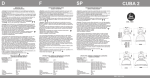
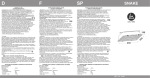
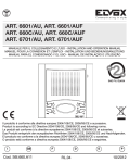
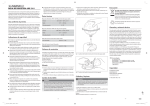
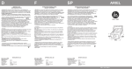
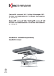
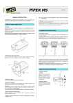
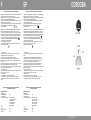
F
SP
INSTRUCTIONS D’INSTALLATION, USAGE ET ENTRETIEN
CORDOBA
INSTRUCCIONES DE INSTALACION, EMPLEO Y MANUTENCION
- Attention! La sécurité de l’appareil est garantie seulement avec l'usage approprié des
instructions suivantes, donc il est nécessaire de les conserver.
- Attention! Avant d'exécuter les connexions au réseau, pendant l'assemblage ou
substitution de la lampe, s'assurer d'avoir enlevé tension.
- Pour l'assemblage ou substitution de la lampe, exécuter les instructions données par
le constructeur, jointes à la lampe même.
- Dans l'usage de l’appareil, s'assurer que la distance entre la lampe et l'objet embrasé
ne soit pas inférieure à 1 mètre, comme indiqué dans
1m
le symbole relatif (ill. 4).
- Atención! La seguridad del aparato es garantizada sólo con el empleo apropiado de
las siguientes instrucciones, por tanto es necesario conservarlas.
- Atención! Antes de ejecutar las conexiones de red, durante el montaje o sustitución
de la lámpara, cerciorarse de haber sacado tensión.
- En el montaje o sustitución de la lámpara, ejecutar las instrucciones dadas por el
constructor, juntas a la lámpara misma.
- En el empleo del aparato, cerciorarse que la distancia entre lámpara y objeto
iluminado no sea inferior a 1 metro, como indicado en
1m
el relativo símbolo (fig. 4).
- Attention! Le verre de fermeture est toujours nécéssaire pour toutes les lampes à
«iodures métalliques» indépendamment du degré de protection de l’appareil.
- L’appareil peut être fixé directement au plafond au moyen d'un crochet en acier à être
inseré dans le piton en dotation. S'assurer que le crochet soit parfaitement fixé dans le
mur du plafond et que sa section soit min. de 28mm2 (par exemple: vis/goujon M6).
- Appareil apte à l'assemblage sur surfaces normalement inflammables .
- L’appareil est apte au fonctionnement seulement à l’intérieur.
- Appareil non pas apte à la liaison en cascade.
- Hauteur d’installation: n’importe quelle.
- Pendant l’installation et l’utilisation respecter les distances min. spécifiées en ill.4.
- Haute tension dans l’appareil.
- Atención! El cristal de protección es siempre necesario para todas las lámparas de
“alogenuros métalicos”, independientemente del grado de protección IP del aparato.
- El aparato puede ser instalado directamente a techo sobre gancho de acero, por
medio de la argolla incorporada. Cencionarse que el gancho esté bien enclavado al
techo. Sección mínima del gancho 28 mm2 (ejemplo clavija/tornillo M6).
- Aparato idóneo al montaje sobre superficies normalmente inflamables.
- El proyector es idóneo solamente al funcionamiento en interiores.
- Aparato no idóneo al enlace en catarata.
- Altura de instalación: cualquiera.-Durante la instalación y el empleo, respetar los
requisitos mínimos de distancia indicados en figura 4.
- Alta tensión al interior del aparato.
- Installation (fig.1).
1. Dévisser les 3 vis M5 qui fixent la plaque ronde en fer au corps de l’appareil.
2. Monter le crochet (fourni) et serrer bien l'écrou M8.
3. Monter le presse-étoupe (fourni) et serrer bien le contre-écrou.
4. A travers le presse-étoupe desserré, faire passer un câble type H05 RN-F
min.3x1mm2 ayant diamètre extérieur Ø=7÷12mm et le réunir aux bornes comme
montré en ill.2.
5. Repositionner la plaque en fer sur le corps de l’appareil en s’assurant que les bornes
soient positionnés près du presse-étoupe, ensuite revisser les 3 vis M5.
6. Tirer délicatement le câble à travers le presse-étoupe pour éviter qu’une partie trop
longue du câble même reste dans l’appareil.
7. Serrer le presse-étoupe.
8. Réunir réflecteur et corps en utilisant 4 vis M6. Serrer les vis d’une façon progressive,
selon ill.3, jusqu’à 1,2 Nm torque.
9. Insérer la lampe.
En cas d'utilisation du verre de fermeture (accessoire).
10. Réunir la queue de la chaîne du verre à l’anneaux positionné sur le corps.
11.Appuyez le verre au réflecteur et fixez-le au moyen de l'anneau de fermeture à
pression.
- Instalación (Fig.1).
1. Destornillar los 3 tornillos M5 que fijan la plancha redonda de hierro al cuerpo del
aparato.
2. Enganche el cáncamo (provisto) acoplándolo a la tuerca M8 firmemente.
3. Monte el prensaestopa (provisto) acoplándolo a la tuerca de cierre firmemente.
4. Entrar por el prensa-cable aflojado con un cable H05 RN-F min.3x1mm2 con
Ø=7÷12mm y conectarlo con el tablero porta-bornes según fig.2.
5. Reponer en su posición la plancha de hierro de manera que los bornes sean
posicionados cerca del prensa-cable, entonces atornillar los 3 tornillos M5.
6. Tirar el cable a través del prensa-cable porque no queda una parte demasiado larga
de cable dentro del aparato.
7. Apretar bien el prensa-cable.
8. Unir el reflector y el cuerpo utilizando 4 tornillos M6. Atornillar progresivamente los
tornillos, como descrito en fig.3, hasta 1,2 Nm de torsión.
9. Insertar la lámpara.
En caso de utilización del cristal protector (accesorio).
10. Conectar la cola de la cadena del vidrio al anillito situado sobre el cuerpo.
11. Ajuste el cristal al reflector y asegurelo por medio del anillo de cierre.
APPAREIL POUR LAMPES AUX VAPEURS D'HALOGENURES
ET SODIUM HAUTE PRESSION
APARATO POR LÁMPARAS A VAPORES DE ALOGENUROS
Y SODIO ALTA PRESIÓN
SÉRIE BASE: CORDOBA
Caractéristiques:
- Tension d'alimentation:
- Classe d'isolement:
- Puissance et courant de lampe:
- Cos ϕ:
- Douille:
- Degré de protection:
- Poids max:
230V~
I
250W 3A E40 SE/ME
250W 2,15A E40 ME 2,15A
250W 2,15A E40 QE
400W 4,4A E40 SE/ME
400W 3,25A E40 ME
400W 3,25A E40 QE
0,9
E40
IP23
Kg 10
SERIE BASE: CORDOBA
Características:
- Tensión de alimentación:
- Clase de aislamiento:
- Potencia y corriente de lámpara:
- Cos ϕ:
- Portalámpara:
- Clase de protección:
- Peso max:
DAL 1960
230V~
I
250W 3A E40 SE/ME
250W 2,15A E40 ME 2,15A
250W 2,15A E40 QE
400W 4,4A E40 SE/ME
400W 3,25A E40 ME
400W 3,25A E40 QE
0,9
E40
IP23
Kg 10
REV. 00 02/07
INSTALLAZIONE
INSTALLATION
A
E
B
F
A
GOLFARE
EYEBOLT
B
RONDELLA PICCOLA
SMALL WASHER
C
RONDELLA GRANDE
BIG WASHER
C
D
DADO M8
NUT M8
E
PRESSACAVO
CABLE GLAND
F
CONTRODADO M8
D
G
G
H
I
H
(COPPIA, TORQUE:
MIN 1,2NM)
(COPPIA, TORQUE:
N°4 VITI M6
MIN 1,2NM)
N°4 SCREWS M6
N°3 VITI M5
N°3 SCREWS M5
I
ANELLO PER CATENELLA VETRO
RING FOR GLASS CHAINE
L
CATENELLA VETRO
GLASS CHAINE
M
ANELLO DI CHIUSURA VETRO
CLOSING RING OF GLASS
L
M
Fig. 1
I
D
UK
ISTRUZIONI DI INSTALLAZIONE, USO E MANUTENZIONE
MONTAGE- UND WARTUNGSANLEITUNG
INSTALLATION, USE AND MAINTENANCE INSTRUCTIONS
- Attenzione! La sicurezza del proiettore é garantita solo con, l’osservanza delle
seguenti istruzioni, pertanto é necessario conservarle.
- Attenzione! Prima di eseguire le connessioni di rete, durante il montaggio o
sostituzione della lampada, assicurarsi di aver tolto tensione.
- Per il montaggio o sostituzione della lampada, eseguire le istruzioni date dal
costruttore allegate alla lampada stessa.
- Nell’uso del proiettore, assicurarsi che la distanza tra la lampada e l’oggetto
illuminato non sia inferiore a 1m come indicato
1m
nel relativo simbolo (fig.4).
- Warning! Safety of this floodlight is guaranteed only if the following instructions
are properly respected. It is therefore necessary to preserve them.
- Warning! Before connecting to the main network, during positioning or
replacement of lamps, ensure the tension has been disconnected.
- For positioning or replacement of lamps, follow the instructions given by the
lamp’s manufacturer, which should be supplied with the lamp itself.
- When the floodlight is on ensure that a minimum distance of 1m between the
lamp and the illuminated surface is respected as indicated by
1m
the relative symbol (pict. 4).
- Achtung! Die Sicherheit des Strahlers kann nur bei Befolgung der folgenden Anweisungen
und ihrer strikten Einhaltung gewährleistet werden. Bitte bewahren Sie diese Hinweise auf.
- Achtung! Bevor Sie die Netzanschlüsse durchführen, und während der Montage oder
des Leuchtmittelwechsels, vergewissern Sie sich, dass die Anlage ausgeschaltet ist.
- Beim Einsetzen des Leuchtmittels oder beim Leuchtmittelwechsel befolgen Sie die
Anweisungen des Leuchtmittelherstellers, die dem Leuchtmittel selber beigelegt sind.
- Wenn der Strahler eingeschaltet ist, stellen Sie sicher, dass der Abstand zwischen
dem Strahler und der zu beleuchtenden Fläche mindestens 1 m beträgt,
1m
wie es in dem Symbol (Bild 4) angezeigt ist.
- Attenzione! Il vetro di chiusura è sempre necessario per lampade a vapori di
alogenuri indipendentemente dal grado di IP dell’apparecchio.
- L’apparecchio può essere fissato direttamente a plafone mediante un gancio in acciaio
che si inserisca nell’apposito golfare predisposto. Accertarsi che il gancio sia ben fissato
a plafone ed abbia una sezione di almeno 28mm2 (es. un tassello a vite M6).
- L’apparecchio è idoneo al fissaggio su superfi normalmente infiammabili.
- Apparecchio idoneo esclusivamente all’uso in interni.
- L’apparecchio non é idoneo al funzionamento in cascata.
- Altezza di installazione qualsiasi.
- Durante l’installazione e l’uso attenersi alle posizioni di funzionamento ed alle distanze
minime indicate in fig. 4.
- Presenza di alta tensione nell’apparecchio.
- Warning! The glass diffuser is always necessary with any “metal halide” lamps
regardless of the IP protection degree of the fitting.
- This fitting can be installed directly on the ceiling through a steel hook to be inserted
into the eyebolt supplied. Ensure that the hook is safely fixed into the concrete ceiling.
Minimum hook’s section 28 mm2 (ex: screw dowel M6).
- The floodlight is suitable for installation on normally inflammable surfaces.
- Lighting fitting suitable for indoor use only.
- This fitting is not suitable for “tandem” installation.
- Installation height: any.
- During installation and use respect the minimum distance requirements indicated in
pic.4.
- High-tension inside the floodlight.
- Achtung! Bei Verwendung für alle Metaldampfleuchtmittel unabhängig von der
Schutzart der Leuchte, ist immer ein Abdeckglas notwendig.
- Die Leuchte kann mit Hilfe eines Deckenhakens direkt an der Decke befestigt
werden, indem Sie die Leuchte an der Ringöse des Leuchtenkopfes aufhängen.
Stellen Sie sicher, dass der Haken fest in der Decke verankert ist.
Minimumhakenquerschnitt 28mm2 (ex.M6).
- Der Strahler kann auf normal entzündbaren Oberflächen befestigt werden.
- Der Strahler ist nur für den Innenbereich geeignet.
- Der Strahler ist nicht für eine „Tandem-Installation“.
- Unbegrenzte Installationshöhe.
- Achten Sie darauf, dass die Leuchte unter Beachtung der Mindestabstände, wie
im Bild 4 angegeben, installiert und betrieben wird.
- Hochspannung im Leuchtengehäuse.
- Installazione (Fig.1).
1. Svitare le n°3 viti M5 che fissano la piastra tonda in ferro al corpo dell’apparecchio.
2. Applicare il golfare in dotazione serrando a fondo il dado M8.
3. Applicare il pressacavo in dotazione serrando a fondo il controdado.
4. Entrare dal pressacavo allentato con un cavo H05 RN-F min 3x1mm2 avente
diametro esterno Ø7÷12mm e cablarlo alla morsettiera come indicato in fig. 2.
5. Riposizionare la piastra tonda in ferro sul corpo dell’apparecchio in modo che la
morsettiera risulti vicina al pressacavo, quindi riavvitare le n°3 viti M5.
6. Tirare delicatamente il cavo dal pressacavo per quanto necessario ed evitare una
lunghezza eccessiva dello stesso all’interno dell’apparecchio.
7. Serrare a fondo il pressacavo.
8. Fissare la parabola al corpo dell’apparecchio mediante le n°4 viti da M6 ad esso
pre-avviate. Avvitare progressivamente le viti come indicato in fig.3 fino ad una coppia di
serraggio pari a 1,2Nm.
9. Inserire la lampada.
In caso di applicazione del vetro frontale (accessorio).
10. Fissare l’estremità libera della catenella del vetro all’apposito anello fissato al corpo
dell’apparecchio.
11. Applicare il vetro al riflettore fissandolo con l’anello di chiusura a pressione.
- Installation (pic.1).
1. Unscrew the 3 screws M5 that fix the round iron plate to the fitting’s body.
2. Couple the eyebolt (supplied) tightening the M8 nut deeply.
3. Couple the cable-gland (supplied) tightening the lock nut deeply.
4. Through the cable gland (loosen) enter a cable type H05 RN-F min. 3x1mm2 with
outer diameter Ø=7÷12mm and connect it to the terminal board as described in pic.2.
5. Put the round iron plate on the fitting’s body ensuring that the terminal board is placed
near the cable gland, then rescrew the 3 screws M5.
6. Extract softly the cable through the cable gland to avoid that a long section of the
cable itself is left inside the gear housing.
7. Tighten the cable gland.
8. Couple the reflector and the housing using the 4 screws M6 supplied. Tighten the
screws progressively, as described in pic.3, up to 1,2 Nm torque.
9. Insert the lamp.
In case of adoption of the glass cover (optional).
10. Connect the tail of the glass chain to the suitable ring on the lower part of the fitting’s
body.
11. Couple the glass to the reflector and tighten it by means of the closing pressure ring.
- Installation (Bild 1).
1. Lösen Sie die 3 Schrauben M5, die die runde Eisenplatte am Leuchtengehäuse
befestigen.
2. Verbinden Sie den Ösenbolzen (mitgeliefert) fest mit der M8 -Mutter
3. Verbinden Sie die Kabelverschraubung (mitgeliefert) fest mit der Kontermutter
4. Führen Sie durch den Kabeleinlass ein Kabel vom Typ H05 RN-F min. 3x1mm2 mit
einem Durchmesser von 7-12mm ein und schliessen Sie es an der Anschlussklemme,
wie in Bild 2.
5. Setzen Sie die Eisenplatte wieder in das Leuchtengehäuse ein und achten darauf,
dass die Anschlussklemme sich in der Nähe des Kabeleinlasses befindet. Schrauben
Sie die 3 Schrauben M5 wieder fest.
6. Ziehen Sie vorsichtig das Kabel durch den Kabeleinlass, um zu verhindern, dass ein
längerer Kabelabschnitt im Gehäuse der Leuchte verbleibt.
7. Ziehen Sie die Verschraubung des Kabeleinlasses fest an.
8. Befestigen Sie den Reflektor am Leuchtenkörper mithilfe der 4 M6. Schrauben.Ziehen
Sie die Schrauben kreuzweise mit einem Drehmoment von 1,2 Nm an (Bild 3).
9. Setzen Sie die Leuchtmittel ein.
Im Fall der Nutzung des Abdeckglases (Zubehör).
10. Hängen Sie die Kette des Glases in den Ring ein, der sich am unteren Teil des
Leuchtenkopfes.
11. Verbinden Sie das Glas mit dem Reflektor mit Hilfe der Ring-Druckverschluesse.
APPARECCHIO PER LAMPADE A VAPORI DI ALOGENURI
E SODIO ALTA PRESSIONE
FITTING FOR METAL HALIDE AND
HIGH-PRESSURE SODIUM LAMPS
STRAHLER FÜR METALLDAMPF UND
HOCHDRUCK-NATRIUM LAMPEN
cable H05 RN-F
Ø 7÷12mm2
L
SERIE BASE: CORDOBA
Caratteristiche:
- Tensione di alimentazione:
- Classe di isolamento:
- Potenza e corrente lampada:
N
min 1m
Fig. 2
ORDINE DI SERRAGGIO:
1-2-3-4
COPPIA DI SERRAGGIO:
1,2NM
1
3
ORDER OF TIGHTENING:
4
2
1-2-3-4
TORQUE SETTING:
1,2NM
Fig. 3
Fig. 4
- Cos ϕ:
- Attacco lampada :
- Grado di protezione:
- Peso max:
230V~
I
250W 3A E40 SE/ME
250W 2,15A E40 ME 2,15A
250W 2,15A E40 QE
400W 4,4A E40 SE/ME
400W 3,25A E40 ME
400W 3,25A E40 QE
0,9
E40
IP23
10Kg
BASIC SERIES: CORDOBA
Characteristics:
- Feeding tension:
- Insulation class:
- Lamp’s power and current:
- Cos ϕ:
- Lampholder:
- Protection degree:
- Weight max:
230V~
I
250W 3A E40 SE/ME
250W 2,15A E40 ME 2,15A
250W 2,15A E40 QE
400W 4,4A E40 SE/ME
400W 3,25A E40 ME
400W 3,25A E40 QE
0,9
E40
IP23
Kg 10
BASISSERIE: CORDOBA
Eigenschaften:
- Versorgungsspannung:
- Schutzklasse:
- Lichtleistung:
- Cos ϕ:
- Fassung:
- Schutzart:
- Gewicht max.:
230V~
I
250W 3A E40 SE/ME
250W 2,15A E40 ME 2,15A
250W 2,15A E40 QE
400W 4,4A E40 SE/ME
400W 3,25A E40 ME
400W 3,25A E40 QE
0,9
E40
IP23
10 kg