1
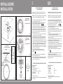
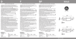
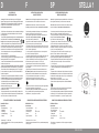
D
F
SP
STELLA 1
MONTAGE- UND
WARTUNGSANLEITUNG
INSTRUCTIONS D’INSTALLATION,
USAGE ET ENTRETIEN
INSTRUCCIONES DE INSTALACIÓN,
EMPLEO Y MANUTENCIÓN
- Achtung! Die Sicherheit des Strahlers kann nur bei Befolgung der
folgenden Anweisungen und ihrer strikten Einhaltung gewährleistet werden.
- Achtung! Bevor Sie die Netzanschlüsse durchführen, und während der
Montage oder des Leuchtmittelwechsels, vergewissern Sie sich,
dass die Anlage ausgeschaltet ist.
- Attention! La sécurité de l’appareil est garantie seulement avec l’observance
des instructions suivantes, donc il est nécessaire de les conserver.
- Atención! La seguridad del aparato es garantizada sólo con la observancia
de las siguientes instrucciones, por tanto es necesario conservarlas.
- Attention! Avant d’exécuter les connexions au réseau, pendant
l’assemblage ou substitution de la lampe, s’assurer d’avoir enlevé tension.
- Atención! Antes de ejecutar las conexiones de red, durante el montaje o
sustitución de la lámpara, cerciorarse de haber sacado tensión.
- Beim Einsetzen des Leuchtmittels oder beim Leuchtmittelwechsel befolgen
Sie die Anweisungen des Leuchtmittelherstellers, die dem Leuchtmittel
selber beigelegt sind.
- Wenn der Strahler eingeschaltet ist, stellen Sie sicher, dass der Abstand zwischen
dem Strahler und der zu beleuchtenden Fläche mindestens 0,3m
0,3 m
beträgt, wie durch das entsprechende Symbol angezeigt (Bild 1).
- Benutzen Sie den Strahler nie ohne Schutzglas und wechseln Sie das
Schutzglas bei Bruch oder wenn es Risse hat. In einem solchen Fall müssen
die 3 Schrauben, die den Rahmen auf dem unteren Körper befestigen
mindestens mit einem Drehmoment von 1,2Nm angezogen werden (Bild3 ).
- Bei dem Glas handelt es sich um ein temperaturwechselbeständiges,
bedrucktes Glas (Bild 2).
- Halten Sie das Glas frei von jeglichen Materialien.
- Das Glas ist nicht geeignet, Kraft- oder Schlageinwirkungen,die 0,5 Joule
übersteigen auszuhalten. Es ist nicht begehbar.
- Lassen Sie den Kabeleinlass unberührt, da sonst die Wasserdichtheit des
Strahlers verloren gehen kann.
- Nachdem Sie das Leuchtmittel positioniert haben, schliessen Sie den Leuchtenkörper
durch schrittweises Anziehen der 3 Schrauben M4 mit 1,2/1,4 Nm (Bild 4).
- Dieser Strahler ist für die Unterwassermontage bis 1,5m Tiefe geeignet.
Bei einer Installation in einer grösseren Tiefe ist die Wasserdichtheit des
Strahlers nicht garantiert.
- Es handelt sich um einen Niedervoltstrahler. Schliessen Sie den Strahler
nie direkt ans Netz an. Schliessen Sie das Versorgungskabel Niedervolt
12V~ über einen entsprechenden Transformator min. 20VA an (Bild 5).
- Der Strahler ist für den Innen- und Auflenbereich einsetzbar.
- Der Strahler ist für die direkte Installation auf normal
entflammbaren Oberflächen geeignet.
- Lassen Sie bei Installation in Zwischendecken und Decken um den
Strahler 200mm Freiraum.
- Die thermoplastische Box ist nicht wasserdicht (Bild 6). Installieren Sie in
der Box keine anderen elektrischen Komponenten (wie Anschlussklemmen
oder Trafos), sonder nur den Strahler und sein Kabel.
- Pour l’assemblage ou substitution de la lampe, exécuter les instructions
données par le constructeur, jointes à la lampe même.
- Dans l’usage de l’appareil, s’assurer que la distance entre la lampe et
l’objet embrasé ne soit pas inférieure à 0,3 mètre,
0,3 m
comme indiqué dans le symbole relatif (ill.1).
- L’appareil doit être utilisé seulement si complet de son verre de protection.
Il s’agit d’un verre pressé, trempé chemiquement (ill.2).
- Le remplacer tout de suite si vous relevez fêlures ou fentes. En ce cas, les
3 vis qui le fixent au corps antérieur doivent être serrées avec une torque de
1,2 Nm, de manière graduelle (ill.3).
- Le verre de protection n’est pas apte à résister aux chocs supérieurs à
0,5 Joule et il n’est pas apte à être piétiné.
- Ne pas altérer jamais le dispositif de serrage du câble (presse-étoupe). En
cas contraire l’appareil ne peut pas garantir l’imperméabilité à l’eau.
- Après avoir installé la lampe, serrer de manière progressive les 3 vis M4
de fermeture des corps avec une torque de 1,2÷1,4 Nm (ill.4).
- L’appareil est apte à l’immersion dans l’eau à une profondeur de
1,5 mètres maximum. Aux profondeurs supérieures l’imperméabilité à l’eau
n’est pas garantie.
- L’appareil est apte exclusivement au fonctionnement à basse tension.
Ne l’alimenter jamais avec tension directement du réseau électrique et
câbler les terminaux du câble d’alimentation à la sortie à basse tension
(12V~) d’un transformateur de juste puissance - min. 20VA (ill.5).
- Appareil apte au fonctionnement en extérieurs et intérieurs.
- Appareil apte à l’assemblage sur surfaces normalement inflammables.
- Para el montaje o sustitución de la lámpara, ejecutar las instrucciones
dadas por el constructor, suministradas con la lámpara misma.
- En el empleo del aparato, cerciorarse que la distancia entre la lámpara y
el objeto iluminado no sea inferior a 0,3 metros,
0,3 m
como indicado en el relativo símbolo (figura 1).
- El aparato tiene que ser utilizado sólo si completo de su vidrio de protección. Es un vidrio impreso, templado químicamente (figura 2).
- Reemplazarlo enseguida en el caso hay rajas o grietas. En este caso,
atornillar los 3 tornillos que lo fijan al cuerpo anterior con un momento torcedor de 1,2 Nm, de modo gradual (figura 3).
- El vidrio de protección no es idóneo a resistir a choques de energía
superior a 0,5 Joule, además no es idóneo a ser pisado.
- Nunca forzar el dispositivo de apretadura del cable (prensa-cable), de otra
manera el aparato no puede garantizar la impermeabilidad al agua.
- Después de haber insertado la lámpara, apretar de modo progresivo los
3 tornillos M4 de cierre de los cuerpos con un momento torcedor de
1,2 ÷1,4 Nm (figura 4).
- El aparato es idóneo a la inmersión en agua a una profundidad máxima de
1,5 metros. A profundidad superior la impermeabilidad al agua no es
garantizada.
- El aparato es idóneo exclusivamente al funcionamiento con baja tensión.
Non alimentar nunca con tensión de red. Cablear las terminales del cable
de alimentación a la salida en baja tensión (12V~) de un transformador de
adecuada potencia - min. 20VA (fig.5).
- Aparato idóneo al funcionamiento en exteriores y interiores.
- Aparato idóneo al montaje sobre superficies normalmente inflamables.
STRAHLER FÜR NIEDERVOLT HALOGENLAMPEN
APPAREIL POUR LAMPES HALOGENES BASSE TENSION
BASISSERIE: STELLA 1
Eigenschaften:
- Anschlussspannung:
- Schutzklasse:
- Lichtleistung:
- Leuchtmittelfassung:
- Schutzart:
12V~
III
max. 20W HS
G4
IP68
- Abmessungen: D. 122x31,5mm
- Durchmesser des Ausschnittes: D. 105mm (ohne thermoplastische Box)
- Gewicht: Kg 0,520
- Maintenir au moins 200 mm d’air libre autour du corps de l’appareil lorsque
il est encastré dans plafonds ou faux-plafonds (ill.1).
- Boîte thermo-plastique pour l’installation dans le mur, pas étanche (ill.6).
Ne pas y installer d’autres composants électriques (terminaux,
transformateurs...) que le projecteur et son câble.
SÉRIE BASE: STELLA 1
Caractéristiques:
- Tension d’alimentation :
- Classe d’isolement:
- Puissance lampe:
- Douille :
- Degré de protection :
12V~
III
max. 20W HS
G4
IP68
- Dimensiones : Ø 122 x 31,5 mm
- Diamètre du trou pour encastrement = Ø 105 mm (sans boîte thermo-plastique)
- Poids: Kg 0,520
DAL 1960
- Mantener al menos 200 mm de aire alrededor del cuerpo del aparato,
cuando es empotrado en techos o falso-techos (figura 1).
- Caja en material termo-plástico para instalación empotrada en mampostería,
non estanca (fig.6). No se pueden instalar en la caja otros componentes
eléctricos (bornes, transformador ...) que no sean el aparato y su cable.
APARATO PARA LÁMPARAS HALÓGENAS BAJA TENSIÓN
SERIE BASE: STELLA 1
Características:
- Tensión de alimentación :
- Clase de aislamiento:
- Potencia lámpara:
- Portalámpara:
- Clase de protección:
- Medidas:
12V~
III
max. 20W HS
G4
IP68
Ø 122 x 31,5 mm
- Diámetro hueco de empotramiento: Ø 105 mm (sin caja termo-plástica).
- Peso: Kg 0,520
REV. 00 12/03
I
INSTALLAZIONE
INSTALLATION
ISTRUZIONI DI INSTALLAZIONE
USO E MANUTENZIONE
ordine di serraggio
tightening sequence
1-2-3
1
coppia, torque: 1,2Nm
2
3
Fig. 3
ordine di serraggio
tightening sequence
1-2-3
1
Fig. 1
2
coppia, torque: 1,2Nm
sezione A-A
lato esterno faro,
external side of the fitting
area con pallinatura
in rilievo,
area with spot
embossing
lato interno faro,
internal side of the fitting
Superficie dove
appoggia la
guarnizione.
Mantenere
perfettamente
piana e liscia.
Surface where
the gasket is
lodged.
Keep perfectly
clean and
smooth.
3
Fig. 4
230V
min 20VA
- Attenzione! La sicurezza dell’apparecchio è garantita solo con l’uso
appropriato delle seguenti istruzioni, pertanto è necessario conservarle.
- Warning! Safety of this fitting is guaranteed only if the following instructions are properly respected. It is therefore necessary to preserve them.
- Attenzione! Prima di eseguire le connessioni di rete, durante il montaggio
o sostituzione di lampade, assicurarsi di aver tolto la tensione.
- Warning! Before connecting to the main network, during positioning or
replacement of lamps, ensure the tension has been disconnected.
- Per il montaggio o sostituzione della lampada, eseguire le istruzioni data
dal costruttore allegate alla lampada stessa.
- Nell’uso dell’apparecchio, assicurarsi che la distanza tra la lampada e
l’oggetto illuminato non sia inferiore a 0,3 m
0,3 m
come indicato nel relativo simbolo (Fig.1).
- L’apparecchio deve essere utilizzato solo se completo del suo schermo di
protezione. Trattasi di vetro stampato temperato chimicamente (Fig.2).
- Nel caso in cui si osservino incrinature o fessurazioni del vetro, esso va
immediatamente sostituito. In tal caso le N°3 viti che lo fissano al corpo
anteriore vanno serrate a fondo applicando un serraggio graduale delle viti
(momento torcente min 1,2 Nm - Fig.3).
- Lo schermo di protezione non é idoneo a subire urti di energia superiore a
0,5 Joule, inoltre non é idoneo a essere calpestato.
- Non manomettere mai il dispositivo di serraggio del cavo (pressacavo),
diversamente l’apparecchio non può garantire l’impermeabilità all’acqua.
- Dopo aver inserito la lampadina, serrare progressivamente e a fondo le
N°3 viti M4 di chiusura dei corpi (momento torcente min 1,2÷1,4 Nm - Fig.4).
- L’apparecchio é idoneo alla sommersione in acqua ad una profondità max
di 1,5 metri. A profondità superiori l’impermeabilità all’acqua non é garantita.
- L’apparecchio é idoneo esclusivamente al funzionamento con bassa
tensione, non alimentare MAI con tensione di rete, cablare i terminali del
cavo d’alimentazione all’uscita in bassa tensione (12V~) di un trasformatore
di potenza idonea _ MIN 20VA (Fig. 5).
- Apparecchio idoneo al funzionamento in interni ed esterni.
- Apparecchio idoneo al montaggio diretto su superfici normalmente
infiammabili.
- For positioning or replacement of lamps, follow the instructions given by
the lamp’s manufacturer, which should be supplied with the lamp itself.
- When the fitting is on, ensure that a minimum distance of 0.3m between
the lamp and the illuminated surface is respected,
0,3 m
as indicated by the relative symbol (picture 1).
- The fitting can be used only with its protective glass diffuser. It’s a printed
glass, chemically tempered (picture 2).
- In case cracks or other damages are found on the glass,
the glass must be immediately replaced. In such a case, the 3 screws that
fix it to the upper body must be gradually and firmly tightened (min 1,2 Nm
torque - pict.3).
- The protective glass is not supposed to resist to shocks exceeding
0.5 Joule and it is not suitable for walk-over installation.
- Do not ever temper with the cable gland (cable entry), otherwise the fitting
could loose its water-proofness.
- After positioning of the lamp tighte progressively and firmly the 3 screws
M4 closing the bodies (min 1.2÷1.4 Nm torque - picture 4).
- The fitting is suitable for under-water installation at a max. depth of 1.5m.
For deeper installations water-proofness is not guaranteed.
- The fitting is suitable to function at low tension only. Do not ever connect
it to the electrical network directly. Connect the terminals of the feeding
cable to the low tension (12V~) of a suitable transformer MIN.20VA (pict.5).
- The fitting is suitable for indoor and outdoor use.
- The fitting is suitable for direct installation on normally inflammable
surfaces .
- Mantenere almeno 200 mm di aria attorno al corpo dell’apparecchio
incassato in controssoffitti o plafoni (Fig.1).
- Scatola in materiale termoplastico, per fissaggio in muratura, non stagna
(Fig.6). Non collocarvi altri componenti elettrici oltre all’apparecchio con il
suo cavo (es. morsetti, trasformatori, ecc...).
APPARECCHIO PER LAMPADE ALOGENE BASSA TENSIONE
12V
SERIE BASE: STELLA 1
Caratteristiche
- Tensione di alimentazione :
- Classe d’isolamento :
- Potenza e tipo di lampada :
- Attacco lampada :
- Grado di protezione :
A
Fig. 2
INSTALLATION, USE AND
MAINTENANCE INSTRUCTIONS
- Keep at least 200 mm free space around the body of the fitting, in case it
is installed in false-ceilings or ceilings (picture 1).
- Thermo-plastic box for wall embedding, not water-proof (pict.6). Do not
install other electrical components in it (like terminals or transformers...) but
only the fitting and its cable.
ALIMENTATORE
TRANSFORMER
H05
A
UK
Fig. 5
Fig. 6
12V~
III
max 20W HS
G4
IP68
- Dimensioni: Ø 122x31,5 mm
- Diametro foro per incasso: Ø 105 mm (senza scatola in materiale termoplastico)
- Peso: 0,520 Kg
FITTING SUITABLE FOR LOW VOLTAGE HALOGEN LAMPS
BASIC SERIES: STELLA 1
Characteristics:
- Feeding tension:
- Insulation class:
- Lamp’s power:
- Lampholder:
- Protection degree:
12V~
III
max.20W HS
G4
IP68
- Dimensions: Ø 122x31,5 mm
- Diameter of fixing hole: Ø 105 mm (without thermo-plastic box)
- Weight: 0.520 Kg