1
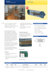
Catalog No.BKC0003-w
˙˙ Rheinland /
TUV
Berlin Brandenburg
Change from traditional exclusive production line to innovative
cell-manufacturing line !
A4 size desktop robot brings you a new
ideal manufacturing station.
DIN EN ISO 9001
JIS Z 9901
Certificate:09 100 5919
Anlagentechnik GmbH
ISO 14001, JIS Q 14001
Certificate-No.: 09 104 8118
Improvements
1. The program functions are enhanced.
2. The repetitive positioning precision: ±0.02 mm
3. The Z-axis-lead 2 mm specifications are added.
Discontinued
Koganei Desktop Robot
PAT. PEND.
The superior performance featured
in the compact "Creceed"
open up a new area of manufacturing.
3 axes robot
within an A4 size
working space
Discontinued
(smallest size for robot)
q
The compact and high-performance desktop robot "Creceed" completely re-establishes the
traditional image of an industrial robot.
Based on the operating technology gained through long experience in the pneumatics field,
KOGANEI has been achieving high productivity, versatility and the ability to meet the different
types of demands at the production site.
This all-round robot offers a full range of applications as an optimal solution to multi-needs, such
as flexible cell manufacturing. With no need for skilled operators, shorter debugging time and
minimial installation costs, it is suitable for a variety of process operations, from large
production lines to small workshop uses, laboratories, or even for the hobbyist.
Creceed is now available !
Discontinued
ct !"
pa
Com
"
Compact
Easy Operation
Flexible Use
Koganei Desktop Robot
w
The ideal method for expanding your
World's smallest size
Simple
Style
Z axis
Achieves micro-operation speed
The 2 mm lead
specifications are added.
X axis
Select either
100mm stroke or
200mm stroke
Easy to carry
Lightweight
5.5kg
Discontinued
Connector for external PC
RS232C connector
e
The program functions
are enhanced.
Connector for teaching box
Lights up to show the operation status
LED indicator
Compact
Easy Operation
Required setting space for the unit
is A4 size [210(W)× 300(D)mm].
This is also suitable for oneman working cells in a small
area where one person can
operates multiple units as well
as for the use in full-scale cell
manufacturing.
By adopting a precision sliding
screw, ± 0.02mm repeatability
is achieved.
Unit is portable, weighing only
5.5kg.
Even a beginner can operate the
robot easily, just by inputting
"moving points" and "parameters"
on a teaching box. A preprogrammed customized operation
software is available. Easy
program change and multitasking for several units are also
available.
Easy-operation
teaching box
(sold separately)
One-touch
operating box
manufacturing system.
Wiring to the motor with a one-touch
connector, for easy maintenance.
Rear of the body
I/O connector
Connector for Z & R
Connector for power supply
Connector for operating box
Connector for X & Y
Using precision sliding screw
±0.02mm
HighPrecision
T slot for parts attachment
(with square nut)
Y axis
54mm
:
Slim and versatile
as desktop
Rear of the body
Discontinued
INDEX
Safety precautions---------------t
Specifications------------------------ u
Attachments and options -------i
Body color matches work site environment
Dimensions ----------------------------o
Application specifications-------!2
CAUTION
Note: Always read the operating manual provided with the body and applications
before use. Also, be sure to read the "Safety Precautions" on p.t.
Flexible Use
Four different application
units are available such
as, dispensing adhesive,
grease or oil, fastening
for small size screw up
to M2Note, soldering and
cutting. On three axes
unit, three dimensional
linear and two dimensional
circular interpolation can
be utilized for more
effective
automation
solutions.
Dispensing
Unit
p.!4
Note: The special specifications can support up to M3.
Soldering
Unit
Screw Fastening
Unit
p.!4
p.!5
Cutting
Unit
p.!6
r
Safety Precautions (Creceed)
Before selecting and using products, please read all the Safety Precautions carefully to ensure proper product use.
The Safety Precautions shown below are to help you use the product safely and correctly, and to prevent injury or damage to
assets beforehand.
Observe these precautions along with the safety regulations of JIS B 8433 (Industrial Robot Safety Regulations).
The directions are ranked according to the degree of potential danger or damage: “DANGER,” “WARNING,” “CAUTION,” and “ATTENTION.”
DANGER
Expresses situations that can be clearly predicted as dangerous.
If the noted dangers are not avoided, they could result in death or serious injury.
They could also result in damage or destruction of assets.
WARNING
Expresses situations that, while not immediately dangerous, could become dangerous.
If the noted dangers are not avoided, they could result in death or serious injury.
They could also result in damage or destruction of assets.
CAUTION
Expresses situations that, while not immediately dangerous, could become dangerous.
If the noted dangers are not avoided, they could result in light or semi-serious injury.
They could also result in damage or destruction of assets.
ATTENTION
While there is little chance of injury, the content here is of points that should be observed for
appropriate use of the product.
■This product was designed and manufactured as parts for use in General Industrial Machinery.
■ For the selection and handling of the equipment, the system designer or other person with fully adequate knowledge and experience should always
read the "Safet Precautions," "Catalog," "User's Manual," and other relevant material before commencing handling. Making mistakes in handling is
dangerous.
■ In using this product, it is the customer's responsibility to verify and determine the compatibility of this product to customer’s systems.
■ After reading the Catalog, Instruction Manual, etc., always place them where they can be easily available for reference to users of this product.
■ If transferring or lending this product to another person, always attach the Catalog, Instruction Manual, etc., to the product where it is
easily visible, to ensure that the new user can use the product safely and properly.
DANGER
● Do not use for the purposes listed below:
1. Medical equipment related to the maintenance or management of
human lives or bodies.
2. Mechanical devices or equipment designed for the purpose of
moving or transporting people.
3. Critical safety components in mechanical devices.
This product has not been planned or designed for purposes that
require advanced stages of safety. It could cause injury to human life.
● Do not use in locations with or near dangerous substances such as
flammable or ignitable substances. It could ignite or burst into
flames.
● Do not enter the operating range of the machinery when the product
is in operation or in a state of operating readiness. The actuator can
move suddenly, possibly resulting in injury.
● Always install the product in a horizontal, flat, and secure location,
with plenty of margin for the operating space. Falling or toppling over
of the product, or abnormal operation, etc., could result in injury.
● Never attempt to rebuild the product. It could result in abnormal
operation leading to injury, electric shock, fire, etc.
● Never attempt inappropriate disassembly or assembly related to the
product's basic configurations, performance, or functions. It could
result in injury, electric shock, fire, etc.
● Do not splash water on the product. Splashing it with water, washing
it or using it underwater could result in malfunction of the product
leading to injury, electric shock, fire, etc.
● Do not place hands unnecessarily on the Y-axis table during power
failure or emergency stop. The 3-axis specification Creceed has no
brake mechanism on the Z axis, and a 2-axis table or an attached
device could descend under its own weight, resulting in injury.
● Do not allow the product to be thrown into fire. The product could
explode and release toxic gases.
● If the device emits abnormal noise or excessive vibrations, stop
operations at once. Continued operation could result in damaged
products, or in abnormal operation or runaway that results in injury.
● Do not sit on the product, place your foot on it, or place other objects on it.
Accidents such as falling and toppling over could result in injury.
Dropping the product may damage or break the product resulting in
abnormal, improper or erratic operation.
● When conducting any kind of operation of the product, such as
inspection, repair or replacement, always shut off the power supply
completely before starting.
Discontinued
WARNING
t
● Always use No.3 type grounding (grounding resistance of 100Ω or
less). Current leakage could possibly result in electric shocks or
malfunction.
● Before supplying electricity to the device, and before starting
operation, always conduct a safety check of the area of machine
operation. Careless supply of power could possibly result in electric
shocks, or in injury caused by contact with moving parts.
● Do not touch the terminal and the miscellaneous switches, etc.,
while it is plugged in. There is the possibility of electric shock and
abnormal operation.
● Do not scratch the robot cable, etc. If a cable has been damaged,
bent excessively, pulled, wound on something, put a heavy object
on it or has been pinched between objects, it can be the cause of
abnormal operation, electric shock, or fire due to poor conductivity
or a short circuit.
CAUTION
● Use a lift or other support tool to firmly support the product during
conveyance or mounting, or conduct the operation with a plural
number of people, etc., and always be careful to ensure human
safety.
● Do not use in atmospheres containing corrosive gases, flammable
gases, or flammable liquids. Resulting rust could weaken body
strength, while operating motor in such an environment risks an
explosion.
● Take sufficient shielding measures if using in the locations listed
below. Failure to take such measures could possibly result in
abnormal operation.
1. Locations subject to large electrical currents or magnetic fields
2. Locations subject to electric noise generated by static electricity, etc.
3. Locations that could be subject to radiation
● Mount the robot and controller in locations with low levels of dust
and dirt. Mounting in locations with large amounts of dust and dirt
could possibly result in abnormal operation.
● Do not mount in locations subject to large vibrations(0.5G or more).
Large vibrations transmitted to the product could possibly result in
abnormal operation.
General Precautions and Handling
CAUTION
ATTENTION
● When considering the possibility of using this product in situations
or environments not specifically noted in the Catalog or Instruction
Manual, or in applications where safety is a particularly important
requirement, such as airplane facility, combustion devices, leisure
equipment, and other places where human life or assets may be
greatly affected, take adequate safely precautions such as
application with enough margins or fail-safe measures for ratings
and performances. Please consult KOGANEI with any questions.
● Use a protective cover, etc., to ensure that people’s bodies do not come
into direct contact with the operating sections of mechanical devices, etc.
● Do not make the controls in a way that would cause work to fall
down during power outages. Make the controls so that the table,
workpiece, etc. cannot fall, if the mechanical device is subject to a
power outage or an emergency power shutdown.
● Do not use in locations under direct sunlight (ultraviolet), in
locations subject to dust, salt, or iron powder, or in ambient
atmospheres that contain organic solvents, phosphoric ester-based
hydraulic fluids, sulfur dioxide gas, chlorine gas, or acids. These
conditions could cause short-term functional shutdowns, sudden
performance failure, or a shortened operating life.
● For the wiring, check the Instruction Manual.
● When handling the product, wear protective gloves, safety glasses,
and safety boots, etc., to ensure safety.
● When the product has become unusable, or is no longer necessary,
dispose of it appropriately as industrial waste.
Read this before starting use.
Mounting
Observe the following precautions to keep the table moving
accuracy, and to ensure smooth sliding screw movement.
1. Install the robot in a horizontal, flat, and secure location.
2. Reserve adequate installation mounting space to ensure robot
rigidity.
Environment
1. Avoid using in locations where the robot and controller are
subject to dripping water or dripping oil, etc., or to large
amounts of dust.
2. Avoid using in locations subject to sulfuric acid, hydrochloric
acid, or other corrosive gases.
3. Avoid using in locations subject to strong vibrations or shocks.
Other
OTHER
● Always observe the following items.
KOGANEI cannot be responsible if these items are not
properly observed.
1. When using this product in systems, always use genuine
KOGANEI parts or compatible parts (recommended parts).
When conducting maintenance and repairs, always use
genuine KOGANEI parts or compatible parts (recommended
parts). Always observe the required procedures.
2. Do not attempt inappropriate disassembly or assembly
related to the product's basic configurations, performance,
or functions.
Before starting use, always read the instruction manual attached
to the robot and controller.
Discontinued
y
Robot
Orthogonal 3-axis type
DTR-CS3
Gantry 3-axis type
DTR-AS3
Orthogonal 2-axis type
DTR-CS2
Discontinued
Gantry 2-axis type
DTR-AS2
Specifications
Robot
Operating range(mm)
Maximum speed(mm/s)
Repeatability
Resolving power(mm)
Environment
DTR-AS3-3 DTR-ASL3-3 DTR-AL2-3
DTR-AL3-3 DTR-ALL3-3 DTR-CS2-3
DTR-CS3-3 DTR-CSL3-3
DTR-AS3-4 DTR-ASL3-4 DTR-AL2-4
DTR-AL3-4 DTR-ALL3-4 DTR-CS2-4
DTR-CS3-4 DTR-CSL3-4
X Note1
150
150
150
200
200
200
100
100
100
Y
180
180
180
180
180
180
200
200
200
Z
―
50
50
―
50
50
―
50
50
X・Y
200
200
200
200
200
200
200
200
200
―
200
70
―
200
70
―
200
70
±0.02
±0.02
±0.02
±0.02
±0.02
±0.02
±0.02
±0.02
±0.02
X・Y
2
2
2
2
2
2
2
2
2
Z
―
1
2
―
1
2
―
1
Z
(mm)
Maximum payload(kg)
DTR-AS2-3
DTR-AS2-4
X・Y(lead)
Z (lead)
0.015(6)
―
0.015(6)
0.015(6)
0.015(6)
0.005(2)
0.015(6)
―
Temperature
0.015(6)
0.015(6)
0.015(6)
0.005(2)
―
Humidity
0.015(6)
0.015(6)
0.005(2)
35∼90%
2-phase stepping motor, sliding screw
PTP, CP
Operating method
Axial control
Simultaneous 3-axis (4-axis : option) Note 2
Interpolation
3-dimensional linear interpolation
(0.45 ∼ 45mm/s)
, 2-dimensional circular interpolation (0.15∼15mm/s)
Teaching playback
Teaching method
Input/Output
Programming capacity
Point
Programming method
Serial Interface
Power source
16 points of I/O in each
General-purpose input:15, General-purpose output:13
(
Custom input:Start, Custom output:Ready, Busy and Pallet
1000 steps x 6 groups
1 step, 1 point
Code input
RS232C 1ch
External power supply box(INPUT AC85 ∼ 264V OUTPUT DC24V 2A)
Note 1:If using the Screw Fastening Unit or the Soldering Unit, the X axis should be a 200mm stroke.
2:The controller for the Soldering Unit shoud be a 4-axis specification.
1
0.015(6)
0∼40℃
Driving method
u
0.015(6)
)
Robot order code
Controller
200mm stroke Note1
150mm stroke
X-axis stroke
Number of axes
Orthogonal type
DTR
-AS
2-3
DTR
-AS
2-4
DTR
-AS
3-3
DTR
-AS
L33
DTR
-AS
3-4
DTR
-AS
L34
DTR
-AL
2-3
DTR
-AL
2-4
DTR
-AL
3-3
DTR
-AL
L33
DTR
-AL
3-4
DTR
-AL
L34
DTR
-CS
2-3
DTR
-CS
2-4
DTR
-CS
3-3
DTR
-CS
L33
DTR
-CS
3-4
DTR
-CS
L34
Gantry type
●
2-axis
●
3-axis controller
●
4-axis controller Note 2
●
●
●
3-axis
●
●
●
●
●
●
●
●
●
●
●
●
100mm stroke
●
●
●
●
●
●
●
●
●
●
●
●
●
●
●
●
●
●
Note 1:If using the Screw Fastening Unit with Z axis motor type or the Soldering Unit, always select the X-axis 200mm stroke product DTR-AL3-3, DTR-ALL3-3,
DTR-AL3-4 or DTR-ALL3-4.
If using the Screw Fastening Unit with air driven Z axis type always select the X-axis 200mm stroke products DTR-AL2-3 or DTR-AL2-4.
2:If using the Application of Soldering Unit, select the 4-axis controller (DTR-AL3-4 or DTR-ALL3-4). (Made-to-order product. Ask Koganei distributor for
delivery.)
System configuration diagram
Command list
Command Second
Input: 15 general purpose,
1 custom purpose
Output: 13 general purpose,
3 custom purpose
Externally controlled PC※
Power:
85 VAC to 264 V
I/O ※
connector
Explanation
Data
POINT
0**
Point
XY→ Z movement
POINT
1**
Point
ZI(virtual position) →XY→Z movement
POINT
2**
Point
ZO(virtual origin) →XY→Z movement
POINT
3**
―
ZI(virtual position) movement
POINT
4**
―
ZO(origin point height) movement
POINT
5**
―
Return-to-origin movement
POINT
6**
Point
R-axis movement
POINT
7**
Point
XYZ(absolute) movement
POINT
8**
Point
XYZ(incremental) movement
LINE
0**
Point
Linear interpolation movement
LINE
1**
LINE
200
―
Continuous interpolation storing end
LINE
300
―
Continuous interpolation operation
LINE
400
―
XYR simultaneous operation
LINE
500
CIRCLE
000
Point
PALET
0 0*
―
Pallet (number*) movement
PALET
1 0*
―
Pallet (number*) count-up output
SEQ
0**
―
IN** is in the ON wait status
SEQ
1**
―
IN** is in the OFF wait status
SEQ
2**
―
OUT** is ON
SEQ
3**
―
OUT** is OFF
SEQ
4##
―
Timer setting
SEQ
5**
―
Interpolation ON delay
SEQ
6** N o t e J=##
IN** is ON; an unconditional jump to the step No. ##
SEQ
7** N o t e J=##
IN** is OFF; an unconditional jume to the step No. ##
SEQ
8 0 0 N o t e J=##
An unconditional jump to the step No. ##
SEQ
9** N o t e J=##
IN** is ON; a CALL jump to the step No. ##
SEQ
9 1 6 N o t e J=##
An unconditional CALL jump to the step No. ##
SEQ
9 1 7 Note
―
Return
END
000
―
The program ends unconditionally
END
100
―
After 1-cycle operation, the program stops in the END step
END
200
―
The program operates repeatedly
Discontinued
Power supply box※
Operatiig box※
RS232C
cable※
Teaching box※
Creceed editor※
Personal computer※
Reference point Continuous interpolation storing start
Shift point Continuous interpolation shift operation
Circle movement
Note: Setting can be made only by the Creceed Editor; that is,
setting cannot be made by the Teaching Box.
※Accessory
※Option (sold separately)
※Prepared by customers
i
Attachments/Options
Attachments
Power supply box
DTRM-BB
Operating box
DTRM-OB
I/O connector
DTRM-CT
INPUT AC85 ∼ 264V OUTPUT DC24V
For manual operation of operation start or
emergency stop.
Connector for connecting to a personal computer,
solenoid valve, relay, or other external equipment.
■ Dimensions
■ Dimensions
240
53
26.5
70
φ18
φ8
50
50
Discontinued
75
(45)
Emergency stop switch
35
100
Group change switch
o
Origin, start-up, and temporary halt switch
Options
Teaching box
DTRP-TB
Personal computer support software:
Creceed Editor
Screw supplying unit
DTRM-SJ0001
For easy operation of parameter settings and
program input
Personal computer support tool for preprogrammed dedicated operations.
DTRP-SW-HTA (Japanese version)
DTRP-SW-HTC (English version)
Device for supplying screws to the "Screw
Fastening Unit".
DTRM-SJ0001 (for M1.4)
DTRM-SJ0002 (for M1.7)
DTRM-SJ0003 (for M2)
■ Dimensions
Sample program software
for applications
104
φ16.5
φ8
■ Dimensions
16.5 13.5
100
30
A sample program is available for each
application, and the sample program can be
used together with the Creceed Editor.
● For dispensing:
DTRP-SW-DPA
● For screw tightening (electrically powered):
153
Bracket for the screw supplying unit
DTRP-BKA
DTRP-SW-SDA
screw tightening (air): DTRP-SW-SDB
● For soldering:
DTRP-SW-SMA
●For cutting:
DTRP-SW-CTA
● For
■ Dimensions
158
16
3
122
162
3
73
40
124
60
40
106
73
15.5
4.5
2
63
125
1.5
82
Discontinued
132
7
120
52
21
!0
Dimensions
Remarks: The dimension diagram is different from the photo in the
catalog. The dimensions are correct, and the photo shows
the previous type.
(Unit mm)
39
150 stroke
(X axis)
112(Origin point)
42
26
4-M3 Depth 6
20
38
36
4-M3 Depth 6
10
50.5(Origin point)
42
310
DTR-AS2-3 (3-axis controller)
DTR-AS2-4 (4-axis controller, made-to-order product)
X axis : 150mm
180 stroke
(Y axis)
59.5
33
Gantry
2-axis
44
50
9
82
210
(301)
203.5
110
75
75
51
60
54
171
204.5
144.5
28
Discontinued
43.5
20
310
170
39
150 stroke
20
112(Origin point)
59.5 20
(X axis)
Gantry
3-axis
310
38
10
36
42
4-M3 Depth 6
50.5(Origin point)
DTR-AS3-3 (3-axis controller)
DTR-ASL3-3 (3-axis controller, Z-axis-lead 2 mm specifications)
DTR-AS3-4 (4-axis controller; made-to-order product)
DTR-ASL3-4(4-axis controller; Z-axis-lead 2 mm specifications; made-to-order product)
X axis : 100mm
180 stroke
(Y axis)
28
44
50
82
210
9
(301)
4-M3 Depth 6
26
50 stroke
(Z axis)
42
112(Origin point)
248.5
33
!1
43.5
79.5
230.5
75
203.5
110
75
51
60
54
171
360.5
138.5
38
20
170
20
Remarks: The dimension diagram is different from the photo in the
catalog. The dimensions are correct, and the photo shows
39
200 stroke
(X axis)
112(Origin point)
42
26
20
4-M3 Depth 6
36
4-M3 Depth 6
38
10
50.5(Origin point)
42
310
DTR-AL2-3 (3-axis controller)
DTR-AL2-4 (4-axis controller, made-to-order product)
X axis : 200mm
180 stroke
(Y axis)
59.5
33
Gantry
2-axis
44
50
71.5
69.5
210
(351)
203.5
110
137.5
62.5
51
60
54
171
204.5
144.5
28
Discontinued
43.5
20
310
20
112(Origin point)
200 stroke
(X axis)
20
39
170
59.5
Gantry
3-axis
4-M3 Depth 6
36
42
310
38
10
50.5(Origin point)
DTR-AL3-3 (3-axis controller)
DTR-ALL3-3 (3-axis controller, Z-axis-lead 2 mm specifications)
DTR-AL3-4 (4-axis controller; made-to-order products)
DTR-ALL3-4(4-axis controller; Z-axis-lead 2 mm specifications; made-to-order product)
X axis : 200mm
180 stroke
(Y axis)
28
44
50
71.5
69.5
210
(351)
26
50 stroke
(Z axis)
42
112(Origin point)
248.5
4-M3 Depth 6
360.5
138.5
38
43.5
79.5
230.5
203.5
110
62.5
51
60
54
171
33
137.5
20
170
20
!2
Remarks: The dimension diagram is different from the photo in the
catalog. The dimensions are correct, and the photo shows
100 stroke 112(Origin point)
(X axis)
55
42
39
26
38
4-M3 Depth 6
200 stroke(Y axis)
60
4-M3 Depth 1.6
105
133
310
117
DTR-CS2-3 (3-axis controller)
DTR-CS2-4 (4-axis controller, made-to-order product)
38
33
Orthogonal
2-axis
112(Origin point)
(Unit mm)
38
20
6
28
40
210
35
28
242
72
243
110
120
100 stroke
(X axis)
39
112(Origin point)
38
4-M3 Depth 1.6
117
Orthogonal
3-axis
DTR-CS3-3 (3-axis controller)
DTR-CSL3-3 (3-axis controller, Z-axis-lead 2 mm specifications)
DTR-CS3-4 (4-axis controller; made-to-oreder product)
DTR-CSL3-4(4-axis controller; Z-axis-lead 2 mm specifications; made-to-order product)
200 stroke(Y axis)
28
45.5
133
60
38
310
171.5(Origin point)
170
51
54
51
Discontinued
20
20
6
40
210
35
(251)
26
42
50 stroke
(Z axis)
4-M3 Depth 6
!3
107
20
170
120
72
28
242
186.5
51
54
110
51
203.5
287.5
399.5
112(Origin point)
33
(417)
203.5
192
(251)
107
(417)
Dimensions
Applications
Attention For the detailed specifications, external dimensions,
handling requirements, and safety precautions for each
unit, see the operating manuals provided with each unit.
Dispensing Unit
DTRU-DPA
●Optimum for dispensing or applying such as grease or adhesives.
●Uses a no-taper syringe and double wiper piston construction
for stable liquid dispensing.
Specifications
X axis
150mm
Operating range Y axis
180mm
Valve box
Syringe/Piston
Z axis
50mm
Dispensing pressure range
0.02∼ 0.3MPa
Dispensing time range
0.1 ∼ 9.9Sec
Power supply
24VDC
Size (cc)
3 pcs. each of 10 and 30 (applicable to UV)
Syringe adaptor Size (cc)
Syringe cap
Size (cc)
(needle length 12.7mm)
3 pcs. each of 10 and 30
6 pcs.
Syringe end caps
Needle nozzle
1 pce. each of 10 and 30 (connecting tube, 0.9m)
Gauge size
2 pcs. each of 18, 20, 21, 22, 23 and 25
Optional item
●Sample program software:DTRP-SW-DPA
Maintenance parts
Discontinued
●Valve box ●Syringe ●Syringe adaptor ●Needle nozzle ● Piston
● Syringe cap ● Syringe end cap ● O ring
Creceed body sold separately.
Attention
Dispenser conditions can be changed depending on the environment, materials
used, etc. We cannot, therefore, guarantee dispensing quality. For dispensing
quality, the user should always ensure the quality by his application.
Screw Fastening Unit (Z-axis : motor)
DTRU-SDA
● Work in combination with a screw supplying unit realizes
automatic screw fastening.
Specifications
X axis
200mm
Operating range Y axis
180mm
Z axis
50mm
Applicable screw size M1 ∼ M2 (up to M3 with special)
Applicable screw types Depends on type of screw supplying unit
Controller power supply voltage 100VAC±5% 50/60Hz
Controller power consumption 180W
Driver
Bit
Mouthpiece
Valve box
2 pcs, H4-#0, 20×60
1 each of 01 (M1.4), 02 (M1.7), 03 (M2.0),
Pan head type 1 cross-slotted screw
Air pressure
0.4 ∼ 0.7MPa
Power supply voltage
24VDC
If using the Screw Fastening Unit, select 200mm stroke
Attention robot (DTR-ALL3-3, DTR-ALL3-4) as the X-axis
Optional item
●Sample program software:DTRP-SW-SDA
●Screw supplying unit:DTRM-SJ0001, DTRM-SJ0002, DTRM-SJ0003
Maintenance parts
Creceed body sold separately.
●Driver ●Controller ●Bracket ●Valve box (for driver) ●Bit
●Mouthpiece
Attention
Screw fastening conditions can be changed depending on the environment,
materials used, etc. Koganei cannot, therefore, guarantee screw fastening
quality. For screw fastening quality, the user should always ensure the quality
by his application.
!4
Applications
Screw Fastening Unit (Z-axis : pneumatics)
DTRU-SDB
●Screw fastening unit of this type uses an air cylinder for the Z
axis.
Specifications
Operating range
X axis
200mm
Y axis
180mm
Applicable screw size M1 ∼ M2
Applicable screw type Depends on type of screw supplying unit
Controller power supply voltage 100VAC±5% 50/60Hz
Driver
Controller power consumption 180W
Bit
Mouthpiece
Air pressure
Valve box
2 pcs, H4-#0, 20×60
1 each of 01 (M1.4), 02 (M1.7), 03 (M2.0),
Pan head type 1 cross-slotted screw
0.4 ∼ 0.7MPa
Power supply voltage 24VDC
Z-axis cylinder unit Cylinder model
ARS16×30
When using the Screw Fastening Unit, select 200mm
Attention 2-axis robot (DTR-AL2-3, DTR-AL2-4) as the X-axis
Optional item
Discontinued
●Sample program software:DTRP-SW-SDB
●Screw supplying unit:DTRM-SJ0001, DTRM-SJ0002, DTRM-SJ0003
Maintenance parts
Creceed body sold separately.
●Driver ●Controller ●Bracket (for driver) ●Valve box
Attention
Soldering Unit
DTRU-SMA-□
Screw fastening conditions can be changed depending on the environment,
materials used, etc. Koganei cannot, therefore, guarantee screw fastening
quality. For screw fastening quality, the user should always ensure the quality
by his application.
● For space-saving soldering.
Specifications
X axis
200mm
Operating range Y axis
180mm
Z axis
50mm
Power supply for heat controlling unit AC100V 50/60Hz
Heat controlling range 200 ∼ 450℃
Solder diameter (mm)
Solder
Soldering method
DTRU-SMA-01
0.5, 0.6
DTRU-SMA-02
0.8
DTRU-SMA-03
1.0, 1.2
DTRU-SMA-04
1.6
Point soldering
Line soldering
Supplying air pressure 0 ∼ 0.7MPa
Valve box
Discharging pressure range 0.02 ∼ 0.5MPa
Power supply voltage DC24V
When using the Soldering Unit, select X-axis as 200mm
Attention DTR-ALL3-4(4-axis controller).
(Made-to-order product. Ask Koganei distributor for delivery.)
Creceed body sold separately.
Optional item
●Sample program software: DTRP-SW-SMA
Maintenance parts
●Soldering iron head & feeding unit ●Heat controlling unit
●Bobbin bracket ●Cleaning unit ●Valve box
!5
Attention
Soldering conditions can be changed depending on the environment,
materials used, etc. Koganei cannot, therefore, guarantee soldering quality.
For soldering quality, the user should always ensure the quality by his
application.
Cutting Unit
DTRU-CTA
Specifications
Operating range
DC brushless
spindle motor
X axis
100mm
Y axis
150mm
Z axis
50mm
Revolutions
20,000rpm
Collet diameter
φ2mm
Controller power supply voltage 100VAC 50/60Hz
Controller power consumption 75W
Motor output
30W
Optional item
●Sample program software:DTRP-SW-CTA
For dust collection methods, static elecricity removal, and other items, consult us.
Maintenance parts
●Spindle motor ●Controller ●Bracket (for spindle motor)
Attention
Cutting conditions can be changed depending on the environment, materials
used, etc. Koganei cannot, therefore, guarantee cutting quality. For cutting
quality, the user should always ensure the quality by his application.
Discontinued
Creceed body sold separately.
!6
Special specifications of the robot and applicaion unit
Creceed of special specifications often ordered is handled as semi-standard products and is prepared in advance.
When ordering Creceed of special specifications from us, contact the nearest sales office.
Robot
Screwfastening
unit
Order code
Special specifications
DTR-CS3-3-9W
Rigidness-enhanced orthogonal type
DTR-AL3-160-3-12W
Stand height is 160 mm
DTR-AL3-210-3-12W
Stand height is 210 mm
DTR-AL3-260-3-12W
Stand height is 260 mm
DTR-AL3-160-4-12W
Stand height is 160 mm; 4 axes controller type
DTR-AL3-210-4-12W
Stand height is 210 mm; 4 axes controller type
DTR-AL3-260-4-12W
Stand height is 260 mm; 4 axes controller type
DTR-AS3-160-3-13W
Stand height is 160 mm
DTR-AS3-210-3-13W
Stand height is 210 mm
DTR-AS3-260-3-13W
Stand height is 260 mm
DTR-AS3-160-4-13W
Stand height is 160 mm; 4 axes controller type
DTR-AS3-210-4-13W
Stand height is 210 mm; 4 axes controller type
DTR-AS3-260-4-13W
Stand height is 260 mm; 4 axes controller type
DTRM-S0001-5W
Driver for M2.6
DTRM-S0001-6W
Driver for M3.0
DTRU-SDA-1W
Z-axis electrically powered for M2.6 screw tightening
DTRU-SDB-2W
Z-axis pneumatic type for M2.6 screw tightening
DTRU-SDA-3W
Z-axis electrically powered for M3.0 screw tightening
DTRU-SDB-4W
Z-axis pneumatic type for M3.0 screw tightening
Discontinued
Remarks: The cutting unit having the specifications of 40,000 rpm can be
manufactured. When you need such a cutting unit, contact our sales office.
Note: Products of these special specifications might be different from the
standard ones in delivery, price, dimensions and life cycles, consequeutly
before ordering these products, be sure to contact our sales office for
confirmation of such differences.
!7
Discontinued
Revised points
First edition
P8
The code of the screw supply unit is added.
P12
In the dispense unit specifications table, the valve box discharging
pressure setting range is changed to 0.02∼0.3 MPa.
P12, 13 In the screw tightening unit specifications table, the driver bit is
changed to H4-#0 (2.0×60) (2 pieces).
P13
In the soldering unit specifications table, the diameter of the solder
in the solder specifications is written for each model.
P14
In the specifications table, the motor output is added.
P7
In the specifications of the robot, power 24 VDC is changed to 85
VAC∼264 VAC.
P8
INPUT 100V AC of the power supply box (accessory) is changed to
85 VAC∼264 VAC.
P3, 4, 12, 13 The photos of the following are changed: teaching box,
dispensing unit, screw fastening unit (2-axis electrically powered),
soldering unit, and cutting unit.
P8
The photos of the following are changed: power supply box,
personal computer support software.
The dimensions of the screw supply unit is added.
The bracket for the screw supply unit are added.
P9, 10 The dimensions, extension lines, and figures are added.
P7
In the specifications table for the robot, the interpolation speed of
the interpolation function is changed.
P3
The repeatability is changed from ±0.05 mm to ±0.02 mm.
The X-axis stroke is changed from 100 mm to 150 mm.
P7
The following models are added: DTR-ASL3-3, DTR-ASL3-4, DTRALL3-3, DTR-ALL3-4, DTR-CSL3-3, and DTR-CSL3-4.
P9, 10, 11
The dimensions and the notation are changed.
P10
Personal computer support software is provided in Japanese or
English versions.
和文カタログ No.C2141u
!8
Your inquiry to "Creceed"
FAX. 81-3-5286-2763
If you have inquiry, please fax us.
Company name
Office or plant name
Section
Your products
Your title
Your name
Your responsibility
Zip code
Address
FAX
Phone
E mail
How did you know
the "Creceed" ?
Discontinued
Heading of inquiry
Your inquiry
URL
http://www.koganei.co.jp
E-mail: [email protected]
OVERSEAS DIVISION
Shinjuku-TX Bldg., 1-3-21 Ohkubo, Shinjuku-ku, Tokyo 169-0072, Japan
Tel: 03-5272-8781 Fax: 03-5286-2763
LOS ANGELES REPRESENTATIVE OFFICE
3838 CARSON STREET, SUITE 329, TORRANCE, CA 90503 U.S.A.
Tel: 310-792-0471 Fax: 310-792-0462
SINGAPORE REPRESENTATIVE OFFICE
Block 1001, Jalan Bukit Merah #06-08, Singapore 159455
Tel: 2736461 Fax: 2752551
1/‘01 30 CHS
©KOGANEI CORP. PRINTED IN JAPAN
RECYCLED PAPER