1
1
- Caratteristiche tecniche ed estetiche possono essere soggette a modifiche senza preavviso.
UBICAZIONE CODICE IDENTIFICATIVO VEICOLO
Il numero identificativo del veicolo è stampato nella parte anteriore
del telaio sul lato destro del canotto dello sterzo.
ITALIANO
INDICE
1- ISTRUZIONE PER IL MONTAGGIO PRIMA DELLA MESSA IN PISTA
2- TRASPORTO DEL VEICOLO
3- OPERAZIONI DA SVOLGERSI PRIMA DELLA MESSA IN PISTA DELLA MINICROSS/MINIMOTARD
4- RODAGGIO DEL VEICOLO
5- SPEGNIMENTO DEL MOTORE
6- GUIDA SICURA: CONDIZIONI D’USO DELLA MINICROSS/MINIMOTARD
7- MANUTENZIONE, INTERVENTI E REGOLAZIONI
8- ISPEZIONE E CONTROLLI DI MESSA A PUNTO E PREPARAZIONE GARA
9- CARATTERISTICHE TECNICHE
10- RICAMBISTICA
11- RIMESSAGGIO
12- FORMAZIONE E INFORMAZIONE
PREMESSA
ALL’INTERNO DI QUESTO MANUALE VENGONO SEGNALATI,
ANCHE RIPETENDOCI, GLI EVENTI PERICOLOSI A CUI PRESTARE
PARTICOLARE ATTENZIONE E LE AVVERTENZE DA SEGUIRE PER
UN CORRETTO UTILIZZO DELLA MINICROSS/MINIMOTARD.
PER QUANTO RIGUARDA LA MANUTENZIONE DEL MOTORE
NON VENGONO DATE INDICAZIONI SPECIFICHE; TALI
OPERAZIONI SUL MOTORE DOVRANNO ESSERE ESEGUITE IN
OFFICINE SPECIALIZZATE.
Vi preghiamo di leggere attentamente questo libretto d’uso e
manutenzione prima di mettervi alla guida del Vostro veicolo.
Questo manuale contiene informazioni importanti che vi
aiuteranno ad evitare a Voi stessi, a cose e persone spiacevoli
rotture, lesioni personali gravi e incidenti anche mortali.
La perfetta messa a punto e la totale conoscenza del Vostro
veicolo prima della partenza assicura sicurezza e tranquillità per
godere fino a fondo il piacere della Vostra guida in fuoristrada.
AVVERTIMENTO IMPORTANTE
QUESTA MOTOCICLETTA È STATA DISEGNATA SOLO PER USO
COMPETITIVO. È VIETATO L’UTILIZZO SU OGNI TIPO DI STRADA
PUBBLICA. LE LEGGI VIGENTI PERMETTONO L’USO DI QUESTA
MOTOCICLETTA SOLO IN GARE ORGANIZZATE O
AVVENIMENTI SPORTIVI SU PISTE CHIUSE E PRIVATE E ALLA
PRESENZA DI ENTI PREPOSTI ALLA SICUREZZA
(AUTOAMBULANZA, VIGILI DEL FUOCO, ECC.).
DIVIETO DI TRASPORTO DI PASSEGGERI E/O COSE
SOLO PILOTA SENZA PASSEGGERO. Questa minicross/
minimotard è stata disegnata per l’uso col solo pilota.
RICORDA
L’uso di questo veicolo da parte di minori di anni 18 deve
avvenire sempre sotto la tutela di persone adulte e competenti.
LEGGERE QUESTO MANUALE CON ATTENZIONE.
All’interno del manuale vengono segnalate particolari situazioni
relative a pericoli, eventi e situazioni pericolosi dovuti all’uso e alla
manutenzione della minicross/minimotard: ai sensi del punto 3
della Norma UNI EN 1050:1998 sono così definiti:
DANNO: Lesione fisica e/o danno alla salute o ai beni
EVENTO PERICOLOSO: evento che può causare danno
Prima di qualsiasi utilizzo della minicross/minimotard o operazione
di manutenzione sulla minicross/minimotard stessa assicurarsi di
aver ben compreso quanto prescritto nel manuale prestando
particolare attenzione alle fasi segnalate con il simbolo di
EVENTO PERICOLOSO o AVVERTENZA.
IMPORTANTE. Questo manuale deve essere considerato una
parte permanente della minicross/minimotard e deve rimanere con
essa qualora venisse rivenduta.
ITALIANO
AVVERTENZA. La minicross/minimotard Polini è una
motocicletta da corsa ad alte prestazioni che utilizza tutti gli ultimi
ritrovati della tecnologia per motocross. Questa minicross/
minimotard deve essere utilizzata in gara solo da piloti esperti.
UTILIZZO DI DISPOSITIVI DI PROTEZIONE E
PRESCRIZIONI DI SICUREZZA
1- La gran parte dei decessi per incidenti motociclistici sono dovuti a ferite al capo. Indossare SEMPRE il casco OMOLOGATO. Utilizzare ginocchiera e para gomiti (certificati ai sensi del norma EN 1621-1 / 1997). Utilizzare abiti protettivi o tute. Utilizzare calzature chiuse e idonee con suola resistente alle abrasioni.
2- Il sistema di scarico diviene estremamente caldo durante l’uso e rimane tale per un certo tempo anche dopo. Non toccare mai le parti calde del sistema di scarico. Indossare abiti che coprano completamente le gambe.
3- Non indossare abiti larghi che si possano impigliare nelle leve di comando, nei poggia piedi, nella catena di trasmissione o nelle ruote.
4- Rispettare la natura.
AVVERTENZA
MODIFICHE DELLA MINICROSS/MINIMOTARD O LA
RIMOZIONE DI PARTI ORIGINALI POSSONO RENDERE
IL VEICOLO INSICURO O ILLEGALE. OTTEMPERARE A
TUTTE LE NORMATIVE NAZIONALI E LOCALI.
QUESTO MOTOCICLO È PROGETTATO PER UN PILOTA
DI PESO INFERIORE A:
- 45 Kg. PER IL MODELLO X1
- 50 Kg. PER IL MODELLO X3
- 55 Kg. PER IL MODELLO X5
- 80 Kg. PER IL MODELLO MINIMOTARD
La Polini Motori raccomanda per la Vostra sicurezza di avere sempre
il meglio per il Vostro veicolo e di esigere esclusivamente ricambi
originali Polini Motori. Al fine di conoscere la vera identità del
Vostro veicolo annotate da subito qui di seguito le sue generalità:
MODELLO: ..................................................................................
CILINDRATA: ...............................................................................
PNEUMATICI: Ant. .............................. Post. ...............................
N.TELAIO: ...................................................................................
CODICE: 144.000. ......................................................................
PESO: .........................................................................................
N.
N.
N.
N.
N.
1
2
1
1
2
3- Tale operazione riguarda soltanto i modelli X3 e X5. Si inizierà con il montaggio dell’ammortizzatore posteriore, utilizzando la vite a testa esagonale M10x80, i due distanziali M10.5 e le due rondelle con il dado M10, lasciando una rondella dal lato del dado ed una dal lato della vite; particolari che troverete già montati nella propria sede nel forcellone (foto 2-3).
4- Da questo punto in avanti le operazioni devono essere eseguite AL NUOVO PROPRIETARIO
Scegliendo una minicross/minimotard Polini come vostra nuova
motocicletta siete entrati a far parte di una distinta famiglia di
proprietari e piloti di motociclette.
Questo nuovo modello è stato disegnato in modo da essere il più
competitivo possibile. Il motocross è comunque uno sport fisico che
richiede di più che una buona motocicletta.
Per ottenere buoni risultati è necessario essere in buone condizioni
fisiche ed essere un pilota abile. Per ottenere i migliori risultati
possibili, allenarsi diligentemente per il condizionamento fisico ed
esercitarsi di frequente. Lo scopo di questo manuale consiste
nell’aiutarvi ad ottenere la massima soddisfazione possibile dalla
vostra minicross/minimotard Polini, soddisfazione ottenuta tramite
le prestazioni della motocicletta stessa ed i successi ottenuti in gara.
Copri pedana sinistra superiore
Pomello laterale Ø35
Pomello laterale Ø55
Bussola pomello Ø55 8x12x11
Bussola pomello Ø35 6x10x7
2
1. ISTRUZIONE PER IL MONTAGGIO PRIMA DELLA
MESSA IN PISTA
La moto che vi si presenterà all’apertura della scatola d’imballo non
è pronta all’uso ma parzialmente smontata per motivi di trasporto.
Al momento del disimballo si dovranno effettuare una serie di
operazioni di montaggio e di controllo, seguendo le nostre istruzioni,
al fine di poter ottenere il prodotto nella sua giusta conformazione
e pronto all’uso. Per una migliore funzionalità di montaggio vi
consigliamo di procedere nel seguente ordine:
1- Togliere la moto dalla scatola (foto 1).
1
2- All’interno della scatola è contenuto
composto:
Minicross/minimotard Polini
Rondella 6X18X1
Fascetta in plastica
Molla per pedana
Vite TCEI M8X40
Vite TB M6X16
Pedana destra
Pedana sinistra
Dado autoblocc. M8
Vite TCEI M8X30
Cavallotto manubrio
Manubrio con paracolpi
Ruota anteriore con disco
Parafango anteriore
Manuale d’uso e manutenzione
Certificato di conformità CE
un kit di montaggio così N.
N.
N.
N.
N.
N.
N.
N.
N.
N.
N.
N.
N.
N.
N.
N.
1
4
1
2
2
4
1
1
2
4
2
1
1
1
1
1
Per il modello minimotard, saranno presenti questi altri componenti:
Rondella 6x13x1,5
N. 2
Rondella 8x17x1,2
N. 1
Vite M6x20 TCEI
N. 1
Vite M5x20 TPSEI
N. 2
Vite M8x20 TCEI
N. 1
Copri pedana destra inferiore
N. 1
Copri pedana destra superiore
N. 1
Copri pedana sinistra inferiore
N. 1
3
su tutti i modelli minicross/minimotard. Allargare le pastiglie del freno della pinza anteriore aiutandosi ad esempio con una chiave inglese (foto 4).
4
5- Procedete con il montaggio della ruota anteriore utilizzando l’apposito perno; inserite il distanziale in dotazione montato verso il lato del disco (foto 5).
6- Infilare il perno ruota e chiudere con chiave dinamometrica (vedi tabella 9.1) (foto 6).
ITALIANO
2
3
5
freno anteriore. Montare ora il
manubrio fissandolo alla forcella tramite i due appositi cavallotti e le quattro viti a testa cilindrica con esagono incassato M8X30 (vedi tabella 9.1) (foto 9).
confezione.
12
RICORDA. Una regolare manutenzione come descritta nel manuale
16
9
-
-
13 6
11- Smontare il comando dell’acceleratore, infilare il filo come nella
foto 10 e richiudere il coperchietto (vedi paragrafo 7.8).
10
Chiudere il bullone di fissaggio del perno con chiave dinamometrica (vedi tabella 9.1) (foto 7).
14
7
12- Posizionare la leva del freno anteriore fissando il cavallotto con le apposite viti (foto 11).
11
9- Montare il parafango con le 4 apposite viti e rondelle in dotazione (foto 8) e controllare il serraggio della vite della tabella porta numero anteriore.
10- Tagliare la fascetta d’imballaggio della pompa del
Rimuovere il tappo di protezione (foto 15) per l’uscita
accidentale dell’olio e riutilizzando la guarnizione tolta da questo, avvitare il depressore di sfiato dell’olio che troverete in quella posizione attaccato con una fascetta ad un tubo collegato sotto il serbatoio. Controllare poi il livello dell’olio del motore (vedi paragrafo 7.3) (foto 23).
Riempire il serbatoio di carburante (vedi paragrafo 7.14)
15
8
2. TRASPORTO DEL VEICOLO
Per un corretto e sicuro trasporto del veicolo dal luogo del
rimessaggio alla pista in cui verrà utilizzato è necessario:
- Accertarsi che il serbatoio sia vuoto per evitare possibili perdite;
- Posizionare la minicross/minimotard su un piano orizzontale del mezzo con cui verrà effettuato il trasporto;
- Posizionare la minicross/minimotard sul cavalletto e fissandola mediante cinghie o funi assicurarsi che durante il trasferimento resti sempre in posizione verticale.
AVVERTENZA. Non effettuare mai il trasporto della moto con
il serbatoio della benzina pieno o con le parti di scarico o del
motore calde.
16
17-
8- Procedere al gonfiaggio dei pneumatici.
ANTERIORE
POSTERIORE
1,0 BAR - 14,5 PSI
1,0 BAR - 14,5 PSI
e un controllo prima di utilizzare il veicolo sono essenziali.
Se occorre un intervento di manutenzione straordinaria o si
rendono necessarie delle riparazioni rivolgetevi al Vostro
concessionario POLINI MOTORI. A causa del continuo sviluppo di
questi veicoli e dei diversi aggiornamenti tecnici durante la
progettazione, in alcuni casi potrebbero rilevarsi discordanze tra il
veicolo effettivo, le illustrazioni ed il testo di questo manuale.
I particolari originali che la POLINI MOTORI fornisce come
ricambio sono dello stesso materiale ed hanno subìto il medesimo
ciclo dei pezzi che costituiscono la Vostra minicross/minimotard.
Garanzie queste di una maggiore durata e di un funzionamento
ottimale del Vostro veicolo. Le raccomandiamo di esigere sempre
ricambi originali POLINI MOTORI.
13- Montare il pulsante di massa e fissare con fascetta sul manubrio (foto 12).
14- Procedere al montaggio delle pedane poggiapiede (foto 13).
15- Riempire il circuito di raffreddamento del motore (vedi paragrafo 7.5-7.6) (foto 14). L’operazione di riempimento del circuito di raffreddamento è preferibile effettuarla sul luogo di utilizzo.
AVVERTENZA. Il circuito di raffreddamento è normalmente
sprovvisto del liquido; effettuare quindi il riempimento del circuito
stesso con acqua distillata prima di avviare la moto.
Non utilizzare liquidi diversi dall’acqua.
3. OPERAZIONI DA SVOLGERSI PRIMA DELLA MESSA IN
PISTA DELLA MINICROSS/MINIMOTARD.
AVVERTENZA. Le sucessive operazioni di questo paragrafo
devono essere svolte da persone maggiori di 14 anni e comunque
sotto la tutela di persona adulta e competente.
Solo dopo aver letto ed effettuato tutti i controlli qui elencati, potete procedere alla messa in moto del Vostro veicolo. Operare nel
seguente modo:
1- Svitare il tappo del radiatore.
2- Procedere con il riempimento del circuito fino a che il liquido di raffreddamento non raggiunga l’orlo superiore del radiatore (foto 14); attendere qualche istante in modo che il liquido si possa diffondere per tutto il circuito. Se il livello all’interno del radiatore diminuisce, eseguire un ulteriore rabbocco ripristinando il livello massimo.
3- Avvitare il tappo.
4- Eseguire lo spurgo dell’aria nel circuito tramite la vite a brugola posta sulla testa (foto 17).
18- Solo per minimotard. Applicare sulla ruota, sulla marmitta e sulle pedane (foto 16) tutti i ripari che troverete nella ITALIANO
ITALIANO
4
5
17
20
SPURGO
AVVERTENZA. Un pistone rigato da luogo ad un veloce
deterioramento del cilindro e ad un calo delle prestazioni.
Il tipo d’incrostazioni carboniose formate sulla testa, sulla candela e
sullo scarico del cilindro sono informazioni che indicano il tipo di
miscelazione del Vostro motore. Si rammenta che una combustione
troppo ricca d’olio non allunga la durata del motore.
5. SPEGNIMENTO DEL MOTORE
Per spegnere la minicross/minimotard è sufficiente premere il
pulsante di massa posizionato sul manubrio (foto 12).
prima della messa in moto dello stesso. La frequenza della
manutenzione ed il tipo di intervento sono dettati dalle tabelle
seguenti (8.1 e 8.2)
7.1 RIMOZIONE E RIMONTAGGIO DELLA SELLA
Svitare la vite e sollevare leggermente la sella per poi sfilarla verso
la direzione del parafango posteriore (foto 21). Per rimontare la
sella bisogna infilare il gancio anteriore della sella nella vite posta
sul serbatoio della benzina e calzare la sella nell’inserto sul telaio.
Una volta riposizionata la sella, serrarla nuovamente con la vite.
6. GUIDA SICURA: CONDIZIONI D’USO DELLA
MINICROSS/MINIMOTARD
AVVERTENZA. Evitare che rimanga aria all’interno del
radiatore; questa riscaldandosi potrebbe creare forte pressione con
conseguente rischio di esplosione. Per facilitare la fuoriuscita
dell’aria consigliamo di tenere la moto leggermente inclinata verso
il lato del foro di spurgo del radiatore.
5- Aprire il rubinetto della benzina posto sotto il serbatoio sulla posizione “ON” (foto 18).
6- Se il motore è freddo aiutare l’accensione sollevando la leva dello starter sul carburatore (foto 19).
18
9- Sistemare la leva del pedale di avviamento verso il carter motore in posizione di marcia. Portare il motore a temperatura normale di esercizio tenendolo al minimo per qualche minuto.
10- Spegnere il motore e togliere di nuovo il tappo del radiatore per controllare che il livello del liquido non si sia abbassato. In tal caso eseguire un ulteriore rabbocco fino al ripristino del livello.
11- Riavvitare il tappo; a questo punto il veicolo è pronto ad essere utilizzato.
AVVERTENZA. Ogni controllo futuro del livello del liquido
di raffreddamento deve essere eseguito a motore freddo e spento
per evitare possibili ustioni. Come liquido di raffreddamento usare
esclusivamente acqua distillata.
I regolamenti sportivi vietano l’uso di liquidi diversi dall’acqua nel
circuito di raffreddamento.
OFF
AVVERTENZA. Accelerare e decelerare con una rotazione
dolce della manopola di comando per evitare che la moto abbia
movimenti bruschi con conseguente perdita di controllo del veicolo.
AVVERTENZA. È fatto obbligo verificare che il motore si arresti
tramite il pulsante rosso di massa posto sul manubrio prima di porsi
alla guida del veicolo.
ON
4. RODAGGIO DEL VEICOLO
19
AVVERTENZA. Le successive operazioni di rodaggio devono
essere svolte da persone maggiori di 14 anni e comunque sotto la
tutela di persona adulta e competente.
1- Per ottimizzare l’assestamento del motore e della trasmissione al primo funzionamento e preservare da subito l’affidabilità è indispensabile un breve rodaggio.
AVVERTENZA. Per la prima messa in strada del Vostro
veicolo e per eseguire un completo rodaggio, raccomandiamo
due ore di avviamento a bassa erogazione di potenza del motore.
Attenersi alle precauzioni di seguito elencate:
AVVERTENZA. Quando il motore è caldo riabbassare lo starter dell’aria avendo cura di evitare il contatto con il motore stesso.
7- Bloccare la ruota posteriore per mezzo del comando del freno.
EVENTO PERICOLOSO. La ruota posteriore se non è a
contatto con il suolo o non è bloccata dal freno girerà ed il contatto
accidentale con la stessa può provocare gravi lesioni personali.
8- Tenendo la manopola dell’acceleratore al minimo, posizionare la
leva del pedale dell’avviamento verso l’esterno ed avviare il veicolo ruotando energicamente il pedale verso il suolo (foto 20).
ITALIANO
2- Una volta acceso il motore farlo girare al minimo fino al raggiungimento della normale temperatura di esercizio.
3- Durante la fase di rodaggio procedete sempre ad un’andatura costante: MAI ACCELERARE BRUSCAMENTE.
4- Anche se a basso regime di rotazione, cercate di evitare tratti di percorso particolarmente prolungati e impegnativi che possono provocare un eccessivo surriscaldamento del motore.
5- Dopo avere rispettato tutte queste precauzioni durante il rodaggio del Vostro veicolo, consigliamo di rivolgervi a un concessionario Polini Motori per un’assistenza post-rodaggio ovvero per la
rimozione del gruppo termico, per il controllo dello stato di
deterioramento di: candela, testa, pistone, cilindro e per provvedere alla sostituzione di candela e olio della trasmissione.
21
AVVERTENZA. L’UTILIZZO DELLA MINICROSS/MINIMOTARD
NEL CASO DI PILOTA MINORE DI 18 ANNI VA SEMPRE
EFFETTUATO SOTTO LA SORVEGLIANZA DI UN ADULTO.
AVVERTENZA. L’UTILIZZO DELLA MINICROSS/MINIMOTARD
NEL CASO DI PILOTA MINORE DI 14 ANNI DEVE AVVENIRE
PREVIA ISTRUZIONE DA PARTE DI UN ADULTO SUL CORRETTO
UTILIZZO DEL MEZZO E DEI DISPOSITIVI DI PROTEZIONE
SECONDO QUANTO INDICATO NEL PRESENTE MANUALE.
La guida della minicross/minimotard POLINI richiede precauzioni
speciali per salvaguardare l’incolumità stessa del guidatore. Prima di
usare la vostra minicross/minimotard si rammentano i seguenti punti:
1- Molti incidenti sono dovuti all’inesperienza del pilota.
2- Guidate sempre con entrambe le mani sul manubrio.
3- Indossare abbigliamento protettivo idoneo:
- Portare sempre il casco OMOLOGATO;
- Munirsi di guanti, ginocchiere e para-gomiti conformi alla norma EN 1621-1/1997;
- Indossare tute o comunque indumenti protettivi.
- Utilizzare calzature chiuse e idonee alla condizioni ambientali.
4- L’utilizzo della minicross/minimotard deve avvenire esclusivamente in luoghi o circuiti comunque privati. È proibito l’impiego su strade pubbliche.
5- La minicross/minimotard non è dotata di apparato di illuminazione autonomo, il suo impiego, quindi, deve avvenire in condizioni di buona visibilità in zone aree private comunque adeguatamente illuminate (anche con illuminazione artificiale).
6- La minicross/minimotard non è stata progettata per essere utilizzata in condizioni climatiche avverse quali pioggia, grandine, vento forte, neve e fondi sdrucciolevoli.
7- È vietato l’utilizzo della minicross/minimotard in stato di ebbrezza, sotto l’effetto di stupefacenti o in situazioni di non completa lucidità mentale.
8- E’ fatto divieto l’utilizzo a piloti con peso superiore a:
- 45 Kg. per il modello X1
- 50 Kg. per il modello X3
- 55 Kg. per il modello X5
- 80 Kg. per il modello minimotard
9- L’utilizzo della minicross/minimotard è riservato esclusivamente ad un solo pilota.
È VIETATO L’UTILIZZO SENZA AVER LETTO ATTENTAMENTE IL
MANUALE DI USO E MANUTENZIONE.
7. MANUTENZIONE, INTERVENTI E REGOLAZIONI
ATTENZIONE. LE OPERAZIONI DI MANUTENZIONE DEVONO
ESSERE EFFETTUATE ESCLUSIVAMENTE DA PERSONE ADULTE
E COMPETENTI. QUALORA LE OPERAZIONI INDICATE NEI
SUCCESSIVI PUNTI DEL MANUALE NON FOSSERO CHIARE
ALL’UTENTE, O IL VEICOLO ABBIA BISOGNO DI MANUTENZIONE
STRAORDINARIA, SI CONSIGLIA DI CONSULTARE PERSONALE
SPECIALIZZATO DEI RIVENDITORI O CONCESSIONARI POLINI
MOTORI, CHE SOSTITUIRANNO I PARTICOLARI DETERIORATI
ESCLUSIVAMENTE CON RICAMBI ORIGINALI. ATTENERSI
SCRUPOLOSAMENTE A QUANTO INDICATO NEI SUCESSIVI PUNTI
DEL MANUALE.
Le manutenzioni e gli interventi necessari per una messa a punto
ottimale del veicolo sono da intendersi come controlli quotidiani
7.2 RIMOZIONE E PULIZIA DEL FILTRO ARIA
Una delle cause dello scarso rendimento del motore è una
conseguenza dovuta alle cattive condizioni del filtro aria.
Per la pulizia procedere nel seguente modo:
- Staccare la sella (vedi paragrafo 7.1)
- Estrarre il coperchio della cassetta filtro (foto 22).
- Rimuovere il filtro dell’aria e lavarlo in acqua calda con sapone neutro
- Dopo averlo sciacquato e strizzato, umidificarlo con olio per filtri.
22
AVVERTENZA. Nel caso il filtro presenti una forte
concentrazione di polvere oltre alle impurità, sostituitelo immediatamente con uno nuovo.
AVVERTENZA. La mancata pulizia del filtro dell’aria può soffocare il motore causando un calo delle prestazioni. Un filtro deteriorato
può invece facilitare l’immissione nel motore di particelle di polvere
accelerando il normale deterioramento di fasce e cilindro e pistone.
7.3 CONTROLLO LIVELLO OLIO TRASMISSIONE
Mettere il veicolo in posizione di marcia.
- Togliere il tappo di livello posto sul carter laterale (foto 23).
- Verificare che il livello dell’olio sfiori il bordo inferiore del foro.
7.4 CAMBIO OLIO TRASMISSIONE
EVENTO PERICOLOSO. Lo svitamento del tappo dell’olio a
motore caldo può provocare gravi ustioni personali. Svitare il tappo
dopo essersi assicurati di operare a motore freddo.
Mettere la moto in posizione di marcia.
- Togliere il tappo di livello posto nella parte inferiore del carter (foto 24) e lasciare uscire l’olio.
ITALIANO
6
7
23
LIVELLO OLIO
7.7 REGOLAZIONE DEL MINIMO
La regolazione del minimo si deve effettuare a motore caldo.
Lasciando girare il motore, con la manopola dell’acceleratore
chiusa, avvitare o svitare la vite posta sulla parte destra del
carburatore fino ad avere un numero dei giri del motore più basso
possibile, ma costante per un sufficiente intervallo di tempo
(qualche minuto) (foto 26).
26
28
B
A
24
29
EVENTO PERICOLOSO. La ruota posteriore se non è a
contatto con il suolo o non è bloccata dal freno girerà ed il contatto
accidentale con la stessa può provocare gravi lesioni personali.
TAPPO OLIO
- Riavvitare il tappo di scarico. Immettere 250 grammi di olio per trasmissioni automatiche tipo “SAE 10 W”.
AVVERTENZA. Non disperdere l’olio esausto nell’ambiente
ma consegnarlo alla stazione ecologica per lo smaltimento.
7.8 COMANDO DELL’ACCELERATORE
Controllare che la manopola dell’acceleratore sia sempre ben funzionante ed il cavo del comando del gas misuri un gioco di 3-5
mm. Se il gioco è superiore, mettere a punto la vite che si trova sul
carburatore o sul comando del gas (foto 27).
27
3/5 mm.
7.5 CONTROLLO LIVELLO LIQUIDO DI RAFFREDDAMENTO
EVENTO PERICOLOSO. Il controllo del liquido di
raffreddamento deve sempre avvenire a motore freddo poiché la
rimozione del tappo della bottiglia del vaso d’espansione a motore
caldo può provocare ustioni.
25
TAPPO LIQUIDO
AVVERTENZA. Non lasciare mai il veicolo fermo per molto
tempo con il sistema di raffreddamento pieno.
Si consiglia di svuotare il sistema per un rimessaggio lungo.
ITALIANO
VITE REGOLAZIONE
7.9.2 Regolazione impianto frenante a comando
meccanico
Per regolare la posizione della leva agire nel seguente modo:
1- Togliere la copertina di protezione del comando freno
2- Sbloccare la ghiera avvitata sulla leva del freno ed avvitare il regolafilo in senso orario se si vuole diminuire il gioco della leva freno, ruotarla invece nel senso antiorario se si vuole aumentare
3- Terminata l’operazione infilare nuovamente sul registro tendicavo la copertina di protezione.
NOTA: generalmente alla leva ed al pedale del freno, si lascia una
corsa di 5/10 mm. misurati all’estremità della leva o del pedale. Per
la regolazione bisogna agire sulla pinza del freno (vedi disegno),
svitare il dado 1 ed avvitare il grano 2 fino ad aver ripristinato la
corretta corsa della leva del manubrio; tenendo in posizione il grano
2, ribloccare il dado 1 e verificare che la ruota non rimanga frenata.
A motore freddo controllare il livello del liquido di raffreddamento
del motore svitando il tappo del radiatore e rabboccare se necessario (vedi paragrafo 3). Riavvitare saldamente il tappo del radiatore.
7.6 CAMBIO LIQUIDO DI RAFFREDDAMENTO
Mettere la moto in posizione di marcia. Svitare il tappo del radiatore e svitare il tappo di fuoriuscita del liquido di raffreddamento
posta sul carter dietro la pompa dell’acqua (foto 25).
Fare fuoriuscire tutto il liquido di raffreddamento, rimettere il tappo
e riempire nuovamente il circuito come spiegato al paragrafo 3.
5/10 mm.
AVVERTENZA. La mancanza di questi controlli
sull’erogazione possono provocare seri danni al veicolo e come
conseguenza incidenti gravi.
7.9 REGOLAZIONE IMPIANTO FRENANTE
7.9.1 Regolazione impianto frenante a comando
idraulico
Per regolare la posizione della leva occorre agire manualmente sul
pomello “A” e regolare la distanza “B” in funzione alle esigenze
del pilota (foto 28).
AVVERTENZA. Il tubo freno mal posizionato o a contatto con
parti in movimento può vanificare l’azione frenante causando anche
gravi incidenti. L’impianto frenante necessita di un periodo di
assestamento per ottenere il massimo della sua efficienza.
Prima di considerare il sistema ben assestato occorre effettuare
almeno un centinaio di frenate, agendo con accortezza, e quindi
procedere con un’ulteriore regolazione di messa a punto e con un
controllo del serraggio delle viti.
Per regolare la corsa del pedale del freno posteriore occorre agire
manualmente regolando la vite sullo stelo dell’elemento pompante
del freno e, trovata la giusta taratura del pilota, serrare il
controdado posto sullo stesso filetto del perno (foto 29).
AVVERTENZA. Periodicamente, in funzione dell’utilizzo e
delle condizioni atmosferiche, pulire la pinza del freno con un getto
d’aria compressa, e controllare l’usura del materiale d’attrito delle
pastiglie freno; quando lo spessore del materiale è inferiore ad 1
mm., provvedere alla sostituzione
7.9.3 Sostituzione pastiglie del freno
Smontare la pinza del supporto rimuovendo le viti di fissaggio,
svitare le viti delle pastiglie e, con l’aiuto di un cacciavite a lama
piccola, fare una lieve pressione per sollevare ed estrarre le pastiglie del freno usurate. Infilare nella sede le nuove pastiglie del freno
prestando attenzione al posizionamento della molla di ritorno,
allineare il foro delle pastiglie con il foro delle viti e rimontare le
viti (vedi tabella 9.1). Rimontare il gruppo pinza sulla forcella o
sul telaio ed effettuare le operazioni di frenatura riportate sopra in
questo paragrafo. Periodicamente, in funzione dell’utilizzo, del
percorso e delle condizioni atmosferiche che si sono verificate,
occorre procedere alla pulizia della pinza con del solvente
sgrassante e biodegradabile. Tenere sotto controllo anche l’usura
del materiale d’attrito delle pastiglie freno; quando questo dovesse
essere inferiore a 1 mm., provvedere alla sostituzione.
AVVERTENZA. Prestare attenzione a non sporcare le pastiglie
con residui di grasso.
AVVERTENZA. Non effettuare la registrazione dei freni con i
dischi ancora caldi.
AVVERTENZA. Utilizzare esclusivamente olio per impianti freno
idraulici DOT 4 prelevato da confezioni integre.
AVVERTENZA. Il liquido impiegato nell’impianto frenante, oltre
a danneggiare le parti verniciate, è dannosissimo a contatto degli
occhi e della pelle. In caso di incidente consultare un medico. E’
buona norma sostituire l’olio dell’impianto frenante ogni due anni.
NON DISPERDERE L’OLIO ESAUSTO NELL’AMBIENTE.
7.10 PRESSIONE DEI PNEUMATICI
Controllare frequentemente la pressione dei pneumatici e regolarla
se necessario. La rilevazione della pressione di gonfiaggio dei
pneumatici va effettuata a gomme fredde.
PRESSIONE PNEUMATICI CONSIGLIATE
ANTERIORE
1,0 BAR – 14,5 PSI
POSTERIORE
1,0 BAR – 14,5 PSI
AVVERTENZA. La pressione ottimale dei pneumatici varia a
seconda del peso del pilota, della temperatura atmosferica e del
tipo di fondo su cui si gareggia.
7.11 CATENA DELLA TRASMISSIONE
La catena per la moto è un organo di tale importanza da meritare
una cura ed una manutenzione particolare:
EVENTO PERICOLOSO. Evitare di impigliare le dita tra la
catena e la corona
1- Controllare la tensione della catena. La moto deve essere tenuta in posizione verticale e non ci devono essere pressioni sulla moto. Controllare la tensione alla posizione illustrata nella foto 30.
30
AVVERTENZA. Non effettuare la registrazione dei freni con i
dischi ancora caldi
Verificare che la distanza riportata sia di 35/39 mm., altrimenti eseguire come segue la regolazione della catena (foto 31).
ITALIANO
8
9
31
A
37
7.12 REGOLAZIONE AMMORTIZZATORE POSTERIORE
Il forcellone oscillante viene controllato da un ammortizzatore idraulico con un serbatoio per l’olio e l’azoto pressurizzato.
La pressione del gas nel serbatoio viene mantenuta da una vescica
di gomma. La precarica della molla dell’ammortizzazione
(compressione e finecorsa) devono essere regolate secondo il peso
del pilota e delle condizioni della pista.
1
3
2
EVENTO PERICOLOSO. Se la catena si rompe o si sgancia dalle
ruote dentate può arrotolarsi sul pignone e bloccare la ruota
posteriore causando gravi incidenti e lesioni personali.
Allentare il dado dell’assale posteriore “3”.
Allentare i controdadi “1” e ruotare il bullone di registro “2” in senso antiorario per diminuire il lasco o in senso orario per aumentarlo. Allineare i bordi posteriori delle piastre dell’assale e controllare su entrambi i lati del forcellone la distanza “A” dal forcellone alla piastra.
Stringere il dado dell’assale posteriore “3” (vedi tabella 9.1)
(foto 32).
32
EVENTO PERICOLOSO. Non aprire il serbatoio dell’olio
dell’ammortizzatore in quanto contiene azoto pressurizzato e,
un’apertura fatta da una persona inesperta, può provocare
un’esplosione del serbatoio con conseguenti lesioni personali.
Esistono 4 differenti tipi di regolazioni possibili per l’ammortizzatore:
1- regolazione del precarico della molla (foto 34).
2- regolazione dell’idraulica in compressione (foto 35).
3- regolazione della velocità di ritorno dell’ammortizzatore (senso orario più lento, senso antiorario più veloce) (foto 36).
4- regolazione di interasse ammortizzatore (foto 37).
34
Quando il Vostro veicolo è nuovo, bisogna eseguire il rodaggio per
circa un’ora con le impostazioni standard della sospensione prima
di eseguire una nuova regolazione.
AVVERTENZA. SOLO PER MODELLO X1. Non utilizzare mai
il secondo foro dell’attacco superiore dell’ammortizzatore al telaio
(quello verso la coda del veicolo) per voler spostare l’inclinazione
dell’ammortizzatore.
MANUTENZIONE:
1- Controllare se la molla risulta rotta o collassata;
2- Controllare l’efficienza della sospensione facendo saltare su e giù la parte posteriore del veicolo.
3- Controllare se l’albero dell’ammortizzatore è piegato o se vi sono perdite di olio.
4- Spingere la ruota posteriore lateralmente per controllare se le boccole del forcellone sono usurate. Se vi fosse un movimento laterale sostituire le boccole.
7.13 REGOLAZIONE FORCELLA ANTERIORE
La forcella che trovate installata sul veicolo nuovo è già regolata
con tarature standard.
- Ricontrollare il lasco della catena e regolare se necessario.
- Allentare leggermente il bullone di registro “2” in senso antiorario fino a che non tocca la piastra dell’assale. Stringere quindi il controdado “1” tenendo fermo il bullone di registro con una chiave.
2- Verificare ad ogni regolazione lo stato di usura di corona e pignone e controllare eventuali giochi o eccessive impuntature.
3- La catena va sempre lubrificata anche dopo il lavaggio della moto. Per rimuovere impurità si può utilizzare del gasolio e per la lubrificazione raccomandiamo un lubrificante spray che consente di diminuire notevolmente l’usura e di migliorare il rendimento della trasmissione.
4- Nel caso si debba rimuovere la catena dal veicolo ricordatevi che la clip della maglia principale va inserita con le estremità chiuse della “U” rivolte verso il senso di marcia (foto 33).
35
MANUTENZIONE:
1- Accertarsi che i parapolvere siano puliti e non siano sporchi di fango e polvere.
2- Controllare se vi sono segni di perdite di olio. I parapolveri danneggiati devono essere sostituiti prima di utilizzare il veicolo.
3- Prima di utilizzare il veicolo eseguire sempre un veloce controllo di funzionamento della forcella spingendola su e giù con il freno anteriore azionato.
7.14 CARBURANTE
Il Vostro veicolo possiede un motore a due tempi che necessita di
una miscela di benzina e olio sintetico al 2%. Utilizzare benzina per
automobili con un numero di ottani alla pompa da 96 a 100 o più
ottani. Se il motore batte in testa cambiare marche di benzina differenti o con un numero di ottani diverso. Capacità serbatoio 3 litri.
33
36
7.16 PULIZIA VEICOLO
Prima di procedere al lavaggio del veicolo è necessario proteggere
dall’acqua le seguenti parti:
- Comando della trasmissione.
- Comando dei freni
- Presa dell’aria e filtro dell’aria
- Bocchettone del silenziatore
Non indirizzare direttamente il getto d’acqua su:
- Mozzi ruota
- Perno forcelle
- Canotto dello sterzo
- Pinze freno
- Cappuccio della candela.
A lavaggio ultimato, procedere a lubrificare tutti i punti qui sopra
elencati, avviare il motore e farlo girare per qualche minuto.
AVVERTENZA. Effettuare le operazioni di pulizia a motore
freddo.
AVVERTENZA. Non usare solventi od alcool per la pulizia delle
plastiche. Usare esclusivamente acqua e sapone o gli appositi
shampoo.
AVVERTENZA. Prima di mettersi in moto verificare la perfetta
efficienza dalla frenata.
8. ISPEZIONE E CONTROLLI DI MESSA A PUNTO E
PREPARAZIONE GARA
AVVERTENZA. LE OPERAZIONI INDICATE AI PUNTI 8.1 E
8.2 DEVONO ESSERE EFFETTUATE ESCLUSIVAMENTE DA
PERSONE ADULTE E COMPETENTI.
8.1 CONTROLLI QUOTIDIANI: DA EFFETTUARE SEMPRE
PRIMA DI METTERSI ALLA GUIDA
- Olio della trasmissione: nessuna perdita, livello corretto.
- Carburatore: acceleratore flessibile che scorra regolarmente libero da impuntature.
- Liquido refrigerante: nessuna perdita, livello corretto, serraggio fascette.
- Tappo del radiatore: verificare serraggio.
- Tappo del serbatoio carburante: verificare serraggio.
- Filtro dell’aria e scatola filtro: filtro libero da impurità e scatola pulita dalla polvere.
- Freni: guaine libere da strozzature e pinze ripulite dal fango.
- Sella: agganciata nel suo incastro e vite bloccata.
- Catena: pulita da fango, lubrificata e controllo tensione.
- Pignone: libero di girare da sassi e polvere.
- Manubrio: canotti di bloccaggio ben serrati.
- Pneumatici: controllo pressione.
- Forcella anteriore: controllo e pulitura.
- Sterzo: controllo gioco serraggio canotto.
7.15 FILTRO CARBURANTE
Il filtro del carburante si trova nel rubinetto sul lato inferiore del
serbatoio. Lo sporco accumulato nel filtro del carburante impedisce
il flusso dello stesso al carburatore. La manutenzione del filtro deve
perciò essere eseguita frequentemente.
MANUTENZIONE:
1- Scaricare il carburante dal serbatoio in un recipiente idoneo per liquidi estremamente infiammabili.
2- Rimuovere il rubinetto dal serbatoio per mezzo delle due viti.
3- Lavare il filtro con acqua e sapone neutro. Asciugare possibilmente al sole.
4- Rimontare il rubinetto del serbatoio in ordine inverso prestando attenzione che la guarnizione sia posizionata correttamente.
EVENTO PERICOLOSO. Non montare mai una catena di
trasmissione nuova su pignone e corona notevolmente usurati e
viceversa. Un allineamento scorretto della ruota provoca un’usura
abnorme e compromette la stabilità del mezzo.
ITALIANO
EVENTO PERICOLOSO. La benzina è estremamente
infiammabile ed esplosiva. Eseguire questa operazione in un area
ben ventilata e a motore spento. Non fumare, non produrre e non
utilizzare fiamme o scintille nell’aria dove la benzina viene
scaricata o dove viene eseguito il rifornimento.
ITALIANO
10
11
8.2 CONTROLLI PERIODICI:
DA EFFETTUARSI PRIMA DI OGNI
GARA E DOPO IL RIMESSAGGIO
CATENA DI TRASMISSIONE
PIGNONE CATENA E CORONA
PARACATENA-SLITTACATENA
REGOLAZIONE FRENI
LIQUIDO RAFFREDDAMENTO RADIATORE
PINZA FRENO IDRAULICO
PASTIGLIE FRENI
LIVELLO OLIO FRENO IDRAULICO
COMANDO ACCELERATORE
CAVI DI COMANDO ACCELERATORE
FILTRO ARIA
PRESSIONE GONFIAGGIO PNEUMATICI
ALETTE DEL RADIATORE
CUSCINETTI MOZZI RUOTE
TIRAGGIO RAGGI RUOTE
OLIO TRASMISSIONE
GIOCO CANOTTO DELLO STERZO
CUSCINETTI STERZO
FORCELLE ANTERIORI
FORCELLONE POSTERIORE
TUBO ALIMENTAZIONE
FILTRO BENZINA
VALVOLA LAMELLARE
CARBURATORE
CANDELA
CAPPUCCIO CANDELA
IMPIANTO ELETTRICO
IMPIANTO DI SCARICO
SILENZIATORE
GRUPPO TERMICO
PISTONE
SEGMENTO
CARTER MOTORE
ALBERO MOTORE
CUSCINETTI BANCO
SERIE CUSCINETTI MOTORE
INGRANAGGIO PRIMARIO SECONDARIO
INGRANAGGIO PARASTRAPPO FRIZIONE
FRIZIONE CENTRIFUGA
GANASCE FERODO FRIZIONE
MINUTERIA INNESTO E AVVIAMENTO
INGRANAGGIO AVVIAMENTO
DADI BULLONI ELEMENTI DI FISSAGGIO
ISPEZIONE - PULIZIA - REGOLAZIONE
Frequenza Riferimento AVVISI
sostituzio- paragrafo PERICOLI
DOPO 1
DOPO 3
DOPO 9
GARA 1 ORA GARE 3 ORE GARE 9 ORE ne
6 ORE
9 ORE
18 ORE
6 ORE
F
18 ORE
6 ORE
7.11
7.11
EP (punto 7.11)
EP (punto 7.11)+M
7.9
3 + 7.5
7.9
7.9.3
7.9
7.8
7.8
7.2
7.10
A (punto 7.9)
A (punti 3, 7.5)
A (punto 7.9)
A (punto 7.9.3)
A (punto 7.8)
A (punto 7.8) + M
A (punto 7.2)
A (punto 7.10)
M
18 ORE
6 ORE
7.4
7.13
A (punto 7.4)
M
M
M
M
18 ORE
7.15
18 ORE
EP (punto 7.15)
M
M
6 ORE
18 ORE
36
18
36
18
18
M
M
ORE
ORE
ORE
ORE
ORE
36 ORE
18 ORE
18 ORE
9 ORE
36 ORE
18 ORE
9 ORE
3
M
M
M
M
M
M
M
M
M
M
M
EP (punto 3)
M
9.1
: ISPEZIONARE O REGOLARE
A: SEGNALAZIONE DI AVVERTENZA COME DA MANUALE
: PULIZIA
M: PERICOLO: LE OPERAZIONI DI SOSTITUZIONE DEVONO : LUBRIFICAZIONE
F: PULIRE IL FILTRO DOPO OGNI MANCHE IN CONDIZIONI
AMBIENTALI POLVEROSE
EP: SEGNALAZIONE DI EVENTO PERICOLOSO COME DA MANUALE
ITALIANO
ESSERE SVOLTE DA PERSONALE COMPETENTE
CANDELA STANDARD
CANDELA PIÚ FREDDA
NGK B9, NGK BR9EG
CHAMPION N2C/RN2C
NGK B10, NGK BR10EG
CHAMPION N1C/RN1C
X1P
MOTARD
X1R
MOTARD
X3P
X3R
X5P
9 CARATTERISTICHE
AIR
H2O
TECNICHE
Motoremonocilindrico 2T
air
H2O
air/H2O
Raffreddamento
air
H2O
Alesaggio e corsa 40x39,3 40,2x39,3
40x39,3 40,2x39,3
40x39,3
Cilindrata 49,3
49,8
49,3
49,8
49,3
Rapporto di compressione 14:1
15,2:1
14:1
15,2:1
14:1
Dell’Orto PHBN14Dell’Orto PHBG21
Dell’Orto PHBG19Dell’Orto PHBN14Dell’Orto PHBG19Dell’Orto PHBN14
Carburatore
Accensione
elettronica
Alimentazione benzina verde al 2%
CandelaChampion N2C - RN2C NGK BR9 EGChampion N2C-RN2C NGK BR9 EGChampion N2C-RN2C
Aspirazione
valvola lamellare nel carter
Avviamento kick starter
Frizione
centrifuga
Telaio
in acciaio
Freno anteriore
Ø 150 mm. Ø 150 mm. Ø 160 mm. Ø 150 mm. Ø 150 mm. Ø 160 mm. Ø 150 mm.
Freno posteriore
Ø 130 mm. Ø 150 mm. Ø 140 mm. Ø 150 mm. Ø 130 mm. Ø 140 mm. Ø 150 mm.
Pneumatico anteriore
2,50x10” 90/90-10”
2,50x10” 90/90-10”
2,50x12”
2,50x12”
2,50x14”
Pneumatico posteriore
2,75x10” 90/90-10”
2,75x10” 90/90-10”
2,75x10”
2,75x10”
3,00x12”
Trasmissione
a catena
Olio trasmissione Tipo SAE 10W
Impianto frenante meccanico
idraulico meccanico
idraulico meccanico
Sospensione anteriore Ø33 forcella idraulica forcella fissa forcella idraulica forcella fissa forcella idraulica
Sospensione posteriore
idraulico speciale sospensione fissa idraulico idraulico speciale
idraulico
monoammortizzatore
idraulico
fissa
Capacità serbatoio
3 litri
Peso
Kg. 42
Kg. 41
Kg. 43
Kg. 41,5
Kg. 45
Kg. 46
Altezza sella
615 mm.
595 mm.
615 mm.
595 mm.
710 mm.
710 mm.
730 mm.
Interasse
900 mm.
870 mm.
900 mm. 870 mm. 1025 mm.
1025 mm. 1155 mm.
9.1 TABELLA COPPIE DI SERRAGGIO MINUTERIA TELAIO E CICLISTICA
M
N.m
PERNO RUOTA ANTERIORE
M12
50
BULLONE DI FISSAGGIO PERNO ANTERIORE
M8
20
VITI FISSAGIO MANUBRIO
M8
20
VITI FISSAGGIO PASTIGLIE FRENO
5,7
PERNO RUOTA POSTERIORE
M14
60
PERNO MOTORE-FORCELLONE
M12
50
PERNO MOTORE ANTERIORE
M8
25
VITI PIASTRA SUP. E INF. FORCELLA
M8
18
VITI DISCHI FRENO
M6
10
VITI FISSAGGIO PINZE IDRAULICHE
M6
10
DADO CANOTTO DELLO STERZO
80
GHIERA REGOLATORE CANOTTO STERZO
6
Kgf.m
5
2
2
0,57
6
5
2,5
1,8
1
1
8
0,6
Lbf.t
37
14,8
14,8
4,21
44,40
37
18,,5
13,32
7,4
7,4
59,2
4,44
FRENA FILETTO
TABELLA COPPIE DI SERRAGGIO MINUTERIA MOTORE N.m / Lbf . ft
M
DADI DELLA TESTA
M6
DADO ALBERO MOTORE LATO FRIZIONE
M12
DADO ALBERO MOTORE LATO ACCENSIONE
M8
DADO INGRANAGGIO CONDOTTO
10x1,25
CANDELA
Kgf.m
1
6
1,8
5,2
1,3
Lbf.t
7,40
44,4
13,32
38,5
9,6
FRENA FILETTO
I valori di coppia sopraelencati sono per i punti di
serraggio più importanti.
Se una certa coppia non è elencata, utilizzare gli
standard forniti di seguito.
N.m
10
60
18
52
13
LOCTITE 242
LOCTITE 242
LOCTITE 270
LOCTITE 242
VALORI
VALORI DI
DI COPPIA
COPPIA STANDARD
STANDARD
BULLONE
BULLONE
BULLONE
BULLONE
BULLONE
E
E
E
E
E
DADO
DADO
DADO
DADO
DADO
DA
DA
DA
DA
DA
5 mm
6 mm
8 mm
10 mm
12 mm
N.m
6
10
25
45
55
Kgf.m
0,6
1
2,5
4,5
5,5
Lbf.t
4,44
7,40
18,50
33,30
40,70
ITALIANO
12
10. RICAMBISTICA
Si raccomanda di utilizzare sempre ricambi originali POLINI
MOTORI.
EVENTO PERICOLOSO. L’utilizzo di ricambistica non
originale può pregiudicare il corretto funzionamento della
minicross/minimotard nonché la sicurezza dell’utente stesso alla
guida della minicross/minimotard.
11. RIMESSAGGIO
Il rimessaggio del veicolo qualora si ritenga di non usare la
minicross/minimotard per un periodo prolungato di tempo comporta:
- lo svuotamento del serbatoio della benzina può avvenire semplicemente scollegando temporaneamente la cannetta di adduzione del combustibile dalla parte del rubinetto. Dotarsi di contenitore per liquidi infiammabili e dopo aver aperto il rubinetto lasciare defluire il combustibile.
AVVERTENZA. Non fumare e non usare fiamme libere
durante l’operazione di svuotamento del serbatoio.
- lo svuotamento del sistema di raffreddamento come al punto 7.5 e 7.6 CAMBIO LIQUIDO DI RAFFREDDAMENTO.
La minicross/minimotard va conservata in posizione verticale montata sull’apposito cavalletto, lontano da fonti di calore e dalla luce del sole.
ITALIANO
12. FORMAZIONE E INFORMAZIONE
Per un corretto uso della minicross/minimotard è necessario leggere
attentamente il manuale ed attenersi scrupolosamente alle
indicazioni. Si deve porre particolare attenzione ai punti del
presente manuale evidenziati con i simboli di
EVENTO PERICOLOSO e AVVERTENZA.
Nel caso di utilizzo da parte di minore di 14 anni sarà opportuno
istruire il giovane pilota sui rischi derivanti da un uso improprio
della minicross/minimotard ed informarlo sul corretto uso dei
dispositivi di sicurezza da adottare sempre come il casco e altri
indumenti di protezione come meglio indicato nel
paragrafo 6. GUIDA SICURA: CONDIZIONI D’USO DELLA
MINICROSS/MINIMOTARD.
Se ne sconsiglia l’uso ai minori non in grado di condurre una
bicicletta. È comunque opportuno che il giovane pilota venga
istruito alle principali nozioni di guida da parte di una persona
competente. Per esempio i minori di 14 anni saranno avvertiti sui
pericoli derivanti dagli organi in movimento o dalle parti calde
della minicross/minimotard.
Ai minori di 14 anni sarà inoltre fatto divieto di svolgere le
operazioni di manutenzione indicate nel capitolo 7.
1
ENGLISH
CONTENTS
1- INSTRUCTIONS FOR THE ASSEMBLY OF THE BIKE BEFORE RIDING IT.
2- VEHICLE CARRIAGE
3- OPERATIONS BEFORE RIDING THE MINICROSS/MINIMOTARD
4- RUNNING IN
5- ENGINE SWITCHING OFF
6- SAFE DRIVING: MINICROSS/MINIMOTARD USING CONDITIONS
7- MAINTENANCE, SERVICING AND RULES
8- INSPECTIONS, CHECKING AND RACE PREPARATION
9-TECHNICAL FEATURES
10- SPARE PARTS
11- GARAGING
12- TRAINING AND INFORMATION
INTRODUCTION
INSTRUCTIONS MAY BE REPEATED A NUMBER OF TIMES IN THE
COURSE OF THIS MANUAL. THIS HAS BEEN DONE PURPOSEFULLY
TO EMPHASISE THE IMPORTANCE OF CERTAIN OPERATIONS
AND THE NEED TO BEAR SAFETY CONSTANTLY IN MIND.
ALL ENGINE MAINTENANCE MUST BE REFERRED TO A
SPECIALIST DEALER.
Read this use and maintenance manual carefully throughout before
riding your new motorcycle. This manual contains important
information that will help you to avoid unnecessary damages to the
vehicle and serious or even fatal injury to yourself to other persons
and things. To ensure care-free and satisfying riding you must get
to know your new motorcycle thoroughly and set it up correctly
before you start riding.
This new Polini minicross/minimotard model has been designed to
perform as competitively as possible. Motocross is nevertheless a
physical sport and winning requires more than just a good motorcycle. To achieve good results you must be in good physical condition and be a skilful motorcycle rider. The best results are achieved
by riders who exercise regularly to keep in peak physical form and
who practise their motorcycling skills frequently. The purpose of this
manual is to help you get the greatest satisfaction possible from you
new Polini minicross/minimotard motorcycle, both from the
performance of the machine itself and from success in competitions.
PERSONAL PROTECTIVE EQUIPMENT AND SAFETY
SUGGESTIONS
1- Most deaths in motorcycling are caused by head injuries. ALWAYS wear the HOMOLOGATED helmet. Wear knee guards and elbow guards (certificated in accordance with Rule EN 1621-1 / 1997). Use well protective clothes or suits. Use close and suitable boots with sole resistant to abrasion.
2- The exhaust system becomes extremely hot during use and may remain so for quite some time afterwards. Do not touch any parts of the exhaust system. Always wear clothes that completely cover your legs.
3- Do not wear loose or flowing clothing. This can become entangled in the control levers, kick-start lever, footrests, chain or wheels.
4- Respect the environment.
WARNING
MODIFICATIONS TO OR THE REMOVAL OF ORIGINAL
PARTS FROM THIS MINICROSS / MINIMOTARD MAY
CAUSE IT TO BECOME UNSAFE OR ILLEGAL. ALWAYS
COMPLY WITH ALL LOCAL AND NATIONAL LAWS,
REGULATIONS AND SAFETY STANDARDS.
IMPORTANT NOTICE
THIS MOTORCYCLE HAS BEEN DESIGNED AND MANUFACTURED
EXCLUSIVELY FOR COMPETITION USE. IT IS ILLEGAL TO RIDE IT
ON PUBLIC ROADS. APPLICABLE LEGISLATION PERMITS THE USE
OF THIS MOTORCYCLE ONLY IN ORGANISED COMPETITIONS
OR CLOSED AND PRIVATE TRACKS AND WITH THE PRESENCE
OF SECURITY FORCES ( AMBULANCE, FIREMEN, ETC).
THIS MINICROSS/MINIMOTARD MOTORCYCLE HAS
BEEN DESIGNED FOR A PILOT WHO WEIGHTS LESS
THAN
- 45 Kg. FOR THE X1 MODEL
- 50 Kg. FOR THE X3 MODEL
- 55 Kg. FOR THE X5 MODEL
- 80 Kg. FOR THE MINIMOTARD MODEL
NO CARRY PASSENGERS AND/OR THINGS
PILOT ONLY, NO PASSENGER. This minicross / minimotard has
been designed and manufactured for use by the pilot only.
REMEMBER
People under 18 must always be supervised by an adult or
qualified people when riding this motorcycle.
For your own safety and for the best performance of your
motorcycle, always insist on genuine Polini Motori spare parts for
all repairs. In order to keep track of your bike, make a note here of
its specifications:
READ THIS MANUAL CAREFULLY.
This text identifies special situations that could cause dangerous
events coming from the wrong usage of the minicross/minimotard or its servicing. In accordance with point 3 of Rule UNI EN
1050:1998 these situations are indicated as follow:
DAMAGE: injury and /or damages to health or to means.
DANGEROUS EVENT: an event that could cause an injury.
Every time, before using the minicross/minimotard or before
servicing it be sure to have well understood what written in this
manual, being careful to the phases signed with the symbols
DANGER or WARNING.
MODEL: ......................................................................................
ENGINE CAPACITY: ....................................................................
TYRES: FRONT ................................. REAR .................................
FRAME NUMBER: ........................................................................
IDENTITY CODE: 144.000. ...................... WEIGHT .....................
LOCATION OF VEHICLE IDENTITY CODE
The motorcycle’s identity code is stamped on the front of the frame
or on the right hand side of the steering head.
IMPORTANT: this manual is an integral part of the motorcycle
and must accompany it if it is sold or transferred to a new owner or
keeper.
WELCOME NOTICE. By purchasing a Polini minicross/minimotard
you have become one of a large family of satisfied Polini
motorcycle owners and riders.
WARNING. This Polini minicross/minimotard is a high
performance competition motorcycle and incorporates the latest
motocross race technology. It must only be used in competitive
racing by expert riders.
ENGLISH
2
3
1- INSTRUCTIONS FOR THE ASSEMBLY OF THE BIKE
BEFORE RIDING IT.
When you first open the crate you will see that the motorcycle is not
ready for use, but has been partly disassembled for reasons of
packing and transport. Carefully unpack all the parts from the
crate and proceed as instructed below to check and assemble your
motorcycle for use. The following instructions give the most practical
order for assembling the various parts of your motorcycle.
1- Remove the motorcycle from the crate (photo 1).
2
6
12- Fit the front brake lever and secure the lever bracket with the screws provided (photo 11)
10
1
7
3
11
2- Remove all the parts needed to reassemble the motorcycle from
the crate:
POLINI MINICROSS/MINIMOTARD No. 1
6X18X1 WASHER
No. 4
PLASTIC TIE
No. 1
FOOTREST SPRING
No. 2
M8x40 TCEI SCREW No. 2
M6x16 TB SCREW
No. 4
RIGHT FOOTREST
No. 1
LEFT FOOTREST
No. 1
M8 SELF-LOCKING NUT No. 2
M8x30 TCEI SCREW
No. 4
HANDLEBAR CLAMP
No. 2
HANDLEBAR WITH FOAM ROLL
No. 1
FRONT WHEEL WITH DISK
No. 1
FRONT MUDGUARD
No. 1
USE AND MAINTENANCE MANUAL No. 1
EC CONFORMITY STATEMENT
No. 1
For the Minimotard model, you will find:
6X13X1,5 WASHER
No.
8X17X1,2 WASHER
No.
TCEI M6X20 SCREW
No.
TPSEI M5X20 SCREW
No.
TCEI M8X20 SCREW
No.
BOTTOM RIGHT FOOTREST COVER No.
TOP RIGHT FOOTREST COVER No.
BOTTOM LEFT FOOTREST COVER No.
TOP LEFT FOOTREST COVER No.
SIDE BALL GRIP Ø 35
No.
SIDE BALL GRIP Ø 55
No.
BALL GRIP BUSH Ø 55 8X12X11
No.
BALL GRIP BUSH Ø 35 6X10X7
No.
8
4- From this step to the end the listed operations must be executed both on minicross and minimotard models. Open the front brake disk pads using an adjustable wrench (photo 4).
5- Fit the front wheel using the special spindle; insert the enclosed spacer towards the disk side (photo 5).
13- Fit the engine stop button and fix it to the handlebar with its mounting clamp (photo 12).
14- Fit the footrests (photo 13).
12
2
1
1
2
1
1
1
1
1
2
1
1
2
3- For X3 and X5 models only. Fit the rear shock-absorber, using the M10x80 hex head bolt, two M10.5 spacers, two washers and the M10 nut. Fit one of the washers at the bolt head and the other at the nut. The nut, bolt, spacers and washers are pre-fitted to the mounting on the swinging arm (photos 2/3)
ENGLISH
4
9- Fit the front mudguard with the 4 washers and screws provided (photo 8) and check the tightening of the bottom number plate screw.
5
10
Cut the transport tie securing the front brake pump. Fit the handlebar and fix it to the top fork with the two handlebar clamps and the four Allen bolts M8X30 (See section 9.1) (photo 9).
13
9
6- Push the spindle right through the wheel and tighten with a torque wrench (see section 9.1) (photo 6).
7- Tighten the spindle locking bolt with a torque wrench (see section 9.1) (photo 7)
8- Inflate the tyres
FRONT
1,0 BAR - 14,5 PSI
REAR
1,0 BAR - 14,5 PSI
11- Remove the throttle control cover and fit the cable as shown in photo 10. Re-fit the cover (see section 7.8).
15- Fill the engine cooling circuit (see section 7.5-7.6) (photo 14). We suggest your filling in the cooling circuit where you are going to ride the bike.
ENGLISH
4
5
WARNING. The cooling circuit normally comes without fluid;
remember to fill the circuit before starting the engine, using distilled
water. Do not use other liquids than water.
14
2. VEHICLE CARRIAGE
To proceed with a correct and safety carriage of the vehicle from
the garaging to the track it is necessary:
- Be sure that the tank is empty in order to avoid petrol dripping;
- Place the minicross/minimotard on a horizontal flat on the vehicle you will use to transport the bike;
- Place the minicross/minimotard on the stand, fix it with belts and ropes being sure it always stays in vertical position during the carriage.
19
WARNING. Never transport the bike with the engine full of
petrol or with the muffler or other parts hot.
3. OPERATIONS BEFORE RIDING THE MINICROSS/
MINIMOTARD
WARNING. Starting from this paragraph on all the operations
must be carried out by people over 14 and always under the
supervision of a competent and adult person.
16
17-
Remove the oil protection cap (photo 15) and screw the oil breed using the gasket you removed from the oil protection cap. The breed has been fixed with a clamp on the hose under the tank. Check the engine oil level (see section 7.3) (photo 23).
Fill the fuel tank (see section 7.14)
15
Start your motorcycle only after reading and following all the
control operations listed above. Proceed as follows:
1- Loosen the radiator cap.
2- Fill the circuit until coolant reaches the rim of the radiator hole (photo 14). Wait for a while for the coolant to fill the whole system. Top up the radiator as necessary if the coolant level drops.
3- Screw the radiator cap
4- Bleed the system through the Allen screw on the head (photo 17).
7- Apply the rear brake to prevent the rear wheel from spinning.
DANGER. The rear wheel will spin if it is not in contact with the
ground or locked by the brake. Accidental contact with a spinning
wheel can cause serious personal injuries.
8- Leave the throttle at a minimum. Pivot the kick-start lever outwards and push energetically downwards with your foot to start the engine (photo 20).
20
2- Once the engine starts, leave it idle until it warms up to normal temperature.
3- During the running in period, always ride at constant speeds. AVOID RAPID ACCELERATION.
4- Even when riding at low engine speeds, avoid extended difficult sections of road or track that could cause the engine to become very hot.
5- Once you have run in your motorcycle following all these
instructions, take it to a Polini Motori dealer for its post-running-
in service. Apart from a change of spark plug and engine oil, this service also includes the disassembly of the cylinder to check on the condition of the spark plug, cylinder head, the piston and barrel.
WARNING. Scored piston leads to a rapid deterioration of the
cylinder and to a drop in performance. The nature of the carbon
deposits that form on the cylinder head, spark plug and exhaust
port give important information about the fuel mixture burning in
your engine. Remember that mixes that contain too much oil do not
extend the life of your engine.
5. ENGINE SWITCING OFF
Switch the minicross/minimotard off by pressing the button placed
on the handlebar (Photo 12).
6. SAFE DRIVING: CONDITIONS OF USE OF THE
MINICROSS/MINIMOTARD
WARNING. PEOPLE UNDER 18 MUST ALWAYS BE
SUPERVISED BY AN ADULT OR QUALIFIED PEOPLE WHEN
RIDING THIS MINICROSS/MINIMOTARD.
WARNING. BEFORE RIDING THIS MINICROSS/MINIMOTARD
PEOPLE UNDER 14 MUST ALWAYS BE INSTRUCTED BY AN ADULT
ABOUT THE CORERECT USE OF THE VEHICLE AND INFORMED
ABOUT THE PROTECTION EQUIPMENTS ACCORDING TO THE
PRESENT MANUAL.
17
BLEEDER SCREW
Driving a POLINI minicross/minimotard requires special cautions to
safeguard the rider safety. Before using your minicross/minimotard
we remind you that:
18- For Minimotard only. Apply the plastic protections on the wheel, on the exhaust system and on the footrests (photo 16).
9- Return the kick-start lever to its rest position. Leave the engine idle for a few minutes to warm it up.
10- Switch the engine off and remove the expansion tank cap again to make sure that the fluid level has not dropped. If the level has dropped, top up as required.
11- Screw the cap back in place. The motorcycle is now ready to be used.
16
WARNING. Avoid air remains inside the radiator; if it
overheats, it could create pressure with the risk of explosion.
To facilitate the air exit we suggest keeping the bike inclined
towards the side of the radiator bleeder vent.
5- Open the fuel tap positioned beneath the tank in “ON”position (photo 18).
6- If the engine is cold, assist starting by raising up the carburettor starter lever (photo 19).
18
REMIND. Always ensure that the motorcycle has been efficiently
serviced and check it over before riding it.
Take your motorcycle to an authorised POLINI MOTORI dealer for
all major servicing and repair. Because of the manufacturer’s policy
of continuous development, and because of constant innovations in
technology, your motorcycle may differ in some details from that
described in the illustrations and text in this manual.
Original POLINI MOTORI spare parts are always made from the
same materials and in the same way as the parts originally fitted to
your minicross / minimotard motorcycle. Always insist on original
POLINI MOTORI spare parts. Their use ensures a longer life and
improved efficiency for your motorcycle.
ENGLISH
OFF
ON
WARNING. Only check the coolant level with the engine cold
and switched off, in order to avoid possible burns.
Only use distilled water for the cooling system. Sport rules forbid
the use of coolant other than water.
WARNING. Accelerate and decelerate gentling rotating the
hand grip to avoid the motorcycle could jump forwards, causing
you to lose control.
WARNING. Before you begin riding the motorcycle, check that
the engine stops pressing the red stop button placed on the handlebar.
4. RUNNING IN
WARNING. The running in operations must be done by
people over 14 and always under the supervision of an adult or
qualified people.
1- Run your new motorcycle in as instructed below to ensure that the engine and transmission bed in correctly and to ensure continuous reliability in future.
WARNING. Lower the starter lever again as soon as the
engine starts to warm up, avoiding to touch the engine.
WARNING. The first time you ride your new motorcycle, ride
for about two hours at low engine speeds to ensure that it runs in
correctly. Also respect the following precautions:
1- Most accidents are caused by rider’s inexperience.
2- Always ride with both the hands on the handlebar
3- Use well protective clothes:
- always wear the HOMOLOGATED helmet.
- Wear gloves, knee guards and elbow guards, certificated in accordance with rule EN 1621-1 / 1997).
- Wear suits or well protective clothes.
- Use suitable boots.
4- The use of this minicross/minimotard is exclusively permitted in closed tracks or private places. It is strictly forbidden to use it on public roads.
5- The minicross/minimotard doesn’t have any lightening devices. So it must be used in conditions of good visibility and always in private areas good lightening (even with artificial lightening).
6- This minicross/minimotard has not been designed to be used in unfavourable weather conditions such as rain, hail, strong wind, snow or slippery roads
7- It is strictly forbidden to ride the minicross/minimotard drunk, drug addict or in conditions of no clearness of mind.
8- It is strictly forbidden to ride this minicross/minimotard to people who weight more than:
- 45 kg for the X1 model
- 50 kg for the X3 model
- 55 kg for the X5 model
- 80 kg for the minimotard model
9- This minicross/minimotard has been designed for one pilot only.
USE THE MINICROSS/MINIMOTARD ONLY AFTER CAREFULLY
READING THE USE AND MAINTENANCE MANUAL.
7. SERVICING: OPERATIONS AND ADJUSTMENTS
ATTENTION. THE SERVICING OPERATIONS MUST BE DONE
ENGLISH
6
7
BY ADULT AND QUALIFIED PEOPLE ONLY. IF THE VEHICLE NEEDS
SPECIAL SERVICING OR IF THE INSTRUCTIONS MENTIONED
BELOW RESULT UNCLEAR, WE SUGGEST YOUR ASKING FOR
SPECIALISTS AT POLINI MOTORI RETAILERS OR WHOLESALERS,
WHO WILL REPLACE THE DETERIORATED PARTS ONLY WITH
ORIGINAL SPARE PARTS. CAREFULLY FOLLOW WHAT DESCRIBED
BELOW
21
Adjust the travel of the back brake pedal to suit the stature of the
rider. To do so, loosen the lock nut and turn the adjuster on the
master cylinder control rod (photo 29).
OIL LEVEL SCREW
28
Maintenances and servicing necessary for the best set up of your
vehicle should be done regularly, or on all occasions before you
start riding. Refer to the servicing tables in sections 8.1 and 8.2
below for the frequency with which the various service operations
must be performed.
7.1 REMOVING AND FITTING THE SEAT
Unscrew the seat lock. Lift the seat gently and slide it out rearwards,
towards the mudguard (photo 21).
To refit the seat, engage the front seat catch with the catch on the
fuel tank and push the seat on to the frame members.
Once the seat is firmly in position, lock it in place screwing the seat
lock.
25
23
B
COOLANT DRAIN SCREW
7.4 CHANGING THE ENGINE OIL
26
A
DANGER. Risk of burns! Wait for the engine to cool before
removing the oil drain screw.
29
Stand the motorcycle upright.
- Remove the oil drain screw from the bottom of the gearbox casing (photo 24) and leave the old oil drain out.
24
5/10 mm.
ADJUSTABLE CONTROL ROD
DANGER. The rear wheel will spin if it is not in contact with the
ground or locked by the brake. Accidental contact with a spinning
wheel or tyre can cause serious personal injuries.
7.2 REMOVING AND CLEANING THE AIR FILTER
Dirty air filters are one of the most common causes of poor engine
performance.
Proceed as follows to clean the air filter.
- Remove the seat (see section 7.1).
- Remove the cover from the filter box (photo 22).
- Remove the air filter and wash it in hot water with neutral soap
- Rinse the filter and squeeze it dry, then dampen it with oil for
filters.
22
OIL DRAIN SCREW
- Screw the drain screw back in. Add 250 grams of “SAE 10W”
automatic transmission engine oil.
7.8 ADJUSTING THE THROTTLE CONTROL AND CABLE
Make sure that the accelerator grip operates smoothly and that the
play in the throttle cable measures 3-5 mm. If play exceeds this
measurement, reduce play by screwing out the adjuster on the top
of the carburettor (photo 27) or on the throttle grip.
27
WARNING. Do not throw spent oil into the environment.
Dispose of it correctly through authorised collection points.
3/5 mm.
NOTE. The lever and the brake pedal are usually left a stroke of
5-10 mm measured from its end. Adjust by working on the brake
calliper: unscrew nut 1 and screw in dowel 2 until the correct stroke
of the handle lever has been restored. While keeping dowel 2 in
position, tighten nut 1 again and make sure that the wheel does not
remain braked (see drawing).
7.5 CHECKING THE COOLANT LEVEL
DANGER. Only check the coolant level with the engine cold, in
order to avoid possible burns when removing the expansion tank
cap.
WARNING. As required by use and weather conditions,
regularly clean the brake callipers using a spray of compressed air
and check the conditions of the pads friction material. When the
thickness of the material is inferior to 1 mm, change it.
WARNING. Do not adjust the brakes when the discs are hot.
When the engine is cold, unscrew the expansion tank cap and
check the level of the coolant inside. Top up as necessary.
See section 3. Screw down the expansion tank cap tightly.
WARNING. If the filter becomes clogged with fine dust as well
as normal dirt, replace it with a new one.
WARNING. Dirty air filters choke the engine and cause poor
performance. Torn or broken filters can allow dirt to enter the engine and cause rapid deterioration of the piston rings and barrel.
7.3 CHECKING THE ENGINE OIL LEVEL
Stand the motorcycle upright.
- Remove the oil level cap from the side gearbox casing (photo 23).
- Check that the oil level reaches the bottom edge of the oil dipstick.
ENGLISH
7.6 CHANGING THE COOLANT
Stand the motorcycle upright. Unscrew the radiator cap and the
liquid breather cap placed on the crankcase, behind the water
pump (photo 25).
Darin the fluid, screw the cap and fill in the circuit again following
the instructions provided in section 3.
WARNING. Never leave the motorcycle out of use with its cooling circuit filled for too long, and drain the fluid whenever a prolonged period of inactivity is foreseen.
7.7 ADJUSTING ENGINE IDLING SPEED
Warm up the engine before adjusting the idling speed. Leave the
engine idle with the throttle closed. Turn the idle speed adjustment
screw on the right hand side of the carburettor in or out to achieve
the lowest engine speed possible without running becoming irregular (for some minutes) (photo 26).
7.9.2 Adjusting mechanic brakes
Proceed as follows to adjust brake lever position:
1- Remove the brake control protection cover.
2- Release the ring nut screwed in on the brake lever and screw down the cable adjuster clockwise to decrease the play in the brake lever or counter-clockwise to increase play.
3- After completing the operation, insert the protection cover again on the cable-tightener washer.
WARNING. Do not make repairs whenever necessary can lead
to serious personal accidents and serious damage to the motorcycle.
7. 9 ADJUSTING THE BRAKES
7.9.1 Adjusting hydraulic brakes
To adjust the lever position, manually act on the screw “A” and
adjust the distance “B” in relation to the rider’s needs (photo 28).
WARNING. Incorrectly positioned brake lines can be
damaged by contact with moving parts, leading to serious
accidents. The braking system must also be run in before it achieves
maximum efficiency. Apply the brakes at least one hundred times
before considering them to be fully efficient. Proceed with great
caution throughout this period. At the end of this period, adjust the
brakes and also check that all the fixing bolts are tight.
7.9.3 REPLACING THE BRAKE PADS
Remove the calliper fixing bolts and remove the brake calliper.
Remove the brake pads fixing screws. Use a small flat blade
screwdriver to gently prize out the worn pads. Fit the new pads,
making quite sure to align the brake pads hole with the hole for the
screws and reassemble the screws see schedule 9.1).
Reassemble the calliper unit on the fork or the frame and perform
braking operations. As required by use and weather conditions,
regularly clean the brake callipers using a degreasing and biodegradable solvent. Check the conditions of the pads friction material;
when the thickness of the material is inferior to 1 mm, change it.
WARNING. Be careful not to dirty the pads with the oil.
WARNING. Do not adjust the brake when discs are still hot
WARNING. Use only DOT 4 hydraulic brake fluid from clean new
containers.
ENGLISH
8
9
31
A
7.12 ADJUSTING THE REAR SHOCK
The swinging arm is damped by a hydraulic shock absorber with oil
and nitrogen gas reservoir. Gas pressure in the reservoir is
maintained by a rubber diaphragm. The spring preload of the
shock absorber, (compression and travel) must be adjusted to suit
the weight of the rider and the circuit conditions.
37
DANGER. Never attempt to open the oil reservoir, since it also
contains nitrogen gas at high pressure. Incorrect handling of the
reservoir can lead to the unit exploding, causing potentially serious
personal injury.
1
3
2
The shock absorber can be adjusted in four different ways:
1- Spring preload (photo 34).
2- Hydraulic adjusting in compression (photo 35).
WARNING. Brake fluid is highly corrosive to paintwork and can
cause injury if it comes into contact with the eyes or skin.
Consult a doctor immediately in case of accident. Change the brake
fluid every two years.
34
32
SERVICING
1- Check the spring for damage or wear.
2- Bounce the rear of the motorcycle up and down and check that the rear suspension functions smoothly.
3- Check that the shock rod is perfectly straight and that there are no oil leaks around it.
4- Push the rear wheel sideways to check for play in the swing arm bushings. Replace the bushings immediately if any play is detected.
DO NOT THROW SPENT BRAKE FLUID INTO THE ENVIRONMENT.
7.10 TYRE PRESSURES
Correct tyre pressure ensures maximum stability and control and
also extends tyre life. Check tyre pressure frequently and adjust as
necessary. Always measure tyre pressure when tyres are cold.
RECOMMENDED TYRE PRESSURES
FRONT
1,0 BAR – 14,5 PSI
REAR
1,0 BAR – 14,5 PSI
WARNING. Tyres pressure varies according to the weight of
the rider, type of track and the temperature of both the atmosphere
and asphalt.
7.11 TRANSMISSION CHAIN
The final drive chain is an extremely important component and
deserves special care and regular servicing.
DANGER. When working on the chain, take care not to jam
your fingers between the chain and sprocket.
1- Check the chain tension with the motorcycle standing upright and
with no pressure on the suspensions. Measure chain movement at the position shown in photo 30. Chain movement must be 35-39 mm. If necessary, proceed as follows to adjust the chain tension (photo 31).
- Measure the chain movement again and repeat the adjustment procedure if necessary.
- Gently turn the adjuster “2” to bring it into firm contact with the axle plates. Hold the adjusters firmly with a spanner and tighten the lock nut “1”.
2- Whenever you check chain tension, also check the chain and the front and rear sprockets for wear or damage.
3- Always lubricate the chain after washing the motorcycle. Dirty chains can be cleaned with diesel fuel. A good quality chain lube spray reduces chain wear and improves the efficiency of the transmission.
4- If you need to remove or change the chain, remember to replace the clip on the split link with the closed end facing in the direction of travel (photo 33).
35
7.14 FUEL
Your bike is equipped with a 2 stroke engine which needs a 2%
synthetic oil and fuel mixture. Only use car petrol with an octane
rating of 96 to 100 or more. In case of pre-ignition (knocking) try a
different brand of fuel or a higher octane rating. Fuel tank capacity
is 3 litres.
3- Hydraulic rebound (turn clockwise for greater damping, anti-clockwise for faster action) (photo 36).
4- Suspension height (photo 37).
36
Loosen the nut “3” on the rear wheel spindle.
Loosen the lock nuts “1” and turn the adjuster “2” anti-clockwise to tighten or clockwise to slacken the chain. Make sure that the edges of the spindle plates are perpendicular to the swing arm and measure distance “A” between the swing arm and the plates. Make sure that distance “A” is the same on both sides.
Tighten the rear spindle nut “3” (see schedule 9.1) (photo 32)
ENGLISH
DANGER. Never fit a new chain to worn sprockets or
vice-versa. Incorrect wheel alignment not only causes rapid chain
and sprocket wear but also affects the handling and control of the
motorcycle.
DANGER. Loose, worn or badly aligned chains can break or come
off the sprockets. If this occurs the chain can jam the rear wheel
and cause accidents with serious personal injury and damage to the
motorcycle.
7.13 ADJUSTING THE FRONT FORK
The front fork is set up in the factory and no adjustments can be
done by users.
SERVICING
1- Check that the fork seals are clean and free from oil, dust and dirt.
2- Check the legs for oil leaks. Replace damaged fork seals before using the motorcycle.
3- Apply the front brake and bounce the front of the motorcycle up and down to check that the front fork is functioning smoothly.
33
30
-
WARNING. FOR X1 MODEL ONLY: Never use the second
hole of the upper shock absorber connection to the frame (the one
towards the vehicle tail) to change the shock absorber inclination.
When your motorcycle is new, run the suspensions in with their
factory settings for at least one hour before making any personal
adjustments.
7.15 FUEL FILTER
The fuel filter is incorporated in the fuel tap under the tank.
As dirt builds up in the filter it gradually impedes the flow of fuel to
the carburettor. For this reason the filter must be cleaned regularly.
SERVICING
1- Drain the fuel out of the tank into a clean petrol can.
2- Unscrew the two fixing screws and remove the fuel tap from the tank.
3- Wash the filter in water with neutral soap. Leave the filter dry, in the sun if possible.
4- Replace the fuel tap on the tank, making sure that the seal is correctly seated.
DANGER. Petrol is extremely inflammable and petrol vapour
can explode easily. Only drain the tank in a well ventilated area
and with the engine switched off. Refrain from smoking and avoid
all naked flames or sparks while draining fuel or refuelling.
ENGLISH
10
11
7.16 WASHING THE MOTORCYCLE
Cover the following parts to prevent water from entering before
washing your motorcycle:
- the throttle control
- the brakes control
- the air intake and filter
- the exhaust hole.
Avoid directing jets of water directly on to the following parts:
- the wheel hubs
- the swinging arm pivot
- the steering head
- the brake callipers
- the spark plug hood.
On completion of washing, lubricate the above parts as necessary
then start the engine and leave it run for a few minutes.
WARNING. Clean the vehicle when engine is cold.
WARNING. Never use solvents or alcohol to clean the plastic
parts. Use only water and soap or the appropriate detergent.
WARNING. Make sure that the brakes are fully efficient before
you start riding the motorcycle.
8. INSPECTIONS, CHECKING AND RACE PREPARATION
WARNING. THE SERVICING OPERATIONS DESCRIBED IN
POINTS 8.1 AND 8.2 MUST BE DONE BY ADULT AND
QUALIFIED PEOPLE ONLY
8.1 DAILY CHECKS: TO BE PERFORMED ALWAYS
BEFORE RIDING THE MOTORCYCLE
- Engine oil: check for leaks; check oil level.
- Carburettor: check that the throttle cable operates smoothly and without sticking.
- Coolant: check for leaks, check level, check that the hose clamps are tight.
- Radiator filler cap: check for tightness.
- Fuel filler cap: check for tightness.
- Air filter and filter box: check that filter and box are free from dust and dirt.
- Brakes: check that the brakes lines are not kinked or pinched and that the callipers are clean.
- Seat: check that the seat is correctly fitted and locked in place.
- Chain: check that the chain is free from caked mud and that it is well lubricated and correctly tensioned.
- Sprockets: check that the sprockets are free from dirt and stones.
- Handlebars: check that the handlebar clamp bolts are tight.
- Tyres: check the tyre pressures.
- Front fork: check functioning and cleanliness.
- Steering: check the steering head for play.
8.2 REGULAR CHECKS: TO BE PERFORMED
BEFORE EACH RACE AND AFTER
LAYING UP
CHAIN
SPROCKETS AND GEARS
CHAIN GUARD - CHAIN SLIDE
BRAKES
COOLING LIQUID - RADIATOR
HYDRAULIC BRAKE CALIPERS
BRAKE PADS
HYDRAULIC BRAKE OIL LEVEL
THROTTLE CONTROL
THROTTLE CABLES
AIR FILTER
TYRE PRESSURE
RADIATOR FINS
WHEEL BEARINGS
SPOKES
ENGINE OIL
STEERING HEAD ACTION
STEERING HEAD BEARINGS
FRONT FORKS
REAR FORK
FUEL LINE
FUEL FILTER
REED VALVE
CARBURETTOR
SPARK PLUG
SPARK PLUG HOOD
ELECTRICAL SYSTEM
EXHAUST
SILENCER
CYLINDER HEAD PISTON AND BARREL
PISTON
PISTON RING
ENGINE CASING
CRANKSHAFT
MAIN BEARINGS
ALL ENGINE BEARINGS
PRIMARY / SECONDARY GEAR
CLUTCH SPRING DRIVE GEAR
CLUTCH GEAR
CLUTCH SHOES
KICK-START BOLTS
KICK START GEAR
NUTS, BOLTS, FIXINGS
REPLACEMENT MANUAL
INSPECTION-CLEANING-ADJUSTMENT
AFTER 1 RACE AFTER 3 RACE AFTER 9 RACE FREQUENCY SECTION
1 HOUR
3 HOURS
9 HOURS
6 HOURS
9 HOURS
18 HOURS
6 HOURS
F
7.11
7.11
D (point 7.11)
D (point 7.11)+C
7.9
3 + 7.5
7.9
7.9.3
7.9
7.8
7.8
7.2
7.10
W (point 7.9)
W (points 3, 7.5)
W (point 7.9)
W (points 7.9.3)
W (point 7.8)
W (point 7.8) + C
W (point 7.2)
W (point 7.10)
C
18 HOURS
6 HOURS
7.4
7.13
W (point 7.4)
C
C
C
C
18 HOURS
7.15
18 HOURS
D (point 7.15)
C
C
6 HOURS
18 HOURS
36
18
36
18
18
C
C
HOURS
HOURS
HOURS
HOURS
HOURS
36 HOURS
18 HOURS
18 HOURS
9 HOURS
36 HOURS
18 HOURS
9 HOURS
3
C
C
C
C
C
C
C
C
C
C
C
EP (point 3)
C
9.1
: INSPECT/ADJUST
W: NOTICE OF WARNING, AS EXPLAINED IN THE MANUAL
: CLEAN
C: CAUTION, THE REPLACING OPERATIONS MUST BE DONE : LUBRICATE
F: IN DUSTY RACE CONDITIONS, CLEAN THE AIR FILTER AFTER EVERY HEAT.
D: DANGER, NOTICE OF DANGEROUS SITUATION, AS EXPLAINED IN THE MANUAL
ENGLISH
18 HOURS
6 HOURS
DANGER (D)
WARNING (W)
BY QUALIFIED PEOPLE ONLY
STANDARD SPARK PLUG
COLDER SPARK PLUG
NGK B9, NGK BR9EG
CHAMPION N2C/RN2C
NGK B10, NGK BR10EG
CHAMPION N1C/RN1C
ENGLISH
12
13
9 TECHNICAL FEATURES X1P
MOTARD
AIR
X1R
MOTARD
H2O
X3P
X3R
X5P
ENGINE
single cylinder two stroke
air
H2O
air/H2O
COOLING SYSTEM
air
H2O
BORE AND STROKE 40x39,3
40,2x39,3
40x39,3
40,2x39,3
40x39,3
DISPLACEMENT
49,3
49,8
49,3
49,8
49,3
COMPRESSION RATIO
14:1
15,2:1
14:1
15,2:1
14:1
Dell’Orto PHBN14 Dell’Orto PHBG21 Dell’Orto PHBG19
Dell’Orto PHBN14 Dell’Orto PHBG19 Dell’Orto PHBN14
CARBURETTOR
IGNITION
electronic
FUEL
unleaded petrol 2%
Champion N2C-RN2C NGK BR9 EG Champion N2C-RN2C
SPARK PLUG
Champion N2C - RN2C
NGK BR9 EG
INDUCTION
reed valve in crankcase
STARTING
kick-starter
CLUTCH
centrifugal
FRAME
steel
FRONT BRAKE
Ø 150 mm.
Ø 150 mm.
Ø 160 mm.
Ø 150 mm.
Ø 150 mm.
Ø 160 mm.
Ø 150 mm.
REAR BRAKE
Ø 130 mm.
Ø 150 mm.
Ø 140 mm.
Ø 150 mm.
Ø 130 mm.
Ø 140 mm.
Ø 150 mm.
FRONT TYRE
2,50x10”
90/90-10”
2,50x10”
90/90-10”
2,50x12”
2,50x12”
2,50x14”
REAR TYRE
2,75x10”
90/90-10”
2,75x10”
90/90-10”
2,75x10”
2,75x10”
3,00x12”
TRANSMISSION
chain
TRANSMISSION OIL
Tipo SAE 10W
BRAKE SYSTEM
mechanic
hydraulic
mechanic
hydraulic
mechanic
FRONT SUSPENSION Ø33
hydraulic fork
fixed fork hydraulic fork
fixed fork hydraulic fork
special hydraulic
fixed shock
hydraulic
special hydraulic
hydraulic
MONO-SHOCK REAR SUSP.
hydraulic
fixed
FUEL TANK CAPACITY
3 litres WEIGHT
Kg. 42
Kg. 41
Kg. 43
Kg. 41,5
Kg. 45
Kg. 46
SEAT HEIGHT
615 mm.
595 mm.
615 mm.
595 mm.
710 mm.
710 mm.
730 mm.
WHEELBASE
900 mm.
870 mm.
900 mm. 870 mm.
1025 mm.
1025 mm.
1155 mm.
9.1 TIGHTENING TORQUE VALUES FOR FRAME AND CHASSIS
M
FRONT WHEEL SPINDLE
M12
FRONT WHEEL SPINDLE LOCKING BOLT
M8
HANDLEBAR FIXING SCREWS
M8
BRAKE PAD FIXING SCREWS
REAR WHEEL SPINDLE
M14
ENGINE/SWINGING ARM BOLT
M12
FRONT ENGINE MOUNTING BOLT
M8
TOP AND BOTTOM FORK PLATES
M8
BRAKE DISK BOLTS
M6
HYDRAULIC BRAKE CALLIPER BOLTS
M6
STEERING HEAD NUT
STEERING HEAD ADJUSTMENT RING NUT
N.m
50
20
20
5,7
60
50
25
18
10
10
80
6
Kgf.m
5
2
2
0,57
6
5
2,5
1,8
1
1
8
0,6
Lbf.t
37
14,8
14,8
4,21
44,40
37
18,,5
13,32
7,4
7,4
59,2
4,44
N.m
10
60
18
52
13
Kgf.m
1
6
1,8
5,2
1,3
Lbf.t
7,40
44,4
13,32
38,5
9,6
TIGHTENING TORQUE VALUES FOR ENGINE
CYLINDER HEAD NUTS
CRANKSHAFT NUT, CLUTCH SIDE
CRANKSHAFT NUT, IGNITION SIDE
DRIVEN SHAFT NUT
SPARK PLUG
The torque values listed in the tables above cover
the most important nuts and bolts on the
motorcycle.
Apply the following standard tightening torque
values to all nuts and bolts not listed above.
ENGLISH
M
M6
M12
M8
10x1,25
STANDARD TIGHTENING TORQUE VALUES
N.m
6
5 mm NUTS AND BOLTS
10
6 mm NUTS AND BOLTS
25
8 mm NUTS AND BOLTS
45
10 mm NUTS AND BOLTS
55
12 mm NUTS AND BOLTS
Kgf.m
0,6
1
2,5
4,5
5,5
10. SPARE PARTS
Always use genuine POLINI MOTORI parts
DANGER. The use of no genuine parts could jeopardise the
working of the minicross/minimotard and the safety of the rider.
11. GARAGING
If you will not use the minicross/minimotard for a long period, it is
important to follow some suggestions before garaging it:
- empty the petrol tank detaching the petrol hose from the tap.
Keep a container for inflammable fluids, open the tap and leave the
petrol draining.
WARNING. Refrain from smoking and avoid all naked flames
or sparks where petrol is being drained.
- empty the cooling system as described at point 7.5 and 7.6
CHANGING THE COOLANT
The minicross/minimotard must be kept in vertical position on its
kickstand, far from heat sources and sun light.
12. TRAINING AND INFORMATION
For a right usage of this minicross/minimotard it is necessary to
read this manual carefully and follow all the indications.
You have to give particular attention to the parts underlined with the
symbols DANGER and WARNING.
Before riding this motorcycle people under 14 must always be
instructed about the risks coming from an illegitimate use of the
minicross/minimotard and informed about the use of protection
equipments that must be always used, helmet and protective clothes
as better described in section 6: SAFE DRIVING: CONDITIONS OF
USE OF THE MINICROSS/MINIMOTARD
We do not recommend the use of the minicross/minimotard to
children not able to ride a bicycle.
Anyway it is important that a qualified person teaches the young
rider the knowledge of driving. For example people under 14 must
be advised about the dangers coming from the parts in movement
or the hot parts of the minicross/minimotard.
Furthermore for people under 14 it is forbidden to make maintenance operations shown in section 7.
LOCKING
COMPOUND
LOCTITE 242
LOCTITE 242
LOCKING
COMPOUND
LOCTITE 270
LOCTITE 242
Lbf.t
4,44
7,40
18,50
33,30
40,70
ENGLISH
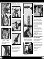
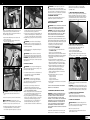
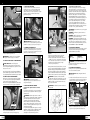
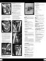

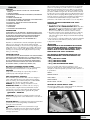
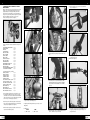


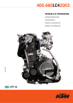


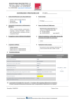
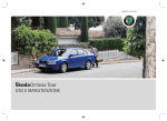


![Manuale [de]](http://vs1.manualzilla.com/store/data/006744650_1-ed92225d5e395f0fd2ab4bb1d4393f6a-150x150.png)