1
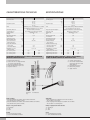
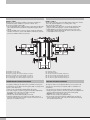
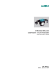
DAPK-2/DAPIK-2 USE AND MAINTENANCE DAPK-2/DAPIK-2 USO E MANUTENZIONE I GB CARATTERISTICHE TECNICHE DATI TECNICI Pressione d’esercizio Temperatura d’esercizio Fluido Smorzamento di finecorsa Controllo di finecorsa Angolo di rotazione Alesaggio Momento d’inerzia attorno all’asse centrale Coppia teorica a 6 bar Momento ribaltante MAX Carico assiale ammesso a trazione/compressione Energia critica ammissibile: con fermi elastici con deceleratori idraulici Ripetibilità (su 100 corse a condizioni costanti) Peso versione 2 posizioni Peso versione 3 posizioni Peso versione 4 posizioni DAPK-2 SPECIFICATIONS DAPIK-2 bar MPa psi °C °F 2÷7 0.2 ÷ 0.7 29 ÷ 101 -10 ÷ 80 14 ÷ 176 Aria filtrata 20 µm con o senza lubrificazione. Se si utilizza aria lubrificata la lubrificazione deve essere continua. Deceleratori idraulici o fermi elastici. Sensori induttivi, sensori nella versione magnetica. ° Regolabile da 0 ÷ 180 mm 32 kg.m2 0.030 Nm Nm N 3.8 15 240 / 460 Joule Joule 0.06 0.60 ≤ 0.01 - 0.02 ° kg kg kg 1.50 1.67 1.84 1.73 1.90 2.07 DIAGRAMMA PRESTAZIONI DAPK-2, DAPIK-2 CON DECELERATORI IDRAULICI E CON FERMI ELASTICI TECHNICAL DATA Operating pressure Temperature range Fluid End position stop shock-absorption End-position control Rotation angle Bore Moment of inertia around the central axis Theoretical torque at 6 bar Max overturning moment Allowable axial tensile stress/compression Allowable critical strain energy: with elastic mechanical stop with shock absorbers Repeatability (on 100 strokes at constant conditions) Weight of the 2-position version Weight of the 3-position version Weight of the 4-position version DAPK-2 bar MPa psi °C °F 2 to 7 0.2 to 0.7 29 to101 -10 to 80 14 to 176 Lubricated or unlubricated 20 μm filtered air. If lubricated air is used, lubrication must be continuous. Hydraulic shock-absorbers or elastic mechanical stop. Inductive sensors, magnetic sensors. ° Adjustable from 0 to 180 mm 32 kg.m2 0.030 Nm Nm N 3.8 15 240 / 460 Joule Joule 0.06 0.60 ≤ 0.01 - 0.02 ° kg kg kg 1.50 1.67 1.84 1.73 1.90 2.07 PERFORMANCE GRAPHS FOR DAPK-2, DAPIK-2 WITH HYDRALIC SHOCK-ABSORBERS AND ELASTIC MECHANICAL STOPS J = moment of inertia of mass n= max. number of double strokes per minute for the version with shock-absorbers p=pneumatic drive pressure t = traverse time per stroke φ= angle of rotation J = momento d’inerzia massa n= numero max. di corse doppie al minuto per versione con deceleratori p=pressione azionamento pneumatico t = tempo di traslazione per ogni corsa φ= angolo di rotazione with elastic mechanical stops 2 DAPIK-2 with shock-absorbers Ambito di validità: • Baricentro della massa in rotazione situato sull’asse di rotazione. Asse di rotazione in qualsiasi posizione. • Baricentro della massa in rotazione situato al di fuori dell’asse di rotazione. Asse di rotazione in posizione verticale. Applicability: • Centre of gravity of the rotating mass on the axis of rotation. Axis of rotation in any position. • Centre of gravity of the rotating mass outside the axis of rotation. Axis of rotation in a vertical position. Esempio con deceleratori idraulici: J = 0.010 kg.m2 φ= 150° p= 5 bar Example of hydraulic with shock-absorbers: J = 0.010 kg.m2 φ=150° p= 5 bar Risultati: nmax=50 corse doppie per minuto t = 0.34 s ammortizzatore standard Results: nmax=50 double strokes per minute t = 0.34 s standard shock absorber DIAGRAMMA DI PRESSIONE/COPPIA PRESSURE/TORQUE GRAPH 1) MH=p · 1.01 2) MB =p · 0.63 p =pressione d’azionamento. MH =momento di trattenuta; corrisponde a quello che può essere applicato dall’esterno sull’albero del pignone fermo, senza che l’albero stesso si muova. MB =momento di movimento; corrisponde a quello disponibile all’albero del pignone in movimento in seguito all’azionamento pneumatico. p =operation drive pressure. MH =holding moment, i.e. the one that can be applied from the outside on the shaft of a standstill pinion, with the shaft not rotating. MB =moment of movement, i.e. the one available for the shaft of the piston moving after pneumatic actuation. USO HOW TO USE POSIZIONE DI MONTAGGIO ASSEMBLY POSITION In linea di massima, le unità rotative possono essere utilizzate in qualsiasi posizione. Tuttavia occorre tener conto del fatto che, nei casi in cui l’asse di rotazione non è verticale e in cui il baricentro della massa in rotazione è eccentrico rispetto all’asse di rotazione, si possono verificare dei momenti di peso variabili. Questi possono agire sia nel senso di movimento, sia in senso inverso. Quindi è bene che il momento d’inerzia della massa ammissibile venga ridotto , e che il tempo “t” mostrato nella tabella a pag. 2 aumenti, e la velocità si riduca. In principle, the rotary drives can be used in any position. It is necessary, however, to take into consideration that, with the axis of rotation off- centred and the centre of rotation of the rotating mass eccentric to the axis of rotation, variable moments of weight may occur. They may act in the direction of movement or in the reverse direction. Reducing the moment of inertia of the admissible mass, increasing time “t” (as shown in the table on page 2) and reducing velocity is a good choice. 3 MONTAGGIO 4 ASSEMBLY Il montaggio delle unità rotative DAPK-2/DAPIK-2 può essere fatto come si vuole e su qualsiasi incastro a coda di rondine V-Lock a disposizione. I componenti V-Lock permettono di realizzare in fretta e facilmente ogni tipo di combinazione di montaggio. La correzione di posizione dell’unità rotativa (spostamento dell’asse) eventualmente necessaria determina quale fra le tre possibilità di fissaggio è la più adatta. Come mostrato nella figura seguente, è possibile, svitando le quattro viti di fissaggio, ruotare di 90° il piattello fisso del sistema V-Lock sul lato opposto del piattello rotante. The rotary drives DAPK-2/DAPIK-2 can be assembled as desired on any V-Lock dovetail fixing available. The V-Lock components can be used for quick-and-easy assembling in all types of configurations. The most suitable fixing solution out of the 3 available is determined according to the correction made to the rotary drive position (axis shift). As shown in the figure below, you can unscrew the four fixing screws and rotate the V-Lock system fixed plate by 90° on the opposite side of the rotary plate. Così come per il piattello precedente, è possibile, svitando le quattro viti di fissaggio, ruotare di 90° il piattello rotante del sistema V-Lock, come mostrato nella figura seguente. As with the previous plate, you can unscrew the four fixing screws and rotate the V-Lock system rotary plate by 90°, as shown in the figure below. ALIMENTAZIONE D’ARIA COMPRESSED AIR SUPPLY Si consiglia sempre il montaggio sugli ingressi aria (sia in rotazione oraria che antioraria) di un regolatore di flusso. Come indicato nel disegno sottostante, entrando dal filetto sul lato sinistro si comanda la ROTAZIONE IN SENSO ORARIO del piattello rotante mentre entrando dal lato destro si comanda la ROTAZIONE IN SENSO ANTIORARIO del piattello rotante. We always recommend mounting a flow regulator on compressed air inlets (both with clockwise and anticlockwise rotation). As shown in the figure below, with the inlet on the left-hand side, CLOCKWISE ROTATION of the rotary plate can be controlled; with the inlet on the right-hand side, ANTICLOCKWISE ROTATION of the rotary plate can be controlled. DAPK-2 DAPK-2 P1 = Rotazione in senso orario P2 = Rotazione in senso antiorario P1 = Clockwise rotation P2 = Anticlockwise rotation DAPIK-2 Gli ingressi e le uscite dell’aria sull’albero di rotazione standard sono quelli laterali (quando il piattello rotante è in posizione centrale - 90°). È comunque possibile ruotarle di 90°: •nel caso del piattello fisso è sufficiente svitare i tappi M5 posti nella parte alta e nella parte inferiore (riutilizzare i tappi tolti per tappare i filetti laterali); •nel caso del piattello rotante invece si devono svitare le quattro viti di fissaggio sull’albero di rotazione, ruotare di 90° il piattello e riutilizzare le stesse viti per bloccare il piattello nella nuova posizione. DAPIK-2 Air inlets and outlets on the standard rotating shaft are those at the sides (when the rotary plate is in the central position -90°). They can also be rotated by 90°: •with a fixed plate, you only need to unscrew the top and bottom M5 plugs (reuse the removed plugs to cover the side threaded ports); •with a rotary plate you need to unscrew the four fixing screws on the rotating shaft, rotate the plate by 90° and reuse the same screws to lock the plate in the new position. P1 - Rotazione in senso orario P2 - Rotazione in senso antiorario P3 - Ingresso passaggio aria a sinistra collegato con uscita P5 P4 - Ingresso passaggio aria a destra collegato con uscita P6 P5 - Uscita passaggio aria a sinistra collegato con ingresso P3 P6 - Uscita passaggio aria a destra collegato con ingresso P4 P1 - Clockwise rotation P2 - Anticlockwise rotation P3 - Air inlet on the left connected with outlet port P5 P4 - Air inlet on the right connected with outlet port P6 P5 - Air outlet on the left connected with inlet port P3 P6 - Air outlet on the right connected with inlet port P4 5 DAPIK-2 + WAK-2 Gli ingressi e le uscite dell’aria sull’albero di rotazione standard sono quelle laterali (quando il WAK-2 è in posizione centrale - 90°). È comunque possibile ruotarle di 90°: •nel caso del piattello fisso è sufficiente svitare i tappi M5 posti nella parte alta e nella parte inferiore (riutilizzare i tappi tolti per tappare i filetti laterali); •nel caso del WAK-2 invece si devono svitare le quattro viti di fissaggio sull’albero di rotazione, ruotare di 90° WAK-2 e riutilizzare le stesse viti per bloccare il WAK-2 nella nuova posizione. DAPIK-2 + WAK-2 The air inputs and outputs on the standard rotating shaft are those located on the sides (when the WAK-2 is in a central position - 90°). They can also be rotated by 90°: •with a fixed plate, you only need to unscrew the top and bottom M5 plugs (reuse the removed plugs to cover the side threaded ports); •with the WAK-2 you need to unscrew the four fixing screws on the rotating shaft, rotate the WAK-2 by 90° and reuse the same screws to lock the WKA-2 in the new position. P1 - Rotazione in senso orario P2 - Rotazione in senso antiorario P3 - Ingresso passaggio aria a sinistra collegato con uscita P5 P4 - Ingresso passaggio aria a destra collegato con uscita P6 P5 - Uscita passaggio aria a sinistra collegato con ingresso P3 P6 - Uscita passaggio aria a destra collegato con ingresso P4 P1 - Clockwise rotation P2 - Anticlockwise rotation P3 - Air inlet on the left connected with outlet port P5 P4 - Air inlet on the right connected with outlet port P6 P5 - Air outlet on the left connected with inlet port P3 P6 - Air outlet on the right connected with inlet port P4 REGOLAZIONE DELL’ANGOLO DI ROTAZIONE 6 ADJUSTING THE ANGLE OF ROTATION La regolazione dell’angolo di rotazione dev’essere fatta con la pressione inserita dal lato opposto alla boccola da regolare (120). Si consiglia di non superare i 2 bar di pressione. The angle of rotation must be adjusted with the pressure inserted on the side opposite to the bushing to be adjusted (120). It is advisable not to exceed 2 bar. •Svitare la vite a testa cilindrica (270a) del lato da regolare; •Per variare l’angolo di rotazione, togliere il deceleratore (220) del lato da regolare e far ruotare la boccola di finecorsa (120). Importante: 1 giro corrisponde a circa 8°. •Serrare la vite a testa cilindrica (270a) con 2.5 Nm; •Svitando completamente le boccole di finecorsa (120), si ottiene un angolo di rotazione massimo di 180°. In questo caso le due boccole di finecorsa sono in battuta sul corpo. •Unscrew the cheese-head screw (270a) from the side to be adjusted; •To adjust the angle of rotation, remove the shock absorber (220) from the side to be adjusted and rotate the end-of-stroke bushing (120). Important: 1 turn corresponds to about 8°. •Tighten the cheese-head screw (270a) at 2 Nm; •Unscrewing the end-of-stroke bushings (120) fully, gives an angle of rotation of maximum 180°. In this case, the two end-of-stroke bushings are in abutment with the body. REGOLAZIONE DEI DECELERATORI ADJUSTING THE SHOCK ABSORBERS La velocità di processo, il momento di inerzia di massa, la pressione di esercizio, come pure in certi casi, la posizione dell’asse di rotazione, influiscono sull’energia che devono assorbire i deceleratori. La regolazione ottimale di questi ultimi, vale a dire quella che dà il minor tempo di processo con i valori d’influsso dati, è ottenuta nel seguente modo: •Installare l’unità rotativa nella posizione voluta; •Allentare il controdado del deceleratore (400); •Svitare il deceleratore (220); •Immettere aria (Pressione max = 2 bar) fino ad arrivare in battuta sulla boccola di finecorsa del deceleratore da regolare; •Avvitare il deceleratore nella boccola di finecorsa (120) fino a fare coincidere la battuta del deceleratore con il piano delle boccole (120); •Svitare il deceleratore di circa mezzo giro per arretrarne la battuta rispetto a quella della boccola di finecorsa; •Serrare il controdado del deceleratore. ATTENZIONE: per evitare di danneggiare il deceleratore e preservarne la durata, è sempre consigliato: • che lo stelo del deceleratore sporga tra i 12 ed i 12,5 mm rispetto al piano di battuta della boccola nella quale viene avvitato (vedere disegno seguente) • monitorare frequentemente il corretto funzionamento del deceleratore ( non vi devono essere rimbalzi a fine corsa). Se il deceleratore dovesse essere danneggiato potrebbero verificarsi delle rotture della dentatura. Process speed, mass moment of inertia, operating pressure and, in some cases, the position of the axis of rotation have an impact on the energy to be absorbed by the shock absorbers. The optimal regulation of the shock absorbers, i.e. the one that gives the shortest process time with data input values, is obtained as follows: •Mount the rotary drive in the desired position; •Loosen the shock absorber lock nut (400); •Unscrew the shock absorber (220); •Supply air (max. pressure = 2 bar) until in abutment with the end-of-stroke bushing of the shock absorber to be adjusted; •Tighten the shock absorber in the end-of-stroke bushing (120) until the shock absorber abutment coincides with the plane of the bushings (120); •Unscrew the shock absorber by half a turn to move the abutment in a rear position with respect to the end-of-stroke bushing; •Tighten the shock absorber lock nut. IMPORTANT: in order to prevent damaging the shock absorber and ensure long life, it is always advisable that: • the shock absorber rod protrudes 12-12.5 mm from the abutment surface of the bushing in which it is screwed on (see drawing below); • the operation of the shock absorber is frequently monitored. (no bounces at the end of the stroke). If the shock absorber gets dama ged, this could cause the teeth to break off. ATTENZIONE: gli MRF (440) non sono compresi nella fornitura IMPORTANT: The MRFs (440) are not included in the supply. 7 REGOLAZIONE E ALLACCIAMENTO DEI SENSORI INDUTTIVI ADJUSTING AND CONNECTING INDUCTIVE SENSORS Inductive sensors can only be adjusted when the angle of rotation has been set and can no longer be modified. Inductive sensors must have a 1-2 mm switching interval (Sn), be designed for flush installation and have a seat diameter of 6.5 mm. I sensori induttivi possono essere regolati soltanto quando è stato definito l’angolo di rotazione che non viene più modificato. I sensori induttivi devono avere un intervallo di commutazione (Sn) di 1 - 2 mm, essere previsti per l’installazione a filo e avere un diametro di alloggiamento di 6.5 mm. Adjustment procedure: •Rotate the plate until it reaches the set end-of-stroke position; •Fit the inductive sensor in the clamping bushing (150) and fix both of them in the hole in the body (10), in such a way that the front surface of the bushing (150) positions at a distance of around 0.3 mm from the actuator (70). If the inductive sensor is connected electrically, the LED light comes on; •Secure the bushing (150) and the inductive proximity switch in position by slightly tightening the grub screw (300). Procedimento di regolazione: •Ruotare il piattello fino a raggiungere la posizione di finecorsa prestabilita; •Innestare il sensore induttivo nella boccola di bloccaggio (150) e sistemare entrambi nel foro del corpo (10), in modo che la superficie frontale della boccola (150) si situi ad una distanza di circa 0.3 mm dall’attuatore (70). Se il sensore induttivo è allacciato elettricamente, a questo punto si accende il LED; •Bloccare la boccola (150) e l’interruttore di prossimità induttivo serrando leggermente il grano (300). ALLACCIAMENTO ELETTRICO DEI SENSORI INDUTTIVI ELECTRICAL CONNECTION OF INDUCTIVE SENSORS DC DC brown NPN ATTENZIONE: gli MRF (440) non sono compresi nella fornitura blue Z brown + A PNP 0V + black blue Z A 0V IMPORTANT: The MRFs (440) are not included in the supply. MANUTENZIONE 8 black MAINTENANCE Controllo dei deceleratori. I deceleratori montati sulla serie DAPK-2/DAPIK-2 sono della più alta qualità ma malgrado ciò, può succedere che qualche ammortizzatore si guasti. Consigliamo perciò di badare che, durante il funzionamento, le masse rotanti non impattino contro le loro batture di finecorsa. Se questo dovesse comunque succedere, è indispensabile procedere alla regolazione del deceleratore in questione, conformemente alle istruzioni della sezione “Regolazione dei deceleratori”. Se non è possibile ottenere un risultato soddisfacente, occorre sostituire l’ammortizzatore. Checking the shock absorbers. The shock absorbers mounted on the DAPK-2/DAPIK-2 series feature the highest quality level, it can happen, however, that a shock absorber fails. This is why we recommend to make sure that, during operation, the rotating masses do not impact against their end-of-stroke abutments. Should this occur, it is essential to adjust the sock-absorber involved in accordance with the instructions given in section entitled “Adjusting the shock absorbers”. If a satisfactory result cannot be achieved, the shock absorber must be replaced. Nota: gli ammortizzatori difettosi riducono notevolmente la durata utile dell’unità rotativa. Inoltre non è più possibile garantire la precisione e la riproducibilità delle posizioni di finecorsa. Note: Faulty shock absorbers considerably shorten the useful life of the rotary drive. It is no longer possible to guarantee precision and repeatability of end-of-stroke positions. Se dovesse eventualmente sopraggiungerne la necessità consigliamo di eseguire i seguenti lavori di manutenzione: •Pulizia dell’apparecchio, specialmente della meccanica di guida; •Controllo ed eventuale sostituzione delle guarnizioni; •Lubrificazione, specialmente della meccanica di guida, con olio lubrificante cod. 9910490. If this happens, it is advisable to perform the following maintenance work: •Cleaning the apparatus, especially the drive mechanical parts; •Checking the gaskets and replacing them, if necessary; •Lubricating the shock absorbers, especially the drive mechanical parts, using lubricating oil code 9910490. www.metalwork.eu ZRCVK0002 - IM00_10/2014