1
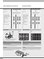
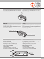
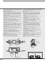
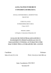
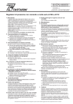
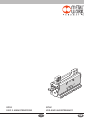
GPLK
USE AND MAINTENANCE
GPLK
USO E MANUTENZIONE
I
GB
CARATTERISTICHE TECNICHE
GPLK
1-30
DATI TECNICI
Pressione d’esercizio
Temperatura d’esercizio
Fluido
bar
MPa
psi
°C
Forza di serraggio di una singola
N
griffa a 6,3 bar a 20 mm dal piano
superiore, in apertura e chiusura
Corsa di una singola griffa, regolabile
mm
Corsa totale massima
mm
Tempo minimo apertura/chiusura
misurato a corsa massima:
a 3 bar
s
a 6 bar
s
Ripetibilità (su 100 corse a condizioni
mm
costanti)
Momento d’inerzia attorno
kg.cm2
all’asse y
Peso
kg
Carichi massimi statici ammissibili
Ft
N
Fa
N
Mx
Nm
My
Nm
Mz
Nm
GPLK
1-40
GPLK
2-45
SPECIFICATIONS
GPLK
2-60
GPLK
2-75
2÷8
0.2 ÷ 0.8
29 ÷ 116
-10 ÷ 80
Aria filtrata 20 µm con o senza lubrificazione.
Se si utilizza aria lubrificata la lubrificazione deve
essere continua
42
116
1 ÷ 15
30
6 ÷ 20
40
0.18
0.10
0.22
0.12
5.5 ÷ 22.5 13 ÷ 30 20 ÷ 37.5
45
60
75
0.44
0.28
< 0.03
0.60
0.32
< 0.04
0.76
0.36
3.5
4.4
16.4
21.5
29.1
0.44
0.46
1.04
1.12
1.26
7.5
70
9
4
7
15
120
37
23
22
FORZE E MOMENTI
GPLK
1-30
TECHNICAL DATA
Operating pressure
bar
MPa
psi
°C
Temperature range
Fluid
Clamping force of a single jaw
at 6.3 bar, 20 mm from the upper
surface, on opening and closing
Single jaw stroke, adjustable
Maximum overall stroke
Minimum opening/closing time
measured at maximum stroke:
at 3 bar
at 6 bar
Repeatability ((on 100 strokes at
constant conditions)
Moment of inertia around
the y axis
Weight
Max. admissible static loads
Ft
Fa
Mx
My
Mz
GPLK
1-40
GPLK
2-45
GPLK
2-60
GPLK
2-75
2 to 8
0.2 to 0.8
29 to 116
-10 to 80
20 μm filtered air, lubricated or unlubricated.
If lubricated air is used, lubrication must
be continuous
42
116
N
mm
mm
1 to 15
30
s
s
mm
0.18
0.10
kg.cm2
kg
6 to 20 5.5 to 22.5 13 to 30 20 to 37.5
40
45
60
75
0.22
0.12
0.44
0.28
0.60
0.32
< 0.04
0.76
0.36
3.5
4.4
16.4
21.5
29.1
0.44
0.46
1.04
1.12
1.26
< 0.03
N
N
Nm
Nm
Nm
7.5
70
9
4
7
15
120
37
23
22
FORCES AND MOMENTS
GPLK-2
GPLK-1
F [N]
160
8 bar
140
120
6.3 bar
100
80
4 bar
60
40
F
Ft
Fa
Mx, My, Mz
forza di serraggio / clamping force
forza trasversale statica massima / maximum static traverse force
forza assiale statica massima / maximum static axial force
momenti statici massimi / maximum static moments
0
USO
HOW TO USE
POSIZIONE DI MONTAGGIO
ASSEMBLY POSITION
La posizione di montaggio delle pinze GPLK è a piacere.
MONTAGGIO
Le pinze GPLK vengono fissate al loro contenitore in modo rapido e
semplice con il sistema di fissaggio V-Lock.
2
20 2 bar
0
20
40
60
80 100 120 140 160 180 200 220
L [mm]
The GPLK grippers can be mounted in any position.
ASSEMBLY
It is quick and easy to secure the GPLK grippers to their container using the
V-Lock system.
Se non si utilizzano componenti V-Lock, è possibile fissare le pinze GPLK
direttamente con viti e spine.
INGRESSI ARIA
If V-Lock components are not used, the GPLK grippers can be secured
directly with screws and pins.
AIR INLETS
Si consiglia sempre il montaggio sugli ingressi aria (sia in apertura che in
chiusura) di un regolatore di flusso.
Come indicato nel disegno sottostante, entrando dal filetto sul lato sinistro
si comanda la CHIUSURA della pinza mentre entrando dal lato destro si
comanda l’APERTURA della pinza.
It is advisable to mount a flow regulator on the air inlets (on opening and
closing).
As shown in the drawing below, when entering from the thread on the left
side, the gripper are CLOSE, conversely when entering from the thread on
the right side, the gripper OPEN UP.
CHIUSURA pinza / Gripper CLOSING
APERTURA pinza / Gripper OPENING
REGOLAZIONE DEGLI ARRESTI DI FINECORSA
Con le viti 250 e i dadi 260 si fissano le due posizioni estreme “Pinza
aperta” (A) e “Pinza chiusa” (B).
Procedura di regolazione “Pinza aperta”:
• Svitare dado 260 (A);
• Aprire la pinza in posizione non soggetta a pressione;
• Impostare la posizione di arresto con la vite 250 (A);
• Assicurare la posizione di arresto fissando il dado 260 (A).
Procedura di regolazione “Pinza chiusa”:
• Svitare dado 260 (B);
• Chiudere la pinza in posizione non soggetta a pressione;
• Impostare la posizione di arresto con la vite 250 (B);
• Assicurare la posizione di arresto fissando il dado 260 (B).
ADJUSTING THE END-OF-STROKE STOPS
The screws 250 and nuts 260 can be used to secure the two “Grippers
open” (A) and “Grippers closed” (B) end positions.
“Grippers open” adjusting procedure:
• Unscrew the nut 260 (A);
• Open the grippers in a position not subject to pressure;
• Set the stop position using the screw 250 (A);
• Secure the stop position by tightening the nut 260 (A).
“Grippers closed” adjusting procedure:
• Unscrew the nut 260 (B);
• Close the grippers in a position not subject to pressure;
• Set the stop position using the screw 250 (B);
• Secure the stop position by tightening the nut 260 (B).
3
REGOLAZIONE E ALLACCIAMENTO DEI SENSORI INDUTTIVI
ADJUSTING AND CONNECTING INDUCTIVE SENSORS
Pinza aperta (A) e pinza chiusa (B).
I sensori induttivi impiegati devono avere un intervallo di commutazione Sn di 2
mm, e avere un diametro del corpo di 6,5 mm.
Procedura di regolazione della pinza con “afferraggio del pezzo dall’esterno”:
•Chiudere la pinza (senza pressione) finchè le dita di presa toccano il pezzo;
•Regolare l’arresto B (pinza chiusa) in modo che, quando le dita di presa sono
in contatto con il pezzo, vi sia una distanza di circa 0,5 mm tra la vite di
regolazione e la griffa.
•Inserire il sensore induttivo B nella piastra (130) fino a battuta. Se provvisto di
LED, quando il sensore è collegato elettricamente, il LED si accende;
•Tirare indietro il sensore induttivo, finchè fra esso e la griffa vi è una distanza
di circa 1 mm;
•Bloccare il sensore induttivo serrando la vite 360 (B);
•Inserire il sensore induttivo A nella piastra (130) fino a battuta. Se provvisto di
LED, quando il sensore è collegato elettricamente, il LED si accende;
•Aprire la pinza fino alla battuta impostata A (senza pressione);
•Tirare indietro il sensore induttivo, finchè fra esso e la griffa vi è una distanza
di circa 0,5 mm;
•Bloccare il sensore induttivo serrando la vite 360 (A).
Procedura di regolazione della pinza con “afferraggio del pezzo dall’interno”:
•Aprire la pinza (senza pressione) finchè le dita di presa toccano il pezzo;
•Regolare l’arresto A (pinza aperta) in modo che, quando le dita di presa sono
in contatto con il pezzo, vi sia una distanza di circa 0,5 mm tra la vite di
regolazione e la griffa;
•Inserire il sensore induttivo A nella piastra (130) fino a battuta. Se provvisto di
LED, quando il sensore è allacciato elettricamente, il LED si accende;
•Tirare indietro il senosre induttivo, finchè fra esso e la griffa vi è una distanza
di circa 1 mm;
•Bloccare il il sensore induttivo serrando la vite 360 (A);
•Inserire il sensore induttivo B nella piastra (130) fino a battuta. Se provvisto di
LED, quando il sensore è collegato elettricamente, il LED si accende;
•Chiudere la pinza fino alla battuta impostata B(senza pressione);
•Tirare indietro il sensore induttivo, finchè fra esso e la griffa vi è una distanza
di circa 0.5 mm;
•Bloccare il sensore induttivo serrando la vite 360 (B).
Grippers open (A) and grippers closed (B).
The inductive sensors used must have a 2 mm switching interval and a body
diameter of 6.5 mm.
Grippers setting procedure by “clamping the workpiece from the outside”:
•Close the grippers (without forcing) until the jaws touch the workpiece;
•Adjust stop B (grippers closed) in such a way that when the jaws touch the
workpiece the clearance between the setting screw and the jaw is about
0.5 mm.
•Insert the inductive sensor B in the plate (130) until it goes.
The LED, if provided, comes on when the sensor is powered on;
•Pull back the inductive sensor until a clearance of around 1 mm is obtained
between it and the jaw;
•Lock the inductive sensor in position by tightening the screw 360 (B);
•Insert the inductive sensor A in the plate (130) until it goes. The LED, if
provided, comes on when the sensor is powered on;
•Open the grippers up to the set stop A (without forcing);
•Pull back the inductive sensor until a clearance of around 0.5 mm is obtained
between it and the jaw;
•Lock the inductive sensor in position by tightening the screw 360 (A).
Grippers setting procedure by “clamping the workpiece from the inside”:
•Open the grippers (without forcing) until the jaws touch the workpiece;
•Adjust stop A (gripper open) in such a way that when the jaws touch the
workpiece the clearance between the setting screw and the jaw is about
0.5 mm.
•Insert the inductive sensor A in the plate (130) until it goes. The LED, if
provided, comes on when the sensor is powered on;
•Pull back the inductive sensor until a clearance of around 1 mm is obtained
between it and the jaw;
•Lock the inductive sensor in position by tightening the screw 360 (A);
•Insert the inductive sensor B in the plate (130) until it goes. The LED, if provided,
comes on when the sensor is powered on;
•Close the grippers up to the set stop B (without forcing);
•Pull back the inductive sensor until a clearance of around 0.5 mm is obtained
between it and the jaw;
•Lock the inductive sensor in position by tightening the screw 360 (B).
ATTENZIONE: Nelle due posizioni estreme formate dagli arresti A e B le griffe
non devono toccare gli interruttori di prossimità 1 (A) o 2 (B).
IMPORTANT! In the two end positions identified by stops A and B, the jaws must
not touch the proximity switches 1 (A) or 2 (B).
La figura sotto mostra la versione con afferraggio del pezzo dall’esterno.
The figure below shows the version with clamping of the workpiece from the
outside.
~1
130
370 (A)
B
A
B
A
A
B
~0,5
360 (A)
Pezzo/Piece
370 (B)
360 (B)
ALLACCIAMENTO ELETTRICO DEI SENSORI INDUTTIVI
ELECTRICAL CONNECTION OF INDUCTIVE SENSORS
DC
DC
brown
NPN
Pezzo/Piece
4
www.metalwork.eu
black
blue
Z
brown
+
A
0V
PNP
+
black
blue
Z
A
0V
ZPCVK0001 - IM00_06/2014