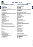
1
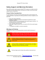
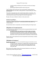
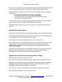
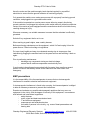
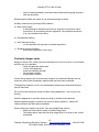
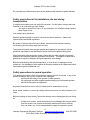
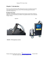
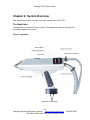
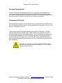
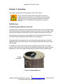
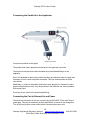
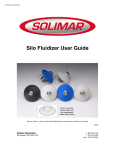
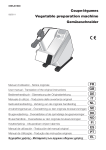
User’s Guide Resodyn PTS-5 User’s Guide Table of Contents Safety, Support and Warranty Information....................................................................... 4 General Safety Considerations .................................................................................... 4 Warnings and Cautions ............................................................................................... 4 General remarks .......................................................................................................... 5 Utilization for intended purpose only ............................................................................ 5 Ambient conditions ...................................................................................................... 6 Obligations of Licensee/operator ................................................................................. 6 Obligations of personnel .............................................................................................. 6 Protection for yourself and other persons .................................................................... 7 Hazards from noxious gases and vapors ..................................................................... 7 Hazards from heat source............................................................................................ 8 Hazards from electric mains and machine voltage ....................................................... 8 EMC precautions ......................................................................................................... 9 Particular danger spots .............................................................................................. 10 Safety precautions at the installation site and during transportation ........................... 11 Safety precautions in normal operation ...................................................................... 11 Preventive and corrective maintenance ..................................................................... 12 Safety inspection ....................................................................................................... 12 Copyright ................................................................................................................... 12 Product Safety Marking Symbols ............................................................................... 13 Important Safety Notes .............................................................................................. 13 Troubleshooting and Warranty Service ...................................................................... 14 Chapter 1: Introduction .................................................................................................. 15 Product Overview ...................................................................................................... 15 The PTS-5 is comprised of: .................................................................................... 16 Applicator Features: ............................................................................................... 16 Cart Features: ........................................................................................................ 16 Installation ................................................................................................................. 16 Specifications ............................................................................................................ 17 Chapter 2: System Overview ......................................................................................... 18 The Applicator ........................................................................................................... 18 The Cart .................................................................................................................... 20 Storage Compartment ............................................................................................... 21 Compressed Air Input ................................................................................................ 21 Powder Hopper .......................................................................................................... 22 Control Panel - User Interface ................................................................................... 23 Control Box - Back Panel ........................................................................................... 24 Chapter 3: Operation ..................................................................................................... 25 Initial Set-up............................................................................................................... 25 Connecting the Umbilical to the Cart. ..................................................................... 25 Connecting the Umbilical to the Applicator ............................................................. 26 Connecting the Cart to External Air and Power ...................................................... 26 Prepare the Powder Hopper ................................................................................... 27 2 Resodyn Engineered Polymeric Systems www.resodyncoatings.com 130 N. Main Street, Suite 620, Butte, Montana 59701 406-497-5288 Resodyn PTS-5 User’s Guide Operating the Control Cart ..................................................................................... 27 Turning on the Powder Feed .................................................................................. 28 General Starting Parameters ..................................................................................... 29 Application General Guidelines .............................................................................. 29 Spraying a Polymer Thermal Spray Coating with the PTS-5................................... 30 Parameter Set-up checklist .................................................................................... 31 Applying a Coating ................................................................................................. 32 Chapter 5: Care and Maintenance................................................................................. 34 Care & cleaning ......................................................................................................... 34 Chapter 6: Troubleshooting ........................................................................................... 36 3 Resodyn Engineered Polymeric Systems www.resodyncoatings.com 130 N. Main Street, Suite 620, Butte, Montana 59701 406-497-5288 Resodyn PTS-5 User’s Guide Safety, Support and Warranty Information Every effort has been made to ensure that the PTS-5 is easy to use, reliable, and safe. This section will outline general safety considerations and define caution and warning symbols used in this document. General Safety Considerations For safe operation, the PTS-5 should be operated only within the limits outlined in the system specifications. Specifically the following classification defines acceptable use for the PTS-5 Indoor and outdoor applications Operator must observe all national and international regulations for proper workspace ventilation. Ordinary Protection: NOT protected against the harmful ingress of moisture. Do not allow to get wet from rain or other sources. Class I Equipment (grounded type) Main supply voltage fluctuations are not to exceed ±10% of the nominal supply voltage. This equipment is suitable for continuous operation Warnings and Cautions Throughout the manual, the following symbols are used to identify warnings and cautions: “Danger!” indicates an imminently hazardous situation which, if not avoided, will result in death or serious injury. This signal word is to be limited to the most extreme situations. This signal word is not used for property damage hazards unless personal injury risk appropriate to this level is also involved. “Warning!” indicates a potentially hazardous situation which, if not avoided, could result in death or serious injury. This signal work is not used for property damage hazards unless personal injury risk appropriate to this level is also involved. “Caution!” indicates a potentially hazardous situation which, if not avoided may result in minor or moderate injury. It may also be used to alert against unsafe practices that may cause property damage. The high voltage symbol indicates the possibility of electrical shock 4 Resodyn Engineered Polymeric Systems www.resodyncoatings.com 130 N. Main Street, Suite 620, Butte, Montana 59701 406-497-5288 Resodyn PTS-5 User’s Guide Hot surface – touching this surface could result in burns or discomfort General remarks This equipment has been made in accordance with the state-of-the-art and all recognized safety rules. Nevertheless, incorrect operation or misuse may still lead to danger for: - the life and well-being of the operator or of third parties, - the equipment and other tangible assets belonging to the owner/operator, - efficient working with the equipment. All persons involved in any way with starting up, operating, servicing and maintaining the equipment must: - be suitably qualified - know about Polymer Thermal Spray equipment and processes - read and follow exactly the instructions given in this manual. The instruction manual must be kept at the machine location at all times. In addition to the instruction manual, copies of both the generally applicable and the local accident prevention and environmental protection rules must be kept on hand, and of course observed in practice. All the safety instructions and danger warnings on the machine itself: - must be kept in a legible condition - must not be damaged - must not be removed - must not be covered, pasted or painted over Any malfunctions which might impair machine safety must be repaired immediately and prior to next use. Have a suitable and approved fire extinguisher on site. It’s your safety that’s at stake! Utilization for intended purpose only The PTS system may only be used for the intended purpose of polymer coating creation using Resodyn Engineered Polymeric Systems (Resodyn) approved coating materials. Utilization for any other purpose, or in any other manner, or with non-Resodyn coating materials, shall be deemed to be not in accordance with the intended purpose. The manufacturer shall not be liable for any damage resulting from such improper use. Utilization in accordance with the intended purpose also comprises: - complete reading and following of all the instructions given in this manual 5 Resodyn Engineered Polymeric Systems www.resodyncoatings.com 130 N. Main Street, Suite 620, Butte, Montana 59701 406-497-5288 Resodyn PTS-5 User’s Guide - complete reading and following of all the safety instructions and danger warnings performing all stipulated inspection and servicing work. The PTS system and its heat source must never be used for anything other than preheating substrates to be coated, coating application, and post-heating the coating after deposition. The machine is designed to be used in industrial and workshop environments. The manufacturer shall not be liable for any damage resulting from use of the machine in residential premises beyond Resodyn approved commercial applications. Resodyn will accept no liability for defective or faulty work results. Ambient conditions Operation or storage of the PTS system outside the stipulated range is deemed to be not in accordance with the intended use. The manufacturer shall not be liable for any resulting damage. See Specification Section for stipulated environmental operating and storage ranges. Obligations of Licensee/operator The licensee/operator undertakes to ensure that the only persons allowed to work with the machine are persons who: - are familiar with the basic regulations on workplace safety and accident prevention and who have been instructed in how to operate the machine - have read and understood the sections on safety rules and the warnings contained in this manual, and have confirmed as much with their signatures - be trained in such a way that meets with the requirements of the work results Regular checks must be performed to ensure that personnel are still working in a safetyconscious manner. Obligations of personnel Before starting work, all persons to be entrusted with carrying out work with (or on) the machine shall undertake: - to observe the basic regulations on workplace safety and accident prevention - to ready the sections on safety rules and the warnings contained in this manual, and to sign to confirm that they have understood these and will comply with them Before leaving the workplace, personnel must ensure that there is no risk of injury or damage being caused during their absence. 6 Resodyn Engineered Polymeric Systems www.resodyncoatings.com 130 N. Main Street, Suite 620, Butte, Montana 59701 406-497-5288 Resodyn PTS-5 User’s Guide Protection for yourself and other persons When polymer thermal spraying, you are exposed to many different hazards, such as: - heat source - flying hot polymer particles - exposed hot equipment and substrate surfaces - compressed air - flying dust debris particles - increased exposure to noise - electrical hazards Anyone working on the vicinity of the polymer thermal spray application process must wear suitable protective clothing with the following characteristics: - flame-retardant - isolating and dry - must cover whole body, be undamaged and in good condition Protective clothing also includes: - protecting your eyes and face from heat, and flying debris with an appropriate safety shield or safety glasses - wearing full cover footwear that will also insulate from heat and molten plastic - Protecting your hands by wearing appropriate heat-proof gloves To lessen your exposure to noise and to protect your hearing against injury, wear ear protection. Keep other people – especially children – well away from the equipment and the polymer thermal spray application while in progress. If there are still any other persons nearby during operation, you must: - draw their attention to all the dangers (risk of being burned by hot gasses from applicator or from touching applicator, flying dust debris, flying hot polymer particles, high noise emission levels, possible electrical hazards - provide them with suitable protective equipment and/or - erect suitable protective partitions or curtains. Hazards from noxious gases and vapors Polymer fumes emitted when burned may contain gases and vapors that are harmful to health. Do not inhale fumes or noxious gases. Extract all fumes and gases away from the workplace. Ensure a sufficient supply of fresh air. Where insufficient ventilation is available, use a properly rated respirator mask, or mask with an independent fresh air supply. 7 Resodyn Engineered Polymeric Systems www.resodyncoatings.com 130 N. Main Street, Suite 620, Butte, Montana 59701 406-497-5288 Resodyn PTS-5 User’s Guide If you are not sure whether your fume-extraction system is sufficiently powerful, compare the measured pollutant emission values with the permitted threshold limit values. The harmfulness of the polymer thermal spray fumes will depend on e.g. the following components: - the substrates onto which the coating is being applied - the chemical composition of the coating being applied - any other coatings in the immediate vicinity of the coating process - all cleaning and degreasing agents For this reason, refer to the relevant Materials Safety Data Sheets and the information given by the manufacturer regarding the components listed above. Keep all flammable vapors (e.g. solvents, fuel gases) well away from the application process. Hazards from heat source Never perform polymer thermal spray application anywhere near combustible materials. Combustible materials must be at least 35 feet (11 meters) away from the heat source, or else must be covered over with approved coverings. Take suitable measures to ensure that there is no risk of injury or fire Do not perform polymer thermal spray applications in locations that are at risk from fire and/or explosion, or in enclosed tanks, barrels or pipes, unless these have been prepared for the application process in accordance with the relevant national and international standards. Polymer thermal spray application must NEVER be performed on containers that have had gases, fuels, mineral oils etc. stored in them. Even small traces of these substances left in the containers are a major explosion hazard. Hazards from electric mains and machine voltage Electric shock can be fatal or hazardous to life. Do not touch any exposed electrical conductors, either inside or outside the machine. All cables and other leads must be firmly attached, undamaged, properly insulated and adequately dimensioned. Immediately replace any loose connections, scorched, damaged or under dimensioned cables or other leads. Do not loop any cables or other leads around your body or any part of your body. Never expose the applicator to liquid in order to cool it. 8 Resodyn Engineered Polymeric Systems www.resodyncoatings.com 130 N. Main Street, Suite 620, Butte, Montana 59701 406-497-5288 Resodyn PTS-5 User’s Guide Have the mains and the machine supply leads checked regularly by a qualified electrician to ensure that the ground conductor is functioning properly. Only operate the machine on a mains power source with a properly functioning ground conductor, and plugged into a grounded outlet socket. If the machine is operated on a mains power source without a properly functioning ground conductor, and plugged into a power outlet socket without a protective-conductor contact, this counts as gross negligence and the manufacturer shall not be liable for any resulting damage or injury. Wherever necessary, use suitable measures to ensure that the substrate is sufficiently grounded. Switch off any equipment that is not in use. When working at great heights, wear a safety harness. Before performing maintenance on the equipment, switch if off and unplug it from the power source. Follow lock out/tag out regulations. Put up a clearly legible and easy-to-understand warning sign to stop anyone form inadvertently plugging the machine back into the power source and switching it back on again. Prior to performing maintenance: - discharge any components storing an electrical charge - ensure that all machine components are electrically inert. If work needs to be performed on any electrically live parts, there must be a second person on hand to immediately switch off the machine at the main switch in an emergency. EMC precautions It is the responsibility of the licensee/operator to ensure that no electromagnetic interference is caused to electrical and electronic equipment. If electromagnetic interference is found to be occurring, the licensee/operator is obliged to take all necessary measures to prevent this interference. Examine and evaluate any possible electromagnetic problems that may occur on equipment in the vicinity, and the degree of immunity of this equipment, in accordance with national and international regulations: - safety features - mains, signal and data-transmission leads - IT and telecoms equipment - measurement and calibration devices - the health of persons in the vicinity, e.g. users of heart pacemakers and hearing aids 9 Resodyn Engineered Polymeric Systems www.resodyncoatings.com 130 N. Main Street, Suite 620, Butte, Montana 59701 406-497-5288 Resodyn PTS-5 User’s Guide - users of heart pacemakers must take medical advice before going anywhere near the equipment Electromagnetic fields may cause as yet unknown damage to health. Ancillary measures for preventing EMC problems: a) Main power supply: - If electromagnetic interference still occurs, despite the fact that the mains connection is in accordance with the regulations, take additional measures (e.g. use a suitable mains filter). b) Equipotential bonding c) Work piece grounding: - run a connection to the ground via suitable capacitors c) Shielding, where necessary: - Shield other equipment in the vicinity Particular danger spots Keep your hands, hair, clothing and tools well away from the hot air path, or hot surfaces while the gun is in operation: - inside the applicator heater area - in front of the applicator - metal heat shielding shrouds - hot substrate surfaces - molten plastic surfaces Covers and guards are not to be removed except by an authorized Resodyn service technician, and will be immediately replaced after work has been completed. The applicator assembly is not to be disassembled except by an authorized Resodyn service technician. Do not touch the work piece during and after coating application – risk of injury from burning. Allow the applicator to cool down before touching or performing maintenance. Special regulations apply to rooms at risk from fire and/or explosion. Observe all relevant national and international standards. When hoisting the machines by crane, only use suitable lifting devices: - Attach the chains and/or ropes to suitable lifting points - The chains and/or ropes must be at an angle which is as close to the vertical as possible. 10 Resodyn Engineered Polymeric Systems www.resodyncoatings.com 130 N. Main Street, Suite 620, Butte, Montana 59701 406-497-5288 Resodyn PTS-5 User’s Guide Do not attach any chains and/or ropes to the stainless steel handles or plastic handles. Safety precautions at the installation site and during transportation A machine that topples over can easily kill someone! For this reason, always place the machine on an even and level floor surface. -An angle of inclination of up to 10° is permissible, but will affect powder feeding when hopper is low. Lock casters when stationary. Special regulations apply to rooms at risk from fire and/or explosion. Observe all national and international regulations. By means of internal instructions and checks, ensure that the workplace and the surrounding area are always kept clean and tidy. The equipment system must only be installed and operated in accordance with the protection type stated in the specification and/or listed on the specifications plate. When transporting the equipment system, ensure that the valid national and regional guidelines and accident protection regulation are followed. This applies in particular to guidelines in respect of dangers during transportation and carriage. Before commissioning and after transportation, a visual check for damage must be performed. Any damage must be repaired by Resodyn-trained service personnel before commissioning and/or additional use. Safety precautions in normal operation Only operate the machine if all of its protective features are fully functional. If any of the protective features are not fully functional, this endangers: - the life and well-being of the operator or other persons - the equipment and other tangible assets belonging to the licensee/operator - efficient working with the equipment Any safety features that are not fully functional must be repaired prior to use. Never evade, disable, or remove any safety features and never put safety features out of order. Before switching on the machine, ensure that nobody can be endangered by your doing so: - At least once a week, check the machine for any damage that may be visible from the outside, and check that the safety features all function correctly. Only use clean, dry, oil free compressed air supply to equipment system 11 Resodyn Engineered Polymeric Systems www.resodyncoatings.com 130 N. Main Street, Suite 620, Butte, Montana 59701 406-497-5288 Resodyn PTS-5 User’s Guide - Compressed air supply contaminated with excessive oil could cause an explosive flame during operation of the applicator. Oil in the air supply will cause damage to the equipment system. Preventive and corrective maintenance Use only OEM parts. If parts are sourced from other suppliers there is no certainty that these parts will have been designed and manufactured to cope with the stresses and safety requirements that will be made on them. Use only original spares listed in this guide. Do not make any alterations, installations or modifications to the machine without prior express written permission form the manufacturer. Replace immediately any components that are not in perfect condition. When ordering replacement parts include description and part number from the spares list with the order. Pease also quote the serial number of your equipment system. Safety inspection The licensee/operator is obliged to have a safety inspection performed on the machine at least once every 12 months. Resodyn also recommends the same 12-month interval for regular calibration of operating systems. Calibration should be performed any time a change in operation performance is detected by the operator. A safety inspection, by a Resodyn trained technician is prescribed: - after any alterations - after any modifications or installations of additional components - following repairs, care and maintenance - at least every twelve months Observe the relevant national and international standards and directives in connection with the safety inspection. Copyright Copyright to this instruction manual remains the property of Resodyn Engineered Polymeric Systems. The text and illustrations are all technically correct at the time of printing. The right to effect modifications is reserved. The contents of the instruction manual shall not provide the basis for any claims whatever on the part of the licensee. 12 Resodyn Engineered Polymeric Systems www.resodyncoatings.com 130 N. Main Street, Suite 620, Butte, Montana 59701 406-497-5288 Resodyn PTS-5 User’s Guide Product Safety Marking Symbols The following safety marking symbols are used on the product to identify potential dangerous hazard which could result in injury: Caution, Refer to Manual Caution, Risk of Electrical Shock Flammable Earth Ground Protective Conductor Terminal Important Safety Notes Operators must read this user guide thoroughly prior to use. Failure to do so may cause serious bodily harm and equipment damage. Do not use this equipment in areas where there is a risk of fire or explosion. Do not point the applicator in a direction that may ignite clothing such as nylon or similar materials. Keep flammable debris away from work area to prevent fires. Always use in ventilated area. Do not store applicator in cart until completely cooled. Continue air flow through applicator until all applicator surfaces reach ambient temperature. 13 Resodyn Engineered Polymeric Systems www.resodyncoatings.com 130 N. Main Street, Suite 620, Butte, Montana 59701 406-497-5288 Resodyn PTS-5 User’s Guide Troubleshooting and Warranty Service The PTS-5 system should only be operated when it is in good working condition. If the system shows any signs of visible damage or fails to operate as outlined in this manual, the system should not be operated. For operational errors and troubleshooting, see Chapter 6. If necessary, contact your Resodyn customer service representative for additional technical support. Resodyn Customer Service: Customer Service Resodyn, Engineered Polymeric Systems Phone: (406) 497-5288 e-mail: [email protected] Warranty service will be provided by Resodyn under the terms of your licensing agreement. User will be required to perform standard and routine maintenance to ensure the equipment is in proper working order at all times. Damage to the PTS-5 caused by improper maintenance, improper handling and care, or resulting from improper use in not covered under the warranty terms of the license agreement. The cost for repairs necessary due to user caused damage will be the responsibility of the licensee. 14 Resodyn Engineered Polymeric Systems www.resodyncoatings.com 130 N. Main Street, Suite 620, Butte, Montana 59701 406-497-5288 Resodyn PTS-5 User’s Guide Chapter 1: Introduction This user’s guide describes the PTS-5 thermal spray system and explains its operation. This chapter provides an overview of the PTS-5 and contains general information important to its proper use. Product Overview The PTS-5 is an electrically operated polymer thermal spray system which includes an applicator and cart connected by an umbilical. The applicator and the cart are illustrated in Figure 1 Below. Applicator Cart FIGURE 1: PTS-5 Applicator and Cart 15 Resodyn Engineered Polymeric Systems www.resodyncoatings.com 130 N. Main Street, Suite 620, Butte, Montana 59701 406-497-5288 Resodyn PTS-5 User’s Guide The PTS-5 major components: 1. An applicator – which mixes heated air and fluidized polymer powder to create a polymer “melt in flight” coating. 2. A control cart – which contains the applicator controls, the powder hopper, feed pump, and a storage box for the applicator and umbilical. 3. An umbilical – which carries air, fluidized powder, and electrical control wires between the cart and the applicator. Applicator Features: 1. 2. 3. 4. One hand operable. Latching feed switch feed switch to provide continuous powder feed. Powder purge button to clear powder lines. Applicator power button for heat switching. Cart Features: 1. 2. 3. 4. 5. 6. Compact cart with air, and electrical controls in a self-contained cabinet. Quick disconnect and shutoff valve for compressed air. Convenient storage box for the applicator and umbilical. Large casters - fixed front casters and swivel rear casters with brakes. Handles for easy maneuvering and lifting. Generous 25lb or 50lb stainless steel hopper with fluidizing membrane and vibrator. 7. Powder pump with purge switch. Installation For best results, the PTS-5 should be installed on a stable ridged surface capable of supporting 200 pounds. The PTS-5 should be set in place and the caster brakes engaged in the locked position. The PTS-5 can be operated indoors with proper ventilation. During exterior use the PTS5 should not be exposed to rain or water. For indoor operation, always work in a well-ventilated area to prevent the accumulation of heat and gasses. 16 Resodyn Engineered Polymeric Systems www.resodyncoatings.com 130 N. Main Street, Suite 620, Butte, Montana 59701 406-497-5288 Resodyn PTS-5 User’s Guide Specifications Applicator Output Power Heat Capacity Heated Air Temperature Polymer Melt Capacity Typical Particle Size Particle Specific Gravity Applicator Features Applicator Weight Polymer Feed Control Status Indicator Power Button Feed indicator Purge Button Cart Features Hopper Capacity Hopper Vibrator Handles Casters Umbilical Length Lines Sheathing System Specifications Compressed air Air Connection Electrical Power input System Dry Weight Cart Size (H x L x D) Operating Modes Off Warm Up Ready Feed Cool Down (Cool to 50°C) Environmental Operating Temperature Storage Temperature Use Environment 5 kW 300ºC – 700ºC 0.05 – 1.0 gm/sec 50 – 500 um 0.8 – 1.7 5.8 lbs Latching trigger on handle Heater at operating temperature when solid Starts heater element LED to indicate feed is latched on Clear powder lines from pump to applicator 25lb or 50lb optional 3300 rpm 1G vibrator – switched Front and Back Handles Fixed Front – Pivoting Rear with Brakes 23’ from cart Compressed Air, Powder Feed Tube, Electrical Nylon Mesh 40 – 100 psi clean dry oil-free air – 5 SCFM ¼” Industrial Quick Disconnect 208-240 VAC 30A Single Phase 50-60 Hz < 200lb 37” X 48” x 24” Status OFF, Feed OFF, Cart OFF Status FLASH, Feed OFF, Cart ON Status ON, Feed OFF, Cart ON Status ON, Feed ON, Cart ON Status OFF, Feed OFF, Cart ON 0 to 48ºC / 32 to120°F -25˚C to +54˚C / -13°F to 130°F Indoor and Outdoor Use 17 Resodyn Engineered Polymeric Systems www.resodyncoatings.com 130 N. Main Street, Suite 620, Butte, Montana 59701 406-497-5288 Resodyn PTS-5 User’s Guide Chapter 2: System Overview This chapter gives a brief overview of the main components of the PTS-5. The Applicator The applicator is illustrated in Figure 2 below. The component names in this figure will be used throughout this manual. Figure 2: Applicator Umbilical Connections 18 Resodyn Engineered Polymeric Systems www.resodyncoatings.com 130 N. Main Street, Suite 620, Butte, Montana 59701 406-497-5288 Resodyn PTS-5 User’s Guide The front view of the applicator in Figure 3 shows the burner plate, the diverter, and the igniter electrode. The Side handle is also identified. The side handle can be repositioned to the top or left side. The right side view shows the location of the Fine-tune burner air adjustment lever and the Feed Tube cooling air adjustment lever. Figure 3: Applicator – Top View Powder Feed Tubes Infra-red Temperature Readout 19 Resodyn Engineered Polymeric Systems www.resodyncoatings.com 130 N. Main Street, Suite 620, Butte, Montana 59701 406-497-5288 Resodyn PTS-5 User’s Guide The Cart The cart components are identified in Figure 4 below. The cart contains a control box, a storage box (behind the control box), and a powder hopper mounted on a vibrating base. The cart is designed to be easily moved and positioned using the front and rear stainless steel handles. Pneumatic casters are supplied for easy movement. The front casters are fixed. The rear casters are on swivel mounts for steering the cart, and have brakes so that the cart can be securely locked. Figure 4: Cart - Front View The main inputs to the cart are 208-240 VAC 30A Single Phase 50-60 Hz Power, and compressed air (using a quick disconnect connector). The cart is attached to the applicator using a supplied umbilical cable (not shown) which has four main lines for connecting the cart to the applicator: 1. 2. 3. 4. Electrical Connection (Heater Power) Electrical Connection (Signal Lines) Powder Feed (7/16” ID Conductive Feed Tube) Convective Air (3/4" ID Tube) 20 Resodyn Engineered Polymeric Systems www.resodyncoatings.com 130 N. Main Street, Suite 620, Butte, Montana 59701 406-497-5288 Resodyn PTS-5 User’s Guide Storage Compartment There is a top door and a rear flip down panel. The Applicator and umbilical can be stored in the storage box with both access doors closed. When operating the system, the umbilical remains attached to the back of the control box (inside the storage box), so either the top door or the rear fold down panel is open during operation. Compressed Air Input The compressed air inputs to the cart attach using a quick disconnect on the side of the cart. The shut-off valve is be used to turn the compressed air to the cart on and off. The air input is identified in Figure 4. In humid environments, the compressed air water trap may fill with water. The trap comes standard with an automatic drain. Make provisions for the automatic drain if using equipment indoors or on finished surfaces. Some compressed air supplies have oil, rust and other contaminants in the air which could stain or contaminate surfaces below the filter trap. The large volume, in-line air and oil filters supplied with each unit must be used at all times to ensure that clean, dry, and oil free air is supplied to the unit during operation. Only clean, dry, oil free air can be used with the PTS-5 system. Failure to use clean air can cause damage to the PTS-5 system and will void the warranty. 21 Resodyn Engineered Polymeric Systems www.resodyncoatings.com 130 N. Main Street, Suite 620, Butte, Montana 59701 406-497-5288 Resodyn PTS-5 User’s Guide Powder Hopper The powder hopper is attached to a stainless steel base plate. The hopper assembly can be completely removed from the cart by four mounting knobs. The powder pump is installed on the lid with a pick-up tube which extends down near the bottom of the hopper barrel. The powder fill insert can be used to check the level of powder and to assure good fluidization of the powder. The powder pump and pick-up tube are supplied with the hopper. For proper powder feed performance, a custom venturi may be required. Refer to the material technical bulletin for specific guidelines on powder pump venturi and pressure settings. The hopper assembly is illustrated in Figure 5. Powder Fill Insert Vent Port Hopper Barrel Lid Powder Pump Band Clamp Mounting Knobs Fluidizer Air Inlet Port Base Plate Figure 5: Powder Hopper The powder hopper utilizes a porous polymer membrane which is held in place with the band clamp at the lower end of the barrel. These polymer membranes can become clogged after a great deal of use. The membranes may also be damaged from scraping with hard implements to clean or remove powder. Use only soft brushes and shop type vacuums to clean powder residue from hoppers. Replacement membranes may be purchased from Resodyn. 22 Resodyn Engineered Polymeric Systems www.resodyncoatings.com 130 N. Main Street, Suite 620, Butte, Montana 59701 406-497-5288 Resodyn PTS-5 User’s Guide Control Panel - User Interface The control panel is used for adjusting the settings for the applicator and for the powder feed system. Figure 6 illustrates the controls and indicator on the control box user interface. The user interface is arranged in two sections. The left section is used to control the powder feed. The right section is used to control the applicator combustion settings. The correct operation of these controls will be further discussed in Chapter 3. Figure 6: Control Panel 23 Resodyn Engineered Polymeric Systems www.resodyncoatings.com 130 N. Main Street, Suite 620, Butte, Montana 59701 406-497-5288 Resodyn PTS-5 User’s Guide Control Box - Back Panel The control box back panel includes the AC power input cord and the umbilical connections to the control box. Figure 7 illustrates the location of these interfaces. Power Connection Main Switch/Breaker Figure 7: Control Box - Back Panel The main power switch turns on and off all AC power to the cart and applicator. The two connections located at the top right of the back panel (see Figure 7) are for the umbilical electrical connectors. The umbilical air-line connects to the barbed fitting protruding through the bottom of the storage box. These bulkhead connections allow for removal of the umbilical. 24 Resodyn Engineered Polymeric Systems www.resodyncoatings.com 130 N. Main Street, Suite 620, Butte, Montana 59701 406-497-5288 Resodyn PTS-5 User’s Guide Chapter 3: Operation This chapter describes the correct operation of the PTS-5 system. The PTS-5 should only be operated by properly trained and qualified personnel. Improper use or operation of this equipment could result in serious injury or death to the operator. Read and understand this users guide before attempting to operate the PTS-5. Initial Set-up Connecting the Umbilical to the Cart. The power and air connections to the umbilical connect to the control box. Access these connections though the storage compartment top and flip down doors on the back of the cart with the connections located at the top of the storage compartment. See Figure 7 The electrical connectors can be hand threaded on the bulkhead. Attach the air line to the barbed fitting protruding through the bottom of the storage box. The powder feed tube connects to the hose fitting on the power feed pump. Push the powder feed tube onto the barb fitting. A hose clamp may be used to secure the hose onto the fitting. It is possible to remove the barb fitting from the powder pump housing. The operator may find it more convenient to leave the hose attached to the barb and remove the barb assembly from the housing when disconnecting the umbilical from the powder pump. Powder Hose Barb Figure 8: Powder Hopper Lid 25 Resodyn Engineered Polymeric Systems www.resodyncoatings.com 130 N. Main Street, Suite 620, Butte, Montana 59701 406-497-5288 Resodyn PTS-5 User’s Guide Connecting the Umbilical to the Applicator Umbilical Connections Tube Connect the umbilical to the applicator as shown inApplicator the figureFeed above. The powder feed tube is pressed onto the back of the applicator feed tube. The electrical connections are hand threaded onto the bulkhead fittings on the applicator. Note: It is advisable to ensure the powder feed hose and electrical cable is longer than necessary to form a semi-loop when connected. This loop reduces stress on these connections. Additionally, in order for the powder feed tube to work properly it is important to have generous bends and no kinks. Any abrupt bends in the feed tube can cause problems with powder feed. Press the air line tube into the swivel barbed fitting. Connecting the Cart to External Air and Power The electrical connection for the cart is made using an 50A/250V 2 Pole with Ground power plug. This plug is attached to a short pigtail which is located in the storage box. Turn off the main power rocker switch before connecting the power cord. 26 Resodyn Engineered Polymeric Systems www.resodyncoatings.com 130 N. Main Street, Suite 620, Butte, Montana 59701 406-497-5288 Resodyn PTS-5 User’s Guide The compressed air connection is located on the side of the cart. Prior to connecting the air, close the ball valve (turn the handles so they are at a right angle to the valve bodies. Refer to Figure 4 for the compressed air input location. Connect the air using a 1/4” quick disconnect fitting. Prepare the Powder Hopper The powder hopper utilizes a porous membrane that will fluidize the powder in the hopper and a vibrator below the hopper which assists with the fluidization. For best results the hopper should be 1/4 to 1/2 full when the fluidizer air pressure is off. Fill the hopper with powder to the desired level either thru the powder fill insert or by removing the hopper lid (see Figure 8). Operating the Control Cart Turn on the main power switch Turn on the main power rocker switch (see Figure 7). Open the main air shut off valve. When this valve is opened, you may hear air flowing thru the hopper. Use this valve to stop air flow to the cart between uses. Using the regulators to shut off air will disrupt settings and require adjustment at every startup. Adjust the Hopper to correctly fluidize the powder Hopper fluidizer settings will vary with each different powder to be applied. Always switch on the vibrator using the green vibrator switch on the control box prior to setting the fluidizer air pressure, as this will assist with lifting and fluidizing the powder inside the hopper. See Figure 6. To adjust the hopper fluidizer, turn up the fluidizer pressure regulator while observing the hopper content thru the hopper fill insert hole and slowly increase fluidizer pressure until the powder in the hopper raises and begins to have a slight boiling appearance. Powder Feed Settings Powder feed rate is set using the transport and feed regulators. See Figure 6. Correct powder feed rate is dependent on the powder formulation and on the correct deposition rates for your application. For specific feed rate settings refer to the appropriate ResoCoat™ technical data sheet or contact your Resodyn representative for assistance with your particular application. 27 Resodyn Engineered Polymeric Systems www.resodyncoatings.com 130 N. Main Street, Suite 620, Butte, Montana 59701 406-497-5288 Resodyn PTS-5 User’s Guide For the powder pumps supplied with the PTS-5, the maximum powder flow rate is approximately 1 gm/sec (≈8 lbs/hr). To achieve steady uniform flow, the transport air is typically set at around 5 psi. Low transport air pressure generally helps create maximum feed rate and steady (nonpulsating) flow rate. The transport pressure should always be set at 3 psi or greater. The transport air continues to flow thru the feed line whether the feed is turned on or off. This transport air has two benefits when the feed is off: 1. Transport air carries out any remaining powder in the tube. 2. Transport air assists with cooling the feed tube in the applicator to prevent powder from sticking and clogging the feed tube. Powder Line Purge The powder purge actuator button is located on the control panel. This button can be depressed to momentarily generate a pressurized burst of air thru the feed line to clear out any powder remaining in the line. The purge pressure is controlled by the feed pressure regulator setting. Turning on the Powder Feed To turn the powder feed on, depress the feed switch and release it. Once the feed switch has been depressed the feed indicator LED on the applicator will illuminate and powder will begin to flow. To turn the feed off, depress the feed switch again and release it. Note: This is a latching switch. There is no need to keep the feed switch depressed. 28 Resodyn Engineered Polymeric Systems www.resodyncoatings.com 130 N. Main Street, Suite 620, Butte, Montana 59701 406-497-5288 Resodyn PTS-5 User’s Guide Chapter 4: Applying a finish with The PTS-5 General Starting Parameters The PTS-5 is capable of applying a wide variety of Resodyn polymer materials on a broad range of substrates with the correct settings. The thermal output of the system can be varied by selecting the different temperature level settings for operation. The correct temperature setting will vary depending on the ResoCoat™ material, and the substrate type and thickness onto which the material is being applied. Material and coating damage may result if the specified power level for ResoCoat™ material is exceeded. Temperature sensitive substrates: Resodyn Engineered Polymeric Systems can customize powders and process parameters to provide an optimized coating with lower thermal input to the substrate. Contact Resodyn for assistance with custom coating formulation for your application. Application General Guidelines Creating polymer powder coatings using the PTS-5 system and ResoCoat™ materials can be safely and efficiently accomplished by following the basic process steps outlined in this section, and by observing a few fundamental “rules” of Polymer Thermal Spray coating. Rule #1: A coating is only as good as the surface to which it is applied. The surface to be coated must be clean, dry, free of all contaminates, and mechanically sound. Surface preparation should be performed as prescribed in the ResoCoat™ Material Technical Bulletin and/or the applicable job specification. All dust, dirt, debris, loose, or poorly adhered substrate surface material, and contaminates such as oil, grease, or solvents, should be removed by an approved cleaning or preparation method prior to PTS coating application. Rule #2: Always pre-heat the substrate surface before coating. Failure to properly pre-heat the surface will result in poor and/or no adhesion of the coating to the substrate. The surface to be coated must be pre-heated to the temperature specified by the ResoCoat™ material data sheet, and MUST BE VERIFIED by a temperature measuring device prior to beginning each application of material. An Infra-Red temperature sensor can be used to quickly and easily determine the surface temperature during the pre-heat process. 29 Resodyn Engineered Polymeric Systems www.resodyncoatings.com 130 N. Main Street, Suite 620, Butte, Montana 59701 406-497-5288 Resodyn PTS-5 User’s Guide Rule #3: The material feed rate must be adjusted to match the speed of application. The application speed will be determined by several factors which include; heat absorption rate of the surface being coated, melt and flow properties of the ResoCoat™ material, finished coating thickness, ambient temperature, etc. The ResoCoat™ material technical bulletin will specify an average feed rate that can be used as an initial setting for most applications. Excessive material feed rates can result in a coating formation condition of air entrapment in the applied coating material. This entrapped air will cause reduced flow properties requiring considerably longer post-heat applications, and in extreme cases prevent the material from forming a smooth, continuous film. Insufficient material feed rates will result in reduced application rates, will unnecessarily increase the amount of heat placed into the substrate while attempting to build coating thickness, and may actually damage and degrade the finished coating. A properly adjusted material feed rate will deposit sufficient powdered material to visually form a complete layer of coating; with each subsequent, overlapping pass flowing and joining together to form a smooth finished film. The operator should make adjustments to the material feed rate as required to match the appropriate speed of application. Rule #4: Allow the retained heat in the deposited coating and substrate to process the coating material. Ideally, the heat applied by the PTS applicator to the coated surface during material deposition will be sufficient to melt and flow the previously applied material passes into a smooth, fully processed coating. Substrates that have a high heat absorption rate such as thick metals and concrete may require the operator to discontinue material deposition, apply post-heat to the coated surface to fully process the coating, and then resume material deposition at the previous location. Care must be taken not to overheat and damage the coating during post-heating operations. It should be noted that by the time a visual change is observed in the coating surface, more heat than was actually required to process the material has been applied. Post-heat should be applied using a waving, side-to-side motion without dwelling in any one area. Always use a temperature sensor to monitor the heat input to the coating surface. A continuous need to suspend coating deposition and rework areas by applying post-heat may be an indication of improper speed of application and/or feed rate setting. Make adjustments accordingly. Spraying a Polymer Thermal Spray Coating with the PTS-5 1. Ensure the control cart is connected to the compressed air and electrical sources and the system power switch is in the ON position. Refer to prior user manual sections to ensure the powder feed pump is properly connected with all system hoses in their correct locations. 2. Remove the powder hopper lid and fill the hopper to approximately half-full capacity with ResoCoat™ powder material. The powder pick-up tube is intentionally designed to not extend completely to the bottom of the hopper. The powder level must be at least two (2) inches above the bottom of the pick-up tube after fluidization to operate. Over filling the hopper will result in poor powder fluidization and will require additional fluidizer air. 30 Resodyn Engineered Polymeric Systems www.resodyncoatings.com 130 N. Main Street, Suite 620, Butte, Montana 59701 406-497-5288 Resodyn PTS-5 User’s Guide 3. Refer to the appropriate reference source as listed below and determine all system operating pressures per their individual requirements. Note: To properly set all air pressures, the compressed air source must be connected to the system and the inlet valve must in the open position with air flowing through the system. System Parameter Power Level Required for ResoCoat Material Applicator Temperature Applicator - Air Pressure (Dump Valve) Powder Feed – Transport Pressure Powder Feed – Feed Pressure Reference Source ResoCoat™ Material Technical Bulletin ResoCoat™ Material Technical Bulletin Operator/Applicator Defined Setting ResoCoat™ Material Technical Bulletin ResoCoat™ Material Technical Bulletin Parameter Set-up checklist For specific instructions on the following steps, refer to Section 4. 1. 2. 3. 4. Set the applicator temperature. Set the applicator air flow rate using the dump valve. Switch the hopper vibrator on. Set the powder hopper fluidizer pressure. With the hopper lid removed, observe the powder level rise as the fluidizer air pressure is increased from the zero setting. The powder level will rise up the wall of the hopper as the fluidized air passes through the powder. The proper final adjustment of the fluidizer air pressure will be determined by the operator and will be effected by various factors including hopper fill level and ResoCoat™ material type. Properly fluidized powder will have risen in height up the wall of the hopper, will have a gentle boiling appearance as the air bubbles break the surface, and have a soft cloud feel when your hand is moved down through and around in the powder. Not enough fluidizer air pressure will result in a packed powder which creates an evacuated area around the pick-up tube that does not automatically refill. Excessive fluidizer air pressure can be seen as a hard boiling of the powder’s surface and will result in excessive powder being blown from the lid vent with the escaping air. 5. Set the powder feed and powder transport pressure Adjust the Powder Feed and Powder Transport Pressures together to provide adequate material, with an even flow. With the hopper lid removed, hold the applicator aimed facing downward toward the open top of the hopper to capture material as it flows from the applicator. 31 Resodyn Engineered Polymeric Systems www.resodyncoatings.com 130 N. Main Street, Suite 620, Butte, Montana 59701 406-497-5288 Resodyn PTS-5 User’s Guide Never aim hot applicator at the open hopper. Depress and release the applicator powder feed switch once to activate the powder feed system. Adjust the Powder Feed Pressure to the suggested beginning setting. Adjust the Transport Pressure to the suggesting beginning setting and observe the powder flow through the semi-transparent feed hose connected to the powder feed tube on the back of the applicator. The powder will be observed passing through the hose around the bend into the applicator. The powder flow should be an even, nonsurging flow. If the flow is observed to have a heavy surge resulting in a discontinuous flow of powder exiting the powder feed tube from the front of the gun, reduce the transport until a smooth flow has been achieved. As a general rule, excessive transport air pressure will cause heavy surging of the powder flow, while too little transport air pressure may cause the material to “salt out”, which is a condition where the powder begins to fall to the bottom side of the hose interior and not be carried with the air stream to the applicator. Depress and release the powder feed switch to stop the flow of powder. 6. Adjust the heater air flow rate using the dump valve located on the lower right side of the cart (Figure 4). Open the valve to decrease air flow. This is needed when the flow rate disperses in flight powder or high flow rates create waves in the applied coating. This adjustment will be an operator specified setting based on the application type. Powders will behave differently depending on flow rate. 7. Press the POWER button on the applicator. When the light is solid, the applicator is at temperature and ready to apply the coating. Applying a Coating Now aim the applicator at a suitable practice (non-flammable) substrate and perform preheat application on a section of the substrate approximately 6 inches wide and 6 high. Whenever possible it is always advisable to begin coating from the bottom of the substrate surface and move toward the top with each slightly overlaid pass to take advantage of rising process heat. In this way, the area to be coated is being continuously being preheated in preparation for coating deposition. When preheating slowly move the applicator back and forth over the area until the required substrate preheat temperature is observed with an I.R. thermometer. Always preheat an area slightly larger than the planned coating area. Begin coating deposition. Depress and release the powder feed switch, and observe that powder begins to flow from the feed tubes to begin coating deposition. The skills required to apply a smooth complete PTS coating are very similar to those required when using a paint spray applicator system, with the exception that the powder will remain flowing during the process and is not cycled off and on at the end of each pass. The coating application should be done in a smooth side to side motion over the width of the inch preheated area. Attempting to coat an area that is too wide will result in 32 Resodyn Engineered Polymeric Systems www.resodyncoatings.com 130 N. Main Street, Suite 620, Butte, Montana 59701 406-497-5288 Resodyn PTS-5 User’s Guide excessive cooling of the substrate area that is not directly receiving any heat from the applicator. Move the applicator slowly in a sideways motion over the area to be coated noting the build-up rate of the material as it is deposited. As you gain experience you will begin to observe when the traverse speed and material feed rate are working in unison to deposit the correct amount of material that will flow-out into a complete coating layer with each pass. Hold the gun as steady as possible and move the powder deposition pattern in a straight line to the other side of the preheated area. At the completion of each pass, immediately and smoothly adjust your aim slightly higher and begin moving back in the other direction to accomplish the next deposition pass. Each pass should slightly overlap the previous pass to allow the coating material to commingle and flow together. The amount of overlap should be great enough to provide enough material to form a complete coating with no visible bare spots, and small enough so as not to deposit a needlessly thick coating. Indicators of overlap and traverse speed issues are visible stripes which may indicate thin coating passes with insufficient material to flow-out completely, or ridges forming which could be an indication of an excessive feed rate for the traverse speed. Coatings gain thickness at a very rapid rate, so it is also advisable to measure the thickness of your practice coatings to gain an understanding of coating build rates. Spraying a thin coating is much more difficult than thick coating applications. Practice will assist in acquiring the skill to automatically adjust traverse speed and overlap amount in response to the visual indicators of the process to apply a coating of the desired thickness. Congratulations! You are now successfully creating Polymer Thermal Spray coatings with the Resodyn PTS-5 system. 33 Resodyn Engineered Polymeric Systems www.resodyncoatings.com 130 N. Main Street, Suite 620, Butte, Montana 59701 406-497-5288 Resodyn PTS-5 User’s Guide Chapter 5: Care and Maintenance Care & cleaning Allow only qualified personnel to perform maintenance duties. Follow all safety instructions listed in this manual. Daily Cleaning 1. Disconnect the powder feed hose and blow out the powder pump and feed tubing with clean dry air. Blow air into the feed hose from pump end. Do not use a power drill to clean out components. 2. Clean any powder buildup in applicator powder feed tube. (See Figure 3.) The external feed tubes are removed by twisting and pulling straight out. The tubes are secured by a ball lock plunger when inserted. Clean using a nylon bristle brush or pipe cleaner to remove any powder accumulation. If tube becomes bent or deformed replace with OEM part. Periodic Cleaning Never replace conductive O-rings with non-conductive O-rings. Conductive O-rings provide a path for electrostatic discharge. Failure to comply could result in fire, explosion or personal injury. 1. Disassemble the pump and clean the parts with low pressure air and wipe with lint free cloth. Parts can be cleaned with alcohol only after the O-rings are removed. O-rings may be damaged by solvents. 2. Inspect all feed hoses and replace if damaged. 3. Remove fluidizing plate and blow off with compressed air. Replace gasket and membrane with OEM parts if damaged. Replace the membrane if embedded with powder and fluidization is weak. 34 Resodyn Engineered Polymeric Systems www.resodyncoatings.com 130 N. Main Street, Suite 620, Butte, Montana 59701 406-497-5288 Resodyn PTS-5 User’s Guide Replacement Parts Below is a list of customer replaceable parts. Contact your sales representative for OEM replacement parts. PTS-5 Spare Parts List Description Part Number Applicator Powder Feed Tube Umbilical 200475 910202 Cart Filter Assembly (Particle) 001758 Filter Assembly (Coalescing) 001760 Pneumatic Casters - Fixed 001729 Pneumatic Casters - Swivel 001730 Powder Hopper Membrane – 50 lb 001807 Membrane Gasket – 50 lb 001814 Powder Pump 001817 O-Ring Kit 001293 Venturi Kit 001923 35 Resodyn Engineered Polymeric Systems www.resodyncoatings.com 130 N. Main Street, Suite 620, Butte, Montana 59701 406-497-5288 Resodyn PTS-5 User’s Guide Chapter 6: Troubleshooting Here are some simple solutions to check before contacting your service representative. Use the following chart to resolve operational problems. If the problem persists contact your authorized service center. Do not attempt to open secured panels or disassemble any component. Attempting to do so will void the warranty. Access to internal compartments in the cart or applicator may cause bodily damage or unsafe operating conditions. Only authorized service professionals are permitted to perform maintenance beyond the scope of this troubleshooting guide. Description of Problem No Powder Flow No Power Potential Problem Solution Low powder level. Verify powder level in hopper is between ¼ and ½ full. Low fluidization or no vibration Verify powder is fluidizing and the vibrator is on. Powder should have boiling appearance with liquid feel when stirred. Incorrect powder feed/transport settings. Clogged powder lines Verify powder feed settings are set to recommended levels. Disconnect and blow out powder feed lines and pump. Verify applicator powder feed tube is free from obstructions. See daily cleaning procedures for proper maintenance. Cart solenoid failure. Check solenoid function by depressing powder feed switch (with main power on) and listening for solenoid clicking sound in cart. The solenoid actuates on or off each time the trigger is pulled. Tripped Breaker Cycle the Main Power Switch/Breaker Power Cord Verify main power cord is seated properly 36 Resodyn Engineered Polymeric Systems www.resodyncoatings.com 130 N. Main Street, Suite 620, Butte, Montana 59701 406-497-5288