1
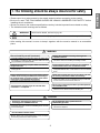
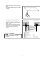
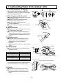
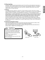
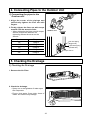
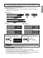
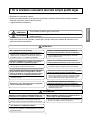
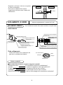
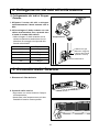
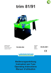
ISO 9001 - Cert. nº 0128/1
C
RT
IFI
E
D
E
A
IT
T
EM
QU
L
Y SY
AERMEC S.P.A.
S
Sostituisce il:
Replace:
ICXE_EXEIW
0312
5986100_00
ENGLISH
ITALIANO
CXE - EXE
M
MA
AN
NU
UA
ALLEE D
D’’IIN
NS
STTA
ALLLLA
AZ
ZIIO
ON
NEE • IIN
NS
STTA
ALLLLA
ATTIIO
ON
N B
BO
OO
OK
KLLEETT
Condizionatori d’ambiente e pompe di calore a due sezioni
Split system room air conditioners and heat pumps
• This unit is charged with new refrigerant, R-407C.
• Be sure to use proper tools for R-407C, when installing the unit.
• Please read this instruction sheet completely before installing the product.
• When the power cord is damaged, replacement work shall be performed by authorized
personnel only.
• Installation work must be performed in accordance with the national wiring standards by
authorized personnel only.
Indoor Unit
Air outlet vents
Air filters
Air intake vents
Remote Controller
Outdoor Unit
(Side)
(Rear)
Air intake vents
Air outlet vents
Control cover
(Side)
Air intake
vents
Air outlet
vents
Connecting wire
Piping
Drain hose
(Rear)
Control Cover
Connecting Wire
Connection Pipe
Drain Hose
ENGLISH
CEILING DUCT TYPE AIR CONDITIONERS
INSTALLATION INSTRUCTIONS
(Refrigerant : R-407C)
OUT-LINE OF INSTALLATION
1. The following should be always observed for safety ..............................3
Installation works
Installation Parts
2. Installation of Indoor, Outdoor unit
1) Selection of the best
• Four Type “A” screws
location............................4
• Connecting cable
• Level
• Screw driver
• Electric drill
• Hole core drill (ø70mm)
2) Indoor unit installation....5
3. Connecting Pipes to the Indoor Unit
1) Preparation of Piping...12
• Pipes: Gas side .....1/2", 5/8", 3/4"
•
•
Liquid side .............1/4",
Insulated drain hose
Insulation materials
Required tools
• Flaring Tools set
/8", 1/2"
3
4. Connecting Pipes to the Outdoor Unit
1) Connecting the pipes to
• Additional Drain hose
the Outdoor Unit ..........14
(Inner Dia...............25mm)
5. Checking the Drainage ..............................................................................14
6. Connecting Cables between Indoor Unit and Outdoor Unit
1) Connecting cables to the
• Screw driver
Indoor Unit ...................15
2) Clamping of cables ......15
3) Connecting cables to the
Outdoor Unit ................16
4) Form the pipings ..........17
7. Air Purging of the Connecting Pipes and the Indoor Unit ....................18
• Hexagonal Wrench (4mm/5mm)
• Gas-leak Detector
8. Group Control ............................................................................................19
9. Two Thermistor System ............................................................................19
10. Hight-Static Motor Connection(For 48K/60K Model) ............................20
11. E.S.P (External Static Pressure) Setting................................................21
12. How to set E.S.P?. ...................................................................................22
2
1. The following should be always observed for safety
WARNING
Could lead to death, serious injury, etc.
CAUTION
Could lead to serious injury in particular environments when operated incorrectly.
• After reading this manual, be sure to keep it together with the owner's manual in an accessible
place.
WARNING
Perform the installation securely referring to the
installation manual.
Do not install it yourself (customer).
• Incomplete installation could cause injury due to fire, electric shock,
the unit falling or a leakage of water. Consult the dealer from whom
you purchased the unit or special installer.
• Incomplete installation could cause a personal injury due to
fire, electric shock, the unit falling or a leakage of water.
Install the unit securely in a place which can bear the
weight of the unit.
Perform electrical work according to the installation
manual and be sure to use an exclusive circuit.
• When installed in an insufficient strong place, the unit could fall
causing injured.
• If the capacity of the power circuit is insufficient or there is
incomplete electrical work, it could result in a fire or an electric
shock.
Use the specified wires to connect the indoor and the
outdoor units securely and attach the wires firmly to
the terminal board connecting sections so the stress
of the wires is not applied to the sections.
Attach the electrical part cover to the indoor unit and
the service panel to the outdoor unit securely.
• If the electrical part cover if the indoor unit and/or the service
panel if the outdoor unit are not attached securely, it could result
in a fire or electric shock due to dust, water, etc.
• Incomplete connecting and fixing could cause fire.
Be sure to use the part provided or specified parts for
the installation work.
Check that the refrigerant gas do not leak after
installation is completed.
• The use of defective parts could cause an injury or leakage of
water due to a fire, electric shock, the unit falling, etc.
CAUTION
Perform the drainage/piping work securely
according to the installation manual.
Do not install the unit in a place where an
inflammable gas leaks.
• If there is a defect in the drainage/piping work, water
could drop from the unit and household goods could be
wet and damaged.
• If gas leaks and accumulates in the area surrounding the unit, it
could cause an explosion.
Do not install the electric heater
• Electric heater may cause deformation or fire of blower
and housing which were made of plastic.
3
ENGLISH
• Please report to or take consent by the supply authority before connecting to the system.
• Be sure to read "THE FOLLOWING SHOULD BE ALWAYS OBSERVED FOR SAFETY" before
installing the air conditioner.
• Be sure to observe the cautions specified here as they include important items related to safety.
• The indications and meanings are as follows.
2. Installation of Indoor, Outdoor Unit
1. Selection of the best location
Inspection hole
(600X600)
Control box
Top view
1) Indoor unit
1000
(unit: mm)
Select location
Install the air conditioner in the location that
satisfies the following conditions.
• The place shall easily bear a load exceeding
four times the indoor unit’s weight.
• The place shall be able to inspect the unit as
the figure.
• The place where the unit shall be leveled.
• The place shall allow easy water
drainage.(Suitable dimension “H” is necessary
to get a slope to drain as figure.)
• The place shall easily connect with the
outdoor unit.
• The place where the unit is not affected by an
electrical noise.
• The place where air circulation in the room will
be good .
• There should not be any heat source or steam
near the unit
600
Front
Front view
H
Su
nro
of
More than
30cm
Fe
ob nce
sta or
cle
s
More than
30cm
More than
70cm
2) Outdoor unit
• If an awning is built over the unit to prevent
direct sunlight or rain exposure, be careful
that heat radiation from the condenser is not
restricted.
• There should not be any animals or plants
which could be affected by hot air
discharged.
• Ensure the spaces indicated by arrows from
the wall, ceiling, fence or other obstacles.
Su
More than
30cm
nro
of
Fe
ob nce
sta or
cle
s
More than
30cm
More than
70cm
3) Piping length and the elevation
Capacity
18K BTU/h
24K BTU/h
36K BTU/h
48K BTU/h
60K BTU/h
Pipe Size
Length A(m)
(Diameter: Ø)
Gas
Liquid Standard Max.
1/4"
50
7.5
5/8"
1/4"
50
7.5
5/8"
1/4"
50
7.5
5/8"
3/8"
50
7.5
3/4"
1/2"
50
7.5
3/4"
Elevation B(m)
Standard
5
5
5
5
5
600
Max.
30
30
30
30
30
*Additional
refrigerant
(g/m)
30
30
40
40
40
• If 18K Model is installed at a distance of 15m, 225g of
refrigerant should be added (15-7.5) x 30g = 225g
• Capacity is based on standard length and maximun allowance
length is on the basis of reliability.
• Improper refrigerant charge may result in abnormal cycle.
4
Indoor unit
A
B
Outdoor unit
2. Indoor unit installation
ENGLISH
■ Installation of Unit
Install the unit above the ceiling correctly.
A
CASE 1
B
POSITION OF SUSPENSION BOLT
D
C
E
• Apply a joint-canvas between the unit and
duct to absorb unnecessary vibration.
• Apply a filter Accessory at air return hole.
(Unit:mm)
F
(G)
18K BTU/h
24K BTU/h
36K BTU/h
48K BTU/h
60K BTU/h
A
B
C
D
E
932
932
1232
1292
1292
880
880
1182
1230
1230
355
355
355
570.5
570.5
45.5
45.5
45.5
54
54
450
450
450
680
680
F (G)
30
30
30
30
30
87
87
87
120
120
H
I
750
750
830
1006
1006
163
163
186
294
294
H
1-3 mm
Capacity
I
Dimension
Drainage hole
CASE 2
M10 Nut
X4
(Local
M10 SP. washer X 4 supply)
M10 washer
X4
• Install the unit leaning to a drainage hole
side as a figure for easy water drainage.
M10 washer
X4
(Local
M10 SP. washer X 4 supply)
M10 Nut
X4
POSITION OF CONSOLE BOLT
• A place where the unit will be leveled and
that can support the weight of the unit.
• A place where the unit can withstand its
vibration.
• A place where service can be easily
performed.
5
• Select and mark the position for fixing
bolts.
• Drill the hole for set anchor on the face
of ceiling.
• Insert the set anchor and washer onto
the suspension bolts for locking the
suspension bolts on the ceiling.
• Mount the suspension bolts to the set
anchor firmly.
• Secure the installation plates onto the
suspension bolts (adjust level roughly)
using nuts, washers and spring
washers.
Old building
New building
1 Set anchor
2 Plate washer
3 Spring washer
4 Nut
5 Suspension
bolts
• Local supply
Set anchor
Plate washer
Spring washer
Nut
Suspension bolt
CAUTION
Tighten the nut and bolt to prevent
unit falling
6
- M10
- M10
- W3/8 or M10
- W3/8 or M10
CAUTION
Front of view
• The unit must be horizontal or declined to the drain hose connected when finished
installation.
1~3mm
Ceiling
CORRECT
INCORRECT
Drainage hole
CAUTION FOR GRADIENT OF
UNIT AND DRAIN PIPING
Drainage hole
Lay the drain hose with a downward
inclination so water will drain out.
Thermal insulator
(Local supply)
• Always lay the drain with downward
inclination (1/50 to 1/100).
Prevent any upward flow or reverse flow
in any part.
• 5mm or thicker formed thermal insulator
shall always be provided for the drain
pipe.
Drainage pipe
(Local supply)
Unit
Make sure to be closed.
Drainage hole
• Upward routing not
allowed
CORRECT
INCORRECT
Applied U-Trap Dimension
A ≥ 70mm
B ≥ 2C
C ≥ 2 x SP
SP = External Pressure
(mmAq)
Ex) External Pressure
= 10mmAq
A ≥ 70mm
B ≥ 40mm
C ≥ 20mm
• Install the P-Trap (or U-Trap) to prevent
a water leakage caused by the blocking
of intake air filter.
7
B
C
U-Trap
A
ENGLISH
1. Install declination of the indoor unit is very important for the drain of the duct type air
conditioner.
2. Minimum thickness of the insulation for the connecting pipe shall be 5mm.
• Drill the piping hole with 70mm dia, hole
core drill.
• Piping hole should be slightly slant to the
outdoor side.
WALL
Indoor
Outdoor
5~7mm
INSULATION, OTHERS
THERMAL INSULATION
Insulate the joint and tubes completely.
All thermal insulation must comply with local requirement.
INDOOR UNIT
Union for liquid pipe
Thermal insulator for refrigerant pipe
(Local supply) Thermal insulator for
piping(Local supply)
Refrigerant pipe and thermal
insulator(Local supply)
Hose clip for thermal insulator
(Local supply)
Overlap with thermal
insulator for piping.
Hose clip for thermal insulator(Local supply)
Make sure that there is no clearance here.
Thermal insulator for refrigerant pipe
(Local supply)
Union for gas pipe
REFRIGERANT PIPE
• Insulate and tape both the gas piping and
liquid piping.
Power cable
Liquid pipe
Tape
Gas pipe
Thermal insulator
TEST AND CHECK
■ After all workings are finished, check the working and operation.
• Air distribution
• Drain
• Gas leakage
• Wiring
• Lock-bolt
Is the air circulation good?
Is the drainage smoothly and no sweating?
Is the piping connection correctly?
Is the wiring connection correctly?
Is the lock-bolt of compressor loosened?
8
INSTALLATION OF REMOTE CONTROL BOX
Install the remote control box
and cord correctly.
• Although the room temperature sensor is in the indoor unit, the remote control box should
be installed in such places away from direct sunlight and high humidity.
INSTALLATION OF THE REMOTE CONTROL BOX
ROUTING OF THE REMOTE CONTROL CORD
• Select places that is not splashed by water.
• Select control position after receiving
customer approval.
• The room temperature sensor of the
thermostat for temperature control is built
in the indoor unit.
• This remote controller equipped with liquid
crystal display. If this position is higher or
lower, display is difficult to see.
(The standard height is 1.2~1.5m high)
• Keep the remote control cord away from
the refrigerant piping and the drain piping.
• To protect the remote control cord from
electrical noise, place the cord at least 5cm
away from other power cables. (Audio
equipment, Television set, etc)
• If the remote control cord is secured to a
wall, provide a trap at the top of the cord to
prevent water droplets from running.
ELECTRICAL WIRING TO THE INDOOR UNIT
Remote controller
(Main board)
CN REMO
CN REMO
Make sure that wire and terminal
numbers are matched on unit side
and remote controller side.
The maximum length of the cord is 100m.
If the length of the cord exceeds 50m, use a wire size greater than 0.5mm2.
WHEN THE REMOTE CONTROL BOX IS
INSTALLED WITH THE CORD EXPOSED.
DISASSEMBLING OF THE REMOTE CONTROLLER
Th
Front case
e lo
we
Lever carefully
the box open
using a screw
driver, etc.
rp
PROCEDURE OF INSTALLATION
1. Fix the under plate on the wall by self tapping
screws (accessory).
2. Make a slit (Part A) at the top side of the remote
control box by nipper.
3.Rout the cord as shown in the following figure. In
this case, push the cord into the around of
case(Part B).
4. Hook the remote control unit on the under plate.
art
Remote
control
box body
WHEN THE REMOTE CONTROL BOX IS
INSTALLED WITH THE CORD BURIED.
PROCEDURE OF INSTALLATION
1. Fix the under plate on the switch box by
screws(Local supply). In this case, fit the under
plate on the wall, and be careful of deformation.
2. Receive the remote control cord in the switch box.
3. Hook the remote control unit on the under plate.
Remote
control cord
(Part A)
Face of wall
Upper notch
Under plate
Tapping screw
(Local supply)
Upper flange
Push hand
(Part B)
Remote
control unit
Face of wall
Upper notch
Under plate
Remote
control unit
Screw
(Local supply)
Remote
control cord
Lower notch
Switch box
(Local supply)
Lower notch
FIXING OF REMOTE
CONTROL CORD
1. Fix the cord clamps on the wall
by ø3 tapping screws(Local supply).
2. Fix the remote control cord.
Cord
clamp
CAUTION
Display temperature can be different from actual room temperature if the remote controller is
installed at the place where sun-rays are falling directly or the place nearby heat source.
To narrow the gab between display temperature and actual room temp. install the remote controller
at proper place away from heat source.
9
ENGLISH
POINT OF REMOTE CONTROLLER INSTALLATION
REFRIGERANT PIPING
Perform the work according to the Service
Manual or Installation Guide.
• Use two spanners when connect the
refrigerant pipe to the unit.
• Make a bend with a radius as large as
possible.
• After completing the piping connection,
execute vacuum drying for the connecting
piping and the indoor unit.
• The vacuum drying must be carried out
using the service ports of both the liquid
and gas side valves.
• When piping work is finished, check all
joints.
Flared connection (Union)
Use a seemliness tube
Indoor
Factory charged
■ Add refrigerant if piping is over 7.5m.
Capacity
Addition volume
18K BTU/h
30 g/m
24K BTU/h
30 g/m
36K BTU/h
40 g/m
48K BTU/h
40 g/m
60K BTU/h
50 g/m
Flared connection
(Service valve, Ball valve)
Outdoor
INSTALLATION OF OUT DOOR UNIT
■ Select the following location
• A place where the air conditioner can
get good ventilation.
• A place where it shall not annoy the
neighbors.
• A place where the unit shall be leveled
and that can support the weight of unit
and withstand its vibrations.
Select a location that satisfies the following
conditions. Install the unit firmly in place.
Above 30Cm
Outdoor unit
Above 30Cm
Above 70Cm
Above 50Cm
Face of wall
■ Keep a maintenance space
10
ELECTRICAL WIRING
Perform the electrical wiring work according to
the electrical wiring connection.
Circuit Breaker
Main
power source
Outdoor
Indoor
Control terminal board
• Capacity of circuit breaker
Control box
Capacity
18K BTU/h
24K BTU/h
36K BTU/h
48K BTU/h
60K BTU/h
1 Phase
20A
25A
35A
-
Switch box
3 Phase
25A
25A
25A
A
A view
Remote
control cord
Cord clamper
1
Connection
cord between
the indoor unit
and the
outdoor unit
1
WIRING CONNECTION
Control box cover
(On which the Electric
Wiring Connection is put)
INDOOR UNIT
• Remove the control box cover for
electrical connection between the
indoor and outdoor unit.
(Remove crews ➀.)
• Use the cord clamper to fix the cord.
Cord
clamper
Cover control
OUTDOOR UNIT
Main terminal board
Control terminal board
• Remove the control cover for wiring
connection.
• Use the cord clamper to fix the cord.
• Earthing work
Connect the cable of diameter 1.6mm2
or more to the earthing terminal
provided in the control box and do
earthing.
Main terminal board
Control terminal board
Please check !!
Cover control
Cord
clamper
11
ENGLISH
• All wiring must comply with local
requirements.
• Select a power source that is capable of
supplying the current required by the air
conditioner.
• Use a recognized circuit breaker
between the power source and the unit.
A disconnection device to adequately
disconnect all supply lines must be
fitted.
3. Connecting Pipes to the Indoor Unit
3-1. Preparation of Piping
Main cause of gas leakage is defect in
flaring work. Carry out correct flaring work
in the following procedure.
Copper
tube
Slanted Uneven Rough
90°
1) Cut the pipes and the cable.
■ Use the accessory piping kit or the pipes
purchased locally.
■ Measure the distance between the
indoor and the outdoor unit.
■ Cut the pipes a little longer than
measured distance.
■ Cut the cable 1.5m longer than the pipe
length.
Pipe
Reamer
Point down
2) Burrs removal
■ Completely remove all burrs from the cut
cross section of pipe/tube.
■ Put the end of the copper tube/pipe to
downward direction as you remove burrs
in order to avoid to let burrs drop in the
tubing.
Flare nut
Copper tube
3) Putting nut on
■ Remove flare nuts attached to indoor
and outdoor units, than put them on
pipe/tube having completed burr
removal.
(Not possible to put them on after flaring
work)
Handle
4) Flaring work
■ Carry out flaring work using flaring tool
as shown below.
Outside Diameter
1/4"
3/8"
1/2"
5/8"
3/4"
"A"
0~0.5
0.5~0.8
0.5~0.8
0.8~1.0
1.0~1.3
Bar
Bar
"A"
Yoke
Cone
Copper pipe
Clamp handle
Red arrow mark
Smooth all round
Inside is shining without scratches.
Firmly hold copper tube in a bar(or die) as
indicated dimension in the table above.
= Improper flaring =
5) Check
■ Compare the flared work with figure.
■ If flare is noted to be defective, cut off
the flared section and do flaring work
again.
Even length
all round
12
Inclined Surface Cracked Uneven
damaged
thickness
6) Pipe bending
7) Brazing
In refrigerant piping, bending (in particular, acute bending) must be minimized to reduce
piping resistance. Bending is, however, necessary in some places by virtue of the installation
position of devices auxiliary to the packaged air conditioner, or of the building structure,
piping distance or finishing appearance. If a more acute bend is required than that attainable
by pipe bender, perform brazing using ready-made elbow. Aside from this function, brazing
also serves to connect straight pipes, generally using ready-made sockets. While brazing,
protect piping against heat with wet cloth to avoid damaging valve packing or burning
thermal insulator with burner heat. While brazing, blow inert gas (nitrogen gas or carbonic
gas) to prevent formation of oxidation film in copper piping; otherwise, the refrigerant circuit
will clog. The blowing of nitrogen gas (or carbonic gas) through 3-way valves is described in
the following:
8) Refrigerant piping(Flare piping)
When connecting piping, be sure to keep piping dry(keep piping away from water), clean
(keep piping away from dust) and airtight (avoid refrigerant leakage).
When connecting piping on rainy days or making a through-hole in wall, take due care to
prevent water or plaster from entering piping.
CAUTION
a. This procedure is designed to prevent
formation of oxidation film by filling piping
with inert gas. Note that excessive gas
pressure will generate pinholes at brazed
points.
(Nitrogen gas: Supply pressure
0.05~0.1kg/cm2G)
b. When supplying inert gas, be sure to open
one end of piping.
Water enters
13
Plaster enters
ENGLISH
Annealed copper pipe with small diameter (ø6.35 or ø9.52) can be easily bent manually. In
this case, secure large R(radius) for the bend section and gradually bend pipe. If annealed
copper pipe is large in diameter (ø15.88 or ø19.05), bend pipe with bender. Use bender
appropriate for the pipe diameter.
4. Connecting Pipes to the Outdoor Unit
1) Connecting the pipes to the
Outdoor unit
1. Align the center of the pipings and
sufficiently tighten the flare nut with
fingers.
2. Finally, tighten the flare nut with torque
wrench until the wrench clicks.
• When tightening the flare nut with torque
wrench, ensure the direction for
tightening follows the arrow on the
wrench.
Pipe size
Torque
1/4"
1.8kg.m
3/8"
4.2kg.m
1/2"
5.5kg.m
5/8"
6.6kg.m
3/4"
6.6kg.m
Outdoor unit
Gas side piping
(Bigger Dia.)
Liquid side piping
(Smaller Dia.)
Torque wrench
5. Checking the Drainage
1) Checking the Drainage
1. Remove the Air Filter.
2. Check the drainage.
• Spray one or two glasses of water upon
the evaporator.
• Ensure that water flows drain hose of
indoor unit without any leakage.
14
6. Connecting Cables between Indoor Unit and Outdoor Unit
■ Connect the wires to the terminals on the control board individually according to the
outdoor unit connection.
• Ensure that the color of the wires of outdoor unit and the terminal No. are the same as
those of indoor unit respectively
■ 18K/24K Btu
• Cooling only type
(380-415V3N~)
(220-240V~)
Terminals on the indoor unit
3(L) 4(N)
Terminals on the outdoor unit 1(L) 2(N)
3(L) 4(N) 5
5
6
1(L)
R
2(N)
T
N
POWER INPUT
POWER INPUT
POWER
INPUT
S
• Cooling & Heating type
Terminals on the indoor unit
3(L) 4(N)
5
6
7
Terminals on the outdoor unit 1(L) 2(N)
3(L) 4(N)
5
6
7
8
POWER
INPUT
■ 36K Btu
■ 48K/60K Btu
• Cooling only type
• Cooling only type
Terminals on the indoor unit
1
2
3
4
5
Terminals on the indoor unit
1(L) 2(N) 3
4
5
Terminals on the outdoor unit
1
2
3
4
5
Terminals on the outdoor unit 1(L) 2(N) 3
4
5
• Cooling & Heating type
• Cooling & Heating type
Terminals on the indoor unit
1
2
3
4
5
Terminals on the indoor unit
1(L) 2(N) 3
4
5
Terminals on the outdoor unit
1
2
3
4
5
Terminals on the outdoor unit 1(L) 2(N) 3
4
5
CAUTION
The power cord connected to the outdoor unit should be
The connecting cable connected to the indoor and outdoor
complied with the following specifications (Rubber
unit should be complied with the following specifications
insulation, type H05RN-F approved by HAR or SAA).
(Rubber insulation, type H05RN-F approved by HAR or SAA).
NORMAL CROSS-SECTIONAL AREA
GN
/YL
20
mm
Capacity
1 Phase
3 Phase
18K BTU/h
2.5mm2
-
24K BTU/h
2.5mm2
-
36K BTU/h
5.5mm2
2.5mm2
48K BTU/h
-
3.5mm2
60K BTU/h
-
3.5mm2
NORMAL
CROSS-SECTIONAL
AREA 0.75mm2 (18K/24K)
1.25mm2 (36K/48K/60K)
GN
/YL
20
mm
If the supply cord is damaged, it must be replaced by a special cord or assembly availible from the manufacturer of its service agent.
WARNING
Make sure that the screws of the terminal are free from looseness.
2) Clamping of cables
1) Arrange 2 power cables on the control panel.
2) First, fasten the steel clamp with a screw to the inner boss of control panel.
3) For the cooling model, fix the other side of the clamp with a screw strongly.
For the heat pump model, put the 0.75mm2 cable(thinner cable) on the clamp and tighten it
with a plastic clamp to the other boss of the control panel.
4) In Australia, the length of power supply cord measured from the entry of the power supply
cord to the middle of live pin on the power plug should be over 1.8m.
15
ENGLISH
1) Connecting cables to the Indoor Unit
3) Connecting the cable to the
Outdoor Unit
Outdoor unit
1. Remove the Cover control from the unit
by loosening a screw.
Connect the wires to the terminals on
the control board individually as
following.
Terminal block
Cord Clamper
2. Secure the cable onto the control board
with the holder (clamper).
Over 5mm
3. Refix the cover control to the original
position with the screw.
Cover control
Power supply
cord
Outdoor unit
Terminal block
Cord Clamper
Power supply
cord
Over 5mm
Cover control
CAUTION
After the confirmation of the above conditions, prepare the wiring as follows:
1) Never fail to have an individual power specialized for the air conditioner. As for the method
of wiring, be guided by the circuit diagram pasted on the inside of control box cover.
2) Provide a circuit breaker switch between power source and the unit.
3) The screw which fasten the wiring in the casing of electrical fittings are liable to come
loose from vibrations to which the unit is subjected during the course of transportation.
Check them and make sure that they are all tightly fastened. (If they are loose, it could give
rise to burn-out of the wires.)
4) Specification of power source
5) Confirm that electrical capacity is sufficient.
6) Be sure that the starting voltage is maintained at more than 90 percent of the rated voltage
marked on the name plate.
7) Confirm that the cable thickness is as specified in the power sources specification.
(Particularly note the relation between cable length and thickness.)
8) Never fail to equip a leakage breaker where it is wet or moist.
9) The following troubles would be caused by voltage drop-down.
• Vibration of a magnetic switch, damage on the contact point there of, fuse breaking,
disturbance to the normal function of a overload protection device.
• Proper starting power is not given to the compressor.
16
4) Form the pipings
Seal a small opening
around the pipings
with gum type sealer.
Drain hose
Taping
Pipings
Connecting
cable
Power supply
cord
In case of the Outdoor unit being installed
below position of the Indoor unit.
2. Tape the Pipings, drain hose and
Connecting Cable from bottom to top.
3. Form the pipings gathered by taping
along the exterior wall and fix it onto the
wall by saddle or equivalent.
Trap is required to prevent water
from entering into electrical parts.
Drain hose
Taping
Pipings
Connecting
cable
Power supply
cord
In case of the Outdoor Unit being installed
above position of the Indoor Unit.
Seal a small opening
around the pipings
with gum type sealer.
2. Tape the Pipings and Connecting cable
from bottom to top.
Trap
3. Form the pipings gathered by taping
along the exterior wall, and make the
trap prevent water from entering into the
room.
4. Fix the pipings onto the wall by saddle
or equivalent.
Trap
17
ENGLISH
1. Wrap the connecting portion of indoor
unit with the Insulation material and
secure it with two Plastic Bands. (for the
right pipings)
• If you want to connect an additional drain
hose, the end of the drain-outlet should
keep distance from the ground. (Do not
dip it into water, and fix it on the wall to
avoid swinging in the wind.)
7. Air Purging of the Connecting Pipes and the Indoor Unit
The air which contains moisture remaining in the refrigeration cycle may cause a malfunction
on the compressor.
1. Confirm that both the liquid side valve and the gas side valve are set to the closed position.
2. After connecting the piping, check the joints for gas leakage with gas leak detector.
3. Remove the service port nut, and connect the gauge manifold and the vacuum pump to the
service port by the charge hose.
4. Vacuum the indoor unit and the connecting pipes until the pressure in them lowers to below 76cmHg.
5. Remove the valve stem nuts, and fully open the stems of the 2-way and 3-way valves with a
hexagon wrench.
6. Tighten the valve stem nuts of the 2-way valve and 3-way valve.
7. Disconnect the charge hose and fit the nut to the service port.
(Tightening torque: 1.8kg.m)
Indoor unit
Liquid side
Closed
Outdoor unit
2-way valve/
3-way valve
Gas side
3-way
valve
Vaccum pump
OPEN
CLOSE
18
Closed
8. Group Control
Main PCB
Indoor Unit 1
Indoor Unit 2
Terminal(Local Supply)
Block
Connector
Terminal(Local Supply)
Block
Connector
RED(12V)
YL(SIGNAL)
BR(GND)
RED(12V)
YL(SIGNAL)
BR(GND)
Main PCB
#1
YL(SIGNAL)
BR(GND)
Indoor Unit 16
Terminal(Local Supply)
Block
Connector
Main PCB
#2
YL(SIGNAL)
BR(GND)
....
OPERATION
SET TEMP
Room Temp
Operation unit
03
FAN SPEED
HI
MED
LO
Time
Timer
On Off
Set no. Time 01
ZONE
YL(SIGNAL)
BR(GND)
Main PCB
#16
Connecting Cable(Local Supply)
....
AUTO SWING
YL(SIGNAL)
BR(GND)
SUB FUNCTION
AUTO Heater Preheat
JET Defrost Humidify
Filter Out door
1 2 3 4
Program set
05
07
09
11
13
15
17
19
21
23
Wired Remote Controller
(Standard)
Slide Switch2
Single
Group
Remote
Controller
PCB
• Using the supplied Wired Remote Controller, wire
them like above.
• Move slide switch 2 to "Group" position.
• Ensure that the color of wire.
9. Two Thermistor system
• Open the rear cover of Remote
Controller to set up the mode.
Slide Switch1
Slide Switch2
Room Temp. Sensing
Remo.
Indoor Unit
2 TH(Remo.+Indoor)
• Selectable options are three as follows.
- Remo: Sensing the room Temperature.
- Indoor Unit: Sensing the intake air into
indoor Unit.
- 2 TH: Sensing the lower temperature of
the two thermistors.
Single
Group
CAUTION
• On installing, don't impact to the PCB
and LCD display.
• Don't remove the protection sheet.
• Use the specified screw.
• On installing, turn off the main power.
• To set up the mode, adjust the slide
switch to desired mode position on
installing.
19
ENGLISH
It operates maximum 16 Units by only one Wired Remote Controller,
and each Unit starts sequentially to prevent overcurrent.
10. High-Static Motor Connection (For 48K/60K Model)
1. High-Static Motor Connection (For 48K Model)
Control box
• If working condition of indoor unit is higher than that of
standard static pressure (10mmAq) change the Indoor
Motor wire housing for standard motor housing for higher
external static Pressure (15mmAq).
Wire Color(YL, BK, BL, OR)
For Higher E.S.P(15mmAq)
Wire Color(BK, BL, RD, OR)
For Standard E.S.P(10mmAq)
2. Motor Connection (For 60K Model)
Control box
• If working condition of indoor unit is lower than that of
standard static pressure (10mmAq) change the Indoor
Motor wire housing for standard motor housing for lower
external static Pressure (6mmAq).
Wire Color(YL, BK, BL, OR)
For Standard E.S.P(10mmAq)
Wire Color(BK, BL, RD, OR)
For Lower E.S.P(6mmAq)
20
11. E.S.P.(External Static Pressure) Setting
ENGLISH
(1) Open the rear cover of the wired remote-controller to set the mode.
(2) Select one of three selectable modes as follows.
■ Without Zone System
1. Position V-H, F-H:
• This position sets the maximum E.S.P as a default set.
2. Position V-L:
• This position sets the minimum E.S.P as a default set.
■ With Zone System
1. Position V-H:
• Maximum E.S.P setting & Fan speed is varied according to the state of dampers by micom.
2. Position F-H:
• Maximum E.S.P setting & Fan speed doesn't vary according to the opening & Closing of dampers.
3. Position V-L:
• Minimum E.S.P setting & Fan speed is varied according to the state of dampers by micom.
* Maximum : 18K-8mmAq
24K-6mmAq
36K-8mmAq
48K-15mmAq
60K-15mmAq
Minimum : 0mmAq
(3) Move the slide switch to set position.
TH
R14H OP3
SW TH
V-L
R13H
OP2
REMO
MAIN
2TH
R12H
CO1H
OP1
R19H
R11H
OP7
R18H
R17H
F-H
OP6
LO
STAND
C070
V-H
R03S
HI
R04S
Slide switch for ceiling height
(4) Close the rear cover and check if it works normally.
CAUTION
• Select the position after checking duct work and E.S.P of the unit.
• Maunfactured in the position F-H.
21
HIGH
R02S
SW
R01S
OP5R16H
OP4
R15H
12. How to Set E.S.P?
Procedure of RPM change:
Ex) External Static pressure is 6mmAq for Model Name "LB-H1860 * * "
• To protect the unit, compressor is designed to be off during E.S.P. setting.
1
Push the "On/Off" button.
The unit will start.
AUTO SWING
OPERATION
SET TEMP
FAN SPEED
Room Temp
AUTO Heater Preheat
JET Defrost Humidify
Filter Out door
ZONE
1 2 3 4
Time
Timer
Operation unit
On Off
Set no. Time 01
2
03
Program set
05
07
09
11
13
15
17
19
21
23
Push the "Timer" and "Wind" button simultaneously for more then 3 seconds.
AUTO SWING
Timer
OPERATION
SET TEMP
Room Temp
FAN SPEED
Operation unit
03
SUB FUNCTION
HI
MED
LO
AUTO Heater Preheat
JET Defrost Humidify
Filter Out door
ZONE
1 2 3 4
Time
Timer
On Off
Set no. Time 01
3
SUB FUNCTION
HI
MED
LO
Program set
05
07
09
11
13
15
17
19
21
23
Push the "Up" of "Down" button for E.S.P adjustment.
And, adjust the number which you want.(In this example, the number is "215". Refer to the
table 1 on the next page.)
AUTO SWING
OPERATION
SET TEMP
Room Temp
FAN SPEED
AUTO Heater Preheat
JET Defrost Humidify
Filter Out door
ZONE
1 2 3 4
Time
Timer
Operation unit
On Off
Set no. Time 01
03
SUB FUNCTION
HI
MED
LO
Program set
05
07
09
11
13
15
17
19
21
23
Note: The range of selection is from 1~254. Since, the display is two Digit only.
If the range selection is above 100 then the third digit will appear in the screen as shown.
4
Shift the fan speed mode by pressing the fan speed button.
And then, Adjust numbers of next steps by repeating the stage 3.
(In this example, the numbers are "230" and "245" respectly)
5
Push the "Timer" and "Wind" button simultaneously for more than 3 seconds.
Then, Wind Data is memorized by the EEPROM of the main PCB.
AUTO SWING
OPERATION
SET TEMP
Room Temp
AUTO Heater Preheat
JET Defrost Humidify
Filter Out door
ZONE
1 2 3 4
Time
Timer
Operation unit
22
03
SUB FUNCTION
HI
MED
LO
Timer
On Off
Set no. Time 01
FAN SPEED
Program set
05
07
09
11
13
15
17
19
21
23
Static Pressure(mmAq)
0
2
Model Name Step(Hi/Med/Lo)
EXE180H
EXE240H
4
6
8
10
Setting Value
16.5 CMM
235
230
225
215
180
14.5 CMM
245
238
235
230
215
13 CMM
254
252
248
245
240
18 CMM
230
215
210
50
-
16.5 CMM
240
235
230
210
-
14 CMM
255
252
250
245
-
32 CMM
235
230
230
150
1
29 CMM
247
245
245
235
230
26.5 CMM
254
253
253
250
248
EXE360H
Note: 1. Be sure to set the value refering table 1. Unexpected set value will cause
mal-function.
2. Table 1 is based at 230V. According to the fluctuation of voltage, air flow rate
varies.
[Table. 2]
Static Pressure(mm Aq)
Model Name
EXE480H
EXE600H
(Standard)
EXE600H
(Low Static)
0
2
4
6
8
10
15
Step
CMM
CMM
CMM
CMM
CMM
CMM
CMM
High
48.5
46.5
45
43.5
42
40
40
Med
43
41.5
39.5
38
36.5
35
35
Low
39
37.5
36
34.5
33
31
30
High
58.5
57
55
53
51
49
44
Med
54
52.5
51
49
47
45
39
34
Low
49
47.5
46
44
42
40
High
54
52.5
51
49
47
45
Med
49
47.5
46
44
42
40
Low
44
42.5
41
39
37
35
1) The above table shows the correlation of External Static Pressure & AIR FLOW.
2) Duct work must be designed within the range of
on installing the unit.
3) Change the wiring diagram referring to page 20 of manual on condition fo High/Low Static
Pressure.
4) If duct work is designed under
Pressure applying air damper.
External Static Pressure, adjust the External Static
23
ENGLISH
[Table. 1]
Memo
24
INSTRUZIONI PER I'INSTALLAZIONE DEL
CONDIZIONATORE D'ARIA DI TIPO DA CONTROSOFFITTO A SCOMPARSA
(Refrigerante: R-407C)
Gruppo Interno
Prese d’aria di uscita
Filtri aria
Prese d’aria di entrata
Pannellino comandi
Gruppo Esterno
( Lato)
(Retro)
Prese d’aria di entrata
Prese d’aria di uscita
Coperchio di
controllo
( Lato)
Cavo di collegamento
Condutture
Tubo flessibile
di scarico
(Retro)
Prese d’aria di entrata
Prese d’aria di uscita
Coperchio di
controllo
Cavo di collegamento
Condutture
Tubo flessibile
di scarico
ITALIANO
• Unità con gas refrigerante R407C.
• In fase di installazione usare strumenti adatti per R407C.
• Si raccomanda di leggere completamente queste istruzioni prima di procedere con l’installazione del prodotto.
• Nel caso fosse necessario sostituire il cavo di alimentazione, la sostituzione deve essere effettuata solamente da
personale autorizzato.
• Il lavoro di installazione deve essere effettuato in conformità agli standard nazionali relativi agli impianti elettrici e
solamente da personale autorizzato.
SCHEMA DI INSTALLAZIONE
1. Per la sicurezza è necessario osservare sempre quanto segue ............3
Lavori di installazione
Componenti dell’installazione
Arnesi richiesti
2. Installazione dei gruppi Interno e Esterno
1) Selezione della posizione
migliore ..........................4
2) Installazione del gruppo
interno............................5
• Quattro viti di tipo “A”
• Cavo di collegamento
• Livella
• Cacciavite
• Trapano
• Punta trapano (D. 70mm)
3. Collegamento dei Tubi al Gruppo Interno
1) Preparazione delle
tubature. ......................12
• Tubi: lato gas..........1/2", 5/8", 3/4"
Lato liquido ...........1/4", 3/8", 1/2"
• Tubo flessibile di scarico
isolato
• Materiali di isolamento
• Corredo arnesi per la
svasatura
4. Collegamento dei Tubi al Gruppo Esterno
1) Collegamento dei tubi al
Gruppo Esterno ...........14
• Tubo flessibile di scarico
addizionale
(Diametro Interno..25mm)
5. Controllo dello scarico ..............................................................................14
6. Collegamento dei cavi tra Gruppo interno ed esterno
• Cacciavite
1) Collegamento dei cavi al
Gruppo Interno ............15
2) Bloccaggio dei Cavi .....15
3) Collegamento dei cavi al
Gruppo Esterno ...........16
4) Sagomatura dei tubi.....17
7. Spurgo dei Tubi di Collegamento e del Gruppo Interno ........................18
• chiave esagonale (4mm, 5mm)
• Rilevatore di fughe di gas
8. Controllo di gruppo ..................................................................................19
9. Il sistema a due termistori ........................................................................19
10. Connessione motore per alta pressione statica (solo modelli EXE480H/600H)....20
11. Come impostare la P.S.E(Pressione Statica Esterna) .........................21
12. Impostazione P.S.E ? ...............................................................................22
2
1. Per la sicurezza è necessario osservare sempre quanto segue
• Rispettare le normative vigenti.
• Osservare attentamente le avvertenze specificate in questo documento poichè includono
elementi importanti relativi alla sicurezza.
• I significati delle indicazioni:
ATTENZIONE
Può portare a lesioni gravi, morte ecc.
Può portare a lesioni gravi in ambienti particolari se utilizzati in
modo improprio.
• Dopo aver letto questo manuale, conservarlo sempre insieme al libretto di istruzioni in un
posto facilmente accessibile.
PERICOLO
Effettuare l’installazione seguendo tutti i parametri di
sicurezza facendo riferimento al manuale di installazione.
Non installare da soli (cliente)
• Una installazione incompleta può causare lesioni gravi a
causa di incendi, scossa elettrica, caduta del gruppo o
perdite di acqua. Consultare il rivenditore dal quale avete
acquistato il gruppo o un installatore specializzato.
• Una installazione incompleta può provocare lesioni personali
gravi in seguito ad incendi, scosse elettriche, caduta del
gruppo o perdite di acqua.
Installare saldamente il gruppo in un punto
che può sostenere il peso del gruppo
Effettuare i lavori sull’impianto elettrico facendo riferimento al
manuale di installazione ed assicurare l’uso di un circuito esclusivo.
• Se viene installato in un punto che non è sufficientemente
forte il gruppo può cadere causando lesioni.
• Se la portata del circuito elettrico è insufficiente o l’impianto elettrico
è incompleto si possono verificare incendi o scosse elettriche.
Usare i fili elettrici specificati per collegare saldamente i
gruppi interno ed esterno e collegare bene i cavi alle
sezioni di connessione del pannello terminale in modo
che lo stress dei fili non venga applicato alle sezioni.
Fissare bene il coperchio dei componenti elettrici al gruppo
interno ed il pannello di servizio al gruppo esterno.
• Se il coperchio del componente elettrico del gruppo
interno e/o il pannello di servizio del gruppo esterno
non sono ben fissati, si possono verificare incendi,
scosse elettriche a causa di polvere acqua ecc.
• Collegamenti o fissaggi incompleti possono
provocare incendi.
Usare solamente i componenti corretti forniti o i
componenti specificati per il lavoro di installazione.
Verificare che non ci siano fughe di gas refrigerante
una volta completata I'installazione.
• L’uso di componenti difettosi può provocare lesioni o
perdite di acqua inseguito a incendi, scosse elettriche,
caduta del gruppo ecc.
ATTENZIONE
Effettuare il lavoro relativo alle tubature/scarico con
la massima cura seguendo le istruzioni del manuale.
Non installare il gruppo in un luogo in cui ci
siano fughe di gas infiammabile.
• Se ci sono difetti nel lavoro di tubature/scarico, è possibile che
l’acqua goccioli dal gruppo, e beni personali e mobili casa
potrebbero bagnarsi ed essere irrimediabilmente danneggiati.
• Se una fuga di gas si accumula nell’area circostante il
gruppo si potrebbero verificare esplosioni.
Non installare il riscaldamento elettrico
• Il riscaldamento elettrico può provocare deformazione o
incendio del ventilatore e dell'alloggiamento che sono
costituiti di plastica.
3
ITALIANO
PERICOLO
2. Installazione dell'unità interna ed esterna
1) Unità interna
Selezione della posizione
Installare il condizionatore d’aria nel punto che soddisfa
le seguenti condizioni.
• Il punto può facilmente sostenere quattro volte il peso
del gruppo interno.
• In questo punto sarà agevole ispezionare il gruppo
come indicato dall’illustrazione.
• Un punto in cui il gruppo sarà messo a livello.
• Un punto che permetta un agevole scarico dell’acqua.
(Le dimensioni idonee “H” sono necessarie per ottenere
una curva per scaricare come dall’illustrazione.)
• Un punto in cui sia agevole effettuare il collegamento
con il gruppo esterno.
• Un punto in cui il gruppo non sia influenzato da disturbi
elettrici.
• Un punto in cui la circolazione di aria nella stanza sia
buona.
• L’assenza di fonti di calore o vapore nelle vicinanze
dell'unità.
Foro di ispezione
(600X600)
Scatola di controllo
1000
Vista superiore
(unità: mm)
1. Selezione della migliore posizione
600
600
Fronte
Vista frontale
H
Ten
da
Oltre
30cm
St
ec
os cato
tac o
oli
Oltre
30cm
Oltre
70cm
2) Unità esterna
• Nel caso venga costruita una tenda sopra l'unità per
prevenire la luce diretta del sole o l’esposizione alla
pioggia assicurarsi che non venga limitata la
radiazione di calore dal condensatore.
• Non ci devono essere animali o piante che possano
essere investiti dal calore rilasciato.
• Assicurare la presenza degli spazi indicati dalle
frecce dal muro, soffitto, steccato o altri ostacoli.
Ten
Oltre
30cm
da
St
ec
os cat
tac o o
oli
Oltre
30cm
Oltre
70cm
3) Lunghezza ed elevazione dei tubi
Modello
180
240
360
480
600
Dimensioni del tubo
Lunghezza A (m) Elevazione B (m) Carica
(Diametro:Ø)
aggiuntiva
Gas
Liquido Nominale Massima Nominale Massima
1/4"
30
5
50
7.5
5/8"
30
1/4"
30
5
50
7.5
5/8"
30
1/4"
30
5
50
7.5
5/8"
40
3/8"
30
5
50
7.5
3/4"
40
1/2"
30
5
50
7.5
3/4"
40
Unità interna
• Se i modelli 180 vengono installati ad una distanza di 15m, sarà
necessario aggiungere 225g di refrigerante (15-7.5) x 30g = 225g
• La capacità si basa sulla lunghezza standard e la lurghezza massima
permessa viene calcolata sulla base dell'affidabilità.
• Una carica non corretta del refrigerante potrebbe causare un
funzionamento anormale.
4
A
B
Unità esterna
2.Installazione dell'unità interna
■ Installazione dell'unità
Installare correttamente sul soffitto
A
B
CASO 1
POSIZIONE DEL BULLONE DI SOSPENSIONE
F
(G)
Dimensioni
A
B
C
D
E
932
932
1232
1292
1292
880
880
1182
1230
1230
355
355
355
570.5
570.5
45.5
45.5
45.5
54
54
450
450
450
680
680
F (G)
H
I
750
750
830
1006
1006
163
163
186
294
294
30
30
30
30
30
87
87
87
120
120
I
180
240
360
480
600
1-3 mm
Capacità
H
Foro di scarico
CASO 2
Dado M10
• Installare l'unità in pendenza verso il foro
di scarico come indicato dalla figura per
facilitare lo scarico dell’acqua.
X4
Rondella Dist M10 SP X 4 (Fornitura
locale)
Rondella M10 X 4
Rondella M10 X 4
POSIZIONAMENTO DELL'UNITA
Rondella Dist. M10 X 4 (Fornitura
locale)
Dado M10
X4
• Un punto dove l'unità é a livello ed il suo
peso può essere sostenuto.
• Un punto in cui l'unità può sopportare le
vibrazioni
• Un punto che sia facile da raggiungere
per la manutenzione.
5
ITALIANO
D
C
E
• Applicare un giunto antivibrante tra
l'unità e il canale al fine di assorbire le
vibrazioni inutili.
• Applicare un accessorio filtro sul foro di
ritorno dell’aria
(Unit:mm)
• Selezionare e contrassegnare la
posizione di fissaggio dei bulloni.
• Praticare un foro per inserire gli
ancoraggi sul soffitto.
• Inserire l’ancoraggio e la rondella sui
bulloni di sospensione per bloccare i
bulloni di sospensione al soffitto.
• Montare i bulloni di sospensione per
ancorare saldamente.
• Fissare le piastre di installazione sui
bulloni di sospensione (regolare il livello
a occhio) usando dadi, rondelle e
rondelle elastiche.
Costruzione
vecchia
Costruzione
nuova
1 Ancoraggio
2 Rondella piastra
3 Rondella elastica
4 Dado
5 Bullone di
sospensione
• Fornitura locale:
Ancoraggio
Rondella piastra
Rondella elastica
Dado
Bullone di sospensione
ATTENZIONE
Stringere il dado e bullone per evitare la
caduta del gruppo.
6
- M10
- M10
- W3/8 or M10
- W3/8 or M10
ATTENZIONE
1. La pendenza di installazione dell'unità interna è particolarmente importante nei
modelli canalizzati.
2. Lo spessore minimo dell’isolamento dei tubi di collegamento deve essere di 5 mm.
Vista di fronte
ITALIANO
• Il gruppo deve essere orizzontale e in pendenza verso il tubo di scarico.
1~3mm
SOFFITTO
CORRETTO
Foro di scarico
SCORRETTO Foro di scarico
Disporre il tubo flessibile di scarico con
una inclinazione verso il basso per facilitare
lo scarico dell'acqua.
ATTENZIONE PER LA PENDENZA
DEL TUBO DI SCARICO
Isolatore termico
(Fornitura locale)
• Disporre sempre lo scarico con una
inclinazione verso il basso (1/50 a
1/100).
Gruppo
Evitare percorsi ascendenti.
• Il tubo di scarico deve essere sempre
fornito di isolamento termico sagomato
dello spessore di 5mm o superiore.
Verificare che sia chiuso
CORRETTO
SCORRETTO
Dimensioni applicate sifone a U
A ≥ 70mm
B ≥ 2C
C ≥ 2 x SP
SP = Pressione esterna
(mmAq)
Es) Pressione esterna
= 10mmAq
A ≥ 70mm
B ≥ 40mm
C ≥ 20mm
• Installare il sifone intercettatore a
P (o sifone a U) per prevenire le
perdite di acqua provocate dal
blocco del filtro di aspirazione.
7
Tubo di scarico
(Fornitura locale)
Foro di scarico
• La disposizione del
tubo verso l'alto
non è permessa.
B
C
Sifone a U
A
• Praticare un foro per i tubi con una punta
di 70mm di diametro.
• Il foro per la tubatura deve essere
leggermente inclinato verso il basso dal
lato esterno.
ISOLAMENTO, E VARIE
ISOLAMENTO TERMICO
MURO
Interno
Esterno
5~7mm
Isolare completamente i raccordi ed i tubi.
Tutto l’isolamento termico deve essere conforme ai requisiti locali.
Unità interna
Isolatore termico per tubo refrigerante
(fornitura locale)
Isolatore termico per tubi
(fornitura locale)
Raccordo per tubo del liquido
Tubo refrigerante e isolatore termico
(fornitura locale)
Morsetto per tubo flessibile per isolatore
termico (fornitura locale)
Isolatore termico per tubo
refrigerante (fornitura locale)
Parte sovrapposta con
isolatore termico per tubature
(Fornitura locale)
Morsetto per tubo flessibile per isolatore termico
(fornitura locale)
Assicurarsi che non ci sia luce in questa posizione.
Raccordo per tubo gas
Tubo refrigerante
Isolare con nastro sia le condutture del
gas che le condutture del liquido.
Cavo di alimentazione
Tubo liquido
Nastro
Tubo gas
Isolatore termico
Prove e controlli
■ Una volta finito il lavoro, eseguire i seguenti controlli.
• Distribuzione aria
La circolazione dell’aria è soddisfacente?
• Scarico
Lo scarico è regolare e senza gocciolamenti?
• Fughe di gas
I collegamenti dei tubi sono corretti?
• Cablaggio
Le connessioni dei cavi sono corrette?
• Bullone di bloccaggio
Il bullone di bloccaggio del compressore è allentato?
8
INSTALLAZIONE DELLA SCATOLA DEL TELECOMANDO
Installare correttamente il cavo e la
scatola di controllo del telecomando.
PUNTO DI INSTALLAZIONE DEL TELECOMANDO
• Nonostante nell'unità interna sia presente un sensore della temperatura dell’ambiente, la scatola del
telecomando deve essere installata in punti lontani dalla luce diretta del sole o di alta umidità.
INSTALLAZIONE DELLA SCATOLA DEL TELECOMANDO
DISPOSIZIONE DEL CAVO DEL TELECOMANDO
• Tenere il cavo del telecomando lontano
dalle tubature refrigeranti e le tubature di
scarico.
• Per schermare il cavo del telecomando
da disturbi elettrici, disporre il cavo a 5
cm da altri cavi di alimentazione.
(Apparecchi audio, televisore ecc.)
• Se il cavo del pannellino comandi viene
fissato ad un muro inserire un
separatore nella sezione superiore del
cavo per evitare lo sgocciolare di acqua.
CABLAGGIO ELETTRICO DELL'UNITA INTERNA
Pannellino comandi
(Pannello principale)
CN REMO
CN REMO
Verificare che i numeri di filo e
di terminale siano combinati sul
lato unità e sul lato telecomando.
La lunghezza massima del cavo è 100 m.
Se la lunghezza del cavo supera 50m, usare un filo con sezione superiore a 0,5mm2
NEL CASO DI INSTALLAZIONE DI SCATOLA DEL
PANNELLINO COMANDI CON CAVO A VISTA
SMONTAGGIO DEL PANNELLINO COMANDI
Scatola frontale
Se
zio
ne
i
nfe
r
PROCEDURE DI INSTALLAZIONE
1. Fissare la sottopiastra al muro con viti autofilettanti.
2. Praticare una fessura (Parte A) sul lato superiore
della scatola pannellino comandi con una tenaglia.
3. Far passare il cavo come indicato nella figura che
segue. In questo caso premere il cavo intorno alla
scatola (Parte B)
4. Agganciare l’unità del telecomando sulla
Parete
sottopiastra
ior
Fare leva con attenzione
usando un cacciavite
per aprire la scatola
e
Corpo scatola del
telecomando.
NEL CASO DI INSTALLAZIONE DI SCATOLA DEL
TELECOMANDO CON CAVO INCASSATO
PROCEDURE DI INSTALLAZIONE
1. Fissare la sottopiastra sulla scatola degli interruttori con delle
viti (fornitura locale). In questo caso inserire la piastra sul muro
facendo attenzione a non deformarla.
2. Infilare il cavo delpannellino comandi nella scatola degli
interruttori.
3. Agganciare l’unità del pannellino comandi sulla sottopiastra.
Dentellatura Superiore
Sottopiastra
Vite autofilettante
(Parte A)
(Fornitura locale)
Flangia superiore
Premere
(Parte B)
Cavo del
pannellino comandi
Unità di
Dentellatura
pannellino comandi inferiore
Parete
Dentellatura superiore
Sottopiastra
FISSAGGIO DEL
CAVO DEL TELECOMANDO
Unità pannellino comandi
Vite (fornitura locale)
Morsetto
per cavo
1. Fissare le reggette del cavo sul muro
usando viti autofilettanti del 3ÿ
(fornitura locale)
2. Fissare il cavo del pannellino comandi.
Cavo del pannellino comandi
Dentellatura inferiore
Scatola interruttore
ATTENZIONE
La temperatura indicata sul display può essere differente dalla temperatura della stanza se il pannellino
comandi è installato in un luogo esposto a raggi diretti del sole o vicino a una fonte di calore.
Per ridurre la differenza tra la temperatura della stanza e quella indicata sul display, installare il pannellino
comandi in un luogo idoneo lontano da fonti di calore.
9
ITALIANO
• Selezionare punti che non siano sottoposti agli
schizzi d’acqua
• Selezionare una posizione per il controllo dopo
avere ricevuto l’approvazione del cliente.
• Il sensore della temperatura dell’ambiente del
termostato per il controllo della temperatura è
inserito nell'unità interna.
• Il telecomando è fornito di display a cristalli
liquidi. Se la posizione è troppo alta o troppo
bassa il display sarà difficile da vedere.
(L’altezza standard è 1,2-1,5 m di altezza)
TUBATURE DEL REFRIGERANTE
Effettuare il lavoro come indicato dal Manuale di
servizio o di installazione.
• Usare due chiavi per collegare il tubo
refrigerante al gruppo.
• Piegare con un raggio il più ampio
possibile.
• Completati i collegamenti dei tubi,
eseguire il vuoto del circuito frigorifero.
• La fase di vuoto del circuito frigorifero
deve essere eseguita con valvole del
liquido e del gas aperte.
• Terminato il lavoro controllare tutte le
giunture.
Collegamento svasato
(raccordo)
Usare un tubo senza
giunzioni
Interno
Caricato dalla fabbrica
■ Aggiungere refrigerante quando la
lunghezza delle tubature supera 7.5 m.
Capacità
Volume da aggiungere
180
30 g/m
240
30 g/m
360
40 g/m
480
40 g/m
600
50 g/m
Collegamento svasato
(Valvola di servizio,
valvola a sfera)
Esterno
INSTALLAZIONE DEL GRUPPO ESTERNO
■ Selezionare una posizione come
segue
• Un punto in cui il condizionatore riceva
una buona ventilazione
• Un punto in cui non dia fastidio ai vicini
• Un punto in cui l'unità sia a livello e
possa sostenere il peso che e
sopportare le vibrazioni.
Selezionare una posizione che soddisfi le seguenti
condizioni. Installare l'unità in maniera solida e sicura.
Superiore a 30Cm
unità esterna
Superiore a 30Cm
Superiore a 70Cm
Superiore a 50Cm
Fronte della parete
■ Assicurare gli spazi tecnici per la
manutenzione
10
IMPIANTO ELETTRICO
Effettuare i lavori dell’impianto elettrico seguendo
gli schemi di connessione.
Capacità
180
240
360
480
600
1 Fase
20A
25A
35A
-
Interruttore automatico
Alimentazione
principale
Scatola interruttori
Esterno
Interno
Pannello terminale del cavo
Vista A
A
Scatola di
controllo
3 Fasi
25A
25A
25A
Cavo
pannellino
comandi
1
Morsetto
per cavo
1
Cavo di collegamento tra il
gruppo interno e il gruppo
esterno
Coperchio della scatola di controllo
(Su questo viene inserito il collegamento
del cavo elettrico)
COLLEGAMENTI ELETTRICI
UNITA INTERNA
• Rimuovere il coperchio della scatola di
controllo tra i gruppi interno e esterno
(rimuovere due viti).
• Usare un morsetto per cavi per fissare
il cavo.
Pannello principale
dei terminali
Pannello terminale
di controllo
Morsetto
per cavi
Coperchio
di controllo
UNITA ESTERNA
• Rimuovere il coperchio per effettuare il
collegamento dei fili.
• Usare un morsetto per cavi per fissare il
cavo.
• Lavoro di messa a terra. Collegare un
cavo del diametro di 1,6mm2 o superiore
al terminale di terra fornito sulla scatola
di controllo e mettere a terra.
Pannello principale
dei terminali
Pannello terminale
di controllo
Per favore verificare!!
Coperchio
Morsetto
per cavi
11
ITALIANO
• L’impianto elettrico deve essere
conforme ai requisiti locali.
• Selezionare una fonte di alimentazione
che possa alimentare la corrente
richiesta dal condizionatore d’aria.
• Usare un interruttore automatico
omologato tra l’alimentazione ed il
gruppo. Deve essere installato anche
un dispositivo di sezionamento, per
scollegare in modo adeguato tutte le
linee di alimentazione.
• Interruttore automatico
3. Collegamento dei tubi all'unità interna
3-1 Preparazione dei tubi
Tubo di rame
La causa principale delle fughe di gas sono difetti
nel lavoro di svasatura. Effettuare correttamente il
lavoro di svasatura seguendo queste istruzioni.
Inclinato Impari Grezzo
90°
1) Tagliare il tubo e il cavo
■ Usare il corredo per tubi accessorio o i
tubi acquistati localmente.
■ Misurare la distanza tra gruppo interno e
gruppo esterno.
■ Tagliare i tubi in lunghezza leggermente
superiore a quella misurata.
■ Tagliare il cavo 1,5 m più lungo della
lunghezza del tubo.
Tubo
Alesatore
Punta verso
il basso
2) Rimozione delle bavature
■ Rimuovere completamente le bavature
dalla sezione tagliata del tubo.
■ Volgere l’estremità del tubo di rame
verso il basso per evitare la caduta delle
bavature all’interno dei tubi.
Dado svasato
Tubo di rame
3) Inserimento del dado
■ Rimuovere i dadi svasati collegati ai
gruppi interno ed esterno, poi inserirli sul
tubo dopo avere terminato la rimozione
delle bavature. (Non è possibile inserirli
dopo aver effettuato il lavoro di
svasatura.
Manico
4) Lavoro di Svasatura
Barra
■ Usare l’arnese di svasatura indicato
sotto per effettuare il lavoro di svasatura.
"A"
Barra
Morsetto
Cono
Diametro esterno
1/4"
3/8"
1/2"
5/8"
3/4"
"A"
0~0.5
0.5~0.8
0.5~0.8
0.8~1.0
1.0~1.3
Tubo di rame
Manico del morsetto
Liscio per tutta la circonferenza
L'interno lucido senza graffi.
Tenere ben saldo il tubo di rame in una
barra o forma come indicato nella tabella
delle dimensioni riportata in precedenza.
5) Controllo
■ Confrontare il lavoro di svasatura con
l’illustrazione.
■ Se la svasatura sembra difettosa , tagliare
la sezione svasata e rifare la svasatura.
Freccia rossa
= Svasatura scorretta =
Inclinato Superficie Spaccato Spessore
danneggiata
irregolare
Lunghezza uguale
per tutta la circonferenza
12
6) Piegatura dei tubi
I tubi di rame ricotto di piccolo diametro (ø 6,35 0 ø 9,52) possono essere facilmente piegati
manualmente. In questo caso formare un R (raggio) ampio per la sezione da piegare e
piegare gradualmente il tubo. Se il tubo di rame ricotto è di diametro grande (ø 15,88 o
ø 19,05) piegare il tubo con un piegatubi. Usare il piegatubi adeguato al diametro del tubo.
7) Brasatura
8) Tubature del refrigerante (tubature svasate)
Nel collegamento dei tubi, mantenere i tubi asciutti (tenere i tubi lontani dall’acqua) puliti
(tenere lontano dalla polvere) e tenuta stagna (evitare perdite di refrigerante). Evitare che
entrino acqua o polvere nel condizionatore se esso viene collegato in un giorno di pioggia o
se viene effettuato un buco passante nella parete.
ATTENZIONE
a. Questa procedura è stata studiata
per impedire la formazione della
pellicola di ossidazione riempiendo i
tubi con gas inerte. Notare che una
pressione eccessiva di gas genera
punture di spillo nei punti brasati.
(Azoto: pressione di alimentazione
0,05-0,1kg/cm2G)
b. Nel alimentare gas inerte mantenere
aperta un’estremità del tubature.
Acqua entra
13
Intonaco entra
ITALIANO
Nelle tubature del refrigerante la piegatura deve essere minimizzata (ed in particolare
piegature ad angoli acuti) al fine di ridurre la resistenza delle tubature. Comunque, la
piegatura è necessaria in alcuni punti a causa della posizione di dispositivi ausiliari al
condizionatore d’aria o struttura dell’edificio, distanza delle tubature o aspetto finito. Se viene
richiesta una piegatura maggiore a quella ottenibile con un piegatubi, effettuare la brasatura
utilizzando un gomito già preparato. Oltre a questa funzione la brasatura serve per collegare
tubi diritti usando, generalmente, innesti già preparati. Durante la brasatura proteggere il
tubo dal calore con uno straccio bagnato per evitare danni alla guarnitura della valvola o
bruciare l’isolatore termico con il calore della fiaccola. Durante la brasatura soffiare gas
inerte (azoto o carbonio) per impedire la formazione di una pellicola di ossidazione nelle
tubature di rame; in caso contrario il refrigerante si intaserebbe. La soffiatura dell’azoto
(carbonio) attraverso le valvole a tre vie è descritta di seguito.
4. Collegamento dei tubi all'unità esterna
1) Collegamento dei tubi al Gruppo
Esterno
1. Allineare il centro dei tubi e stringere
sufficientemente il dado svasato con le
dita.
2. Infine stringere il dado svasato con una
chiave torsiometrica fino a quando non
si sente lo scatto della chiave.
• Nello stringere il dado svasato con la
chiave torsiometrica assicurarsi che la
direzione di serraggio corrisponda alla
freccia sulla chiave.
Chiave torsiometrica
Torsione
1/4"
1.8kg.m
3/8"
4.2kg.m
1/2"
5.5kg.m
5/8"
6.6kg.m
3/4"
6.6kg.m
Gruppo Esterno
Tubature lato gas
(Diametro maggiore)
Tubature lato liquido
(Diametro minore)
Chiave torsiometrica
5. Controllo dello Scarico
1) Controllo dello scarico
1. Rimuovere il filtro dell’aria
2. Controllo dello scarico
• Spruzzare uno o due bicchieri d’acqua
sull’evaporatore.
• Assicurarsi che l’acqua scorra nel tubo
flessibile di scarico senza perdite.
14
6. Collegamento dei cavi tra Unità interna e unità esterna
1) Collegamento dei cavi all'unità interna
■ Collegare i fili ai terminali sul pannello di controllo singolarmente seguendo i collegamenti al
all'unità esterna
• Verificare che il colore dei fili del gruppo esterno ed i numeri di terminale siano gli stessi a
quelli usati sul gruppo interno rispettivamente.
■ 180H/240H
(220-240V~)
• Modello solo freddo
(380-415V3N~)
Terminali sull'unità esterna
1(L) 2(N)
5
6
1(L)
Alimentazione
in entrata
• Tipo refrigerante e riscaldante
Terminali sull'unità esterna
1(L) 2(N)
R
S
T
N
3(L) 4(N) 5
Entrada de
corriente
Terminali sull'unità interna
2(N)
3(L) 4(N)
5
6
7
3(L) 4(N)
5
6
7
Alimentazione
in entrata
8
Entrada de
corriente
■ 360H
■ 480H/600H
• Modello solo freddo
• Modello solo freddo
Terminali sull'unità interna
1
2
3
4
5
Terminali sull'unità interna
1(L) 2(N) 3
4
5
Terminali sull'unità esterna
1
2
3
4
5
Terminali sull'unità esterna
1(L) 2(N) 3
4
5
• Tipo refrigerante e riscaldante
• Tipo refrigerante e riscaldante
Terminali sull'unità interna
1
2
3
4
5
Terminali sull'unità interna
1(L) 2(N) 3
4
5
Terminali sull'unità esterna
1
2
3
4
5
Terminali sull'unità esterna
1(L) 2(N) 3
4
5
ATTENZIONE
Il cavo di alimentazione collegato all'unità esterna deve
Il cavo di collegamento alle unità deve essere conforme alle s
(Isolamento di gomma, tipo HO5RN.F approvato da
essere conforme alle seguenti specifiche (Isolamento di
HAR o SAA)
gomma, tipo Ho5RN-F approvato HAR o SAA)
SEZIONE TRASVERSALE NORMALE
GN
/YL
20
mm
Capacità
1 Fase
3 Fase
18K BTU/h
2.5mm2
-
24K BTU/h
2.5mm2
-
36K BTU/h
5.5mm2
2.5mm2
48K BTU/h
-
3.5mm2
60K BTU/h
-
3.5mm2
GN
SEZIONE
TRASVERSALE NORMALE
0,75mm2 (18K/24K)
1,25mm2 (36K/48K/60K)
/YL
20
mm
Se il cavo di alimentazione è danneggiato deve essere sostituito da un cavo speciale o assemblaggio fornito dal
fabbricante o servizio di assistenza.
2) Bloccaggio dei Cavi
1) Sistemare 2 cavi sul pannello di controllo.
2) Prima fissare il morsetto di acciaio con una vite alla borchia interna del pannello di controllo.
3) Nel modello refrigerante fissare saldamente l’altra estremità del morsetto. Nel modello con pompa
calore inserire il cavo da 0,75mm2 (cavo più fine) sul morsetto e stringere con il morsetto di plastica
all’altra borchia del pannello di controllo.
PERICOLO
Verificare che le viti del terminale non siano allentate.
15
ITALIANO
3(L) 4(N)
Terminali sull'unità interna
3) Collegamento del cavo dell'unità
esterna
1. Rimuovere il coperchio del gruppo
allentando la vite. Collegare
singolarmente, come segue, i fili ai
terminali sul pannello di controllo.
2. Fissare il cavo sul pannello di controllo
con un morsetto.
3. Rimettere il coperchio nella posizione
originale con la vite.
Gruppo esterno
Morsettiera
Morsetto
per cavo
Oltre 5mm
Coperchio
di controllo
Power supply
cord
Gruppo esterno
Morsettiera
Morsetto per cavo
Cavo di
alimentazione
Oltre
5mm
Coperchio di controllo
ATTENZIONE
Dopo aver confermato le condizioni di cui sopra procedere come segue:
1) Predisporre sempre una linea di corrente dedicata per il condizionatore d’aria. Per
quanto riguarda il metodo di cablaggio, seguire lo schema circuitale riportato
all’interno del coperchio della scatola di controllo.
2) Inserire un interruttore automatico tra alimentazione e gruppo.
3) La vite che fissa il fascio di conduttori all’interno dell’armadietto potrebbe allentarsi
a causa delle vibrazioni alle quali viene sottoposto il gruppo durante il trasporto.
Controllarle e verificare che siano saldamente fissate. (Nel caso siano allentate si
potrebbero bruciare i fili.)
4) Specifiche di alimentazione
5) Assicurarsi che l’energia elettrica fornita sia sufficiente
6) Assicurarsi che il voltaggio di partenza venga mantenuto ad oltre il 90 per cento del
voltaggio nominale riportato sulla targhetta di identificazione.
7) Assicurarsi che lo spessore del cavo sia quello riportato nelle specifiche della fonte
di alimentazione.
8) Installare sempre un interruttore per perdite nei punti bagnati o umidi.
9) I seguenti problemi possono essere causati da un calo di corrente.
• Vibrazioni di un interruttore magnetico, danni sul punto di contatto, fusibili saltati, disturbi
alle normali funzioni del dispositivo di protezione da sovraccarichi.
• Il compressore non riceve l’alimentazione adeguata per la partenza.
16
4) Sagomatura delle tubature
1. Avvolgere il segmento di connessione al
gruppo interno con materiale isolante e
fissarlo con due Fascette di Plastica
(Per le tubature corrette).
• Se si desidera collegare un ulteriore tubo
flessibile di scarico, l’estremità dell’uscita
dello scarico deve essere tenuta a una
certa distanza da terra (Non immergere in
acqua) e fissata.
Sigillare il piccolo spazio
intorno al tubo con un
sigillante di tipo gommoso.
Tubo flessibile
di scarico
Fasciatura
Tubature
Cavo di
alimentazione
Nel caso in l'unità esterna venga installata .
2. Fasciare con nastro le tubature, tubo
flessibile di scarico e cavo di
collegamento dal basso all’alto.
E’ necessario un separatore per
evitare che l’acqua entri nelle
componenti elettriche.
3. Sagomare le tubature raccolte
fasciandole lungo la parete esterna e
fissandole alla parete mediante una
sella o equivalente.
Tubo flessibile
di scarico
Fasciatura
Tubature
Cavo di
collegamento
Cavo di
alimentazione
Nel caso l'unità esterna venga installata in
posizione superiore all'unità interna.
Sigillare il piccolo spazio attorno al
tubo con sigillante di tipo gommoso.
2 Fasciare con nastro le tubature, tubo
flessibile di scarico e cavo di
collegamento dal basso all’alto.
Sifone
3 Sagomare le tubature raccolte
fasciandole con nastro lungo il muro
esterno, e facendo un pozzetto per
evitare che l’acqua entri nell’ambiente
interno.
4. Fissare le tubature alla parete con una
sella o equivalente.
Sifone
17
ITALIANO
Cavo di
collegamento
7. SFIATO dei Tubi di Collegamento e dell'unità interna
Residui di aria nel ciclo di refrigerazione possono causare il malfunzionamento del
compressore.
1. Assicurarsi che le valvole sul lato liquido e gas siano chiuse.
2. Effettuate le connessioni delle tubazioni controllare le giunzioni con un rivelatore di perdite di
gas.
3. Rimuovere il coperchio della valvola e collegare il gruppo manometro e la pompa del vuoto
alla stessa.
4. Produrre il vuoto nella unità interna e nelle tubazioni di collegamento sino al raggiungimento
di una depressione pari o inferiore a 76mmHg.
5. Rimuovere i coperchi delle valvole a stelo. Aprire completamente con una chiave esagonale
da 4mm le valvole a due e tre vie.
6. Serrare le valvole a stelo a due e tre vie.
7. Togliere il tubo di carica, reinserire il coperchio della valvola e serrarlo(Chiave
dimamometrica tarata a 1.8kg.m)
Unità interna
Lato liquido
Chiuso
Valvola a 2 vie/
Valvola a 3 vie
Unità esterna
Lato gas
Valvola
a 3 vie
Pompa
Aperto
Chiuso
18
Chiuso
8. Controllo di gruppo
Gestisce un massimo di 16 unità con un solo telecomando cablato, e ciascuna unità viene
avviata sequenzialmente per prevenire le sovratensioni.
Main PCB
Unità interna 1
Unità interna 2
Terminale(formitura locale)
Block
Connettore
RED(12V)
YL(SIGNAL)
BR(GND)
Main PCB
#1
YL(SIGNAL)
BR(GND)
YL(SIGNAL)
BR(GND)
Terminale(formitura locale)
Block
Connettore
Main PCB
#2
....
....
AUTO SWING
OPERATION
SET TEMP
Room Temp
Operation unit
03
FAN SPEED
HI
MED
LO
Time
Timer
On Off
Set no. Time 01
ZONE
YL(SIGNAL)
BR(GND)
YL(SIGNAL)
BR(GND)
Main PCB
#16
Cavo di collegamento(Fornitura locale)
SUB FUNCTION
AUTO Heater Preheat
JET Defrost Humidify
Filter Out door
1 2 3 4
Program set
05
07
09
11
13
15
17
19
21
23
Telecomando cablato
Interruttore
a slitta 2
Singolo
Gruppo
Telecomando
PCB
• Uso del pannellino comandi cablato fornito in
dotazione, eseguire i collegamenti come segue.
• Spostare il selettore 2 nella posizione "GROUP”
• Assicurarsi che il colore del filo.
9. Sistema a due termistori
Interruttore
a slitta 1
Interruttore
a slitta 2
• Aprire il coperchio posteriore del
telecomando per impostare il modo.
• Le opzioni che possono essere selezionate
sono le seguenti:
- Remo: RilevamentoRilevamento della
temperatura della stanza
- Unità interna:Rilevazione dell'aria in
aspirazione dell'unità interna
-2 TH: Rilevazione della temperatura più
bassa dei due termistori.
• Per impostare il modo, regolare l'interruttore
a slitta nella posizione desiderata per
l'installazione.
Temperatura ambiente Sensore remoto
Remo.
Unità interna
2 TH(Remo.+Interno)
Singolo
Gruppo
PERICOLO
• Nell'installazione non sottoporre a colpi
il PCB ed ik display LCD.
• Non rimuovere il foglio di protezione.
• Usard la vite specificata.
• Per installare, staccare la corrente
di rete.
19
ITALIANO
RED(12V)
YL(SIGNAL)
BR(GND)
Unità interna 16
Terminale(formitura locale)
Block
Connettore
10. Connessione motore per alta pressione statica (solo modelli EXE480HT/600HT)
1. Collegamento per alta pressione statica ( solo modello EXE480HT)
Scatola di controllo
• Se la condizione di lavoro dell'unità interna è superiore di quella
della pressione statica standard (10mmAq) modificare
l'alloggiamento fili motore interno del alloggiamento motore
standard a una pressione statica esterna maggiore (15mmAq).
Colore filo(YL, BK, BL, OR)
per E.S.P più alta(15mmAq)
Colore filo(BK, BL, RD, OR)
per E.S.P standard (10mmAq)
2. Connessione del motore (solo modello EXE600HT)
Scatola di controllo
• Se la condizione di lavoro dell'unità interna è più bassa di quella
della pressione statica standard (10mmAq) modificare il
collegamento del cablaggio motore per una standard a una
pressione statica esterna più bassa (6mmAq).
Colore filo(YL, BK, BL, OR)
per E.S.P standard(10mmAq)
Colore filo(BK, BL, RD, OR)
per E.S.P più basso (6mmAq)
20
11. REGOLAZIONE DELLA PRESSIONE STATICA ESTERNA
(1) Aprire il coperchio posteriore del telecomando per impostare il modo.
(2) Selezionare una delle tre opzioni:
■ Senza sistema a zone
■ Con sistema a zone
1. Posizione A-V
• L’impostazione massima P.S.E e la velocità del ventilatore viene modificata da Micom sulla base dello stato
degli smorzatori.
2. Posizione A-F
• L’impostazione massima P.S.E e la velocità del ventilatore non viene modificata sulla base dell’apertura e
chiusura degli smorzatori.
3. Posizione M-V
• L’impostazione minima P.S.E e la velocità del ventilatore viene modificata da Micom sulla base dello stato degli
smorzatori.
* Massimo : 180H - 8mmAq
240H - 6mmAq
360H - 8mmAq
480H-15mmAq
600H-15mmAq
Minimo : 0mmAq
(3) Spostare il selettore per impostare la posizione.
TH
R13H
OP2
R14H OP3
SW TH
V-L
REMO
MAIN
2TH
R12H
CO1H
OP1
R19H
R11H
OP5R16H
OP4
R15H
OP7
R18H
R17H
F-H
OP6
LO
STAND
C070
V-H
R03S
HI
R04S
HIGH
R01S
R02S
SW
Selettore per altezza soffitto
(4) Chiudere il coperchio posteriore ed assicurarsi che funzioni normalmente.
ATTENZIONE
• Selezionare la posizione dopo avere verificato le condizioni dei condotti e la P.S.E. dell’unità.
• Prodotto con la posizione F-H.
21
ITALIANO
1. Posizione A-V(Altezza- Variabile), A-F(Altezza-Fissa)
• Questa posizione imposta la P.S.E massima come impostazione di base (Pressione Statica Esterna).
2. Posizione M-V (Minimo- Variabile)
• Questa posizione imposta come impostazione di base la P.S.E minima
12. Impostazione P.S.E (pressione statica esterna)
Modifica dei parametri:
Ex) Per il modello "EXE180H", la Pressione Statica Esterna (E.S.P) è 6mmAq
• Per proteggere l’unità, il compressore è stato progettato per restare spento durante le
impostazioni E.S.P.
1
Premere il tasto "On/Off".
L'Unità entra in funzione.
AUTO SWING
OPERATION
SET TEMP
FAN SPEED
Room Temp
AUTO Heater Preheat
JET Defrost Humidify
Filter Out door
ZONE
1 2 3 4
Time
Timer
Operation unit
On Off
Set no. Time 01
2
03
Program set
05
07
09
11
13
15
17
19
21
23
Premere contemporaneamente i tasti "Timer" e "Wind" per più di tre secondi.
AUTO SWING
Timer
OPERATION
SET TEMP
Room Temp
FAN SPEED
Operation unit
03
SUB FUNCTION
HI
MED
LO
AUTO Heater Preheat
JET Defrost Humidify
Filter Out door
ZONE
1 2 3 4
Time
Timer
On Off
Set no. Time 01
3
SUB FUNCTION
HI
MED
LO
Program set
05
07
09
11
13
15
17
19
21
23
Premere i tasti "Up" (Alto) o "Down" (Basso) per regolare l'E.S.P.
Impostare il numero desiderato.
(In questo esempio, il numero è "215".)
AUTO SWING
OPERATION
SET TEMP
Room Temp
FAN SPEED
AUTO Heater Preheat
JET Defrost Humidify
Filter Out door
ZONE
1 2 3 4
Time
Timer
Operation unit
On Off
Set no. Time 01
03
SUB FUNCTION
HI
MED
LO
Program set
05
07
09
11
13
15
17
19
21
23
Nota: La gamma selezionabile è 1~254. Dato che il display visualizza solo due cifre, se il numero
selezionato supera i 100 la terza cifra apparirà sullo schermo nel modo qui indicato.
4
Modificare la velocità del ventilatore premendo il tasto Velocità.
Regolare quindi i numeri dei passi seguenti ripetendo la
procedura del passo 3.
(In questo esempio, i numeri sono rispettivamente "230" e "245".)
5
Premere contemporaneamente i tasti "Timer" e "Wind" per più di 3 secondi.
I dati Wind vengono memorizzati dall'EEPROM del PCB principale.
AUTO SWING
OPERATION
SET TEMP
Room Temp
AUTO Heater Preheat
JET Defrost Humidify
Filter Out door
ZONE
1 2 3 4
Time
Timer
Operation unit
22
03
SUB FUNCTION
HI
MED
LO
Timer
On Off
Set no. Time 01
FAN SPEED
Program set
05
07
09
11
13
15
17
19
21
23
[Tabella. 1]
Pressione statica(mmAq)
Modello
0
2
Portata d'aria [m /min]
EXE180H
4
6
8
10
Valore da impostare
16.5 CMM
235
230
225
215
180
14.5 CMM
245
238
235
230
215
13 CMM
254
252
248
245
240
18 CMM
230
215
210
50
-
16.5 CMM
240
235
230
210
-
14 CMM
255
252
250
245
-
32 CMM
235
230
230
150
1
29 CMM
247
245
245
235
230
26.5 CMM
254
253
253
250
248
EXE360H
ITALIANO
EXE240H
3
Nota: 1. |Impostare il valore facendo riferimento alla tabella 1.
L’impostazione di un valore non previsto causerà un cattivo funzionamento
2. La tabella 1 è basata a 230V. Secondo la fluttuazione della tensione, varia la portata del flusso
d’aria.
[Tabella. 2]
Pressione statica(mm Aq)
0
2
4
6
8
10
15
Modello
Velocità
CMM
CMM
CMM
CMM
CMM
CMM
CMM
Alta
48.5
46.5
45
43.5
42
40
40
EXE480H
Media
43
41.5
39.5
38
36.5
35
35
Bassa
39
37.5
36
34.5
33
31
30
Alta
58.5
57
55
53
51
49
44
EXE600H
(Standard)
EXE600H
(Collegamento motore
opzionale)
Media
54
52.5
51
49
47
45
39
Bassa
49
47.5
46
44
42
40
34
Alta
54
52.5
51
49
47
45
Media
49
47.5
46
44
42
40
Bassa
44
42.5
41
39
37
35
1) La tabella mostra la correlazione tra Pressione Statica Esterna portata d'aria.
2) Il canale deve essere dimensionato secondo i valori riportati nella zona ombreggiata.
3) Per condizioni di lavoro diverse fare riferimento a pag.20 delle istruzioni (collegamento
motore per alta pressione statica).
4) Se necessitano impostazioni al di fuori di quelle evidenziate in tabella,
pressione statica mediante l'uso di serrande.
23
regolare la
Nota
24
Aermec partecipa al Programma di
Certificazione EUROVENT.
I prodotti interessati figurano nella Guida
EUROVENT dei Prodotti Certificati.
Aermec is partecipating in the EUROVENT
Certification Programme.
Products are as listed in the EUROVENT
Directory of Certified Products.
Aermec partecipe au Programme de
Certification EUROVENT.
Les produits figurent dans l'Annuaire
EUROVENT des Produits Certifiés.
Aermec ist am Zertifikations - Programm
EUROVENT beteiligt.
Die entsprechend gekennzeichneten Produkte
sind im EUROVENT - Jahrbuch aufgefürt.
Aermec participa al Programa de
Certificación EUROVENT.
Los productos interesados resultan en la
Guía EUROVENT de los Productos Certificados.
I dati tecnici riportati nella presente documentazione non sono impegnativi.
L'Aermec S.p.A. si riserva la facoltà di apportare in qualsiasi momento
tutte le modifiche ritenute necessarie per il miglioramento del prodotto.
Technical data shown in this booklet are not binding.
Aermec S.p.A. shall have the right to introduce at any time whatever
modifications deemed necessary to the improvement of the product.
Les données mentionnées dans ce manuel ne constituent aucun engagement de notre part. Aermec S.p.A. se réserve le droit de modifier à
tous moments les données considérées nécessaires à líamelioration
du produit.
Im Sinne des technischen Fortsschrittes behält sich Aermec S.p.A. vor,
in der Produktion Änderungen und Verbesserungen ohne
Ankündigung durchzuführen.
Los datos técnicos que aparecen en la presente documentación no son vinculantes.
AERMEC S.p.A. se reserva la facultad de aportar, en cualquier momento,
todas las modificaciones consideradas necesarias para el mejoramiento del
producto.
AERMEC S.p.A.
37040 Bevilacqua (VR) - Italia
Via Roma, 44 - Tel. 0442633111
Telefax 044293730 - 044293566
www.aermec.com