1
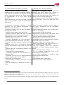
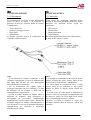
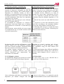
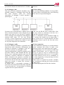
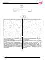
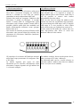
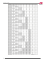
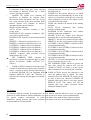
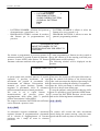
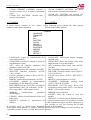
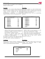
ENGLISH
Instruction manual
Telecamere PTZ dome 10x
TVT77DI - TVT77DE
Mi3176
Leggere attentamente questo manuale prima dell’installazione e conservare per future consultazioni
Read carefully before installing and keep as future reference
ITALIANO
Manuale di istruzioni
TVT77DI – TVT77DE
1. DATI GENERALI
1. GENERAL DATA
1.1 Avvertenze e precauzioni
1.1 Warnings and precautions
ATTENZIONE - WARNING
RISCHIO DI SHOCK ELETTRICO NON APRIRE!
RISK OF ELECTRIC SHOCK – DO NOT OPEN!
ATTENZIONE: PER RIDURRE IL RISCHIO DI SHOCK ELETTRICO, NON RIMUOVERE IL
COPERCHIO. ALL’INTERNO NON CI SONO COMPONENTI RIPARABILI DALL’UTENTE.
RIVOLGERSI AL PERSONALE AUTORIZZATO.
WARNING: TO REDUCE THERISK OF ELECTRIC SHOCK, DO NOT REMOVE THE COVER.
THERE ARE NO USER SERVICEABLE PARTS INSIDE. PLEASE CONTACT TRAINED PERSONNEL.
Cambiamenti o modifiche non espressamente
approvate dal costruttore possono limitare il diritto
di utilizzo dell’apparato da parte dell’utente.
Queste indicazioni possono essere posizionate nella
parte inferiore o posteriore del prodotto e sono atte
a specificare che:
Changes or modification not expressly approved by
the manufacturer can void the warranty of the
product.
The following signs can be placed on the bottom or
on the rear part of the product and means that:
La folgore terminante con una freccia
all’interno di un triangolo equilatero indica
all’utente la presenza di tensioni non
isolate pericolose all’interno del prodotto
stesso che potrebbero rivelarsi di intensità
sufficiente a provocare uno shock elettrico
per le persone.
Il punto esclamativo all’interno di un
triangolo equilatero sta ad indicare
all’utente l’esistenza di un’istruzione
riguardante una funzione o una modalità di
manutenzione
all’interno
della
documentazione che accompagna il
prodotto.
The lighting ended by an arrow inside a triangle
means that there are dangerous voltages inside
the product that could be strong enough to create
electrical shock to people.
The exclamation mark inside a triangle asks to
the user to a specific instruction about A function
or a particular maintenance mode to be checked
on the user manual or documents included with
the product.
ATTENZIONE: PER PREVENIRE IL RISCHIO DI FOLGORAZIONE O INCENDIO,
NON ESPORRE L’APPARATO ALL’ESTERNO IN CODIZIONI DI PIOGGIA O FORTE UMIDITA’.
WARNING: TO PREVENT THE RISK OF ELECTRIC SHOCK OR FIRE, DO NOT EXPOSE THE
APPARATUS TO RAIN OR HIGH HUMIDITY WITHOUT PROTECTION.
Attenzione: l’installazione deve essere Warning: the installation must be done
effettuata da personale qualificato in by trained personnel and according to
accordo con quanto stabilito dalle norme local rules.
nazionali.
Questo prodotto è stato testato e risultato conforme per la marcatura CE.
This product has been tested and complies to rules for CE marking.
2
TVT77DI – TVT77DE
AVVERTENZE PER L’INSTALLATORE
Si raccomanda di attenersi alle normative vigenti sulla
realizzazione degli impianti elettrici e dei sistemi di
sicurezza, oltre che ad ogni eventuale indicazione del
costruttore
o
del
fornitore
riportate
nella
documentazione tecnica fornita insieme ai prodotti.
Si raccomanda inoltre di provvedere ad un’accurata
protezione all’ingresso di acqua o umidità all'interno
della telecamera soprattutto se il contatto tra la base
della staffa e la superficie di installazione non è
consente un'adesione perfetta. In questi casi si
raccomanda di provvedere un'adeguata stagnatura delle
parti.
Questo manuale va consegnato all’utilizzatore
facendone prendere visione della modalità di uso e
manutenzione oltre che come referenza per future
consultazioni.
NOTES FOR THE INSTALLER
It is required to follow local rules about electrical and
security systems building. Moreover it is recommended
to follow all further information provided by the
manufacturer or by the distributor on the technical
documents included with the products.
Provide a suitable protection against entering of water
and humidity inside the camera. If the contact between
the bracket's basement and the installation surface does
not allows a perfect adherence, the camera protection
could be affected. In these cases a suitable seal on both
parts must be done in place.
This manual must be delivered to the final user
explaining the operating mode, care and maintenance
requirements and must be kept for future reference.
AVVERTENZE PER L’UTILIZZATORE
Verificare periodicamente e scrupolosamente che la
funzionalità dell’apparato sia conforme a quella prevista
provvedendo al controllo delle immagini ed alla verifica
della funzionalità delle parti soggette ad usura. La
manutenzione periodica dell’impianto va affidata a
personale specializzato in possesso dei requisiti tecnici
adeguati. Contattare il proprio installatore di fiducia
anche per la verifica dell’adeguatezza dell’impianto al
mutare delle condizioni operative (es. aggiunta di nuove
telecamere, loro nuovo posizionamento, ecc...).
Questo dispositivo è stato disegnato, prodotto e
collaudato con la massima cura, adottando procedure di
controllo di qualità in conformità alle normative vigenti,
pertanto la piena rispondenza delle caratteristiche
funzionali è conseguita solo nel caso di un utilizzo
limitato alla funzione per la quale esso è stato realizzato
e nella rispondenza alle indicazioni di manutenzione
riportate sopra.
NOTES FOR THE USER
It is recommended to check periodically and carefully
that the functionality of the apparatus is still compliant
to the requirements, providing for the pictures and the
working conditions of all the parts under wear. The
periodical maintenance must be done by trained
personnel.
Contact your installer even to check the fitness of the
whole system when the surveillance needs change (i.e.
new cameras adding, position changing, …).
This device has been designed, manufactured and tested
with the maximum care and attention, adopting all the
quality procedures required by actual rules. The
technical specifications and features can be satisfied
only if the device is used according to the function to
which it has been manufactured and according to the
maintenance requirements described above.
AVVERTENZE PER LO SMALTIMENTO
Questo prodotto contiene componenti elettronici
altamente nocivi se dispersi nell’ambiente. Si
raccomanda di fare riferimento alle disposizioni
comunali per il corretto smaltimento dei prodotti
elettronici.
NOTES FOR DISPOSAL
This device includes electronic components highly
dangerous for the environment. It is required to take
care of it and to dispose it at the end of its life according
to the local rules for environment protection.
3
TVT77DI – TVT77DE
1.2 Importanti note per la sicurezza e l’utilizzo 1.2 Important notes for safety and use
Si raccomanda di leggere attentamente questo Please read carefully this manual before installing
manuale
interamente
prima
di
iniziare and using the product, especially the notes and
l’installazione e l’utilizzo del prodotto, in warnings in bold type.
particolare le note e le indicazioni riportate in
grassetto.
1. Non esporre la telecamera all'umidità.
La telecamera è stata progettata per l'uso in interni
(TVT77DI). Nel caso in cui la telecamera rimanga
esposta all'umidità o alla pioggia, spegnerla
immediatamente e richiedere l'intervento di
personale specializzato.
Nel caso in cui sia rimasta dell’umidità all’interno
della telecamera durante l’installazione, è possibile
che forti escursioni termiche ne provochino la
condensa sull’ottica del modulo video. Si
raccomanda di procedere con la massima cura
durante la sua rimozione o contattare il servizio di
assistenza tecnica autorizzato.
La telecamera (TVT77DE) è dotata di guarnizioni e
sistemi di chiusura stagni che garantiscono un
grado di protezione IP66. Tuttavia, sarà cura
dell’installatore verificare e provvedere ad
un’accurata protezione all’acqua ed all’umidità
in corrispondenza delle aperture per il passaggio
di cavi e nella parte posteriore della staffa sia
nel caso di installazione a muro che
nell’istallazione con adattatori da palo o ad
angolo.
2. Non installare questa telecamera sotto sopra.
Questa telecamera è stata progettata per essere
fissata a soffitto o a muro con appositi adattatori.
Installazioni in modalità differenti (ad esempio
appoggiata
al
suolo)
possono
causare
malfunzionamenti.
3. Non tentare di smontare la telecamera da soli.
Per evitare il rischio di scosse elettriche, non
rimuovere alcuna vite o alcun coperchio dalla
telecamera. All'interno non ci sono parti riparabili
dall'utente. Nel caso sia necessario riparare il
prodotto, richiedere l'intervento di personale
specializzato.
4. Evitare di puntare la telecamera direttamente
verso la luce del sole.
Sia che la telecamera sia in funzione che no, si
raccomanda di evitare di lasciare la telecamera
verso la luce diretta del sole o verso oggetti molto
luminosi, come pure puntare il sensore e/o l’ottica
in verso queste fonti. Queste condizioni possono
essere infatti causa di gravi danni al sensore.
4
1. Do not expose the camera to humidity
This camera (TVT77DI) has been designed for
indoor use. In the case of it is exposed to humidity
or rain, switch it off and contact your installer
immediately.
If some humidity is left inside the camera during
the installation, it is possible that high temperature
ranges cause to condense it on the lens surface.
Please use maximum care when removing this
humidity or contact service personnel.
The camera (TVT77DE) has sealing systems to
guarantee IP66 protection degree against dust and
liquids. Nevertheless, the installer must check
and provide a suitable protection against water
and humidity on all the cable's holes and on the
rear part of the bracket's basement even when it
is installed on wall or on pole / corner.
2. Do not install the camera upside down
This camera has been designed to be ceiling or wall
installed with suitable adapters. Different
installation conditions (like on soil) can cause
malfunctioning.
3. Do not attempt to dismount the camera by
yourself
To avoid the risk of electric shock, do not remove
any screw or cover by the product. There are no
user serviceable parts inside. In case it is required
to repair the product please contact trained
personnel.
4. Avoid to shoot direct sunlight with the camera
Even the camera is on or off, avoid to leave it to
direct sunlight or near extreme bright objects.
Even to shoot the sun with the sensor or the lens is
very dangerous and it can cause serious damage to
the CCD sensor.
TVT77DI – TVT77DE
5. Non impiegare solventi o detergenti forti sul
prodotto.
Nel caso sia necessario pulire la telecamera
utilizzare semplicemente un panno soffice ed
asciutto. Se risulta difficile rimuovere dello sporco,
utilizzare un detergente non aggressivo ed agire
gentilmente.
6. Maneggiare la telecamera con cura.
Prestare particolare attenzione quando si maneggia
la telecamera. Evitare urti, vibrazioni... La
telecamera può risultare danneggiata nel caso in cui
venga maneggiata o posizionata in modo
improprio.
7. Prima dell'installazione verificare le
condizioni
di
temperatura,
umidità
e
alimentazione.
Utilizzare la telecamera in condizioni dove la
temperatura è compresa tra 0°C e +40°C e l'umidità
è inferiore a 90%. La corretta tensione di
alimentazione è di 12Vcc 1A.
8. Non utilizzare la telecamera nelle seguenti
condizioni. Sull'ottica si può formare condensa
se la telecamera è utilizzata nelle seguenti
condizioni:
− Elevata escursione termica a causa della
repentina accensione/spegnimento di un sistema di
condizionamento d'aria.
− Elevata escursione termica a causa di frequenti
aperture di porte/finestre con conseguenti forti
correnti d'aria.
− Ambienti dove i vetri si appannano.
− Ambienti saturi di fumo di sigarette o polvere.
Se l'ottica forma della condensa, rimuovere la
cupola e asciugare tutte le superfici che presentano
segni di umidità con un panno soffice.
9. Parti soggette ad usura.
Parti meccaniche quali motori Pan/Tilt e motori
per ottiche ed iride, ventole di raffreddamento,
cinghie, contatti rotanti… sono soggette ad
usura e quindi a degradarsi con l'utilizzo.
Queste parti non sono coperte dalla garanzia.
Questa telecamera non è idonea ad eseguire
funzioni di ronda automatica in modo prolungato e
continuativo, conseguentemente, al fine di limitare
il più possibile il deterioramento delle parti
meccaniche più sollecitate, si consiglia di attivare
queste funzioni solo quando strettamente
necessario. Per la sostituzione e la manutenzione di
queste parti, rivolgersi a personale tecnico
qualificato.
5. Do not use solvents or heavy cleaners on the
product's surface.
In the case it is required to clean the camera's
surface, gently use a clean and soft cloth. If it is
required to clean the camera's surface or dome
cover, use a neutral cleaner and operate gently.
6. Handle the camera with care
Take particular care when handle the camera. It is
recommended to avoid impacts, vibrations... The
camera can be damaged when handled without
suitable care or left in a wrong position.
7. Before installing the product check the
temperature, humidity and power supply
conditions.
Use the camera only when the environment
conditions are between 0°C and +40°C and
humidity below 90%. The right power supply of
this camera is 12Vdc 1A.
8. Do not use the camera in the following
conditions. On the lens surface can condensate
humidity if the camera is used in the following
conditions:
− Extreme temperature range due to air
conditioning power on or off.
− Extreme temperature range due to frequent door
or windows opening and strong air current.
− Environments where windows musts up.
− Environments full of smoke or dust.
If the lens mists up, remove the dome cover and
gently clean all the surfaces where there is
humidity using a soft cloth.
9. Parts needing periodical service.
Some parts like Pan/Tilt motors, motors for lens
and iris, fans, belts and slip contacts are subject
to wear, then it can be required to be changed
during the camera's lifetime. These parts are not
covered by product’s warranty.
This camera is not suitable for continuous
automatic surveillance patrols, then to avoid as
more as possible the deterioration of the more
stressed mechanical parts, it is advised to activate
these functions only when strictly required.
Please refer to technical service for changing the
required parts.
5
TVT77DI – TVT77DE
1.3 Caratteristiche principali e specifiche
1.3 Main features and specifications
Questa telecamera è dotata di un meccanismo di
brandeggio che le consente la completa rotazione a
360° sul piano orizzontale e 90° sul piano verticale.
Inoltre, la particolare ottica di cui è dotata consente
un ingrandimento di 10 volte degli oggetti
inquadrati.
Il suo controllo può avvenire sia tramite consolle
dedicate (tipo SK-AR11 o AT8) che tramite DVR o
video server1.
This camera is equipped with a PAN/TILT
mechanics that allows endless 360° rotation on
horizontal plane and 90° on the vertical plane.
Moreover, the lens built-in the video module can
magnify up to 10 times the shot objects.
The camera can be easily controlled by keyboards
(such as SK-AR11 or AT8) or DVR and video
servers1.
- Dimensioni estremamente compatte e design
gradevole per una perfetta integrazione con
l’ambiente di installazione.
- Rotazione continua a 360° sul piano orizzontale e
90° sul piano verticale.
- Controllo remoto tramite linea dati RS-485.
- Supporto protocolli Pelco-P/D, baud rate 2400,
4800, 9600 bps con riconoscimento automatico.
- Disponibilità di varie consolle di comando.
- Zoom massimo 10x (ottico).
- Funzione Day&Night con ICR meccanico e
sistema di illuminazione ad IR (solo TVT77DI).
- Velocità massima di rotazione massima 160°/sec
(PAN).
- Funzione Smart Zoom : la velocità di rotazione
massima inversamente proporzionale al livello di
zoom.
- Funzione auto-flip: sorveglianza continua a 180°
sul piano verticale.
- 71 posizioni Pre-set programmabili.
- 4 traiettorie (pattern) di 100 movimenti e 1
scansione cruise.
- Tecnologia vector drive per il raggiungimento di
posizioni il minor numero di movimenti.
- Menù OSD di configurazione.
- Visualizzazione a schermo del livello di zoom
utilizzato.
- Staffa di montaggio per installazione a muro o a
soffitto.
- Design extremely compact and nice shape to
allow perfect integration with the surrounding
environment.
- Endless continuous rotation (360°) on PAN plane
and 90° on TILT plane.
- Remote control via RS-485 data line.
- Supports Pelco P/D protocols, 2400 / 4800 / 9600
bps baud rate with automatic recognition.
- Various controllers and keyboards available.
- Magnification zoom (max 10x optical).
- Day&Night function with mechanical ICR and IR
light system (only on TVT77DI).
- Maximum rotation speed 160°/sec (PAN).
- Smart Zoom function: the rotation speed is in
inverse proportion to the zoom value.
- Auto Flip capability: allows 180° continuous
surveillance to objects passing through vertical
position.
- Up to 71 Pre-set positions storage.
- Up to 4 patterns (composed of up to 100
movements) and 1 cruise scan.
- Vector Drive technology to reach the final
position using the shortest path.
- OSD menu.
- Zoom magnification value display.
- Brackets for wall or ceiling installation.
1
L'effettiva disponibilità delle funzioni qui elencate, nell'attivazione tramite dispositivi quali DVR o video server, può essere
limitata a causa della non completa implementazione di tutte le funzioni previste dai protocolli di comunicazione nel
dispositivo utilizzato per il controllo stesso.
1
The availability of all the functions here above described, when the camera is controlled by devices such as DVR or video
servers, can be limited due to a not complete implementation of all the protocol's functions into the device used to control the
camera.
6
TVT77DI – TVT77DE
2. INSTALLAZIONE
2. INSTALLATION
2.1 Collegamenti
2.1 Connection
Si raccomanda di verificare lo stato dell’imballo
prima di aprire lo stesso e di verificare la
presenza di tutti gli accessori prima di iniziare
l’installazione:
− Telecamera PTZ
− Staffa per fissaggio a muro
− Base staffa
− Alimentatore
Il disegno seguente mostra le connessioni da
effettuare sulla telecamera:
Please check the packaging condition before
opening it, and check that all the items here below
described are included before begin the
installation:
− PTZ camera
− Wall bracket
− Bracket basement
− Power adaptor
The following diagram shows the connections to
be made at the camera’s cables.
Note:
- Si raccomanda di prestare attenzione a non
collegare erroneamente la linea di alimentazione
alla linea dati RS-485 per non danneggiare
irreparabilmente la telecamera.
- Per la trasmissione del segnale video è
necessario impiegare un cavo coassiale a 75 ohm
da collegare ad un monitor o DVR per la
visualizzazione / registrazione.
- Al fine di evitare disturbi al segnale video o
difficoltà di controllo della telecamera si
raccomanda di provvedere canalizzazioni
distanziate tra i cavi di segnale video e RS-485 da
eventuali sorgenti di disturbi elettromagnetici o
cavi di potenza. Viceversa, la distanza massima di
comunicazione tra controller e telecamera
potrebbe essere ridotta.
Notes:
- It is strongly recommended to be aware to do not
connect wrongly the power supply cables to the
RS-485 line to avoid camera’s malfunction.
- For video signal it is required to use a 75 ohm
coaxial cable to be connected to the system
monitor or DVR to display and/or record the
pictures.
- To avoid noises to video signal or difficulties in
camera’s control it is strongly recommended to run
the camera’s cables far from high power mains
lines or electromagnetic noise’s sources.
Otherwise, it could be required to reduce the
maximum distance allowed between camera and
controller.
7
TVT77DI – TVT77DE
2.2 Distanze massime e terminazione
2.2 Maximum distances and termination
In conformità allo standard RS-485, il numero
massimo di dispositivi collegabili ala linea dati
non deve essere superiore alle 32 unità (incluso il
dispositivo di controllo). Inoltre, al fine di
garantire la corretta trasmissione dei dati per tutta
la lunghezza della linea, si deve provvedere alla
corretta terminazione della linea con impedenza
caratteristica di 120 ohm.
Il cablaggio della linea dati può essere effettuato
con cavo twistato AWG24.
Si raccomanda di configurare la velocità di
trasmissione sulla linea (baud rate) in funzione
della distanza tra il controller e la telecamera più
lontana.
Indicativamente, questa tabella può essere tenuta
in considerazione per la corretta selezione della
velocità di trasmissione:
According to RS-485 standard, the maximum
number of devices to be connected to the same
data line should not be higher than 32 (including
the controller device). Moreover, in order to
guarantee the correct data’s transmission, all line
over, it is required to provide the correct line’s
termination using the standard impedance of 120
ohm.
The RS-485 line can be run with AWG24 twisted
cable.
It is required to set the data transmission speed
(baud rate) according to the maximum distance
between the camera and the controller device.
The following table can give a rough idea about
the transmission speed selection considering the
distances between devices.
Baud rate
Distanza massima
Maximum distance
2400 bps
1200m
4800 bps
800m
9600 bps
600m
In funzione della topologia dell'impianto e delle
distanze relative tra i vari dispositivi collegati,
può essere richiesto di adattare l'impedenza della
linea con resistori da 120 ohm (non inclusi).
Gli schemi seguenti mostrano una serie di
modalità di cablaggio differenti nelle quali
ciascun dispositivo può rappresentare una
telecamera o un controller.
According to system’s topology and devices’
relative distances, it can be necessary to adapt
line’s impedance using 120 ohm resistors (not
included).
The following diagrams show different installation
situations and possible cabling ways: each device
showed in these diagrams can be a camera or a
controller.
2.2.1 Cablaggio a cascata
2.2.1 Daisy chain
La modalità di cablaggio più corretta per la linea The most correct way to run a RS-458 line is
RS-485 è quella mostrata nella figura seguente:
showed in the following picture:
Come evidenziato nella figura è necessario che il As shown on the picture, it is required to put the
dispositivo più lontano collegato alla linea 120 ohm termination resistor on the farthest device
8
TVT77DI – TVT77DE
presenti una chiusura di terminazione di 120ohm.
connected.
2.2.2 Cablaggio a bus
Dato che in alcune condizioni installative non è
possibile effettuare il cablaggio della linea RS485 come mostrato sopra, uno schema
equivalente di cablaggio è quello mostrato in
questa figura:
2.2.2 Bus cabling
Since in some installing condition it is not possible
to run the cables as described above, the following
picture shows an equivalent diagram:
In questo caso la linea RS-485 è cablata come un
bus e ciascuna telecamera viene collegata ad essa
tramite una tratta di cavo derivata in parallelo.
Esiste comunque una limitazione sulla lunghezza
massima delle tratte “D” che non devono
eccedere i 7 metri. In questo caso è necessario che
la terminazione di chiusura da 120ohm sia posta
sia sul primo dispositivo che sull'ultimo.
In this case the RS-485 line is cabled like a bus
and every camera is connected to the bus via a
stretch line connected in paralel.
There is a limitation on the maximum length of
“D” sections that should not be longer than 7
meters. In this case it is required that the 120 ohm
termination resistor is put on the first and on the
last devices.
2.2.3 Cablaggio a stella
In alcune situazioni installative è possibile che la
disposizione delle telecamere dell'impianto non
permetta di effettuare il cablaggio a bus, ma è
necessario realizzare un cablaggio a stella.
Questa configurazione, seppur in contrasto con le
specifiche richieste dallo standard RS-485, può
ancora essere realizzata tenendo conto però che
potrebbero verificarsi difficoltà di controllo di
alcune telecamere (ad esempio è possibile che
queste non rispondano all'invio di comandi, o che
si muovano solo ad intervalli, oppure ancora che
dopo aver iniziato a ruotare non ricevano il
comando di stop).
In questo casi si raccomanda comunque di
provvedere alla terminazione della linea seguendo
i criteri descritti per i casi precedenti. Lo schema
seguente descrive questa situazione:
2.2.3 Star connection
In some installation situations it is possible that the
cameras’ positions don’t allow to make a bus
connection, while a star connection can be made.
This configuration, even if in contrast with RS-485
standard specification, can be made as well.
However it must be kept in consideration that
controlling difficulties can occur (i.e. it is possible
that some cameras do not act to commands, or
move only temporarily, or keep moving even after
stop command is sent).
In these cases it is required to provide a suitable
line’s termination following the criteria described
on above cases.
The following diagram describes the situation:
9
TVT77DI – TVT77DE
Come si nota, in questo caso le resistenze di
terminazione sono state introdotte sia sul
dispositivo più vicino al centro della stella che su
quello più lontano.
In casi particolari potrebbe essere necessaria
l'introduzione di un distributore di segnale da
posizionare al centro della stella: questo
dispositivo fa in modo che ciascuna linea sia
correttamente collegata al resto dell'impianto e,
per quanto riguarda la terminazione dei dispositivi
si possa fare riferimento alle tipologie installative
a bus descritte nei paragrafi precedenti.
Lo stesso dispositivo può essere utile anche nel
caso di impianti con più di 31 telecamere.
Si raccomanda di rispettare queste specifiche al
fine di garantire il corretto funzionamento dei
dispositivi collegati alla linea dati.
As showed, in this case the resistors are put on
devices farthest and nearest to the star centre.
In some particular conditions it could be necessary
to use a signal distributor on the star centre: this
device allows that every line is rightly connected
to the rest of the system and, regarding the
device’s termination, the daisy chain or bus
cabling types described on the previous paragraphs
can be applied again.
The same signal distributor can be used also on
systems where it is required to install more than 31
cameras.
It is strongly recommended to respect these
specifications to guarantee the right camera’s and
device’s working conditions.
2.3 Selezione Protocollo e Baudrate
2.3 Protocol and baudrate selection
Queste telecamere sono compatibili con i
protocolli Pelco P e Pelco D.
I valori di baud rate supportati sono: 2400, 4800,
9600 bps.
La telecamera rileva automaticamente il
protocollo ed il baud rate di trasmissione utilizzati
dalla consolle o dal DVR durante il suo
funzionamento, di conseguenza non è necessaria
alcuna programmazione di questi parametri di
comunicazione.
These cameras are compatible with Pelco D and
Pelco P protocols.
The supported baud rates are: 2400, 4800, 9600
bps.
The
camera
detects
automatically
the
communication protocol and baud rate used by
the DVR or controller keyboard during its
working. Then it is not required to set any of
these communication parameters during the
installation.
10
TVT77DI – TVT77DE
2.4 Selezione indirizzo
2.4 Address selection
Nel caso di utilizzo di più telecamere sulla stessa
linea dati è necessario assegnare un indirizzo
univoco a ciascuna di esse (ID) per poterle
comandare in modo indipendente dalle altre.
Esistono due modi per assegnare l'indirizzo alla
telecamera: il primo via hardware, il secondo
tramite il menù OSD di configurazione della
telecamera (soft). Sempre tramite il menù OSD è
possibile stabilire quale delle due modalità sarà
quella effettivamente utilizzata (come spiegato
nella sezione 4.2).
Nel circuito di controllo presente all'interno della
telecamera sono presenti alcuni dip-switches che
consentono di selezionare l'indirizzo (hardware)
della telecamera.
In the case of many cameras are connected at the
same RS-485 line, it is required to assign an
unique address (ID) to each of them, in this way it
will be possible to control each camera
independently from the others.
There are two ways to assign the address to the
cameras: the first one via hardware (dip-switches),
the second using the OSD menu (soft). Using the
OSD menu it is even possible to select which
mode will be active (as explained on section 4.2).
On the control PCB inside the camera there are
some dip-switches that allow to select the
hardware address for the camera.
Gli switch per la selezione dell’indirizzo mostrati
nella figura sopra permettono di configurare fino
a 255 unità.
La tabella seguente può essere un utile
riferimento per la selezione dell’indirizzo della
telecamera (vengono riportati solo gli indirizzi da
1 a 64 come esempio).
The address switches, shown on the picture above,
allow to set up to 255 units / addresses.
The following table can be a useful reference to
select the camera’s address (here there are address
from 1 to 64, the rest is omitted).
11
TVT77DI – TVT77DE
12
TVT77DI – TVT77DE
3. Funzionamento
3. Operating mode
A causa della differente modalità di integrazione
dei protocolli di comunicazione in telecamere e
dispositivi di controllo quali consolle e DVR, è
possibile che non tutte le funzioni sopportate dalla
telecamera siano effettivamente attivabili. Nella
descrizione che segue si fa riferimento alla
consolle AT8, per le stesse ragioni spiegate sopra
è possibile che, utilizzando altre combinazioni di
dispositivi, la modalità di funzionamento o
attivazione di alcune funzioni sia differente.
Due to different communication protocol's
integrating ways between different cameras and
control devices such as DVR or keyboards, it can
be possible that some of the functions described
here below are not usable. On the following
description AT8 keyboard will be taken as
reference, due to the reasons described above it is
possible that using different device’s combination,
the working way of some functions are different.
3.1. Inizializzazione
3.1 Set - up
All'accensione della telecamera questa effettuerà
una rotazione di inizializzazione automatica
durante la quale verranno eseguiti movimenti in
orizzontale ed in verticale. Al termine di questa
fase sarà possibile muovere liberamente la
telecamera utilizzando il joystick.
La telecamera si muoverà coerentemente ai
movimenti operati attraverso il joystick
(destra/sinistra, alto/basso). Per azionare lo zoom
è possibile ruotare il joystick sul proprio asse: la
rotazione in senso orario provocherà un
ingrandimento dell'area inquadrata (zoom in), la
rotazione in senso antiorario provocherà un
allargamento dell'area inquadrata (zoom out).
As the camera power is on, it will perform the boot
sequence during which it will run on horizontal
and vertical movements. At the end of this
sequence it will be possible to control the camera
using the joystick.
The camera will move according to the joystick
movements (right/left, up/down). To activate the
optical zoom it is possible to rotate the joystick on
its own axis: the clockwise rotation will operate
the magnification of the shot area (zoom in), while
the counter clockwise rotation will operate the
zoom out.
3.2 Memorizzazione Pre-set
3.2 Pre-set storing
Per memorizzare una posizione Pre-set (definita
da tutte le coordinate PAN, TILT e ZOOM), e
poterla richiamare successivamente in modo
manuale o automatico, muovere dapprima la
telecamera utilizzando il joystick fino ad ottenere
l’inquadratura
desiderata,
successivamente
premere i tasti nella sequenza mostrata sotto:
To store a Pre-set position (according to all PAN,
TILT and ZOOM coordinates), and to call it
manually or automatically, move firstly the camera
up to the desired position and then press the button
sequence on the keyboard as here below:
[SET] + n° [1-255] + [PRE]
[SET] + n° [1-255] + [PRE]
3.3 Richiamo Pre-set
3.3 Pre-set call
E' possibile richiamare istantaneamente ciascuna It is possible to call each Pre-set position stored
delle posizioni memorizzate precedentemente con before using the following button sequence:
la seguente combinazione di tasti:
n° [1-255] + [PRE]
n° [1-255] + [PRE]
13
TVT77DI – TVT77DE
3.4 Funzione Scan
3.4 Scan function
Attivando la funzione SCAN, la telecamera
effettuerà la rotazione completa a 360° sul piano
orizzontale. L'esecuzione della funzione SCAN
prevede delle brevi soste circa ad ogni 110° durante
la rotazione.
Per attivare la funzione SCAN operare come segue:
With the SCAN function the camera will perform a
complete endless 360° rotation.
During the SCAN function the camera will
randomly for a while.
To activate the SCAN function press the following
buttons:
[SET] + [1] + SCAN
[SET] + [1] + SCAN
3.5 Funzione Pattern
3.5 Pattern function
La funzione PATTERN permette di memorizzare
un percorso definito dall'utente, per eseguirlo in
modo identico continuativamente.
Questa telecamera permette di memorizzare fino a 4
percorsi PATTERN costituiti ciascuno da un
massimo di 100 movimenti nelle coordinate PAN,
TILT e ZOOM.
Per attivare l'esecuzione di una delle funzioni
PATTERN è necessario utilizzare questa
combinazione di tasti:
The PATTERN function allows to record an
arbitrary path according to the user’s surveillance
needs and to repeat it continuously.
The camera allows to store up to 4 paths and each
path can be made of up to 100 movements on PAN,
TILT and ZOOM coordinates.
To activate one of the recorded PATTERN it is
required to use the following button combination:
[1-4] + [PAT]
[1-4] + [PAT]
La memorizzazione dei PATTERN avviene tramite To set the PATTERN sequence use the OSD option
menù OSD come spiegato nella sezione 4.4.
as described on section 4.4.
4. Menù OSD
4. OSD Menu
Questa telecamera è dotata di un menù OSD di
configurazione che permette di regolare i parametri
video di ripresa, ma anche di attivare / disattivare
alcune funzioni particolari.
All'accensione della telecamera, e durante la fase di
inizializzazione, verranno mostrate a schermo
alcune informazioni quali:
This camera has a configuration OSD menu that
allows to set up all the video parameters and to
activate or de-activate some particular functions.
When the camera is turn on, and during the booth
sequence, some information will be displayed on
the screen, such as:
PTOL: AUTO
COMM: AUTO
ADDR: 1
In particolare, al fine di attivare la visualizzazione
del menù OSD, prestare attenzione a che l'indirizzo
visualizzato dal display della tastiera sia quello
relativo alla telecamera desiderata.
Per attivare la visualizzazione del menù OSD è
necessario che la telecamera sia in modalità di
funzionamento manuale e che cioè non siano in
esecuzione alcuna delle funzioni di ronda
14
PTOL: AUTO
COMM: AUTO
ADDR: 1
In particular, in order to activate this OSD menu
display, pay attention that the address displayed on
the keyboard LCD display is the same of that one
assigned to the camera to be controlled.
To activate the OSD menu's display, the camera
must be on manual control mode, and also no any
automatic patrol function are in execution.
However, it is always possible to move the joystick
to come back to manual control.
TVT77DI – TVT77DE
automatica. Altrimenti, per passare alla modalità di To display the OSD menu press the following
controllo manuale, è sufficiente muovere il joystick buttons:
in qualunque direzione.
Per attivare il menù OSD premere i seguenti tasti:
[95] + [PRE]
[95] + [PRE]
MAIN MENU
→ SYSTEM INFORMATION
ADRESS SETTING
MOTION
PATTERNS
CAMERA
CRUISE SETTING
DISPLAY SETTING
IR SETTING
RESTORE FACTORY DEFAULT
REBOOT SYSTEM
EXIT
Muovere il joystick nelle 4 direzioni per spostare il
cursore all'interno del menù OSD: il movimento del
joystick verso destra ha valore di selezione di
un'opzione o permette di accedere ad un eventuale
sotto menù.
Lo stesso effetto lo si ottiene premendo il tasto
OPEN.
Una volta selezionata un'opzione è possibile
scorrere i valori assegnabili al parametro muovendo
il joystick verso l'alto o verso il basso.
Tramite il tasto CLOSE è possibile uscire
completamente dal menù.
Move the joystick on the 4 directions to navigate
into the OSD menu: when the joystick is moved to
right it will have the same effect of selecting an
option or to go to the following menu page.
The same effect can be reached even pressing the
OPEN button.
Once an option is selected, it is possible to change
its value moving the joystick up or down.
Using the CLOSE button it is possible to exit the
menu.
4.1 Informazioni di sistema
4.1 System information
L'opzione SYSTEM INFORMATION consente di
accedere alla finestra che visualizza le informazioni
tecniche relative alla telecamera (alcuni di questi
valori non possono essere modificati dall'utente):
The SYSTEM INFORMATION option allows to
display the window with technical information
about the camera (some of these parameters cannot
be changed by the user):
SYSTEM INFORMATION
→ COM
9600, N, 8, 1
ADDRESS
1
SOFTWARE VERSION
V5.2
BACK
EXIT
15
TVT77DI – TVT77DE
−
−
−
−
−
COM: visualizza i dettagli di comunicazione
correntemente utilizzati dalla telecamera
(baudrate, parità, bit dati e stop bit):
ADDRESS:
visualizza
l'indirizzo
correntemente assegnato alla telecamera (0255).
SOFTWARE VERSION: versione del
software interno della telecamera.
BACK: torna al menù precedente.
EXIT: esce completamente dal menù.
4.2 Selezione indirizzo
−
−
−
−
−
COM: displays the communication parameters
currently set on the camera (baudrate, parity,
data bits and stop bit).
ADDRESS: displays the address currently set
to the camera (0-255).
SOFTWARE VERSION: displays the camera's
software version.
BACK: turns to previous menu page.
EXIT: closes the OSD menu.
4.2 Address selection
Il menù di selezione dell'indirizzo viene mostrato The address selection menu is shown in the picture
nella figura qui sotto:
here below:
ADDR SETTING
→ ADDR TYPE
ADDR SOFT
ADDR HARD
BACK
EXIT
−
ADDR TYPE: questa opzione consente di
selezionare la modalità di assegnazione
dell'indirizzo HARD o SOFT. Con la modalità
HARD l'indirizzo viene assegnato tramite i dipswitches presenti all'interno della telecamera
(come mostrato nelle figure della sezione 2.4).
Impostando la questa voce sulla modalità
SOFT invece, l'assegnazione dell'indirizzo
tramite dip-switches verrà ignorata e l'indirizzo
della telecamera potrà essere specificato tramite
l'opzione seguente2.
− ADDR SOFT: consente di specificare
l'indirizzo da assegnare alla telecamera nel caso
di modalità di funzionamento “SOFT”.
− ADDR HARD: (voce non modificabile da
menù) visualizza l'indirizzo correntemente
assegnato alla telecamera tramite i dipswitches.
−
4.3 Motion
4.3 Motion
HARD
255
1
ADDR TYPE: this option allows to set the
address selection mode between HARD or
SOFT. Using the HARD mode, the camera's
address will be assigned using the dip-switches
inside the camera body (as shown on section
2.4).
While selecting the SOFT mode on this option,
the dip-switches positions will be ignored and
the camera's address assignment can be made
using the next option2.
− ADDR SOFT: this option allows to specify the
camera's address when the SOFT mode is
selected.
− Use the joystick to change the value of the
camera's address.
− ADDR HARD: (not changeable via OSD
menu) this option just shows the hardware
address currently assigned to the camera by its
dip-switches.
La finestra Motion contiene alcune opzioni di The Motion window contains some programming
programmazione relative all'esecuzione di funzioni options relatively to automatic patrol functions
di ronda automatiche in caso di perdita di execution in the cases of power loss or after a
2
2
Si raccomanda di riavviare la telecamera dopo aver modificato l'opzione da HARD a SOFT o viceversa.
It is required to re-boot the camera after HARD/SOFT option is changed.
16
TVT77DI – TVT77DE
alimentazione o dopo un determinato periodo di certain period of no activity (Park Action).
inattività.
MOTION
→ FRAME SCAN
POWER UP
PARK TIME
PARK ACTION
BACK
EXIT
NONE
15s
NONE
− FRAME SCAN: opzione che consente di − FRAME SCAN: this option allows to enter the
sub-menu devoted to program the Frame Scan
accedere al sotto-menù per la programmazione
function. This function allows to execute an
della funzione Frame Scan. Questa funzione
automatic scan (only on PAN coordinate)
permette di effettuare la scansione automatica
(solo nella coordinata PAN) tra due posizioni
between two positions to be set using the next
predefinite tramite il sotto-menù seguente:
menu page:
FRAME SCAN
→ SET SCAN POSITION
CLEAR FRAME SCAN
FRAME SCAN SPEED
BACK
EXIT
Per stabilire il limite destro e sinistro della
funzione Frame Scan, selezionare l'opzione
“Set
Scan
Position”,
successivamente
posizionare la telecamera in corrispondenza del
primo punto e premere il tasto OPEN,
posizionare poi la telecamera in corrispondenza
del secondo punto e premere nuovamente il
tasto OPEN.
SET FRAME SCAN
LEFT LIMIT POSITION
IRIS OPEN TO CONTINUE
16
To set the left and right Frame Scan limits,
select the “Set Scan Position” option, move the
camera up to the first desired position (left) and
then press OPEN button on the keyboard.
Move the camera to the second point and then
press again the OPEN button to set the second
position (right).
SET FRAME SCAN
RIGHT LIMIT POSITION
IRIS OPEN TO CONTINUE
− CLEAR FRAME SCAN: tramite questa − CLEAR FRAME SCAN: selecting this option
opzione verranno cancellate entrambe le
both left and right positions (Frame Scan limits)
posizioni (limite destro e sinistro) della
will be erased.
funzione Frame Scan.
− FRAME SCAN SPEED: this option alows to
set the execution speed of Frame Scan function:
− FRAME SCAN SPEED: velocità di esecuzione
della funzione Frame Scan: 1-32 (valori più alti
1-32 (higher values mean higher speed).
indicano velocità maggiore).
The Frame Scan function can be activated only
17
TVT77DI – TVT77DE
using the function “Power up” or “Park Action”
La funzione Frame Scan può essere attivata
described below.
solo tramite le funzioni “Power up” e “Park
Action” descritte di seguito.
− POWER UP: this option allows to set which
function must run automatically as soon as the
−
POWER UP: questa voce consente di
camera is powered on and in the case of no any
specificare la funzione da eseguire dopo
other command is received. This option can be
l'accensione della telecamera nel caso in cui
set to the following values:
non venga ricevuto alcun altro comando dalla
NONE: the camera will remain at the starting
tastiera. Questa voce consente di attivare
position.
automaticamente queste funzioni:
AUTO SCAN: continuous 360° endless
NONE: nessuna funzione
rotation (without stops).
AUTO SCAN: rotazione continua a 360°
RANDOM SCAN: continuous 360° endless
(senza soste)
rotation (with stops randomly).
RANDOM SCAN: rotazione continua a 360°
FRAME SCAN: the Frame Scan function,
(con soste in punti casuali)
described above, will be called automatically.
FRAME SCAN: funzione Frame Scan descritta
PRESET 1: the Pre-set 1 position will be called.
sopra
PRESET 8: the Pre-set 8 position will be called.
PRESET 1: richiama la posizione Pre-set 1
PATTERN 1: the PATTERN 1 function will be
PRESET 8: richiama la posizione Pre-set 8
executed automatically.
PATTERN 1: richiama il percorso Pattern 1
PATTERN 2: the PATTERN 2 function will be
PATTERN 2: richiama il percorso Pattern 2
executed automatically.
PATTERN 3: richiama il percorso Pattern 3
PATTERN 3: the PATTERN 3 function will be
PATTERN 4: richiama il percorso Pattern 4
executed automatically.
CRUISE: scansione delle posizioni Pre-set
PATTERN 4: the PATTERN 4 function will be
memorizzate (da 1 a 20)
executed automatically.
−
SET PARKING TIME: consente di
CRUISE: it will scan automatically the stored
specificare il tempo di inattività dopo il quale
Pre-set positions (from 1 to 20).
attivare la funzione “PARK ACTION” (15-
−
250sec.).
−
PARK ACTION: funzione da attivare dopo
il tempo di inattività specificato sopra. Possono
essere eseguite le stesse funzioni descritte per
la funzione POWER UP, con l'aggiunta della
funzione REPEAT LAST che richiama la
funzione attiva prima del passaggio al controllo
manuale.
−
SET PARKING TIME: allows to specify the
time after which the camera will run the
“PARK ACTION” (15-250sec.), in the case no
other command is received from the controller.
PARK ACTION: specify the function to run
once the parking time is ended. The same
functions listed on POWER UP option can be
set also in this case. Moreover POWER UP
function allows here there is one more option:
REPEAT LAST. This option will call the
function that were under execution before
taking the manual control.
4.4 Patterns
4.4 Patterns
La funzione Pattern consente di memorizzare un
percorso di ronda arbitrario definito dall'utente per
poi poterlo eseguire nuovamente in modo
automatico. Questo percorso può essere costituito
da un massimo di 100 movimenti.
The Pattern function allows to store an arbitrary
path by the user and to repeat it automatically.
This path can be made of up to 100 movements.
This camera can store up to 4 different patterns.
18
TVT77DI – TVT77DE
PATTERNS
→ PATTERN NUMBER
1
PROGRAM PATTERN
CLEAR CURRENT PATTERN
CLEAR ALL PATTERNS
BACK
EXIT
− PATTERN NUMBER: selezione del percorso − PATTERN NUMBER: it allows to select the
da memorizzare o cancellare (1-4).
Pattern to be set or erased (1-4).
− PROGRAM PATTERN: consente di accedere − PROGRAM PATTERN: it allows to enter the
alla finestra per la programmazione del
pattern's programming window.
percorso.
PROGRAM PATTERN
MOVE THE CAMERA TO THE
STARTING POSITION “IRIS OPEN” TO
CONTINUE
Per iniziare a programmare il percorso spostare la
telecamera tramite il joystick al punto di partenza e
premere il tasto OPEN sulla tastiera. La finestra
mostrata a schermo cambierà nella seguente:
To start programming a Pattern use the joystick to
move the camera up to the starting point and press
OPEN button on the keyboard.
The following window will be displayed on the
monitor.
STORAGE USED <PCT> 1%
A questo punto sarà possibile muovere il joystick
seguendo il percorso desiderato, ad ogni
movimento del joystick la percentuale verrà
incrementata ad indicare l'occupazione della
memoria per questa funzione. Quando verrà
raggiunta la percentuale 100% la telecamera
tornerà automaticamente al menù precedente.
Nel caso in cui si voglia fermare la
memorizzazione del percorso prima del
raggiungimento della quota 100% è possibile
premere nuovamente il tasto OPEN.
Per eseguire la funzione PATTERN sarà sufficiente
uscire dal menù e premere i tasti:
Then move the joystick to all required directions so
that the camera will follow to the desired path.
After each movement the displayed percentage will
be increased according the memory's occupation.
Once the 100% percentage is achieved the camera
will exit to the previous menu page.
To stop the pattern's setting before achieving 100%
quote it is possible to press again the OPEN button.
To execute the PATTERN function, exit the menu
and use the following button combination:
[1-4] + [PAT]
[1-4] + [PAT]
La telecamera eseguirà esattamente i movimenti The camera will execute the same movements
registrati durante la programmazione rispettando stored during the pattern storing, using the same
sia le velocità di raggiungimento di ciascuna speeds and the same stop time on each positions.
posizione che i tempi di sosta in ciascuna
posizione.
19
TVT77DI – TVT77DE
− CLEAR CURRENT PATTERN: cancella il − CLEAR CURRENT PATTERN: this option
will erase the selected Pattern function.
percorso relativo al n° di pattern selezionato
sopra.
− CLEAR ALL PATTERN: this function will
erase all the recorded patterns into the camera.
− CLEAR ALL PATTERN: cancella tutti i
percorsi memorizzati.
4.5 CAMERA
4.5 CAMERA
Il menù camera contiene le voci relative ai The following menu contains the video options
parametri video della telecamera:
related to the camera module:
CAMERA
LANGUAGE
ZOOM DISP
AGC
BLC
SHUTTER
FOCUS
BRIGHT
COLORSEL
IRCUTMOD
MIRROR
LENINIT
DEFAULT
− LANGUAGE: lingua di visualizzazione del
menù OSD (inglese)
− ZOOM DISP: visualizza a schermo il livello di
ingrandimento (zoom)
− AGC: valore de controllo automatico del
guadagno (AUTO/120-240)
− BLC: compensazione del controluce (ON/OFF)
− SHUTTER: otturatore elettronico (AUTO/
1/50-1/10.000)
− FOCUS: modalità di messa a fuoco (AUTO /
KEYAUTO / MAN)
− BRIGHT: luminosità dell'immagine (20-220)
− COLORSEL: modalità di funzionamento
Day&Night (AUTO/BLACK/COLOR)
− IRCUTMOD (solo per TVT77DI) : modalità di
funzionamento filtro IR removibile AUTO /
ON (sempre B/N) / OFF (sempre colore)
− MIRROR:
visualizzazione
specchiata
dell'immagine
− LENINIT: effettua l'inizializzazione della sola
parte ottica
− DEFAULT: richiama le impostazioni di
fabbrica.
− LANGUAGE: OSD menu display language
(English only).
− ZOOM DISP: allows the display of the zoom
magnification level on the monitor.
− AGC: Automatic Gain Control value (AUTO /
120-240).
− BLC: backlight compensation (ON/OFF).
− SHUTTER: electronic shutter speed (AUTO /
1/50-1/10,000 sec.)
− FOCUS: focus mode (AUTO / KEYAUTO /
MAN)
− BRIGHT: picture brightness (20-220)
− COLORSEL: Day&Night working mode
(AUTO / BLACK /COLOR)
− IRCUTMOD (TVT77DI only): IR-cut filter
removable working mode AUTO / ON (always
B&W) / OFF (always colour)
− MIRROR: mirrored picture
− LENINIT: make the re-boot of only lens
module.
− DEFAULT: it calls the factory default options.
To escape from this menu, it is possible to wait for
a while without moving the joystick, otherwise it is
also possible to exit just pressing the CLOSE
E' possibile uscire da questo menù attendendo button on the keyboard.
alcuni istanti senza muovere il joystick, altrimenti In both cases all the changes will be stored by the
è possibile premere il tasto CLOSE della tastiera camera.
20
TVT77DI – TVT77DE
per uscire subito, in entrambi i casi le modifiche
effettuate verranno salvate.
4.6 Cruise
4.6 Cruise
La funzione Cruise consiste nella chiamata delle
posizioni Pre-set in sequenza. Tramite la funzione
Cruise è possibile memorizzare una sequenza
costituita da un massimo di 20 posizioni
precedentemente memorizzate. Le immagini
seguenti mostrano le finestre di programmazione:
The Cruise function is a call of all the Pre-set
positions in sequence. Using the Cruise function it
is possible to create a patrol sequence of up to 20
Pre-set positions previously set.
The following pictures show the programming
windows:
CRUISE SETTING
→ DWELL TIME (SEC)
PRESET1
PRESET2
PRESET3
PRESET4
PRESET5
PRESET6
PRESET7
PRESET8
PRESET9
PRESET10
CRUISE SETTING
PRESET11
PRESET12
PRESET13
PRESET14
PRESET15
PRESET16
PRESET17
PRESET18
PRESET19
PRESET20
BACK
8
ON
ON
ON
ON
ON
ON
ON
ON
ON
ON
ON
ON
ON
ON
ON
ON
ON
ON
ON
ON
− DWELL TIME: utilizzare questo parametro per
specificare il tempo di sosta (in secondi) in
corrispondenza di ciascuna posizione.
− Lista Pre-set: utilizzare questa lista per
includere / escludere il richiamo delle varie
posizioni Pre-set dalla sequenza.
Per eseguire la sequenza Cruise dalla telecamera,
assegnare il valore “Cruise” alla funzione “Power
up” o “Park Action” descritte nel paragrafo 4.3.
− DWELL TIME: use this parameter to set the
stop time in each position (in seconds).
− Pre-set list: use this list to include or not
include the Pre-set position into the sequence.
To run the Cruise function, set “CRUISE” value to
the “Power up” or “Park Action” functions
described on section 4.3.
4.7 Display
4.7 Display
Questa sezione consente di attivare o disattivare la This section allows to add or remove to the screen
visualizzazione a schermo di alcune informazioni display some information related to camera
relative al posizionamento della telecamera.
positions and movements.
DISPLAY SETUP
→ PRESET LABEL
ZOOM
P/T DEG
BACK
EXIT
ON
ON
ON
21
TVT77DI – TVT77DE
− Preset label: consente la visualizzazione del − Preset label: it allows to display the name and
position of the current Pre-set position.
nome della posizione Pre-set visualizzata
correntemente.
− Zoom: it allows to display the current
magnification level of the lens (optical zoom).
− Zoom: consente la visualizzazione del livello di
ingrandimento dell'ottica (zoom).
− P/T Deg: it allows to display the PAN and
TILT coordinates following the camera
− P/T Deg: consente la visualizzazione delle
movements.
coordinate PAN e TILT.
4.8 IR led setup
4.8 IR led setup
Questa sezione del menù consente di effettuare
alcune regolazioni sulla modalità di funzionamento
del sistema di illuminazione ad infrarossi (solo per i
modelli che lo prevedono). La schermata relativa
alla sezione IR è questa:
This menu section allows to adjust some settings to
the infra-red light system and its working mode
(only for the models with this feature). The related
window is the following:
IR SETTING
→ IR MODE
IR ON SENS
IR OFF SENS
IR IRIS MODE
AUTO
BACK
EXIT
AUTO
220
170
− IR MODE: permette di configurare la modalità
di funzionamento del sistema di illuminazione
ad IR (AUTO / ON – sempre acceso / OFF
sempre spento).
− IR ON SENS: valore di soglia alla quale
vengono accesi i led IR.
− IR OFF SENS: valore di soglia alla quale
vengono spenti i led IR.
− IR IRIS MODE: consente di configurare la
modalità di funzionamento dei led infrarossi
per ottimizzare il consumo di corrente.
− CURRENT LEVEL: livello corrente di
illuminamento utile come riferimento per la
regolazione delle soglie di accensione e
spegnimento dei led descritte sopra.
− IR MODE: it allows to config the working
mode of the IR light system (AUTO / ON –
always power on / OFF always off).
− IR ON SENS: threshold value when the IR leds'
will be turn on.
− IR OFF SENS: threshold value when the IR
leds' will be turn off.
− IR IRIS MODE: it allows to config the IR leds'
working mode to optimize the current
consumption.
− CURRENT LEVEL: current light's level
detected by the camera. It is suitable to set the
ON and OFF thresholds described above.
4.9 Ripristino configurazione e riavvio
4.9 Configuration resume and re-boot
Le voci “RESTORE FACTORY DEFAULT” e
“REBOOT
SYSTEM”
consentono,
rispettivamente, di ripristinare la configurazione di
fabbrica e di riavviare la telecamera.
The options “RESTORE FACTORY DEFAULT”
and “REBOOT SYSTEM” allows, respectively, to
restore the camera's factory configuration and to
reboot the camera.
22
TVT77DI – TVT77DE
5. Specifiche tecniche
5. Technical specifications
TVT77DI
Tipologia
Type
Sensore immagine
Picture sensor
Pixel effettivi
Effective pixels
Tipo scansione televisiva
Scan mode
Sincronismo
Syncronism
Freq. Scansione (H/V)
Scan frequencies (H/V)
Risoluzione
Resolution
Uscita video
Vdeo output
Illuminamento minimo
Minimum illumination
Gamma
Otturatore
Electronic shutter speed
OSD
Zoom
Day&Night
Velocità rotazione
Rotation speed
Angoli di rotazione
Rotation angles
Preset
Comunicazione
Communication interface
Indirizzi
Address
Protocolli
Protocols
Baud rate
Alimentazione
Power supply
Assorbimento
Current consumption
Temperatura funzionamento
Working temperature
Temperatura stoccaggio
Storage temperature
TVT77DE
Dome PTZ Day&Night Autofocus Zoom 10x
1/3” Sony HAD CCD
752x582
PAL 2:1 interlacciata
2:1 PAL interlaced
Interno
Internal
15.625kHz (oriz.) 50Hz (vert.)
15.625kHz (horiz.) 50Hz (vert.)
540 linee TV
540 TV lines
1Vpp – 75 ohm
1Vpp – 75 ohm
0.4lux
0.45
Auto / 1/50-1/10.00
Sì / Yes
10x ottico / 10x optical
Sì con ICR e 30 led
Sì con ICR
Yes with ICR and 30 leds
Yes with ICR
Pan: 0,1°/sec – 160°/sec, Tilt: 0,1°/sec – 120°/sec
Pan: 360° continuo, Tilt: 0°-90°
Pan: 360° endless, Tilt: 0°-90°
71
RS-485
1-255
Pelco-D, Pelco-P
2400 bps, 4800 bps, 9600 bps
12Vcc
1A max
0°C – 40°C
-20°C 60°C
* Le specifiche e l’estetica descritte in questo manuale possono essere * camera design and specification can be subject to change by the
soggette a modifica da parte del costruttore senza preavviso.
manufacturer without any further advice.
23
Ultima revisione: Maggio 2012
TVT77DI – TVT77DE
24
ACI s.r.l.
Via E. Vanoni, 3
60027 Osimo (An) Italy
Tel. (+39) 071.7202038
Fax (+39) 071.7202037
E-mail: [email protected]
www.acisistel.it