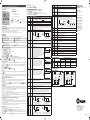
1
strumento di riferimento;
■ l’uscita dalla calibrazione si ha premendo il tasto
OUT1
Uscita canale 1
OUT2
Uscita canale 2
L1
Modifica setpoint canale 1
L2
Modifica setpoint canale 2
Per accedere al menù di configurazione dei parametri, premere per 5 secondi i tasti
+ .
o
selezionare il parametro da modificare.
Con i tasti
per visualizzare il valore.
Premere il tasto
Mantenendo premuto
agire con i tasti
o
per impostare il valore desiderato.
il nuovo valore viene memorizzato e viene visualizzato il parametro successivo.
Al rilascio del tasto
Per uscire dal setup premere il tasto
o attendere 30 secondi.
Allarme
Tasto Info / Enter.
Tasto modifica setpoint 1 / decremento.
Tasto incremento / modifica setpoint 2
Tasto uscita / Stand-by.
Fig.1 - Pannello frontale
INSTALLAZIONE
■ Il L04-- ha dimensioni 110x75x55 mm (LxHxP). Fissare al pannello la placca con 2 viti da 4 o 5 mm di diametro con testa
cilindrica, applicare poi il corpo dello strumento alla placca. Questo fissaggio è indicato per pannelli verticali e per un orientamento
dello strumento con le uscite poste in basso.
■ Eseguire i collegamenti elettrici facendo riferimento al paragrafo “schemi di collegamento”. Per ridurre gli effetti delle perturbazioni
elettromagnetiche, distanziare i cavi delle sonde e di segnale dai conduttori di potenza.
■ Posizionare la sonda T1 in un punto della cella che ben rappresenti la temperatura del prodotto da conservare.
PAR
SCL
RANGE
SPL
SPH
1SP
-50°...SPH
Limite minimo per la regolazione di 1SP.
SPL...150°
Limite massimo per la regolazione di 1SP.
SPL... SPH
1CM
HY; PID
1CH
1HY
1°C;
2°C;
°F
REF; HEA
0...19.9°
1CM=HY
Strumento in autotuning
In tuning: errore di timeout1
In tuning: errore di timeout2
In tuning: errore di over range
MENU INFO
Le informazioni disponibili nel menù info sono:
Temperatura massima registrata sonda 1
Temperatura minima registrata sonda 1
1T0
Modo di regolazione refrigerazione (REF) o riscaldamento (HEA) dell’uscita 1.
Differenziale del termostato. Con 1HY=0 l’uscita rimane sempre spenta.
ON
Tempo minimo di spegnimento
Dopo uno spegnimento, l’uscita 1 rimane disattivata per 1T0 minuti indipendentemente dal valore
della temperatura.
0...19.9°
Banda proporzionale.
Sovraelongazione
Temperatura
Error e a regime
1PB
Temperatura
processo
Sovraelongazione
Tempo dell’azione integrativa.
Temperatura
processo
Tempo dell’azione derivativa.
Il blocco dei tasti impedisce operazioni indesiderate, potenzialmente dannose, che possono avvenire qualora il regolatore operi
in ambiente pubblico. Per inibire tutti i comandi da tastiera impostare LOC=YES nel menù INFO; per ripristinare la normale
funzionalità riprogrammare LOC=NO.
EN
2T1
0...30min
Tempo minimo di attivazione
Dopo una accensione, l’uscita 2 rimane attivata per 2T1 minuti indipendentemente dal valore
della temperatura.
ISTRUZIONI D’USO
IT
2PF
ATM
ON/OFF
AUTOTUNING DEL REGOLATORE IN MODALITA’ PID
1PBx1AR%
1PB
Zona di azione
controllo integrale
Gestione soglie allarme.
NON : tutti gli allarmi di temperatura sono interdetti. (il successivo paramentro visualizzato sarà SB)
ABS : i valori programmati in ALA e AHA rappresentano le reali soglie d’allarme
REL : i valori programmati in ALR e AHR sono i differenziali d’allarme rispetto a 1SP e 1SP+1HY
ON
T[°]
1SP
T[°]
OFF
1SP+1HY+AHR
1SP-1HY -ALR
1SP+AHR
1SP
Allarme di temperatura con soglie relative, con- Allarme di temperatura con soglie relative, controllo in refrigerazione (ATM=REL, 1CH=REF) trollo in riscaldamento (ATM=REL, 1CH=HEA)
-50°...AHA
Soglia d’allarme di bassa temperatura
AHA
ALA...150°
Soglia d’allarme di alta temperatura
ALR
-12.0...0°
Differenziale d’allarme di bassa temperatura.
Con ALR=0 l’allarme di bassa temperatura viene escluso.
AHR
0...12.0°
Differenziale d’allarme di alta temperatura.
Con AHR=0 l’allarme di alta temperatura viene escluso.
ATD
0...120min
Ritardo nella segnalazione dell’allarme di temperatura.
SB
INP
NO/YES
Abilitazione tasto stand-by.
DATI TECNICI
ST1/SN4
Selezione del sensore in ingresso. (vd. tabella caratteristiche ingresso)
Alimentazione
e-mail: [email protected]
http://www.fantinicosmi.it
L04B--/L24E--
Solo nei modelli L04BM2A
RLO
-19.9...RHI
Range minimo della scala
Ad RLO viene assegnato il valore minimo misurato dal trasmettitore (corrispondente a 0V)
RHI
RLO...99.9
Range massimo della scala
Ad RHI viene assegnato il valore massimo misurato dal trasmettitore (corrispondente a 1V)
OS1
1...30min
SIM
0...100
Rallentamento display
vd. tabella caratteristiche ingresso
ADR
1...255
Indirizzo di L04-- per la comunicazione con PC
Precisione di misura
Ritardo della memorizzazione delle temperature minime (TLO) e massime (THI) raggiunte.
Condizioni operative
-10 … +50°C; 15%...80% U.R.
RANGE DI MISURA [PRECISIONE DI MISURA]
INGRESSO
SCL=1°C
SCL=2°C
PTC 1000 Ω
(LS120)
-50/-19.9 ÷ 99.9/150°C
[<±0.3°C(-30÷130°),±1°C]
-50 ÷ 150°C
[<±0.3°C (-30÷130°),±1°C]
-60 ÷ 300°F
[<±0.6°F (-20÷260°),±2°F]
INP=SN4
NTC 10K Ω
(LS130)
-40/-19.9 ÷ 99.9/125°C
[<±0.3°C(-40÷100°), ±1°C]
-40 ÷ 125°C
[<±0.3°C (-40÷100°),±1°C]
-40 ÷ 260°F
[<±0.6°F (-40÷210°),±2°F]
V
TTL
3
4
3
data I/O
4
V IN V-
1PF
ON/OFF
OAU
NON;
THR;
AL0;
AL1
Funzionamento dell’uscita ausiliaria AUX.
NON : uscita disabilitata (sempre spenta). (Il prossimo parametro sarà ATM).
THR : uscita programmata come secondo termostato. (Il prossimo parametro sarà 2SM)
AL0 : apertura dei contatti al presentarsi di una condizione di allarme. (Il prossimo parametro sarà ATM)
AL1 : chiusura dei contatti al presentarsi di una condizione di allarme. (Il prossimo parametro sarà ATM)
ABS;
REL
Modalità setpoint 2.
Il setpoint del canale 2 può essere assoluto (2SM=ABS), o un differenziale relativo al setpoint 1 (2SM=REL)
2SM=ABS
OAU=THR
Stato dell’uscita con sonda difettosa.
Temperatura di commutazione dell’uscita ausiliaria (Il prossimo parametro sarà 2CH)
ON
OFF
OFF
2SP
2SP+2HY
T[°]
Controllo ON/OFF in refrigerazione
(2SM=ABS, 2CH=REF)
2SP-2HY
2SP
T[°]
Controllo ON/OFF in riscaldamento
(2SM=ABS, 2CH=HEA)
2DF -19.9...19.9° Differenziale di temperatura rispetto a 1SP. Il setpoint dell’uscita ausiliaria è pari a 1SP+2DF.
RICALIBRAZIONE
ON
2SM=REL
ON
OFF
OFF
1SP+2DF+2HY
2DF>0
1SP
1SP+2DF
T[°]
EN60730-1; EN60730-2-9;
EN55022 (Classe B); EN50082-1
---
INP=ST1
data I/O
Tempo di ciclo.
E’ il periodo all’interno del quale varia il tempo di ON dell’uscita. Quanto più velocemente il
sistema da controllare risponde alle variazioni della temperatura, tanto minore deve essere il
tempo di ciclo, per ottenere una maggiore stabilità della temperatura, e una minore sensibilità
alle variazioni di carico.
ON
CE (Norme di Riferimento)
SCL=°F
RLO÷RHI [< ± 3mV]
rH
Temperatura
processo
1SP+2DF-2HY
2DF<0
1SP+2DF
1SP
T[°]
Controllo ON/OFF in refrigerazione. Setpoint 2 Controllo ON/OFF in riscaldamento. Setpoint 2
relativo al setpoint 1 (OAU=THR, 2CH=HEA)
relativo al setpoint 1 (OAU=THR, 2CH=REF)
8
230V ~
Range di Misura
vd. tabella caratteristiche ingresso
0÷1V
1PB
1...255s
8(3)A 240V~
8(3)A 240V~
vd. tabella caratteristiche ingresso
RS485
1CT
230Vac±10%, 50/60Hz, 2W
Ingressi
-12.5...12.5° Correzione misura sonda T1
OUT 1
8(3)A
OUT 2
8(3)A
9
10
OUT 1
8(3)A
OUT 2
8(3)A
9
10
5
V+
Tempo
SPL...SPH
OUT1
OUT2
SCHEMI DI COLLEGAMENTO
Reset dell’azione integrativa riferito a 1PB.
Diminuendo il parametro 1AR si restringe la zona di azione del controllo integrativo, e di
conseguenza la sovraelongazione (vedi figura nel parametro 1IT).
2SP
Uscite relè
TLD
1SP
0...100%
Via Dell’Osio 6
20090 Caleppio di Settala MI
TEL. +39 - 02956821
FAX +39 - 0295307006
ALA
L04BM2A
1AR
2SM
L04B-- / L24E--
Stato dell’uscita 2 con sonda difettosa
NON;
ABS;
REL
MODELLO
Sovraelongazione
L’inserimento di un’azione derivativa diminuisce
la sovraelongazione nella risposta. Un’azione
derivativa elevata (1DT alto) rende il sistema molto
sensibile alle piccole variazioni di temperatura, e
può portare instabilità.
Con 1DT=0 il controllo derivativo viene disabilitato.
, premuto per 3 secondi, consente di commutare lo stato del regolatore fra operatività delle uscite e standby (solo con SB=YES).
INSTRUCTIONS FOR USE
L24EM2
Temperatura
0...999s
Tempo minimo di spegnimento.
Dopo uno spegnimento, l’uscita 2 rimane disattivata per 2T0 minuti indipendentemente dal
valore della temperatura.
Tempo
Tempo
1DT
Differenziale del termostato 2. Con 2HY=0 l’uscita ausiliaria rimane sempre spenta.
CARATTERISTICHE INGRESSO
L’inserimento di un’azione integrativa annulla
1SP
l’errore a regime. Il tempo dell’azione integrativa
determina la velocità con cui si raggiunge la
temperatura di regime, ma un’elevata velocità (1IT
basso) può essere causa di sovraelongazione e di
instabilità nella risposta.
Con 1IT=0 il controllo integrativo viene disabilitato.
BLOCCO DELLA TASTIERA
■ munirsi di un termometro di precisione o di un calibratore; verificare che OS1=0 e SIM=0;
■ spegnere e riaccendere lo strumento;
+
e mantenerli premuti fino a che lo strumento visualizza 0AD;
■ durante la fase di autotest premere i tasti
e
selezionare 0AD o SAD: 0AD consente la taratura dello 0, inserendo una correzione costante su tutta la
■ con i tasti
scala di misura. SAD permette la taratura della parte alta della scala di misura con una correzione proporzionale fra il punto di
taratura e lo 0;
■ premere
per visualizzare il valore e agire con
+
o
per far coincidere il valore letto con quello misurato dallo
T[°]
1SP
Controllo ON/OFF in riscaldamento
(1CM=HY, 1CH=HEA)
Il controllo della temperatura avviene variando il
tempo di ON dell’uscita: più la temperatura è vicina 1SP
al setpoint, minore e’ il tempo di attivazione. Una
banda proporzionale piccola aumenta la prontezza
del sistema alle variazioni di temperatura, ma tende
a renderlo meno stabile. Un controllo puramente
proporzionale stabilizza la temperatura all’interno
della banda proporzionale, ma non annulla lo
scostamento dal setpoint.
Con 1PB=0 l’uscita rimane sempre spenta.
STAND-BY
Prima di iniziare
In modalità setup (v. parametri di configurazione): impostare 1CM=PID; accertarsi che 1CH corrisponda al modo di funzionamento
voluto (1CH=REF per refrigerazione, 1CH=HEA per riscaldamento); fissare il setpoint 1SP al valore desiderato.
Avvio della funzione
Durante il funzionamento normale, mantenere premuti i tasti
+
per 3 secondi. Sul display lampeggia 1CT; con
+
o
impostare il tempo di ciclo in modo da caratterizzare la dinamica del processo da controllare. Per abbandonare la funzione di
+
o attendere 30s.
autotuning premere ; per iniziare l’autotuning premere
Durante l’autotuning
Durante tutta la fase di autotuning il display visualizza alternativamente TUN e il valore della temperatura misurata. Se manca
l’alimentazione, alla successiva riaccensione, dopo la fase iniziale di autotest, lo strumento riprende la funzione di autotuning. Per
abbandonare la funzione di autotuning, senza modificare i parametri di controllo, mantenere premuto per 3 secondi il tasto .
Terminato con successo l’autotuning il controllore aggiorna il valore dei parametri di controllo, e inizia a regolare.
Errori
Se la funzione di autotuning non ha esito positivo, sul display lampeggia un codice d’errore:
■ E1 errore di timeout1: il controllore non è riuscito a portare la temperatura all’interno della banda proporzionale. Aumentare 1SP
nel caso di controllo in riscaldamento, viceversa, diminuire 1SP in raffreddamento e riavviare la procedura.
■ E2 errore di timeout2: l’autotuning non è terminato entro il tempo massimo stabilito (1000 tempi di ciclo). Riavviare la procedura
di autotuning e impostare un tempo di ciclo maggiore.
■ E3 over range di temperatura: controllare che l’errore non sia causato da un’anomalia della sonda, quindi diminuire 1SP nel
caso di controllo in riscaldamento, viceversa aumentare 1SP in raffreddamento e riavviare la procedura.
■ Per eliminare l’indicazione d’errore e ritornare in modalità normale premere il tasto .
Miglioramento del controllo
■ per ridurre la sovraelongazione diminuire il reset dell’azione integrativa 1AR;
■ per aumentare la prontezza del sistema diminuire la banda proporzionale 1PB; attenzione: in tale maniera si porta il sistema ad
essere meno stabile (oscillazione della temperatura);
■ per ridurre le oscillazioni della temperatura a regime aumentare il tempo dell’azione integrativa 1IT; si aumenta così la stabilità
del sistema, ma si diminuisce la sua prontezza di risposta;
■ per aumentare la velocità di risposta alle variazioni di temperatura aumentare il tempo dell’azione derivativa 1DT; attenzione:
un valore elevato rende il sistema sensibile alle piccole variazioni e può essere fonte di instabilità.
1SP-1HY
1PB
1CM=PID
■ con l’uscita ausiliaria impostata come termostato (OAU=THR), è possibile modificare il setpoint 2 durante il funzionamento
normale del regolatore.
■ premere e rilasciare il tasto : il led L2 lampeggia, il display visualizza per 1 secondo 2SP, se il setpoint 2 è impostato in modo assoluto (2SM=ABS), oppure visualizza 2DF, se il setpoint 2 è relativo al setpoint 1 (2SM=REL), quindi il valore associato al parametro.
■ agire con i tasti
o
per impostare il valore desiderato.
, o attendere 10s.
■ per memorizzare il nuovo valore premere il tasto
■ per ritornare in modalità normale senza salvare il nuovo valore premere .
OFF
T[°]
1SP+1HY
Tempo minimo di attivazione. (Il parametro successivo sarà 1PF)
Dopo una accensione, l’uscita 1 rimane attivata per 1T1 minuti indipendentemente dal valore
della temperatura.
SETPOINT CANALE 2
0...19.9°
0...30min
1SP-ALR
0...30min
0...999s
2HY
2T0
Modo di regolazione refrigerazione (REF) o riscaldamento (HEA) per l’uscita ausiliaria
Temperatura di commutazione (valore che si desidera mantenere).
1T1
1IT
REF; HEA
OFF
Controllo ON/OFF in refrigerazione
(1CM=HY, 1CH=REF)
0...30min
2CH
ON
Modalità di controllo.
Con 1CM=HY si seleziona la regolazione con isteresi: nel controllo vengono usati i parametri
1HY, 1T0 e 1T1. Con 1CM=PID si seleziona la regolazione Proporzionale-Integrativa-Derivativa:
nel controllo vengono usati i parametri 1PB, 1IT, 1DT, 1AR, 1CT.
1SP
Stato della tastiera (blocco)
Accesso al menù e visualizzazione informazioni.
.
■ Premere e subito rilasciare il tasto
o
selezionare il dato da visualizzare.
■ Con i tasti
per visualizzare il valore.
■ Premere il tasto
■ Per uscire dal menù, premere il tasto
o attendere 10 secondi.
Reset delle memorizzazioni THI, TLO
■ Con i tasti
o
selezionare il dato da resettare.
■ Visualizzare il valore con il tasto .
premere il tasto .
■ Mantenendo premuto il tasto
SETPOINT CANALE 1 (visualizzazione e modifica valore di temperatura desiderato)
■ Premere e rilasciare il tasto : il led L1 lampeggia, il display visualizza per 1 secondo 1SP quindi il valore associato al setpoint.
o
per impostare il valore desiderato (la regolazione è compresa entro il limite minimo SPL e massimo SPH).
■ Agire con i tasti
, o attendere 10s.
■ Per memorizzare il nuovo valore premere il tasto
■ Per ritornare in modalità normale senza salvare il nuovo valore premere .
Il tasto
Scala di lettura (vd. tabella caratteristiche ingresso)
Attenzione: cambiando il valore di SCL vanno assolutamente riconfigurati i parametri riguardanti
le temperature assolute e relative (SPL, SPH, 1SP, 1HY ecc..)
OFF
VISUALIZZAZIONI
Strumento in stand-by
Over range o rottura sonda T1
Allarme alta temperatura
Allarme di bassa temperatura
DESCRIZIONE
ON
FUNZIONAMENTO
In funzionamento normale sul display viene visualizzata la temperatura rilevata oppure una delle indicazioni seguenti:
OAU=THR
INDICAZIONI
■
■
■
■
■
■
Temperatura
DESCRIZIONE
PARAMETRI DI CONFIGURAZIONE
ATM=ABS
Vi ringraziamo per la preferenza accordataci scegliendo un prodotto Fantini Csomi. Prima di procedere all’installazione dello
strumento, leggete attentamente il presente foglio d’istruzioni: solo così potrete ottenere massime prestazioni e sicurezza.
.
ATM=REL
L04B-- / L24E-- ISTRUZIONI D’USO
6
7
8
L04BM2A
230V ~
6
7
L24EM2
Protezione frontale
IP55
reference instrument.
■ Exit from calibration by pressing button
OUT2
Channel 2 output
L1
Channel 1 setpoint modification
L2
Channel 2 setpoint modification
Alarm
Info / Enter button
Modify Setpoint 1 / Decrease button
Increase / Modify Setpoint 2 button
Exit / Stand-by button
Fig.1 - Front panel
INSTALLATION
■ The L04-- sizes 110x75x55 mm (WxHxD). Fix the plate to the panel using 2 cheese-headed screws with 4 or 5 mm diameter
and then apply the instrument casing to the plate. This should be done for vertical panels and for correct positioning of the
instrument with the outlets at the bottom.
■ Make sure that electrical connections comply with the paragraph “wiring diagrams”. To reduce the effects of electromagnetic
disturbance, keep the sensor and signal cables well separate from the power wires.
■ Place the probe T1 inside the room in a point that truly represents the temperature of the stored product.
PAR
SCL
RANGE
SPL
SPH
1SP
-50°...SPH
Minimum limit for 1SP setting
SPL...150°
Maximum limit for 1SP setting.
SPL... SPH
Setpoint (value to be maintained in the room).
1CM
HY; PID
1CH
1HY
1°C;
2°C;
°F
REF; HEA
0...19.9°
1CM=HY
Controller in autotuning
In tuning: timeout1 error
In tuning: timeout2 error
In tuning: overrange error
MENU INFO
The information available in this menu is:
Maximum temperature recorded
Minimum temperature recorded
Refrigerating (REF) or Heating (HEA) control mode.
OFF/ON thermostat differential. With 1HY=0 the output is always off.
ON
1SP-1HY
ON/OFF heating control
(1CM=HY, 1CH=HEA)
1T1
0...30min
Minimum on time. (the following parameter will be 1PF).
After output 1 has been turned on, it remains active for 1T1 minutes regardless of the temperature
value measured.
1PB
0...19.9°
Proportional bandwidth.
remains inactive for 1T0 minutes regardless of the
Overshoot
KEYPAD LOCK
The keypad lock avoids undesired, potentially dangerous operations, which might be attempted when the controllers is operating
in a public place. In the INFO menu, set parameter LOC=YES to inhibit all functions of the buttons. To resume normal operation
of keypad, adjust setting so that LOC=NO.
0...30min
Minimum on time.
After output 2 has been turned on, it remains active for 2T1 minutes regardless of the temperature
value measured.
2PF
ATM
ON/OFF
Auxiliary output state in case of probe failure.
NON;
ABS;
REL
Alarm threshold management.
NON : all temperature alarms are inhibited (the following parameter will be SB).
ABS : the values programmed in ALA and AHA represent the real alarm thresholds.
REL : the values programmed in ALR and AHR are alarm differentials referred to 1SP and 1SP+1HY.
1SP
T[°]
OFF
1SP+1HY+AHR
1SP-1HY -ALR
Temperature alarm with relative thresholds,
refrigerating control (ATM=REL, 1CH=REF)
1SP+AHR
1SP
Temperature alarm with relative thresholds,
heating control (ATM=REL, 1CH=HEA).
ALA
-50°...AHA
Low temperature alarm threshold.
AHA
ALA...150°
High temperature alarm threshold.
ALR
-12.0...0°
Low temperature alarm differential.
With ALR=0 the low temperature alarm is excluded.
AHR
0...12.0°
High temperature alarm differential.
With AHR=0 the high temperature alarm is excluded.
L04B--/L24E--
OUT1
OUT2
230Vac±10%, 50/60Hz, 2W
8(3)A 240V~
8(3)A 240V~
Inputs
see table of input specifications
Measurement range
see table of input specifications
Measurement accuracy
ON
T[°]
see table of input specifications
Operating conditions
-10 … +50°C; 15%...80% r.H.
CE (Reference Norms)
EN60730-1; EN60730-2-9;
EN55022 (Class B); EN50082-1
Front protection
IP55
ATD
0...120min
SB
INP
NO/YES
Stand-by button enabling.
ST1/SN4
Sensor input selection (see table of input specifications).
RLO
-19.9...RHI
Minimum range value
RLO takes the minimum value measured by the transmitter (i.e. the value matching 0V).
RHI
RLO...99.9
Maximum range value
RHI takes the maximum value measured by the transmitter (i.e. the value matching 1V)
Delay before alarm temperature warning.
(LS120/LS130)
OS1
-12.5...12.5° Probe T1 offset.
TLD
1...30min
SIM
0...100
Display slowdown
ADR
1...255
L04-- address for PC communication
1PB
Process
temperature
Delay for minimum temperature (TLO) and maximum temperature (THI) logging.
INPUT SPECIFICATIONS
Time
MODEL
Overshoot
1PBx1AR%
1PB
integral control
action area
Process
temperature
RANGE [MEASUREMENT ACCURACY]
INPUT
L24EM2
1SP
Derivative action time.
SCL=1°C
0÷1V (LS160A)
SCL=2°C
SCL=°F
RLO÷RHI [< ± 3mV]
---
INP=ST1
PTC 1000 Ω
(LS120)
-50/-19.9 ÷ 99.9/150°C
[<±0.3°C(-30÷130°),±1°C]
-50 ÷ 150°C
[<±0.3°C(-30÷130°), ±1°C]
-60 ÷ 300°F
[< ±0.6°F(-20÷260°),±2°F]
INP=SN4
NTC 10K Ω
(LS130)
-40/-19.9 ÷ 99.9/125°C
[<±0.3°C(-40÷100°),±1°C]
-40 ÷ 125°C
[<±0.3°C(-40÷100°),±1°C]
-40 ÷ 260°F
[<±0.6°F(-40÷210°), ±2°F]
L04BM2A
WIRING DIAGRAMS
Overshoot
Response overshoot may be reduced by inserting
a derivative Action. A high derivative action (1DT
high) makes the system very sensitive to small
temperature variations and causes instability. With
1DT=0 the derivative control is disabled.
, when pressed for 3 seconds, allows the controller to be put on a standby or output control to be resumed (with SB=YES only).
1SP
V
TTL
RS485
rH
1PB
3
data I/O
Process
temperature
CONTROLLER AUTOTUNING IN PID MODE
4
3
data I/O
4
V IN VOUT 1
8(3)A
OUT 2
8(3)A
9
10
OUT 1
8(3)A
OUT 2
8(3)A
9
10
5
V+
Time
1AR
0...100%
Reset of integral action time referred to 1PB
Decreasing the parameter 1AR reduces the integral control action zone, and consequently the
overshoot (see figure on paragraph 1IT).
1CT
1...255s
Cycle time.
It’s the period in which the output ON time changes. The quicker the system to be controlled
reacts to temperature variations, the smaller the cycle time must be, in order to obtain higher
temperature stability and less sensitivity to load variations.
1PF
ON/OFF
OAU
NON;
THR;
AL0;
AL1
AUX output operation.
NON : output disabled (always off). (the next parameter will be ATM)
THR : output programmed for second thermostat control (the next parameter will be 2SM).
AL0 : contacts open when an alarm condition occurs (the next parameter will be ATM).
AL1 : contacts make when an alarm condition occurs (the next parameter will be ATM).
ABS;
REL
Setpoint 2 mode.
Channel 2 setpoint may be absolute (2SM=ABS), or a differential relative to setpoint 1 (2SM=REL)
2SM
2SM=ABS
OAU=THR
2SP
SPL...SPH
230V ~
6
7
8
L04BM2A
230V ~
6
7
L24EM2
Auxiliary output switchover temperature (the next parameter will be 2CH)
ON
ON
OFF
OFF
2SP
2SP+2HY
T[°]
2SP-2HY
2SP
ON/OFF control in heating
(2SM=ABS, 2CH=HEA)
T[°]
2DF -19.9...19.9° Temperature differential relative to 1SP. The auxiliary output setpoint is equal to 1SP+2DF
Via Dell’Osio 6
20090 Caleppio di Settala MI
TEL. +39 - 02956821
FAX +39 - 0295307006
ON
ON
2SM=REL
8
Output state in case of probe failure.
ON/OFF control in refrigeration
(2SM=ABS, 2CH=REF)
RECALIBRATION
■ Have a precision reference thermometer or a calibrator to hand. Ensure that OS1=0 and SIM=0.
■ Switch the controller off then on again.
■ During the auto-test phase, press buttons
+
and keep them pressed till the controller shows 0AD.
and
select 0AD or SAD: 0AD allows a calibration of 0, inserting a constant correction over the whole scale
■ With buttons
of measurement. SAD allows a calibration of the top part of the measurement scale with a proportional correction between the
calibration point and 0.
to display the value and then use
+
or
to make the read value coincide with the value measured by the
■ Press
S teady-st ate error
Time
0...999s
Relay outputs
2T1
1SP
Integral action time.
The steady-state error is cancelled by inserting an
integral action. The integral action time, determines
the speed with which the steady-state temperature
is achieved, but a high speed (1IT low) may be the
cause of overshoot and instability in the response.
With 1IT=0 the integral control is disabled.
1DT
Power supply
Minimum off time.
After output 2 has been turned off, it remains inactive for 2T0 minutes regardless of the temperature
value measured.
In the models L04BM2A... only.
Temperature control takes place by changing the
ON time of the output: the closer the temperature
to the setpoint, the less time of activation. A small
proportional band increases the promptness of
response of the system to temperature variations,
but tends to make it less stable. A purely
proportional control stabilises the temperature
within the proportional band but does not cancel
the deviation from setpoint.
With 1PB=0 the output is always off.
STAND-BY
Before starting
In the setup mode (see configuration parameters): set 1CM=PID; make sure that 1CH matches the desired operation mode
(1CH=REF for refrigerating control, 1CH=HEA for heating control); then adjust setpoint 1SP at the desired value.
Start autotuning
During normal operation, keep buttons
+
pressed for 3 seconds. 1CT blinks on the display. With
+
or
set the cycle
time in order to define the dynamic of the process to be controlled. To abort the autotuning function, press ; to start autotuning
+
or wait for 30 seconds.
press
During autotuning
During the entire autotuning phase, the display alternates TUN with the actual temperature measured. In case of power failure,
when power is resumed, after the initial autotest phase, the controller resumes the autotuning function. To abort the autotuning,
without modifying the previous control parameters, keep button
pressed for 3 seconds. After the autotuning has taken place
successfully, the controller updates the control parameters and start to control.
Errors
If the autotuning function failed, the display shows an error code:
■ E1 timeout1 error: the controller could not bring the temperature within the proportional band. Increase 1SP in case of heating
control, vice versa, decrease 1SP in case of refrigerating control and re-start the process.
■ E2 timeout2 error: the autotuning has not ended within the maximum time allowed (1000 cycle times). Re-start the autotuning
process and set a longer cycle time 1CT.
■ E3 temperature overrange: check that the error was not caused by a probe malfunction, then decrease 1SP in case of heating
control, vice versa increase 1SP in case of refrigerating control and then re-start the process.
■ To eliminate the error indication and return to the normal mode, press button .
Control improvement
■ To reduce overshoot, reduce the integral action reset 1AR
■ To increase the response speed of the system, reduce the proportional band 1PB. Caution: doing this makes the system less stable.
■ To reduce swings in steady-state temperature, increase the integral action time 1IT; system stability is thus increased, although
its response speed is decreased.
■ To increase the speed of response to the variations in temperature, increase the derivative action time 1DT. Caution: a high
value makes the system sensitive to small variations and it may be a source of instability.
T[°]
1SP
Minimum off time.
After output 1 has been turned off, it
temperature value measured.
1CM=PID
■ With the auxiliary output set as thermostat control (OAU=THR), it’s possible to modify setpoint 2 during the normal operation
of the controller.
: the LED L2 blinks, the display shows 2SP for 1 second if setpoint 2 is an absolute threshold
■ Press and release button
(2SM=ABS), alternatively the display shows 2DF, if setpoint 2 is a threshold relative to setpoint 1 (2SM=REL), then the value
associated to the parameter appears.
■ Press buttons
or
to set the desired value.
or wait for 10 seconds.
■ To store the new value press button
■ To go back to normal mode without saving the new value, press .
OFF
T[°]
1SP+1HY
0...30min
CHANNEL 2 SETPOINT
Differential of thermostat 2. With 2HY=0 the auxiliary output always remains off.
1SP-ALR
1T0
0...999s
0...19.9°
0...30min
2HY
2T0
OFF
ON/OFF refrigerating control
(1CM=HY, 1CH=REF)
1IT
TECHNICAL DATA
REF; HEA
ON
Control mode.
With 1CM=HY you select control with hysteresis: parameters 1HY, 1T0 and 1T1 are used.
With 1CM=PID you select a Proportional-Integral-Derivative control mode: parameters 1PB, 1IT,
1DT, 1AR, 1CT will be used.
1SP
Keypad state lock
Access to menu and information displayed.
■ Press and immediately release button .
■ With button
or
select the data to be displayed.
■ Press button
to display value.
or wait for 10 seconds.
■ To exit from the menu, press button
Reset of THI, TLO recordings
or
select the data to be reset.
■ With button
■ Display the value with button .
■ While keeping button
pressed, use button
.
CHANNEL 1 SETPOINT (display and modification of desired temperature value)
■ Press and release button
: the LED L1 blinks, the display shows 1SP for 1 second and then the setpoint associated value.
or
to set the desired value (adjustment is within the minimum SPL and maximum SPH limit).
■ Press buttons
■ To store the new value press button
, or wait for 10 seconds.
■ To go back to normal mode without saving the new value, press .
Button
Readout scale (see table of input specifications)
Caution: upon changing the SCL value, it is then absolutely necessary to reconfigure the parameters relevant to the absolute and relative temperatures (SPL, SPH, 1SP, 1HY etc..)
OFF
DISPLAY
Controller in stand-by
Probe T1 overrange or failure
Room high temperature alarm
Room low temperature alarm
DESCRIPTION
ON
OPERATION
During normal operation, the display shows either the temperature measured or one of the following indications:
OAU=THR
Channel 1 output
ATM=ABS
OUT1
To get access to the parameter configuration menu, press button
+
for 5 seconds.
or
select the parameter to be modified.
With button
to display the value.
Press button
By keeping button
pressed, use button
or
to set the desired value.
is released, the newly programmed value is stored and the following parameter is displayed.
When button
To exit from the setup, press button
or wait for 30 seconds.
ATM=REL
INDICATION
■
■
■
■
■
■
Refrigerating control (REF) or heating control mode (HEA) for the auxiliary output.
2CH
Temperature
DESCRIPTION
CONFIGURATION PARAMETERS
Temperature
Thank you for having chosen a Fantini Cosmi product. Before installing the instrument, please read these instructions carefully
to ensure maximum performance and safety.
.
Temperature
L04-- INSTRUCTION FOR USE
OFF
OFF
1SP+2DF+2HY
2DF>0
1SP
1SP+2DF
T[°]
ON/OFF control in refrigeration. Setpoint 2
relative to setpoint 1 (OAU=THR, 2CH=REF)
1SP+2DF-2HY
2DF<0
1SP+2DF
1SP
T[°]
e-mail: [email protected]
http://www.fantinicosmi.it
ON/OFF control in heating. Setpoint 2
relative to setpoint 1 (OAU=THR, 2CH=HEA)
5679450