1
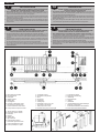
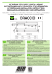
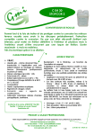
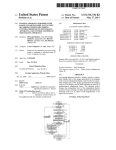
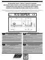
Pag. 1 di 8
ISTRUZIONI PER L'USO E L’INSTALLAZIONE
INSTRUCTIONS POUR L'UTILISATION ET L’INSTALLATION
OPERATING AND INSTALLATION INSTRUCTIONS
GEBRAUCHSANWEISUNGEN UND INSTALLATION
Elettroriduttore irreversibile per cancelli scorrevoli - Motoréducteur irreversible pour portails coulissantes
Irreversible actuator for sliding gates - Selbsthemmender Torantrieb für Schiebetoren
Mod.
K10 SUPER
Misure in mm - Mesures en mm - Measurements in mm - Abmessungen in mm
IMPORTANTI ISTRUZIONI PER LA SICUREZZA
IMPORTANT SAFETY INSTRUCTIONS
I
GB
ATTENZIONE - ƒ IMPORTANTE PER LA SICUREZZA DELLE PERSONE
CHE VENGANO SEGUITE TUTTE LE ISTRUZIONI
CONSERVARE CON CURA QUESTE ISTRUZIONI
1¡ - Tenete i comandi dell'automatismo (pulsantiera, telecomando etc.) fuori dalla portata dei bambini.
I comandi devono essere posti ad unÕaltezza minima di 1,5mt dal suolo e fuori dal raggio dÕazione
delle parti mobili.
2¡ - Effettuare le operazioni di comando da punti ove l'automazione sia visibile.
3¡ - Utilizzare i telecomandi solo in vista dell'automazione.
4¡ - Avvertenze: Sulle altre misure di Protezione contro rischi attinenti l'installazione o l'utilizzazione
del Prodotto vedi, a completamento di questo libretto di Istruzioni, le Avvertenze RIB allegate.
Qualora queste non siano pervenute chiederne l'immediato invio all'Ufficio Commerciale RIB.
LA DITTA RIB NON ACCETTA NESSUNA RESPONSABILITË per eventuali danni provocati dalla
mancata osservanza nell'installazione delle norme di sicurezza e le leggi attualmente in vigore.
WARNING - IT IS IMPORTANT FOR THE SAFETY OF PERSONS
TO FOLLOW ALL INSTRUCTIONS
SAVE THESE INSTRUCTIONS
1¡ - Keep the automatic control (push-button, remote control, etc) out of the reach of children. The
control systems must be installed at a minimum hight of 1.5m from the groundsurface and not
interfere with the mobile parts.
2¡ - Command pulses must be given from sites, where you can see the gate.
3¡ - Use transmitters only if you can see the gate.
4¡ - Warnings: when you have finished reading this instruction booklet, please refer to the RIB
instructions attached for the other precautionary measures against risks connected with the
installation or use of the product. If you have not received these, ask RIB Export Office to send
them immediately.
R.I.B. IS NOT LIABLE for any damage caused by not following the safety regulations and laws at
present in force not being observed during installation.
WICHTIGE ANWEISUNGEN F†R DIE SICHERHEIT
INSTRUCTIONS IMPORTANTES POUR LA SECURITE
F
D
ACHTUNG - UM DIE SICHERHEIT VON PERSONEN VOLLKOMMEN
GARANTIEREN ZU KšNNEN, IST ES WICHTIG, DASS ALLE
INSTALLATIONSVORSCHRIFTEN BEACHTET WERDEN
1¡ - Bewahren Sie die GerŠte fŸr die automatische Bedienung (Drucktaster, Funksender, u.s.w.) an
einem fŸr Kinder unzugŠnglichen Platz auf. Die Steuerungen mŸssen auf einer Mindesthšhe von
1,5 m angebracht werden und sich ausserhalb der Raumes der bewegenden Teile befinden.
2¡ - Die automatische Steuerung darf nur bedient werden, wenn das Tor sichtbar ist.
3¡ - Die Funksender nur benŸtzen, wenn das Tor sichtbar ist.
4¡ - Achtung: FŸr weitere Schutzma§nahmen im Rahmen der Installation und Anwendung der
Produkte siehe die beiliegenden RlB-Sicherheitshinweise, die diese Gebrauchsanleitung
ergŠnzen. Sollten Sie diese nicht erhalten haben, fordern Sie sie bitte sofort bei der RlB
Exportabteilung an.
R.I.B. HAFTET NICHT fŸr eventuelle SchŠden, die bei der Installation durch Nichtbeachtung der
jeweils gŸltigen Sicherheitsvorschriften entstehen.
IL EST IMPORTANT POUR LA SECURITE DES PERSONNES
DE SUIVRE ATTENTIVEMENT TOUTES INSTRUCTIONS
GARDER MODE DÕEMPLOI
1¡ - Gardez les commandes de l'automatisme (boutons poussoirs, tŽlŽcommande etc.) hors de la
portŽe des enfants. Les commandes doivent •tre placŽes au minimum ˆ 1,5 m du sol, et hors de
rayon dÕaction des pi•ces mobiles.
2¡ - Il faut donner les commandes d'un lieu, o• on peut voir la porte.
3¡ - Il faut utiliser les Žmetteurs seulement si on voit la porte.
4¡ - Avertissements: Sur les autres mesures de Protection contre les risques relatifs a l'installation ou
l'utilisation du Produit, voir, ˆ titre de complŽment de ce livret d'instructions, les Avertissements
RIB ci-jointes. Dans le cas o• celles-ci ne vous seraient pas parvenues, en demander l'envoi
immŽdiat au Bureau dÕExportation de RIB.
L'ENTREPRISE R.I.B. N'ACCEPTE AUCUNE RESPONSABILITƒ pour des dommages Žventuels
provoquŽs par le manque d'observation lors de l'installation des normes de sŽcuritŽ et lois
actuellement en vigueur.
®
automatismi per cancelli
automatic entry systems
Pag. 2 di 8
I
IMPORTANTI ISTRUZIONI DI SICUREZZA
PER LÕINSTALLAZIONE
ATTENZIONE - UNA SCORRETTA INSTALLAZIONE PUî PORTARE A DANNI RILEVANTI
SEGUIRE TUTTE LE ISTRUZIONI PER UNA CORRETTA INSTALLAZIONE
1¡ - Questo libretto d'istruzioni • rivolto esclusivamente a del personale specializzato che sia a
conoscenza dei criteri costruttivi e dei dispositivi di protezione contro gli infortuni per i cancelli, le
porte e i portoni motorizzati (attenersi alle norme e alle leggi vigenti).
2¡ - Se non Ž previsto nella centralina elettrica, installare a monte della medesima un'interruttore di tipo
magnetotermico (onnipolare con apertura minima dei contatti pari a 3mm) che riporti un marchio di
conformitˆ alle normative internazionali.
3¡ - Per la sezione ed il tipo dei cavi la RIB consiglia di utilizzare un cavo di tipo NPI07VVF con sezione
minima di 1,5mm2 e comunque di attenersi alla norma IEC 364 e alle norme di installazione vigenti
nel proprio Paese.
F
IMPORTANT MODE DÕEMPLOI DE SECURITE
POUR LÕINSTALLATION
ATTENTION - UNE INSTALLATION INCORRECTE PEUT CAUSER DE GRANDS DOMMAGES
SUIVRE TOUTES INSTRUCTIONS POUR UNE CORRECTE INSTALLATION
1¡ - Ce manuel d'instruction est adressŽ seulement au personnel specialisŽ qui a une
connaissance des crit•res de construction et des dispositifs de protection contre les accidents en ce
qui concerne les portails, les portes et les portes coch•res motorisŽes (suivre les normes et les lois
en vigueur).
2¡ - A fin de procŽder ˆ l'entretien des parties Žlectriques, connecter ˆ l'installation un disjoncteur
differentiel magneto thermique (qui disconnait toutes les branchements de la ligne avec ouverture
min. des branchements de 3 mm ) et qui soit conforme aux normes internationales.
3¡ - Pour la section et le type des c‰bles ˆ installer nous vous conseillons dÕutiliser un cable <HAR>
avec une section min de 1,5 mm 2 en respectant quand m•me la norme IEC 364 et les normes
nationales d'installation.
GB
IMPORTANT SAFETY INSTRUCTION
FOR INSTALLATION
WARNING -INCORRECT INSTALLATION CAN LEAD TO SEVERE INJURY
FOLLOW ALL INSTALLATION INSTRUCTIONS
1¡ - This instruction booklet is exclusively dedicated to specialized staff who are aware of the
construction criteria and of the accident prevention protection devices for motorized gates and
doors (according to the current regulations and laws).
2¡ - To maintain electrical parts safely it is advisable to equip the installation with a differential thermal
magnetic switch (onnipolar with a minimum opening of the contacts of 3mm) and must comply
with the international rules.
3¡ - As for electric cable type and section RIB suggests cable type <HAR> with minimum section of
1,5mm2 and however respect IEC 364 rule and general national security regulations.
D
WICHTIGE SICHERHEITSVORSCHRIFTEN
F†R DIE INSTALLATION
ACHTUNG - EINE FALSCHE INSTALLATION KANN ZU BEDEUTENDEN SH€DEN F†HREN
F†R EINE KORREKTE ANLAGE ALLE ANWEISUNGEN BEFOLGEN
1¡ - Diese Montageanweisung ist ausschlie§lich fŸr geschultes Fachpersonal bestimmt, das
mit den Montagevorschriften und den Schutzvorrichtungen zur Verhinderung von UnfŠllen bei
motorisierten Toren vertraut ist (nach den aktuellen Normen und Gesetzen).
2¡ - FŸr die Wartung der elektrischen Teile ist es ratsam, zwischen der Anlage und dem
Netzanschlu§ einen magnetisch-thermischen Differenzialschalter (mit Mindestšffnung aller
Kontakte von 3 mm) zu montieren, der allen internationalen Normen entspricht.
3¡ - FŸr den Kabelquerschnitt und die Kabeltypen halten Sie sich an den Normen IEC 364 (MindestKabelquerschnitt von 1,5 mm2 mit der Bezeichnung <HAR>) und fŸr die Montage an die Normen
des jeweiligen Landes.
Fig. 1
A - K10 SUPER operator
B - Photoelectric cells (external)
C - Rack
D - Key selector
E - Tuned aerial
F - Flashing lamp
H - Galvanized column for P.E. cells
I - Photo electric cells (internal)
L - Safety strip fixed to column
M - Pneumatic safety strip on edge of gate
A - Elettroriduttore K10 SUPER
B - Fotocellule esterne
C - Cremagliera
D - Selettore a chiave
E - Antenna radio
F - Lampeggiatore
H - Colonnina portafotocellula zincata
I - Fotocellula per protezione interna
L - Costa meccanica fissa sulle colonne
M - Costa pneumatica in punta al cancello
A - Electro-reducteur K10 SUPER
B - Photocellules p/protec. externe
C - Cremaillere
D - Selecteur
E - Antenne radio
F - Signal electrique
H - Poteau zinguŽ p/cellule ne
I - Photocellules p/protection interne
L - Cordon mŽcanique fixŽ sur pilier
M - Cordon pneumatique sur portail
Fig. 2
Fig. 3
A - Torantrieb K10 SUPER
B - Photozelle Toraussenseitig
C - Zahnstange
D - Schlusselschalter
E - Antenne
F - Blinkleuchte
H - Verzinkte MetallsŠule als Photozellentrager
I - Photozelle - Torinnenseitig
L - Sicherheitskontaktleiste auf dem Schiebetor
M - Pneumatische Sicherheitskontaktleiste
Pag. 3 di 8
I
CONTROLLO PRE-INSTALLAZIONE
N.B. é obbligatorio uniformare le caratteristiche del cancello alle norme e
leggi vigenti.
ƒ necessario che la guida abbia alle sue estremitˆ due fermi meccanici (L) (Fig. 2).
Inoltre, le colonne devono avere superiormente delle guide antideragliamento (Fig. 3).
Il cancello deve essere protetto da involontari sganciamenti e deve muoversi senza
attriti.
N.B.: Eliminare fermi meccanici del tipo indicato descritto in figura 3.
Non devono essere presenti, al di sopra del cancello, fermi meccanici perchŽ non
sufficientemente sicuri.
F
PRE-INSTALLATION CHECKS
D
PR†FUNG VON DER MONTAGE
ATTENTION: It is compulsory to conform the gate characteristics to the
current regulations and laws.
The guide needs to have two mechanical stops (L) of the type indicated at its ends (Fig.
2).
In addition, the columns must have anti-deraillement guides at the top (Fig. 3).
The gate must be protected against unintentional derailment and must move without
frictions.
N.B. Eliminate the mechanical stops of the type indicated in Fig. 3.
There must be no mechanical stops above the gate, as they are not safe enough.
CONTROLE PRE-INSTALLATION
N.B.: Il est obligatoire dÕadapter les caracteristiques du portail aux
normes et lois en vigueur.
Il est nŽcessaire que le guidage ait ˆ ses extrŽmitŽs deux arr•ts mŽcaniques (L) du type
indiquŽ (Fig. 2). En plus, les colonnes doivent avoir dans la partie supŽrieure des
guidages antidŽraillement.
Eliminer les arr•ts mŽcaniques du type dŽcrit (Fig. 3).
Le portail doit •tre protŽgŽ contre des dŽcrochages involontaires et doit pouvoir
manoeuvrer sans effort.
Ces arr•ts mŽcaniques ne doivent pas •tre prŽsents au-dessus du portail, car ils ne son
pas suffisamment sžrs.
GB
ACHTUNG: Mann ist verpflichtet die Eigenschaften des Gittertures zu
die Gesetznormen in Einklang zu bringen.
Die FŸhrungsschiene mu§ an beiden Enden mechanische Sperrunger (L) haben, wie in
der Abbildung dargestellt ist (Fig. 2). DarŸberhinaus Mu§en die Saulen Ÿber
Entgleisungsschutzvorrichtungen verfugen (Fig. 3).
Das Gitter soll gegen unvorgesehenes Entkuppeln geschŸtzt sein und ohne reibung
nicht bewegen.
Bitte beachten Sie: Entfernen Sie die beschriebenen mechanischen Sperrungen.
†ber das Gittertor dŸrfen sich keine mechanischen Sperrungen befinden, da diese nicht
sicher genug sind.
CARATTERISTICHE
TECNICHE
CARACTERISTIQUES
TECNIQUES
TECHNICAL
DATA
TECHNISCHE
EIGENSCHAFTEN
Peso max cancello
Poids maxi du portail
Max. leaf weight
Max. Torgewicht
Kg
1000
Velocitˆ di traino
Vitesse de traction
Operating speed
Laufgeschwindigkeit
m/sec
0,173
Forza max di spinta
Force maxi de poussŽe
Thrust force
Max. Schubkraft
N
1060
Cremagliera modulo
Module crŽmaill•re
Rack
Zahnstange Modul
K10 SUPER
4
Alimentazione e frequenza CEE
Alimentation et frequence CEE
EEC Power supply
Stromspannung und frequenz CEE
Potenza motore
Puissance moteur
Motor capacity
Motorleistung
W
290
230V~ 50Hz
Assorbimento
Absorption
Power absorbed
Stromaufnahme
A
1,4
Condensatore
Condensateur
Capacitor
Kondensator
µF
16
n¡
n¡ di cicli
Nbre de cycles
No. cycles
Anzahl der Zyklen
Alimentazione e frequenza CEE
Alimentation et frequence CEE
EEC Power supply
Stromspannung und frequenz CEE
Potenza motore
Puissance moteur
Motor capacity
Motorleistung
W
Assorbimento
Absorption
Power absorbed
Stromaufnahme
A
1,25
n¡ di cicli
Nbre de cycles
No. cycles
Anzahl der Zyklen
n¡
24 - 60s/2s
Lubrificazione a grasso
Graisse
Grease
Schmiere
Peso max
Poids maximun
Weight of electroreducer
Motorgewicht
Kg
Rumorositˆ
Bruit
Noise
GerŠusch
db
<70
Volume
Volume
Volume
Volumen
m3
0,043
Grado di protezione
Ind“ce de protection
Protection
Schutzart
IP
557
8 - 60s/2s
400V 3~ 50Hz
470
Bechem - RHUS 550
25
Pag. 4 di 8
I
FISSAGGIO MOTORE E CREMAGLIERA
F
INSTALLATION DU MOTOR E DE LA CREMAILLERE
La cremagliera va fissata a una certa altezza rispetto alla piastra di
fissaggio del motore.
Questa altezza pu˜ essere variata grazie a delle asole presenti sulla cremagliera.
Le cremagliere non devono essere saldate, ma solo fissate con delle viti filettate al
cancello.
La registrazione in altezza viene fatta affinchŽ il cancello durante il movimento, non si
appoggi sull'ingranaggio di trazione del riduttore (Fig. 4,5).
Per fissare la cremagliera sul cancello si eseguono dei fori di ¯ 7 mm e si filettano
utilizzando un maschio del tipo M8.
L'ingranaggio di traino deve avere circa da 0,5 a 1 mm di agio rispetto alla cremagliera.
La crŽmaill•re doit •tre fixŽe ˆ une certaine hauteur par rapport ˆ la
base du moteur.
Cette hauteur peut •tre modifiŽe gr‰ce ˆ des boutonni•res qui sont prŽsentes sur la
crŽmaill•re.
La crŽmaill•re ne doit pas •tre soudŽe mais seulement fixŽe avec des vis filetŽes ˆ la
grille.
Le rŽglage en hauteur est effectuŽ afin que le portail ne s'appuie pas sur l'engrenage de
traction du rŽducteur (Fig. 4,5). Afin de fixer la crŽmaill•re sur la grille, on perce des trous
de 7 mm de diam•tre et on les fil•tent en employant un tarand du type M8.
L'engrenage de tirage doit avoir un jeu de 0,5 ˆ 1 mm en rapport ˆ la crŽmaill•re.
GB
MOTOR AND RACK INSTALLATION
The rack must be fixed at a certain height with respect to the motor base.
This height can be varied thanks to the slots on the rack.
The rack must not be welded, but simply fixed to the gate with threaded screws.
The height needs to be adjusted so that the gate does not rest on the reduction unit
traction gear (Fig. 4,5).
Holes with a diameter of 7 mm should be made to fix the rack into the gate, and they
should be threaded using a M8 type screw tap.
The pinion must have a clearance of 0,5 to 1 mm with respect to the rack.
D
INSTALLATION DES ANTRIEBS UND DER ZAHNSTANGE
Die Zahnstange mu§ in bestimmten Abstand von der
Verankerungsplatte befestigt werden.
Die Hšhe kann mit Hilfe der auf der Zahnstange befindlichen …sen verstellt werden.
Die Zahnstange darf nicht angeschwei§t, sondern nur mit Hilfe von Gewindeschrauben
an dem Gittertor befestigt werden.
Die Hšheneinstellung soll verhindern, da§ das Gittertor auf dem Antriebszahnrad des
Antriebes aufliegt. (Fig. 4,5).
Um die Zahnstange am der Gittertor fixieren werden Locher mit einem Durchmesser von
7 mm gebohrt, in die ein Gewinde M8 eingeschnitten wird.
Das Zugzahnrad mu§ gegen Ÿber der Zahnstange ein Spiel von 0,5 bis 1 mm haben.
Fig. 5
Fig. 4
F
MANOEUVRE DE SECOURS
GB
EMERGENCY RELEASE
D
NOTENTRIEGELUNG
Effectuer seulement apres avoir coupŽ l'alimentation.
ƒtant irrŽversible, l'electrorŽducteur il n'est pas nŽcessaire de monter une serrure.
Pour ouvrir manuellement le portail en cas de panne de courant, il Faut ouvrir le carter et
tourner la poignŽe dans le sens anti-horaire.
Pour revenir ˆ un fonctionnement Žlectrique tourner-le en sens contraire (Fig. 6).
To be undertaken after disconnecting power supply.
The operator is irreversible and keeps the door closed even without a lockset.
To open the gate manually, in open the motor cover and turn the knob anti-clockwise.
To restore electric working you have to turn the lever clockwise (Fig. 6).
Fig. 6
I
SBLOCCO D'EMERGENZA
Da effettuare dopo aver tolto l'alimentazione elettrica al motore.
L'elettroriduttore • di tipo irreversibile e tiene chiuso senza l'ausilio di serrature.
Per poter aprire manualmente il cancello, qualora venisse a mancare l'energia elettrica,
aprire il carter con l'apposita chiave e ruotare la manopola in senso antiorario.
Per ripristinare il funzionamento elettrico operare in senso contrario (fig. 6).
Die Wartungsarbeit nur nach der Ausschliessung der Spannung auszufŸhren.
Dieser Schiebetorantrieb ist selbsthemmend, so da§ ein zusŠtzliches Elektroschlo§
ŸberflŸssig ist. Um das Schiebetor beim Stromausfall entriegeln zu kšnnen, machen Sie
das AntriebsgehŠuse mit dem beiliegenden SchlŸssel auf und drehen Sie den Griff
gegen den Uhrzeigersinn. Um das Schiebetor wieder in Betrieb zu setzen, drehen Sie
den Griff in die umgekehrte Richtung (Fig. 6).
Pag. 5 di 8
Fig. 7
A) Cancello
Portail coulissant
Sliding gate
Schiebetoren
B) Fotocellule esterne
Cellules pour l'exterieur
External photo-electric cells
Photozelle - Au§enseitig
L) Costa meccanica fissa sulle colonne
Cordon mŽcanique fixŽ sur pilier
Safety strip fixed to column
Sicherheitskontaktleiste auf dem Schiebetor
I) Fotocellula per protezione interna
Photocellules p/protection interne
Photo electric cells (internal)
Photozelle - Torinnenseitig
I
SICUREZZE ELETTRICHE
F
SECURITES ELECTRIQUES
Per un cancello scorrevole con peso superiore a 300 Kg • obbligatorio
installare 2 coppie di fotocellule e coste in numero sufficiente a coprire eventuali punti di
schiacciamento e convogliamento (Fig. 7).
Le fotocellule devono essere poste a un altezza variabile da 40 a 60 cm.
Una coppia di fotocellule devono essere poste all'interno dell'abitazione e coprire l'intera
corsa del cancello.
L'altra coppia deve essere posta all'esterno tra le colonne del cancello.
Per evitare danni fisici alle persone il cancello e la ringhiera devono essere coperti da reti
metalliche impenetrabili (la ringhiera per tutta la corsa del cancello).
Eventuali altri punti di tranciamento o di convogliamento devono essere comunque
protetti o segregati (vedi coste meccaniche o pneumatiche) (Norme UNI 8612).
Il movimento del cancello deve essere sempre segnalato da un lampeggiatore.
Si consiglia l'utilizzo della centralina elettronica di comando AQM11 (per 1 motore
monofase).
Per i collegamenti ed i dati tecnici degli accessori attenersi ai relativi libretti.
Pour un portail coulissant de poids supŽrieur ˆ 300 Kg, il est obligatoire
d'installer 2 couples de photocellules et des montants mobiles en nombre suffisant pour
occuper tous les espaces dangereux (fig. 7).
Les photocellules doivent •tre installŽ ˆ une hauteur variant de 40 ˆ 60 cm.
Un couple de photocellules doit •tre installŽ ˆ l'interieur de l'habitation et couvrir toute la
course du portail.
L'autre couple de photocellules doit •tre installŽ ˆ l'extŽrieur entre les colonnes du
portail.
Pour Žviter de blesser des personnes, le portail et la balustrade doivent •tre recouverts
d'un grillage mŽtallique impŽnŽtrable (la balustrade sur toute la longueur du portail) de
mani•re ˆ interdir le passage d'une main.
Les autre points tranchants ou d'entra”nement Žventuels doivent dans tous les cas •tre
protŽgŽs ou isolŽs (voir profils mŽcaniques ou pneumatiques).
Le mouvement du portail doit toujours Ïetre signalŽ par une lampe clignotant installŽ ˆ
proximitŽ.
Nous vous conseillons dÕutiliser le coffret Žlectronique AQM11 (pour 1 moteur
monophasŽs).
Pour ce qui est des raccordements et des donnŽes techniques des accessoires, se
rŽfŽrer ˆ leur manuel.
GB
ELECTRIC SAFETY DEVICES
D
ELEKTRISCHE SICHERHEITSVORRICHTUNGEN
For a sliding gate weighing more than 300 kg it is obligatory to fit 2 pairs
of photocells and mobile sensors in such a way as to protect any potentially dangerous
openings in the gate (fig. 7).
The photocells must be located at a height of between 40 cm and 60 cm.
One pair of photocells must be located inside the premises and adjusted so that they
cover the entire travel distance of the gate, while the other pair must be located
externally between the gateposts.
In order to avoid the risk of personal injury the gate and the railings must be covered with
fine metal mesh for a distance along the railings such as to cover the full travel distance
of the gate) and in any event there must be no openings of sufficient size to introduce a
hand.
Any other shear points or entanglement/crushing points must be protected or covered
(see mechanical or pneumatic sensors).
Gate movement can be signalled by a flasher unit installed nearby.
Use the AQM11 (for one single-phase motor) electronic control unit.
For connections and technical data of accessories refer to the appropriate booklets.
FŸr ein Schiebetor mit einem Gewicht Ÿber 300 kg sind 2
Fotozellempaare und eine entsprechende Anzahl von verstellbaren Sicherheitssensoren
zur Verriegelung eventueller Zwischenraume zu installieren (Abb. 7).
Die Fotozellen sind auf einer variablen Hohe zwischen 40 und 60 cm zu montieren.
Ein Fotozellenpaar wird innerhalb des eingezŠunten GelŠndes installiert, wo es den
gesamten Fahrweg des Tores abdecken soll.
Das andere Paar ist au§erhalb zwischen den Torpfosten anzubringen.
Um Personenschaden zu vermeiden, mŸssen da Tor und das Gitter mit engmaschigen
Metallnetzen verkleidet sein (das Gitter Ÿber den gesamten Fahrweg des Tores) und
dŸrfen unter keinem UmstŠnden …ffnungen aufweisen, durch die eine Hand gelangen
kann.
Eventuelle weitere Zonen, in deinem Quetsch - oder Schneidgefahr besteht, sind zu
sichern oder zu verkleiden (siehe mechanische oder pneumatische
Sicherheitssensoren).
Es wird die Verwendung der elektronischen SteuergerŠte AQM11 (fŸr 1 einphasige
Motor) empfohlen.
FŸr die AnschlŸsse und technische Daten der Zubehšrteilen verweisen wir auf die
entsprechenden BedienungshandbŸcher.
Pag. 6 di 8
F
REGLAGE FIN DE COURSE
GB
LIMIT SWITCH ADJUSTMENT
D
EINSTELLUNG DES ENDSCHALTERS
F
REGLAGE EMBRAYAGE DE SECURITE
GB
ADJUSTMENT OF THE SAFETY CLUTCH
Pour procŽder au rŽglage:
- DŽbloquer les Žcrous G.
Une fois Žtabli le sens du mouvement de la came H en ouverture et en fermeture,
positionner ˆ vue les deux fins de course F en agissant sur les pommeaux P.Apr•s avoir
contr™lŽ le fonctionnement Žlectrique correct des deux microinterrupteurs, parfaire leur
position jusquÕˆ obtenir lÕarr•t en ouverture et en fermeture dans la position voulue.
- Bloquer les Žcrous G.
NB: le fin de course de sŽrie est destinŽ ˆ des portails de longueur maximum 9 m•tres.
Pour des portails de longueur supŽrieure/ il nous est possible sur demande de vous
fournir des fins de course spŽciaux jusquÕˆ une longueur de 12,5 m•tres.
To adjust the assembly: release nuts G, after establishing the direction of
movement of cam H for opening and closing, position the two limit switches, F, by turning
knobs P and judging by sight.
After checking for correct operation of the two microswitches, precisely adjust their
positions so that the gate will stop in the desired position during opening and closing.
Then fasten nuts G.
N.B. The standard limit switch is used for gates of a max. Iength of 9 meters.
If the gate is longer, "Special" limit switches for gates of up to 12,5 meters can be
supplied.
Fig. 8
I
REGOLAZIONE FINECORSA
Per la regolazione: sbloccare i dadi G.
Stabilito il senso di spostamento della camme H sia in apertura che in chiusura,
posizionare a vista i due finecorsa F agendo sui pomoli P.
Dopo aver verificato il corretto funzionamento elettrico dei due microswitches si
perfeziona la loro posizione fino ad ottenere lÕarresto in apertura e in chiusura nella
posizione voluta, poi si bloccano i dadi G.
N.B. Il finecorsa di normale produzione viene utilizzato per cancelli aventi lunghezza Max
di 9 metri.
In caso il cancello abbia lunghezza superiore, a richiesta si possono fornire i finecorsa
Special, per cancelli fino a 12,5 metri.
Zur Einstellung sind die Muttern G zu lšsen: anschlie§end sind nach
Festlegung der Bewegungsrichtung des Nockens H fŸr …ffnung und Schlie§ung die
beiden Endschalter F durch BetŠtigung der Knšpfe P auf Sicht zu positionieren.
Nach †berprŸfung der beiden Mikroschalter auf deren korrekte Funktionsweise (Elektrik)
ist ihre Position genau einzustellen, bis der Stopp prŠzise in der gewŸnschten …ffnungs bzw. Schlie§stellung erfolgt.
Ziehen Sie nun die Muttern wieder an! †bliche Endschalter werden fŸr Schiebetore mit
einer maximalen LŠnge von 9 Mt. verwendet.
Im falle da§ das Schiebetor eine grš§ere LŠnge aufweist, kšnnen speziale Endschalter
fŸr Schiebetore fŸr bis 12,5 Mt. LŠnge geliefert werden.
Ces operations doivent •tre executŽes aprŽs avoir coupŽ I'alimentation.
1) DŽvisser l'Žcrou (4) ˆ l'aide d'une clef plate de 19 mm.
2) Maintenir l'arbre moteur ˆ l'aide d'une clef plate de 15 mm et serrer la vis (3) pour
donner plus de couple.
DŽsserer pour le diminuer.
3) Apr•s obtention du rŽglage voulu, bien bloquer le contre-Žcrou (4) sur l'arbre moteur.
Faire coulisser le portail Žlectriquement ˆ plusieurs reprises en retenant celui-ci avec les
mains, de mani•re que la force de poussŽe soit lŽg•rement supŽrieure ˆ celle requise
pour mettre le portail en mouvement.
Le rŽglage effectuŽ, se rappeler de bloquer l'Žcrou contre l'arbre moteur.
N.B.: These operations must be executed only after the power supply
has been suspended.
1) Unscrew the unit with a 19 mm wrench (4).
2) Hold the motor with a 15 mm wrench and turn the screw (3) clockwise (with the given
wrench) if you want more force or unscrew it if you need less.
3) After regulating the clutch do not forget to clamp the nut (4) at the shaft's end.
Let the gate move electrically a number of times, holding it with your hands so that the
thrust force is slightly higher than that actually required to move the gate.
When adjustment has been completed, remember to fasten the nut at the motor shaft.
Fig.9
I
REGOLAZIONE FRIZIONE DI SICUREZZA
N.B.: Queste operazioni devono essere eseguite dopo avere tolto
l'alimentazione elettrica del motore.
1 ) Allentare il dado (4) con chiave fissa da 19 mm.
2) Trattenere l'albero motore con chiave fissa da 15 mm e awitare la vite (3) in senso
orario se si vuole dare maggior potenza di spinta, antiorario se serve meno spinta.
3) A regolazione avvenuta ricordarsi di ribloccare il dado (4) contro l'estremitˆ dell'albero.
Far scorrere il cancello elettricamente pi• volte trattenendolo con le mani, in modo che la
forza di spinta sia leggermente superiore a quella richiesta per movimentare il cancello
(NORME UNI 8612).
A regolazione avvenuta ricordarsi di bloccare il dado contro l'albero motore.
D
EINSTELLUNG DER SICHERHEITSKUPPLUNG
N.B.: Diese Operationen sind nur ausfŸhrbar nachdem der Antrieb aus dem Netz
ausgeschaltet worden ist.
1) Die Mutterschraube (4) ist mit dem 19 mm Maulschluessel zu lockern.
2) Die Antriebswelle ist mit einem 15 mm Maulschluessel festzuhalten und gleichzeitig die Schraube
(3) mit dem dazugehšerenden SchlŸessel im Uhrzeigerssinn anzuziehen, wenn Sie dem Antrieb mehr
Schubleistung geben moechten, dagegen, wenn Sie weniger Schubleistung brauchen, ist die
Schraube gegen den Uhrzeigsinn zu lockern.
3) Nach der Einstellung der Rutschkupplung ist die Schraubenmutter (4) wieder gegen Antriebswelle
festzuschrauben. Lassen Sie das Tor nun einige Male hin- und hergleiten Halten Sie es mit den
HŠndem zurŸck, um die Druckkraft leicht Ÿber der fŸr die Torbewegung notwendige zu liegen.
Nach erfolgter Einstellung ist die Schraubenmutter wieder gegen die Motorwelle anzuziehen.
Pag. 7 di 8
MANUTENZIONE
I
Da effettuare solamente da parte di personale specializzato dopo
aver tolto l'alimentazione elettrica al motore.
Ogni anno verificare il serraggio dello sblocco d'emergenza e il funzionamento della
frizione.
In caso di problemi nell'installazione consultare la "TABELLA DEI POSSIBILI
PROBLEMI".
F
ENTRETIEN
Effectuer soulement par personnel specialisŽ apr•s avoir coupŽ
l'alimentation.
VŽrifier chaque annŽe, le serrage du dŽbrayage de sŽcours, ainsi que le bon
fonctionnement de l'embrayage.
En cas de difficultŽs lors de l'installation, consulter le "TABLEAU DES DIFFICULTES
POSSIBLES".
TABELLA DEI POSSIBILI PROBLEMI
I
Problema
GB
MAINTENANCE
To be undertaken only by specialized staff after disconnecting
power supply.
Every year check the emergency release and the clutch adjustment.
If there are any problems during installation, consult the "LIST OF POSSIBLE
PROBLEMS".
D
WARTUNG
GB
LIST OF POSSIBLE PROBLEMS
Die Wartungsarbeit nur durch spezialiesierten Fachleuten nach der
Ausschliessung der Spannung auszufŸhren.
Jedes Jahr nu§man das anziehen der notentriegelung und die arbeitsweise der rutsch
kupplung kontrollieren.
Sofern Installationsprobleme auftreten, ziehen Sie die "TABELLE VON EVENTUELLEN
PROBLEMEN" zu Rate.
Problem
Soluzione
Solution
K10 SUPER non apre, ma chiude
Invertire V con W
K10 SUPER does not open, but closes
K10 SUPER non si ferma sui finecorsa
Invertire il filo 4 col filo 7 sul quadro
elettronico
K10 SUPER does not stop on the limit Invert 4 instead 7 on the electronic panel
switches
K10 SUPER non ha forza di traino
Agire sulla frizione tanto quanto basta a
ripristinare il moto del cancello senza
forzarlo (Fig. 9).
K10 SUPER has not the force to move Operate the clutch as much as i
the gate
necessary to reset the gate movement
without forcing it (Fig. 9).
K10 SUPER non funziona
Controllare l'alimentazione.
K10 SUPER does not work
Control the connections
K10 SUPER dopo pochi secondi si ferma
Regolare il tempo di funzionamento sul
quadro elettronico
K10 SUPER stops after few seconds
Adjust the operating timer on the control
box
F
TABLEAU DES DIFFICULTES POSSIBLES
Probl•me
K10 SUPER nÕouvre pas, mais il ferme
D
Inverser V avec W
K10 SUPER ne sÕ‰rrete pas sur les fins Inverser 4 avec 7 sur le coffret
Žlectronique
de course
K10 SUPER nÕa pas de force de traction
OpŽrer sur lÕembrayage autant quÕil faut
afin de rŽtablir le mouvement du portail
sans le forcer (Fig. 9)
Le K10 SUPER ne fonctionne pas
Controler l'alimentation.
Le K10 SUPER sÕ‰rrete apr•s quelques RŽgler le temps de fonctionnement sur le
secondes.
coffret Žlectronique.
I
N.B.:ƒ obbligatoria la messa a terra dell'impianto
F
N.B:La mise ˆ la terre de l'installation est obligatoire
I dati descritti nel presente manuale sono puramente indicativi.
La RIB si riserva di modificarli in qualsiasi momento.
Realizzare lÕimpianto in ottemperanza alle norme ed alle leggi vigenti.
Les donnees techniques decrites dans ce present manuel sont purement
a titre indicatif.
La RIB se reserve le droit de les modifier ˆ n'importe quel moment.
Adapter les installation du parties electriques aux normes et lois en vigueur.
TABELLE EVENTUELL AUFTRETENDER PROBLEME
Probleme
Solution
Invert on the motor V instead W
Lšsung
K10 SUPER offnet nicht, sondern schlie§t Invertieren Sie V und W.
nur
K10 SUPER halt bei den Endschaltern Invertieren sie 4 und 7 auf die
nicht an
Anschlu§klemme
K10 SUPER hŠlt keine Zugkraft
Betatigen Sie die Kupplung so lange bis
das Tor sich wieder normal bewegt, ohne
es dabei zu belasten (Abb. 9).
Der K10 SUPER funktioniert nicht
†berprŸfen Sie die Stromversorgung.
Der K10 SUPER hŠlt nach wenigen Stellen Sie den Timer richtig ein.
Sekunden an.
GB
N.B.: The system absolutely must be earthed.
The technical data given in this manual are only aproximate.
RIB reserves the right to modify technical data at any time without previous notice.
The installation must be installed according to the current regulations and laws.
D
Bitte beachten Sie: Das Erden der Anlage ist obligatorish
Die in dem vorliegenden Handbuch angegebenen technischen Dater
sind rein informativ.
Firma RIB behalt sich das Rech vor, sie jederzeit zu Šndern.
Die Installation mu§ nach die aktuellen Gesetznormen installiert werden.
K10 SUPER
Codice
Denominazione Particolare
BA01007
BA03000
BA03084
BA03127
BA03132
Scat. sicurezza Super
Finecorsa completo per Super
Gruppo AQM111 400V 50-60Hz
Gruppo AQM11 230V 50-60Hz
Gruppo AQM11 110V 60Hz
BC93110
BC93115
BC93255
Scheda AQM11 230V 50-60Hz
Scheda AQM11 110V 60Hz
Scheda AQM111 400V 50-60Hz
CAL1001
CAL1002
CAL1353
Carter Super
Piastra base Super
Flangia frizione
CCA1002
CCA1007
CCA1054
CCM6205
CCU6010
Piastra da interrare
Gancio per serratura
Protezione ingranaggio Super S.N.
Cuscinetto motore 6205 ZZ
Cuscinetto 6010
CEL1072
CEL1378
Pressacavo nichelato 1/4"
Condensatore 60µF 450V
Codice
Denominazione Particolare
CEL1382
Condensatore 16µF 450V
CME1075
CME1045
CME1080
CME2010
CME4025
CME4051
CME9350
CME9400
Albero di traino
Albero motore K10 Super
Albero motore K10 Super Vent.
Corona con mozzo
Ingranaggio cremagliera
Ing. Finec. Z=22 con foro quadro
Cappellotto K10
Carcassina K10
CMO1180
CMO1181
CMO1183
CMO1190
CMO1196
CMO1197
CMO2039
Statore K10V 230V~ 50Hz 1P
Statore K10V 220V~ 60Hz 1P
Statore K10V 110V~ 60Hz 1P
Statore K10V 400V~ 50Hz 3P
Statore K10V 380V~ 60Hz 3P
Statore K10V 220V~ 60Hz 3P
Rotore K10
CPL1021
CPL1180
CPL1023
CPL1079
Semiscatola superiore
Semiscatola inferiore
Guarnizione PVC
Giunto d'innesto
®
automatismi per cancelli
automatic entry systems
Codice
Denominazione Particolare
CPL1108
CPL1208
Fermo sblocco
Flangia trascinamento
CTC1073
CTC1224
CTC1094
CTC1104
CTC1136
CTC1350
CTC1401
CTC1402
Molla per frizione K8-K10
Spina cilindrica 10x14
Paraolio 17x28x7
Paraolio 50x72x10
Seeger I80
Anello di tenuta OR4437
Paraolio 50x80x8
Paraolio 30x47x7
CVA1025
CVA1370
CVA1383
Cilindretto per serr art. 72210
Boccola bronzo 20x24x15
Tappo cieco K10 3/8
CZM6203
CZM6304
Cuscinetto motore 6203ZZ
Cuscinetto motore 6304ZZ
DST12X35
Grano M12x35
25014 CASTENEDOLO (BS)-ITALY
Via Matteotti, 162
Telefono 030.2135811
Telefax 030.21358279-21358278
http://www.ribind.it - email: [email protected]
La presente macchina non pu˜ funzionare in modo
indipendente ed • destinata ad essere incorporata in
un impianto costituito da ulteriori elementi. Rientra
perci˜ nellÕArt. 4 paragrafo 2 della Direttiva
89/392/CEE (Macchine) e successive modifiche, per
cui segnaliamo il divieto di messa in servizio prima che
lÕimpianto sia stato dichiarato conforme alle
disposizioni della Direttiva
Il Presidente
Cod. AA34925/34900/34945/34915/35030/35009/35007/35010/35005/35001/35006/35002/34920/35000/34950/34910/35020/35008 - 990311 - Rev. 06
Pag. 7 di 8