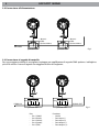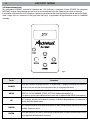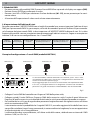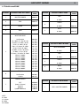
1
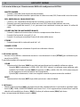
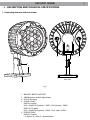
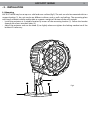
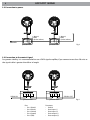
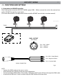
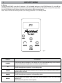
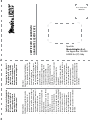
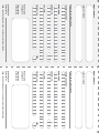
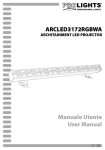
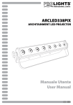
ARCSPOT18RGB
ARCHITECTURAL LIGHTING
Manuale Utente
User Manual
I
GB
REV.001-07/11
ARCSPOT 18RGB
3
INDICE
Sicurezza
Avvertenze generali
Attenzioni e precauzioni per l’installazione
Informazioni generali
4
4
4
1 Descrizione e specifiche tecniche
1. 1 Elementi di comando e collegamenti
1. 2 Descrizione
1. 3 Specifiche tecniche
5
6
6
2 Installazione
2. 1 Montaggio
2. 2 Connessione all’alimentazione
2. 3 Connessione al segnale di controllo
7
8
8
3 Funzioni e impostazioni
3. 1 Funzionamento tramite controller ARCMAT
3. 2 Impostazione base
3. 3 Struttura del menu
3. 4 Configurazioni canali DMX
3. 5 Modalità DMX
3. 6 Impostazione dell’ indirizzo start
3. 7 Tabella canali DMX
3. 8 Istruzioni per la configurazione ARCFULL
3. 9 Funzioni speciali
3. 10 Dimmer
3. 11 Calibrazione bianco
9
10
11
11
12
12
13
14
14
14
15
4 Manutenzione
4. 1 Pulizia sistema ottico e manutenzione
15
Certificato di garanzia
CONTENUTO DELL’IMBALLO:
• ARCSPOT18RGB
• Cavo di sicurezza
• Manuale utente
Music & Lights S.r.l. si riserva ogni diritto di elaborazione in qualsiasi forma delle presenti istruzioni per l’uso.
La riproduzione - anche parziale - per propri scopi commerciali è vietata.
Tutte le specifiche possono essere variate senza alcuna notifica.
ARCSPOT 18RGB
4
ATTENZIONE! Prima di effettuare qualsiasi operazione con l’unità, leggere con attenzione
questo manuale e conservarlo accuratamente per riferimenti futuri. Contiene informazioni
importanti riguardo l’installazione, l’uso e la manutenzione dell’unità.
SICUREZZA
Avvertenze generali
• I prodotti a cui questo manuale si riferisce sono conformi alle Direttive della Comunità Europea e pertanto recano la sigla .
• Il dispositivo funziona con pericolosa tensione di rete 230V~. Non intervenire mai al suo interno al di fuori delle operazioni descritte nel presente manuale; esiste il pericolo di una scarica elettrica.
• È obbligatorio effettuare il collegamento ad un impianto di alimentazione dotato di un’efficiente messa a terra (apparecchio di Classe I secondo norma EN 60598-1). Si raccomanda, inoltre, di proteggere le linee di alimentazione delle unità
dai contatti indiretti e/o cortocircuiti verso massa tramite l’uso di interruttori differenziali opportunamente dimensionati.
• Le operazioni di collegamento alla rete di distribuzione dell’energia elettrica devono essere effettuate da un installatore elettrico qualificato. Verificare che frequenza e tensione della rete corrispondono alla frequenza ed alla tensione
per cui l’unità è predisposta, indicate sulla targhetta dei dati elettrici.
• L’unità non per uso domestico solo per uso professionale.
• Evitare di utilizzare l’unità:
- in luoghi soggetti a vibrazioni, o a possibili urti;
- in luoghi a temperatura superiore ai 40°C o inferiori a -20°C.
• Evitare che nell’unità penetrino liquidi infiammabili, acqua o oggetti metallici.
• Non smontare e non apportare modifiche all’unità.
• Tutti gli interventi devono essere sempre e solo effettuati da personale tecnico qualificato. Rivolgersi al più vicino
centro di assistenza tecnica autorizzato.
• Se si desidera eliminare il dispositivo definitivamente, consegnarlo
per lo smaltimento ad un’istituzione locale per il riciclaggio.
Attenzioni e precauzioni per l’installazione
• Non guardare direttamente il fascio luminoso.
• Ogni persona coinvolta con l’installazione e la manutenzione di questo prodotto deve essere qualificata e seguire le
istruzioni di questo manuale
• Prima di iniziare qualsiasi operazione di manutenzione o pulizia sull’unità togliere la tensione dalla rete di alimentazione.
• Installare l’unità in un luogo ben ventilato.
• Mantenere materiali infiammabili ad una distanza di sicurezza dall’unità.
• I filtri, le lenti o gli schermi ultravioletti se danneggiati possono limitare la loro efficienza.
• I LED devono essere sostituiti se danneggiati o termicamente deformati.
• Per la pulizia del prodotto non usare solventi tipo acetone o alcool per non danneggiare la finitura esterna.
INFORMAZIONI GENERALI
Spedizioni e reclami
Le merci sono vendute “franco nostra sede” e viaggiano sempre a rischio e pericolo del distributore/cliente. Eventuali
avarie e danni dovranno essere contestati al vettore. Ogni reclamo per imballi manomessi dovrà essere inoltrato entro 8
giorni dal ricevimento della merce.
Garanzie e resi
Il prodotto è coperto da garanzia in base alle vigenti normative. Sul sito www.musiclights.it è possibile consultare il testo
integrale delle “Condizioni Generali di Garanzia”. Si prega, dopo l’acquisto, di procedere alla registrazione del prodotto
sul sito www.musiclights.it. In alternativa il prodotto può essere registrato compilando e inviando il modulo riportato
alla fine del manuale. A tutti gli effetti la validità della garanzia è avallata unicamente dalla presentazione del certificato
di garanzia. Music & Lights constata tramite verifica sui resi la difettosità dichiarata, correlata all’appropriato utilizzo, e
l’effettiva validità della garanzia; provvede quindi alla riparazione dei prodotti, declinando tuttavia ogni obbligo di risarcimento per danni diretti o indiretti eventualmente derivanti dalla difettosità.
Le informazioni riportate in questo manuale sono state attentamente controllate.
Music & Lights S.r.l. non si assume, tuttavia, responsabilità derivanti da eventuali inesattezze.
ARCSPOT 18RGB
5
- 1 - DESCRIZIONE E SPECIFICHE TECNICHE
1.1 Elementi di comando e di collegamenti
4
5
2
3
Vista Posteriore
1
1.
2.
3.
4.
Fig.1
Staffa BASE DI SUPPORTO
bRACCIO direzionabile per regolazione inclinazione
fORI per il fissaggio
CAVO DI SEGNALE
DMX IN (3 pole):
Pin1= shield, Pin2 (black) = DMX -, Pin3 (white) = DMX +
DMX OUT (3 pole):
Pin1= shield, Pin4 (green) = DMX -, Pin5 (red) = DMX +
5. CAVO DI ALIMENTAZIONE
L = Brown, N = Blue, E = Green/Yellow
ARCSPOT 18RGB
6
1.2 Descrizione
ARCSPOT18RGB è un illuminatore compatto basato su tecnologia LED, dotato di 18 LEDs a miscelazione
RGB. Il corpo di questo proiettore è stato disegnato per essere integrato in qualsiasi contesto architettonico, anche all’esterno, grazie al suo grado di isolamento interno IP67. Nonostante le dimensioni compatte, l’unità di alimentazione è integrata all’interno del proiettore, garantendo un montaggio estremamente
semplificato e rapido. ARCSPOT18RGB è la scelta ideale per progetti d’impatto dove siano richieste elevate
performance e durabilità.
1.3 Caratteristiche tecniche
Sorgente luminosa e ottica
• 18 x 1W CREE LED RGB (6 rosso, 6 verde, 6 blu).
• Angolo di proiezione: 15°.
• Lumen: 610 lm.
• Lux@2m: 1560 lux.
• Sistema di sintesi colore: miscelazione RGB (>16 milioni di colori).
• Durata media diodi LED: >50.000 ore.
Funzionamento ed elettronica
• Modalita di funzionamento: DMX512, colori statici.
• Funzioni: RGB (0-100%), dimmer, regolazione curva dimmer, calibrazione colori.
• Interfaccia di controllo: DMX coder esterno ARCMAT opzionale.
• Silenziosità di funzionamento, proiettore privo di ventole e struttura disegnata per avere una dissipazione a convezione naturale.
Corpo e alimentazione
• Struttura esterna: alluminio, vetro temperato.
• Grado di isolamento: IP67.
• Bilanciamento temperatura e pressione attraverso valvole di sfiato GORE microforate.
• Regolazione di inclinazione proiettore tramite snodo orientabile.
• Condizioni di esercizio: -40°C/+50°C.
• Alimentazione: interna 100-240V 50/60Hz.
• Alimentazione/Segnale: cavi a 3/5 conduttori.
• Assorbimento massimo: 26W.
• Peso: 2,7kg.
• Dimensioni: 150x145x245mm.
150
145
Photometric data
245
Illuminance at a Distance
15°
190
3.3m
6.7m
10.0m
13.3m
16.7m
20.0m
Center Beam LUX
Field Width
447.46 LUX
1.6m
1.5m
111.87 LUX
3.2m
3.0m
49.72 LUX
4.8m
4.5m
27.97 LUX
6.3m
6.1m
17.90 LUX
7.9m
7.6m
9.5m
9.1m
12.43 LUX
Vert. Spread: 26.8°
Horiz. Spread: 25.6°
ARCSPOT 18RGB
7
- 2 - INSTALLAZIONE
2.1 Montaggio
L’ ARCSPOT18RGB può essere collocato su un piano solido (fig.2). Inoltre, grazie alle possibilità di fissaggio
con la staffa di supporto (1), l’unità può essere montata su diverse superfici come pareti e soffitti. Per il
fissaggio occorrono dei supporti robusti per il montaggio. L’area di collocazione deve avere una stabilità
sufficiente e supportare almeno 10 volte il peso dell’unità.
Inoltre, assicurarsi di rispettare tutte le avvertenze, in materia di sicurezza, per tali proiettori.
• Fissare il proiettore attraverso la staffa di supporto (1) ad una collocazione idonea, mediante l’inserimento delle viti nei 4 fori (3).
• Orientare il proiettore intervenendo, se necessario, sul braccio di regolazione (2).
2
Fig.2
1
3
ARCSPOT 18RGB
8
2.2 Connessione all’alimentazione
L N E
L (Brown)
N (Blu)
E (Green/Yellow)
L N E
L (Brown)
N (Blu)
E (Green/Yellow)
POWER
junction box
junction box
Fig.3
2.3 Connessione al segnale di controllo
Per una maggiore stabilità, è consigliato, impiegare un amplificatore di segnale DMX qualora si colleghino
più di 20 unità o il cavo di segnale sia maggiore di 60 m di lunghezza.
Pin3 2 1 4 5
Pin3 2 1 4 5
SIGNAL IN
SIGNAL OUT
junction box
Pins:
• Pin 1 Shield
• Pin 2 (black)
• Pin 3 (white)
• Pin 4 (green)
• Pin 5 (red)
junction box
Functions:
• Gnd/0
• Data input (-)
• Data input (+)
• Data output (-)
• Data output (+)
Fig.4
ARCSPOT 18RGB
9
- 3 - FUNZIONI E IMPOSTAZIONI
3.1 Funzionamento tramite controller ARCMAT
Dopo aver effettuato il collegamento dell’ARCSPOT18RGB all’alimentazione (230V~ 50Hz), collegare l’unità
al controller esterno ARCMAT attraverso il cavo di segnale.
(Per ulteriori informazioni sul funzionamento del controller ARCMAT consultare il relativo manuale dedicato).
............
Power
ARCMAT
DMX - OUTPUT
Presa XLR
2
1
3
Pin1 : Massa - Schermo
Pin2 : - Negativo
Pin3 : + Positivo
Pin1 : Massa - Schermo (Nero)
Pin2 : - Negativo (Verde)
Pin3 : + Positivo (Rosso)
CONNETTORE DI SEGNALE
Fig.5
NOTA
• Connettere il controller ARCMAT alle unità disposte in serie che si desidera controllare.
• Tutte le unità connesse all’ARCMAT devono essere settate allo stesso modo per poter funzionare correttamente.
• Impostare i parametri e le funzioni sulle unità attraverso il controller.
• Si possono controllare contemporaneamente fino a 20 unità collegate in serie.
ARCSPOT 18RGB
10
3.2 Impostazione base
Per accendere l’ARCMAT, inserire le 2 batterie da 1.5V (incluse), e premere il tasto POWER. Per spegnere
l’ARCMAT, invece, non premere nessun tasto o non assegnare nessuna funzione per circa un minuto.
Il controller dispone di un LED display e 4 pulsanti per accesso alle funzioni del pannello di controllo (fig.6).
Nota: Dopo circa un minuto fra due pressioni dei tasti, la procedura d’impostazione entra in modalità
standby.
DMX
Fig.6
Tasto
Istruzioni
POWER
Tasto per l’accensione dell’ARCMAT. Il dispositivo si spegnerà automaticamente se
passerà circa un minuto senza premere tasti, o assegnare funzioni.
MENU
Premendo questo tasto, è possibile selezionare la funzione desiderata: DMX,
PERSON, CALIB, DIMMER, STATIC, SETTING (Vedere paragrafo 3.3).
Con questo tasto è possibile anche tornare ad un opzione del MENU precedente.
UP
Per scorrere attraverso le diverse funzioni in ordine discendente o aumentare il
valore della funzione stessa.
DOWN
Per scorrere attraverso le diverse funzioni in ordine ascendente o diminuire il valore della funzione stessa.
ENTER
Tasto per entrare nel menu selezionato o confermare il valore attuale della funzione o l’opzione all’interno di un menu.
ARCSPOT 18RGB
11
3.3 Struttura del menu
ATTENZIONE! Per l ‘ARCSPOT18RGB sono abilitate sul controller ARCMAT solo le funzioni riportate di seguito:
DMX
[001-512]
ARC 1
ARC 1 + D
PERSON
ARC FULL
REMOTE
SOLID
WHITE01
WHITE02
CALIB
..
.
WHITE 11
RED[000-255]
GREN[000-255]
BLUE[000-255]
RED[000-255]
RGB TO W
MENU
GREN[000-255]
BLUE[000-255]
(1)
OFF
DIM 1
DIMMER
DIM 2
DIM 3
DIM 4
RED[000-255]
STATIC
GREN[000-255]
BLUE[000-255]
STRB[000-20]
OFF
COLOR
RGB TO W
UC
SETTINGS
RESET
NO
YES
3.4 Configurazioni canali DMX
L’ ARCSPOT18RGB dispone di 4 configurazioni dei canali DMX a cui si può accedere dal pannello di controllo.
• Premere il tasto MENU fino a quando sul display non appare [PERSON], quindi premere il tasto ENTER.
• Attraverso i tasti UP e DOWN selezionare la configurazione dei canali DMX che si desidera (ARC 1 - ARC1+D
- ARC FULL - SOLID).
Nota: l’impostazione REMOTE è una funzione non abilitata.
Le tabelle a pagina 13 indicano le modalità di funzionamento e i relativi valori DMX. Come interfaccia DMX,
l’unità possiede cavo di segnale a 3 fili.
ARCSPOT 18RGB
12
3.5 Modalità DMX
• Per poter entrare nella modalità DMX; Premere il tasto MENU fino a quando sul display non appare [DMX].
• Premere il tasto ENTER per confermare la scelta.
• Premere i tasti UP o DOWN per selezionare il valore desiderato [001 - 512]; tenere premuto per lo scorrimento veloce.
• Al termine dell’impostazione il valore verrà salvato automaticamente.
3.6 Impostazione dell’indirizzo di start
Per poter comandare l’ ARCSPOT18RGB con un’unità di comando luce, occorre impostare l’indirizzo di start
DMX per il primo canale DMX. Se, per esempio, sull’unità di comando è previsto l’indirizzo 33 per comandare la funzione del primo canale DMX, si deve impostare sull’ ARCSPOT18RGB l’indirizzo di start 33. Le altre
funzioni del pannello saranno assegnate automaticamente agli indirizzi successivi. Segue un esempio con
indirizzo 33 di start e una configurazione a 4 e a 7 canali DMX:
Numero
canali DMX
Indirizzo di
start (esempio)
Indirizzo DMX
occupati
Prossimo indirizzo di start
possibile per unità n°1
Prossimo indirizzo di start
possibile per unità n°2
Prossimo indirizzo di start
possibile per unità n°3
4
33
33-36
37
41
45
7
33
33-39
40
47
54
Esempio di configurazione a 7 canali DMX (modalità ARCFULL)
DMX Address: 33
DMX Address: 40
DMX Address: 47
DMX Address: 54
. . . . . . . . . . . .
DMX512 Controller
La connesione DMX è realizzata utilizzando cavi schermati, 2 poli + massa ritorti,
con impendenza 120Ω e bassa capacità. Per il collegamento fare riferimento allo
schema di connessione riportato a pag. 8.
Per passaggi lunghi può essere necessario l'inserimento di un amplificatore DMX.
In tal caso, è sconsigliato utilizzare nei collegamenti cavo bilanciato microfonico
poiché non è in grado di trasmettere in modo affidabile i dati di controllo DMX.
Fig.7
• Collegare l’uscita DMX del controller con l’ingresso DMX della prima unità;
• Collegare, quindi, l’uscita DMX con l’ingresso DMX della successiva unità; l’uscita di quest’ultima con
l’ingresso di quella successiva e via dicendo finché tutte le unità sono collegate formando una catena.
• Per installazioni in cui il cavo di segnale deve percorrere lunghe distanze è consigliato inserire sull’ultima
unità una terminazione DMX.
La terminazione evita la probabilità che il segnale DMX 512, una volta raggiunta la fine della linea stessa
venga riflesso indietro lungo il cavo, provocando, in certe condizioni e lunghezze, la sua sovrapposizione
al segnale originale e la sua cancellazione.
La terminazione deve essere effettuata, sull’ultima unità della catena, saldando una resistenza di 120Ω
(minimo 1/4W) tra i Pin 2 e 3.
ARCSPOT 18RGB
13
3.7 Tabella canali DMX
Channel
Function in ARC FULL mode
DMX
value
1
MASTER DIMMER
000-255
2
RED
000-255
Channel
1
2
3
GREEN
000-255
4
BLUE
000-255
3
Function in ARC1 mode
DMX
value
RED
0-100%
000-255
GREEN
0-100%
000-255
BLUE
0-100%
000-255
Function in ARC1+D mode
DMX
value
COLOR MACRO +
WHITE BALANCE
5
No function
R*: 100% / G*: Up / B*: 0%
R: Down / G: 100% / B: 0%
R: 0% / G: 100% / B: Up
R: 0% / G: Down / B: 100%
R: Up / G: 0% / B: 100%
R: 100% / G: 0% / B: Down
R: 100% / G: Up / B: Up
R: Down / G: Down / B: 100%
White 1: 3200 K
White 2: 3400 K
White 3: 4200 K
White 4: 4900 K
White 5: 5600 K
White 6: 5900 K
White 7: 6500 K
White 8: 7200 K
White 9: 8000 K
000-010
011-035
036-060
061-085
086-110
111-135
136-160
161-185
186-210
211-215
216-220
221-225
226-230
231-235
236-240
241-245
246-250
251-255
Channel
1
2
3
4
MASTER DIMMER
0-100%
000-255
RED
0-100%
000-255
GREEN
0-100%
000-255
BLUE
0-100%
000-255
Channel
Function in SOLID mode
DMX
value
1
RGB + MASTER DIMMER
000-255
STROBE
6
No function
1-20 Hz
000-005
006-255
DIMMER SPEED
7
NOTE
R*=Red
G*=Green
B*=Blue
W*=White
OFF
Speed 1 (fastest)
Speed 2
Speed 3
Speed 4 (slowest)
000-009
010-069
070-129
130-189
190-255
14
ARCSPOT 18RGB
3.8 Istruzioni di base per il funzionamento DMX nella configurazione ARCFULL
MASTER DIMMER
• Il canale 1 controlla l’intensità di luce del proiettore.
• Quando il cursore del controller è posizionato al valore massimo (255) l’intensità d’uscita è massima.
RED, GREEN E BLUE, COLOR SELECTION
• I canali 2, 3 e 4, controllano d’intensità dei Led relativi al colore rosso, verde, blu.
• Quando il cursore è posizionato al valore massimo (255) l’intensità del colore è massima.
• I valori DMX regolati dai canali 2, 3 e 4, possono essere combinati insieme per creare 16 milioni di
colori.
COLORE MACRO E BILANCIAMENTO BIANCO
• Il canale 5 seleziona la macro colore e bianchi a temperatura colore diversa.
• Il canale 5 ha la priorità sui canali 2, 3 e 4.
• Il canale 1 è usato per controllare l’intensità di colore delle macro.
STROBE
• Il canale 6 controlla la strobo dei canali da 1 a 5.
DIMMER SPEED
• Il canale 7 è usato per selezionare il tipo di curva dimmer richiesto.
3.9 Funzioni speciali
• Premere il tasto MENU e selezionare attraverso i tasti direzionali la voce [SETTINGS]; per confermare premere il tasto ENTER.
È possibile accedere alle seguenti funzioni:
COLOR
• Selezionando la funzione [COLOR] è possibile attivare/disattivare le modalità calibratura colore.
-- Quando [RGB] è selezionato, su RGB =255, 255, 255 il colore è visualizzato come calibrato nella
modalità CAL2 (RGB). Quando [COLOR] è impostato su [OFF], su RGB =255, 255, 255 il colore non può
essere regolato e l’uscita mostrerà la massima potenza.
-- Quando [UC] è selezionato, i colori sono regolati secondo un preset universale standard.
RESET
• Selezionando la funzione [RESET] è possibile ripristinare i valori di default.
3.10 Dimmer
• Selezionando la funzione [DIM] è possibile entrare nella modalità dimmer. In particolare, quando è impostato su [OFF], L’RGB e il MASTER DIMMER sono lineari. Dim 1/2/3/4 rappresentano invece diversi valori di
velocità nella modalità non lineare; [DIM 1] è il valore più veloce mentre [DIM 4] il più lento.
Nota. Le impostazioni di fabbrica sono su [DIM 4].
ARCSPOT 18RGB
15
3.11 Calibrazione bianco
Per impostare il bilanciamento personalizzato della temperatura colore bianco:
• Premere il tasto MENU fino a quando sul display non appare [CALIB], quindi premere il tasto ENTER.
• Selezionare una delle 11 impostazioni colore bianco pre-programmate (WHITE01 - WHITE11).
• Le impostazioni possono essere modificate, intervenendo sui valori (000 - 255) relativi ai canali rosso, verde, blu (Red - Green - Blue), attraverso i tasti UP e DOWN.
Nota. Nella configurazione ARCFULL è possibile effettuare il bilanciamento personalizzato della temperatura colore bianco selezionando le impostazioni WHITE01 - WHITE09 del canale 5.
• Selezionare [RGB] per impostare i valori (000 - 255) relativi ai canali rosso, verde e blu.
- 4 - MANUTENZIONE
4.1 Pulizia sistema ottico e manutenzione
• Durante gli interventi, assicurarsi che l’area sotto il luogo di installazione sia libera da personale non
qualificato.
• Spegnere l’unità, scollegare il cavo di alimentazione ed aspettare finché l’unità non si sia raffreddata.
• Tutte le viti utilizzate per l’installazione dell’unità e le sue parti devono essere assicurate saldamente e
non devono essere corrose.
• Alloggiamenti, elementi di fissaggio e di installazione devono essere totalmente esenti da qualsiasi deformazione.
• I cavi di alimentazione devono essere in condizione impeccabile e devono essere sostituiti immediatamente nel momento in cui anche un piccolo problema viene rilevato.
• Si dovrebbe procedere, ad intervalli regolari, alla pulizia della parte frontale per asportare polvere, fumo
e altre particelle. Solo così, la luce può essere irradiata con la luminosità massima. Per la pulizia usare un
panno morbido, pulito e un detergente per vetri come si trovano in commercio. Quindi asciugare le parti
delicatamente.
ARCSPOT 18RGB
1
TABLE OF CONTENTS
Safety
General instructions
Warnings and installation precautions
General information
2
2
2
1 Description and technical specifications
1. 1 Operating elements and connections
1. 2 Description
1. 3 Technical specifications
3
4
4
2 Installation
2. 1 Mounting
2. 2 Connection to power
2. 3 Connection to the control signal
5
6
6
3 Functions and settings
3. 1 Operation through ARCMAT controller
3. 2 Basic
3. 3 Menu structure
3. 4 DMX configurations
3. 5 DMX Mode
3. 6 Setting the start
3. 7 DMX control
3. 8 Basic instructions for DMX operation ARCFULL
3. 9 Special functions
3. 10 Dimmer
3. 11 White calibration
7
8
9
9
10
10
11
12
12
12
13
4 Maintenance
4. 1 Cleaning the unit and maintenance
13
Warranty
PACKING CONTENT:
• ARCSPOT18RGB
• Safety cable
• User manual
All rights reserved by Music & Lights S.r.l. No part of this instruction manual may be.
Reproduced in any form or by any means for any commercial use.
Design and specifications are subject to change without notice.
ARCSPOT 18RGB
2
WARNING! Before carrying out any operations with the unit, carefully read this instruction
manual and keep it with cure for future reference. It contains important information about the
installation, usage and maintenance of the unit.
SAFETY
General instructions
• The products referred to in this manual conform to the European Community Directives and are therefore marked with .
• The unit is supplied with hazardous network voltage (230V~). Leave servicing to skilled personnel only. Never make
any modifications on the unit not described in this instruction manual, otherwise you will risk an electric shock.
• Connection must be made to a power supply system fitted with efficient earthing (Class I appliance according to
standard EN 60598-1). It is, moreover, recommended to protect the supply lines of the units from indirect contact and/
or shorting to earth by using appropriately sized residual current devices.
• The connection to the main network of electric distribution must be carried out by a qualified electrical installer. Check that
the main frequency and voltage correspond to those for which the unit is designed as given on the electrical data label.
• This unit is not for home use, only professional applications.
• Never use the fixture under the following conditions:
- in places subject to vibrations or bumps;
- in places with a temperature of over 40°C or less than 20°C.
• Make certain that no inflammable liquids, water or metal objects enter the fixture.
• Do not dismantle or modify the fixture.
• All work must always be carried out by qualified technical personnel. Contact the nearest sales point for an inspection
or contact the manufacturer directly.
• If the unit is to be put out of operation definitively, take it to a local recycling
plant for a disposal which is not harmful to the environment.
Warnings and installation precautions
• Never look directly at the light beam.
• Every person involved with installation and maintenance of this device have to be qualified and follow the instructions of this manual.
• Before starting any maintenance work or cleaning the projector, cut off power from the main supply.
• Install the fixture in a well ventilated place.
• Keep any inflammable material at a safe distance from the fixture.
• Shields, lenses or ultraviolet screens shall be changed if they have become damaged to such an extent that their effectiveness is impaired.
• The lamp (LED) shall be changed if it has become damaged or thermally deformed.
• When cleaning loudspeakers, please do not use solvents such as acetone or alcohol, since they may damage the of
the unit outer finish.
GENERAL INFORMATION
Shipments and claims
The goods are sold “ex works” and always travel at the risk and danger of the distributor. Eventual damage will have to be
claimed to the freight forwarder. Any claim for broken packs will have to be forwarded within 8 days from the reception
of the goods.
Warranty and returns
The guarantee covers the fixture in compliance with existing regulations. You can find the full version of the “General
Guarantee Conditions” on our web site www.musiclights.it. Please remember to register the piece of equipment soon
after you purchase it, logging on www.musiclights.it. The product can be also registered filling in and sending the form
available on your guarantee certificate. For all purposes, the validity of the guarantee is endorsed solely on presentation
of the guarantee certificate. Music & Lights will verify the validity of the claim through examination of the defect in relation to proper use and the actual validity of the guarantee. Music & Lights will eventually provide replacement or repair of
the products declining, however, any obligation of compensation for direct or indirect damage resulting from faultiness.
The information provided in this manual has been carefully checked.
However Music & Lights S.r.l. is not responsible for any possible inaccuracy.
ARCSPOT 18RGB
3
- 1 - DESCRIPTION AND TECHNICAL SPECIFICATIONS
1.1 Operating elements and connections
4
5
2
3
Rear view
1
Fig.1
1.
2.
3.
4.
Bracket-BASED SUPPORT
ARM direction and tilt adjustment
Holes for fixing
SIGNAL CABLE
DMX IN (3 pole):
Pin1= shield, Pin2 (black) = DMX -, Pin3 (white) = DMX +
DMX OUT (3 pole):
Pin1= shield, Pin4 (green) = DMX -, Pin5 (red) = DMX +
5. POWER CABLE
DMX IN (3 pole):
L = Brown, N = Blue, E = green/yellow
ARCSPOT 18RGB
4
1.2 Description
ARCSPOT18RGB is a compact luminaire based on LED technology, employing 18 LEDs with RGB colour
synthesis. Its structure and design have been expressly designed to match all kind of installations and architectural environments, even in outdoor application due to IP67 protection rate. Despite its small size this
luminaire has internal power supply, granting immediate and simple mounting operations. ARCSPOT18RGB
is the best choice for impressive lighting project where durability and performance are required.
1.3 Technical specifications
Light source and optics
• 18 x 1W CREE RGB LEDs (6 red, 6 green, 6 blue).
• Beam angle: 15°.
• Lumen: 610 lm.
• Lux@2m: 1560 lux.
• Colour synthesis: RGB colour mixing (>16 million colours) for a limitless colour range.
• LEDs average life span: >50’000h.
Electronics and features
• Function modes: DMX512, static colours.
• Features: RGB (0-100%), dimming curve selection, colour calibration.
• User interface: through ARCMAT external coder (optional).
• Silent operations, due to natural cooling of the peculiar chassis and to absence of fans.
Structure and power supply
• Housing: die-cast aluminium, tempered glass.
• Internal Protection: IP67.
• Pressure and temperature balance through GORE membrane vents.
• Adjustable joint for accurate positioning.
• Working conditions: -40°C/+50°C.
• Power unit: 100-240V 50/60Hz.
• Power/Data cable: 3/5 conductors.
• Max output consumption: 26W.
• Weight: 2,7kg.
• Dimensions: 150x145x245mm.
150
145
Photometric data
245
Illuminance at a Distance
15°
190
3.3m
6.7m
10.0m
13.3m
16.7m
20.0m
Center Beam LUX
Field Width
447.46 LUX
1.6m
1.5m
111.87 LUX
3.2m
3.0m
49.72 LUX
4.8m
4.5m
27.97 LUX
6.3m
6.1m
17.90 LUX
7.9m
7.6m
12.43 LUX
9.5m
9.1m
Vert. Spread: 26.8°
Horiz. Spread: 25.6°
ARCSPOT 18RGB
5
- 2 - INSTALLATION
2.1 Mounting
ARCSPOT18RGB may be set up on a solid and even surface (fig.2). The unit can also be mounted with to a
support bracket (1), the unit can be on different surfaces such as walls and ceilings. The mounting place
must be of sufficient stability and be able to support a weight of 10 times of the unit’s weight.
• Install the projector at a suitable location by means of the mounting bracket (1). Secure the bracket
through the screws into the 4 holes (3).
• Adjust the projector and use the knob (2) to slightly release or tighten the locking mechanism of the
bracket if is necessary.
2
Fig.2
1
3
ARCSPOT 18RGB
6
2.2 Connection to power
L N E
L (Brown)
N (Blu)
E (Green/Yellow)
L N E
L (Brown)
N (Blu)
E (Green/Yellow)
POWER
junction box
junction box
Fig.3
2.2 Connection to the control signal
For greater stability, it is recommended to use a DMX signal amplifier, if you connect more than 20 units or
the signal cable is greater than 60 m in length.
Pin3 2 1 4 5
Pin3 2 1 4 5
SIGNAL IN
SIGNAL OUT
junction box
Pins:
• Pin 1 Shield
• Pin 2 (black)
• Pin 3 (white)
• Pin 4 (green)
• Pin 5 (red)
junction box
Functions:
• Gnd/0
• Data input (-)
• Data input (+)
• Data output (-)
• Data output (+)
Fig.4
ARCSPOT 18RGB
7
- 3 - FUNCTIONS AND SETTINGS
3.1 Operation via ARCMAT controller
After making the connection ARCSPOT18RGB supply (230V ~ 50Hz), connect the unit to the external controller ARCMAT through the signal cable.
(For more information on the operation of the controller ARCMAT consult the instruction manual).
............
Power
ARCMAT
DMX - OUTPUT
XLR socket
2
1
3
Pin1 : GND - Shield
Pin2 : - Negative
Pin3 : + Positive
Pin1: GND - Shield (Black)
Pin2: - Negative (Green)
Pin3: + Positive (Red)
SIGNAL CONNECTOR
Fig.5
NOTE
• Connect the DMX coder to the units in series.
• All connected units will be set with the same information.
• Set corresponding DMX address, Personality, Calibration and Dimmer of fixture through the DMX coder.
• A maximum of 20 units in series can be set by the DMX Coder at the same time.
ARCSPOT 18RGB
8
3.2 Basic
To turn the ARCMAT, insert the 2 batteries 1.5V (included), and press the POWER button. To turn off the
ARCMAT, however, do not press any buttons or do not assign any function for about a minute. The controller
has an LED display and 4 buttons to access the functions of the control panel.
Note: After a minute or two keystrokes, the setting procedure is in standby mode.
DMX
Fig.6
Button
Instruction
POWER
Used to turn on the ARCMAT. The device will turn off automatically if one minute
passes without pressing buttons or without assign function.
UP
Scrolls through menu options in ascending order.
ENTER
Used to select and store the current menu or confirm the current function value or
option within a menu.
DOWN
Scrolls through menu options in descending order.
MENU
Used to access the menu: DMX, PERSON, CALIB, DIMMER, STATIC, SETTING (See
section 3.3).
Used to return a previous menu option.
ARCSPOT 18RGB
9
3.3 Menu structure
ATTENTION! for ARCSPOT18RGB are enabled on the controller only ARCMAT following functions.
DMX
[001-512]
ARC 1
ARC 1 + D
PERSON
ARC FULL
REMOTE
SOLID
WHITE01
WHITE02
CALIB
..
.
WHITE 11
RED[000-255]
GREN[000-255]
BLUE[000-255]
RED[000-255]
RGB TO W
MENU
GREN[000-255]
BLUE[000-255]
(1)
OFF
DIM 1
DIMMER
DIM 2
DIM 3
DIM 4
RED[000-255]
STATIC
GREN[000-255]
BLUE[000-255]
STRB[000-20]
OFF
COLOR
RGB TO W
UC
SETTINGS
RESET
NO
YES
3.4 DMX configurations
ARCSPOT18RGB is equipped with 4DMX configuration.
• Press the button MENU so many times until shows [PERSON], and press the button ENTER to confirm.
• Select the desired DMX configuration (ARC 1 - ARC 1+D - ARC FULL - SOLID) through the buttons UP and DOWN.
Note: REMOTE setting ia a function not enabled.
The tables on page 10 indicate the operating mode and DMX value. As DMX interface, the unit has a 5-wire
signal cable.
ARCSPOT 18RGB
10
3.5 DMX Mode
• Press the button MENU so many times until the display shows [DMX].
• Press the button ENTER to confirm.
• Press the buttons UP and DOWN to select the desired value [001 - 512]; hold to scroll quickly.
After setting the value is saved automatically.
3.6 Setting the start
To able to operate the ARCSPOT18RGB with a light controller, adjust the DMX start address for the first a
DMX channel. If e. g. address 33 on the controller is provided for controlling the function of the first DMX
channel, adjust the start address 33 on the ARCSPOT18RGB. The other functions of the light effect panel are
then automatically assigned to the following addresses. An example with a start address 33 and configuration to 4 and 7 DMX channels:
Numberof
DMXchannels
Start address
(example)
DMX Address
occupied
Next possible start
address for unit No. 1
Next possible start
address for unit No. 2
Next possible start
address for unit No. 3
4
33
33-36
37
41
45
7
33
33-39
40
47
54
Example 7 DMX channels configuration (mode ARCFULL):
DMX Address: 33
DMX Address: 40
DMX Address: 47
DMX Address: 54
. . . . . . . . . . . .
DMX512 Controller
DMX connection employs shielded pair-twisted cables, 2 poles with 120Ω impedance and low capacity. For connection, refer to the connection diagram shown on
page 5.
Over long runs can be necessary to insert a DMX level matching amplifier.
For those connections the use of balanced microphone cable is not recommended
because it cannot transmit control DMX data reliably.
Fig.6
• Connect the controller DMX input to the DMX output of the first unit.
• Connect the DMX output to the DMX input of the following unit. Connect again the output to the input
of the following unit until all the units are connected in chain.
• When the signal cable has to run longer distance is recommended to insert a DMX termination on the
last unit.
The termination avoids the risk of DMX 512 signals being reflected back along the cable when they
reaches the end of the line: under certain conditions and with certain cable lengths, this could cause
them to cancel the original signals. The termination has to be prepared by soldering a 120Ω 1/4 W resistor on the last element of the DMX chain, between pins 2 and 3.
ARCSPOT 18RGB
11
3.7 DMX control
Channel
Function in ARC FULL mode
DMX
value
1
MASTER DIMMER
000-255
2
RED
000-255
Channel
1
2
3
GREEN
000-255
4
BLUE
000-255
3
Function in ARC1 mode
DMX
value
RED
0-100%
000-255
GREEN
0-100%
000-255
BLUE
0-100%
000-255
Function in ARC1+D mode
DMX
value
COLOR MACRO +
WHITE BALANCE
5
No function
R*: 100% / G*: Up / B*: 0%
R: Down / G: 100% / B: 0%
R: 0% / G: 100% / B: Up
R: 0% / G: Down / B: 100%
R: Up / G: 0% / B: 100%
R: 100% / G: 0% / B: Down
R: 100% / G: Up / B: Up
R: Down / G: Down / B: 100%
White 1: 3200 K
White 2: 3400 K
White 3: 4200 K
White 4: 4900 K
White 5: 5600 K
White 6: 5900 K
White 7: 6500 K
White 8: 7200 K
White 9: 8000 K
000-010
011-035
036-060
061-085
086-110
111-135
136-160
161-185
186-210
211-215
216-220
221-225
226-230
231-235
236-240
241-245
246-250
251-255
Channel
1
2
3
4
MASTER DIMMER
0-100%
000-255
RED
0-100%
000-255
GREEN
0-100%
000-255
BLUE
0-100%
000-255
Channel
Function in SOLID mode
DMX
value
1
RGB + MASTER DIMMER
000-255
STROBE
6
No function
1-20 Hz
000-005
006-255
DIMMER SPEED
7
NOTE
R*=Red
G*=Green
B*=Blue
W*=White
OFF
Speed 1 (fastest)
Speed 2
Speed 3
Speed 4 (slowest)
000-009
010-069
070-129
130-189
190-255
12
ARCSPOT 18RGB
3.8 Basic instructions for DMX operation ARCFULL
MASTER DIMMER
• CH1 controls the intensity of the currently projected color.
• When the slider is at the highest position (255) the intensity of the output is the maximum.
RED, GREEN AND BLUE COLOR SELECTION
• CH2, CH3 and CH4, control the intensity ratio of each of the red, green, blue.
• When the slider is at the highest position (255) the intensity of the color is the maximum.
• CH2, CH3 and CH4 can be combined together to create over 16 million colors.
COLOR MACROS AND WHITE BALANCE
• CH5 selects the required COLOR MACRO and whites in different color temp.
• CH5 has priority over CH2, CH3 and CH4.
• CH1 is used to control the intensity of the COLOR MACRO.
STROBE
• CH6 controls the strobe of CH1 to CH5.
DIMMER SPEED
• CH7 is used to select the kind of dimmers curve required.
3.9 Special functions
• Press the button menu and select through the directional buttons the [SETTINGS] mode; and press the
button ENTER to confirm.
It is possible to view to following functions:
COLOR
• [COLOR] is for activate/deactivate the color calibration functions.
• When [RGB] is selected, on RGB =255, 255, 255 the color is displayed as calibrated in CAL2 (RGB).
• When [COLOR] is set [OFF], on RGB =255, 255, 255 the RGB values are not adjusted and the output is
most powerful.
• When [UC] is selected, the RGB output adjusted to a standard preset universal color which balances
fixtures from different generations.
RESET
• In order to reset custom modesto default values select [RESET].
3.10 Dimmer
• Enter [Dim] to select dimmer mode and dimmer speed. When dimmer is set to [OFF], the RGB and MASTER
DIMMER are linear. The Dim1/2/3/4 are speed modes of the non linear dimmer, [Dim1] is the faster, while
[Dim4] is the slowest.
Note. The factory default setting is [Dim4].
ARCSPOT 18RGB
13
3.11 White calibration
Enter the CALIB mode to select white color of different color temperature;
• Press the button MENU so many times until show [CAL1] and press the button ENTER to confirm.
• There are 11 pre-programmed white colors (WHITE01 - WHITE11) can be edited by using red, green and blue
(Red - Green -Blue), through the UP and DOWN.
Note. In the ARCFULL configuration is possible to balance custom color temperature settings by selecting
white WHITE01 - WHITE09 CH 5.
• Select [RGB] to set the values (000 - 255) on the CH red, green and blu.
- 4 - MAINTENANCE
4.1 Cleaning the unit and maintenance
• Make sure the area below the installation place is free from unwanted persons during setup.
• Switch off the unit, unplug the main cable and wait until the unit has cooled down.
• All screws used for installing the device and any of its parts should be tightly fastened and should not
be corroded.
• Housings, fixations and installation spots should be totally free from any deformation.
• The main cables must be in impeccable condition and should be replaced immediately even when a
small problem is detected.
• It is recommended to clean the front at regular intervals, from impurities caused by dust, smoke, or other
particles to ensure that the light is radiated at maximum brightness. For cleaning, disconnect the main
plug from the socket. Use a soft, clean cloth moistened with a mild detergent. Then carefully wipe the
part dry. For cleaning other housing parts use only a soft, clean cloth. Never use a liquid, it might penetrate the unit and cause damage to it.
• Si prega, dopo l’acquisto, di
procedere alla registrazione del
prodotto sul sito www.musiclights.it.
In alternativa il prodotto può essere
registrato compilando e inviando il
modulo riportato sul retro.
• Sono esclusi i guasti causati da
imperizia e da uso non appropriato
dell’apparecchio.
• La garanzia non ha più alcun effetto
qualora l’apparecchio sia stato
manomesso.
• La garanzia non prevede la
sostituzione dell’apparecchio.
• Sono escluse dalla garanzia le parti
esterne, le lampade, le manopole, gli
interruttori e le parti asportabili.
• Le spese di trasporto e i rischi
conseguenti sono a carico del
possessore dell’apparecchio.
• A tutti gli effetti la validità della
garanzia è avallata unicamente
dalla presentazione del certificato di
garanzia.
Estratto dalle
Condizioni Generali di Garanzia
Il prodotto è coperto da garanzia
in base alle vigenti normative.
Sul sito www.musiclights.it è
possibile consultare il testo
integrale delle “Condizioni
Generali di Garanzia”.
• Please remember to register the
piece of equipment soon after you
purchase it, logging on
www.musiclights.it. The product
can be also registered filling in and
sending the form available on your
guarantee certificate.
• Defects caused by inexperience
and incorrect handling of the
equipment are excluded.
• The guarantee will no longer be
effective if the equipment has
been tampered.
• The guarantee makes no provision
for the replacement of the
equipment.
• External parts, lamps, handles,
switches and removable parts are
not included in the guarantee.
• Transport costs and subsequent
risks are responsibility of the
owner of the equipment.
• For all purposes, the validity of
the guarantee is endorsed solely
on presentation of the guarantee
certificate.
Abstract
General Guarantee Conditions
The guarantee covers the unit
in compliance with existing
regulations. You can find the
full version of the “General
Guarantee Conditions” on our
web site www.musiclights.it.
CERTIFICATO DI GARANZIA
GUARANTEE CERTIFICATE
"
Place Stamp Here
Affrancare
Spett.le
Music&Lights S.r.l.
Via Appia Km 136.200
04020 Itri (LT) Italy
"
"
SURNAME / COGNOME
Purchased by / Acquistato da
SERIAL N° / SERIE N°
MODEL / MODELLO
SURNAME / COGNOME
Purchased by / Acquistato da
SERIAL N° / SERIE N°
MODEL / MODELLO
CITY / CITTA’
ADDRESS / VIA
NAME / NOME
N.
NAME / NOME
ADDRESS / VIA
CITY / CITTA’
Dealer’s stamp
and signature
Timbro e firma
del Rivenditore
Dealer’s stamp
and signature
ZIP CODE / C.A.P.
Timbro e firma
del Rivenditore
Purchasing date
Data acquisto
PROV.
Purchasing date
Data acquisto
FORM TO BE FILLED IN AND KEPT / CEDOLA DA COMPILARE E CONSERVARE
ZIP CODE / C.A.P.
FORM TO BE FILLED IN AND MAILED / CEDOLA DA COMPILARE E SPEDIRE
N.
PROV.
ARCHWORK is a brand of Music & Lights S.r.l .company. ©2012 Music & Lights S.r.l.
entertainment technologies
Via Appia km 136,200 - 04020 Itri (LT) ITALY ISO 9001:2008
tel. +39 0771 72190 fax +39 0771 721955 Certified Company
www.musiclights.it
[email protected]
ARCHWORK è un brand di proprietà della Music & Lights S.r.l.
Music & Lights S.r.l.