1
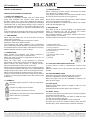
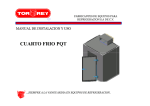
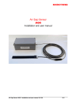
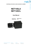
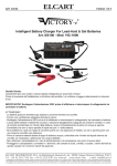
ART. 09/08500-00 ELCART PAGINA 1 DI 6 Manuale di istruzioni/Scheda tecnica PINZA AMPEROMETRICA DIGITALE MANUALE D’ISTRUZIONI 1. INFORMAZIONI DI SICUREZZA Pinza amperometrica digitale completamente portatile con display 3 1/2 digit LCD e funzione misurazione della resistenza di isolamento (unità di misurazione della resistenza di isolamento di 500V in opzione). Progettata secondo le norme IEC1010-1 IEC1010-2-032 relative ai requisiti di sicurezza per gli strumenti elettronici di misura con categoria di sovratensione (CAT II 1000V e CAT III 600V) ed inquinamento 2 ed i requisiti di sicurezza particolari per pinze amperometriche portatili per misure e prove elettriche. Rispettare e seguire tutte le avvertenze per la sicurezza del prodotto e le indicazioni d'uso per garantire una condizione operativa ottimale e sicura dell’ apparecchio. 1.1 ISTRUZIONI PRELIMINARI Quando si utilizza questo rilevatore, l’utente deve rispettare tutte le norme di sicurezza relative alla: Protezione contro i pericoli derivanti della corrente elettrica. Protezione contro abusi ed utilizzi erronei. Il pieno rispetto delle norme di sicurezza può essere garantito unicamente se si adoperano i puntali forniti. Se necessario, i puntali devono essere sostituiti con puntali identici o con gli stessi valori elettronici. I cavi di misura devono essere in buone condizioni. 1.2 DURANTE L’ USO Non superare mai i valori limite di protezione indicati nelle specifiche relative ad ogni gamma di misura. Quando lo strumento é connesso al circuito in esame non toccare mai alcun terminale, anche se inutilizzato. Quando il valore di scala da misurare è sconosciuto in precedenza, posizionare il selettore di marcia nella posizione massima. Prima di ruotare il selettore per cambiare di funzione, scollegare i puntali dal circuito in esame. Nell’effettuare le misure alla TV od al connettere i circuiti di potenza, ricordare sempre che possono esserci impulsi di alta tensione nei punti di prova, che potrebbero danneggiare il rilevatore. Non eseguire mai misurazioni di resistenza su circuiti sotto tensione. Fare sempre attenzione quando si eseguono lavori sotto tensione superiore ai 60VCC o 30VCA RMS. Tenere le dita dietro la protezione della sonda durante le misurazioni. 1.3 SIMBOLI Informazioni importanti sulla sicurezza, consultare il Manuale d’Uso. Possibile presenza di tensione pericolosa. Doppio isolamento (Classe di Protezione II). Senza pericolo per disconnettere i conduttori sotto tensione Terminale di terra. 1.4 MANUTENZIONE Prima di aprire il rilevatore, disconnettere sempre i puntali da qualsiasi sorgente di corrente elettrica. Se qualsiasi anomalia od errore vengono osservati, il rilevatore non dovrà essere utilizzato . L’ apparecchio dovrà essere assolutamente controllato da personale qualificato. Alloggiare correttamente la batteria nel proprio contenitore e fissare il coperchio in modo sicuro prima di utilizzare il rilevatore. Non utilizzare abrasivi o solventi per pulire il rilevatore, utilizzare unicamente un panno umido e un detergente delicato. 2. DESCRIZIONE Pinza amperometrica digitale completamente portatile con display 3 1/2 digit LCD per effettuare misure di tensione (in ca e cc), corrente alternata, resistenza, test di continuità e test di resistenza di isolamento. Completa protezione contro i sovraccarichi, indicazione di batteria scarica ed indicazione di condizione di superamento del limite (over range). La seguente tabella indica le funzioni di questa serie di rilevatori: 1. GANASCE 2. BARRIERA O INDICATORE TATTILE 3. INTERRUTTORE DATA HOLD 4. PRESA DI MISURA TEMPERATURA 5. COMMUTATORE ROTATIVO 6. DISPLAY LCD 7. CORDICELLA DI SICUREZZA 8. CONNETTORI DI INGRESSO 9. TRIGGER 1 2 9 3 4 5 6 8 7 2.1 SELETTORE DI MARCIA E FUNZIONE Il selettore rotativo é utilizzato per le funzioni di misura e gamme. Quando il selettore rotativo é in posizione OFF, il rilevatore non funziona. 2.2 GANASCE Rileva il valore della corrente alternata presente nel conduttore in esame. Premere il TRIGGER per ottenere l’ apertura graduale della ganasce. Quando si rilascia il dito che mantiene premuto il TRIGGER, i connettori si chiudono di nuovo. 2.3 INTERRUTTORE DATA HOLD (BLOCCO DATI) Premere il tasto HOLD per mantenere visualizzato il valore misurato. Ripremere il tasto DATA HOLD per cancellarlo. 2.4 CONNETTORI DI INGRESSO (INPUT JACKS) Questo rilevatore ha 3 connettori di ingresso protetti contro sovraccarichi e cortocircuiti nei limiti quantitativi indicati. Durante l'uso, connettere il puntale nero al jack d’ingresso COM e collegare il puntale rosso al jack VΩ. Il puntale rosso serve ad operare la funzione desiderata. Il connettore per ingresso EXT é utilizzato per riconoscere l’unità tester dell’isolamento durante le misure della resistenza di isolamento. ELCART DISTRIBUTION SPA via Michelangelo Buonarroti, 46 - 20093 Cologno Monzese (Milano) ITALY Tel. +39 02.25117310 Fax +39 02.25117610 sito internet: www.elcart.com e-mail: [email protected] La divulgazione dei dati contenuti in questa scheda è da ritenersi un servizio puramente informativo e non costituisce alcun vincolo da parte della Elcart in merito a prestazioni ed utilizzo del prodotto. The divulgation of data contained on this technical sheet are exclusively for informational reasons and establish no link on behalf of Elcart regard to thr performances and the usa of the product. La divulgacion de los datos contenidos en esta ficha son un servicio unicamente informativo y no constituyen ningun vinculo de parte de Elcart respecto a las prestaciones y uso del producto. ART. 09/08500-00 3. ISTRUZIONI OPERATIVE ELCART 3.1 MISURA DELLA CORRENTE 1. Selezionare tramite il commutatore rotativo la gamma di portata in A~ desiderata. Premere l’apposita leva (trigger) per l’apertura graduale della ganasce e bloccare un conduttore unicamente (Fig. 1). Le ganasce rileveranno la corrente alternata CA che circola nel conduttore in questione. 2. Quando si visualizza la figura “1”, questo indica una situazione di valori fuori specifica e bisogna selezionare la gamma superiore. NON CORRETTO Fig 1. PAGINA 2 DI 6 Manuale di istruzioni/Scheda tecnica CORRETTO 3.2 MISURA DELLA RESISTENZA DI ISOLAMENTO (unità di misurazione della resistenza di isolamento di 500V in opzione) 1. Connettere l’unità di misurazione della resistenza di isolamento VΩ, COM, EXT alla pinza amperometrica VΩ, COM, EXT. 2. Selezionare tramite il commutatore rotativo la posizione 2000MΩ. 3. Selezionare tramite il commutatore rotativo dell’unità di misura isolamento la posizione 2000MΩ. 4. Utilizzare i puntali dell’unità di misura isolamento e connetterli con il dispositivo sottoposto a misurazione (mettere l’impianto fuori tensione). 5. Selezionare la posizione ON dell’unità di misura della resistenza di isolamento. 6. Premere il tasto PUSH 500V; la spia LED rossa dei 500V si accenderà. Sullo schermo del rilevatore apparirà il valore di resistenza di isolamento. Se il rilevamento è inferiore a 19MΩ, cambiare il range del rilevatore e dell’unità di misura dell’isolamento a 20MΩ per aumentare la precisione di lettura. 7. Se l’unità di misurazione della resistenza di isolamento non é in uso, ricordarsi di spegnere sempre lo strumento (posizione power OFF) e sconnettere i puntali dal circuito. Questo permetterà di aumentare la vita della batteria e prevenire il rischio di scossa elettrica. 3.3 MISURA DI TENSIONE 1. Connettere il puntale nero al jack d’ingresso COM e collegare il puntale rosso al jack VΩ. 2. Posizionare il commutatore rotativo su V o V~ e connettere le altre estremità dei puntali in parallello al circuito da misurare. La polarità del collegamento del puntale rosso verrà indicata allo stesso tempo del valore di tensione durante la misura di tensione continua Vcc. 3. Quando si visualizza la figura “1”, questo indica una situazione di valori fuori specifica e bisogna selezionare la gamma superiore. 3.4 MISURA DI RESISTENZA 1. Connettere il puntale nero al jack d’ingresso COM e collegare il puntale rosso al jack VΩ. 2. Selezionare tramite il commutatore rotativo la portata in Ω e connettere l’altra estremità dei puntali sulla resistenza da misurare e leggerne il valore sul display. NOTA: 1. Se la resistenza da misurare supera il valore massimo del range selezionato o l’ingresso non é connesso, sul display apparirà l’indicazione di fuoriportata “1”. 2. Prima di effettuare misurazioni di resistenze inserite in un circuito, assicurarsi di avere tolto l’alimentazione a quest’ultimo e di averne scaricato le sue eventuali capacità interne. 3.5 PROVA DEI DIODI 1. Connettere il puntale nero al jack d’ingresso COM e collegare il puntale rosso al jack VΩ. (La polarità del puntale rosso é positiva “+”) 2. Collegate i puntali all’anodo del diodo da misurare e il puntale nero al catodo del diodo. La caduta di tensione approssimativa passante del diodo apparirà sul display. Se il collegamento è invertito, sul display apparirà solo “1”. 3.6 TEST DI CONTINUITA 1. Connettere il puntale nero al jack d’ingresso COM e collegare il puntale rosso al jack VΩ. (La polarità del puntale rosso é positiva “+”) 2. Selezionare tramite il commutatore rotativo la portata desiderata e connettere i puntali sul circuito in prova. Quando la resistenza di quest’ultimo risulta inferiore ai 100 Ω, verrà indicata la continuità tramite un segnale acustico continuo. ATTENZIONE: Per prevenire il rischio di scossa elettrica, assicurarsi che la sonda termocoppia sia stata scollegata prima di passare a un’altra funzione di misurazione. 3.8 MISURA DI FREQUENZA 1. Connettere il puntale nero al jack d’ingresso COM e collegare il puntale rosso al jack VΩ. 2. Selezionare tramite il commutatore rotativo la portata Hz e connettere i puntali sul circuito in prova. NOTA: 1. La lettura é possibile con tensione di valore efficace pari a 10V rms, ma non si garantisce l’accuratezza. 2. In ambienti rumorosi, è preferibile utilizzare del cavo schermato per misurare segnali molto piccoli. 4. SPECIFICHE La precisione é intesa per un periodo di calibrazione di durata annuale compreso tra 18℃ a 28℃ (64℉ a 82℉) sotto un’umidità relativa dell’80%. 4.1 DESCRIZIONE GENERALE Display: 3 1/2 digit LCD con indicazione di polarità automatica Terminali e messa a terra: 1000VCC o 750VAC (seno) Metodo di misura: Convertitore a doppia integrazione ELCART DISTRIBUTION SPA via Michelangelo Buonarroti, 46 - 20093 Cologno Monzese (Milano) ITALY Tel. +39 02.25117310 Fax +39 02.25117610 sito internet: www.elcart.com e-mail: [email protected] La divulgazione dei dati contenuti in questa scheda è da ritenersi un servizio puramente informativo e non costituisce alcun vincolo da parte della Elcart in merito a prestazioni ed utilizzo del prodotto. The divulgation of data contained on this technical sheet are exclusively for informational reasons and establish no link on behalf of Elcart regard to thr performances and the usa of the product. La divulgacion de los datos contenidos en esta ficha son un servicio unicamente informativo y no constituyen ningun vinculo de parte de Elcart respecto a las prestaciones y uso del producto. ELCART ART. 09/08500-00 Indicatore fuoriportata: Figura ”1” solo nel display Indicazione polarità: simbolo ”-” visualizzato per indicare la polarità negativa Temperatura di lavoro: 0℃ a 40℃ (32℉ a 104℉) Ambiente de stoccaggio: -10℃ a 50℃ (14℉ a 122℉) Alimentazione: batteria da 9V alcalina o al carboniozinco (6F22 o equivalente) Accessori: Manuale d’istruzioni, kit di puntali Indicazione batteria scarica: ”BAT” a sinistra dello schermo Dimensioni: 96(W) x 235(D) x 46(H) mm Peso: 330gr. (batteria inclusa) 4.2 CORRENTE ALTERNATA (CA) Gamma Risoluzione 1000A 1A 200A 0.1A Accuratezza ±2.5%della lettura ±5 cifre ±3.0%della lettura ±10 cifre Range di Frequenza: 50Hz a 60Hz Risposta: Media, Calibrata in rms di un'onda sinusoidale Protezione al sovraccarico: 1200A in 60 sec. Apertura max della pinza: Ø 50mm 4.3 MISURA RESISTENZA DI ISOLAMENTO (unità di misurazione della resistenza di isolamento di 500V in opzione) Gamma 20MΩ 2000MΩ Risoluz. Accuratezza Note 10kΩ ±2%della lettura ±2 cifre ±4%della lettura ±2 cifre ≤500MΩ 1MΩ ±5%della lettura ±2 cifre ≥500MΩ 4.4 TENSIONE ALTERNATA (VCA) Gamma 200V 750V Risoluzione 0.1V 1V PAGINA 3 DI 6 Manuale di istruzioni/Scheda tecnica Accuratezza ±1.0%della lettura ±5 cifre ±1.2%della lettura ±5 cifre 4.6 RESISTENZA Gamma 200Ω 2kΩ 20kΩ 200kΩ 2MΩ Risoluzione 0.1Ω 1Ω 10Ω 100Ω 1kΩ Protezione al sovraccarico: Tensione di circuito aperto: Accuratezza ±1.0% della lettura ±5 cifre ±1.0% della lettura ±8 cifre 250VCC o 250Vca RMS su tutti gli intervalli utilizzati 700mV 4.7 FREQUENZA Gamma 2kHz Risoluzione 1Hz Accuratezza ±2.0%della lettura ±5 cifre 5. ACCESSORI FORNITI CON LA PINZA Puntali Modello T3000 Batteria9V 6F22 o equivalente Manuale utente 6. SOSTITUZIONE DELLA BATTERIA Se la tensione non é più sufficiente per un corretto funzionamento dello strumento, il display visualizzerà la scritta “BAT”. Procedere quindi alla sostituzione con una nuova batteria di 9 V. AVVERTENZA Prima di tentare di aprire il coperchio della batteria, assicurarsi che i puntali siano scollegati dal circuito in esame per evitare il pericolo di scosse elettriche. AVVERTENZA Impedenza di ingresso: ≥9MΩ per tutte le gamme Protezione sovraccarichi: 1000VCC o 750VCA per tutte le gamme Range di Frequenza: (50Hz a 400Hz) / ≤600V (50Hz a 200Hz) / 750V Risposta: Media, Calibrata in rms di un'onda sinusoidale L’uso di questo apparecchio elettrico in un ambiente con forti interferenze elettromagnetiche o a radiofrequenza (approssimativamente 3V/m) può condizionare l’accuratezza della misurazione. 4.5 TENSIONE CONTINUA VCC Informazione agli utenti ex art. 26 D.Lgs. 49/2014 Il simbolo riportato sull’apparecchiatura (Allegato IX D.Lgs. 49/2014) indica che il rifiuto deve essere oggetto di “raccolta separata” e che è stato immesso sul mercato, in Italia, dopo il 31/12/2010. Pertanto, l’utente dovrà conferire (o far conferire) il rifiuto ai centri di raccolta differenziata predisposti dalle amministrazioni locali, oppure consegnarlo al rivenditore contro acquisto di una nuova apparecchiatura di tipo equivalente. L’utente ha dunque un ruolo attivo: la raccolta differenziata del rifiuto e le successive operazioni di trattamento, recupero e smaltimento favoriscono la produzione di apparecchiature con materiali riciclati e limitano gli effetti negativi sull’ambiente e sulla salute eventualmente causati da una gestione impropria del rifiuto. Nel caso di RAEE di piccolissime dimensioni (<25 cm), l’utente ha diritto al conferimento gratuito, senza obbligo di contestuale acquisto, ai distributori al dettaglio la cui superficie di vendita specializzata eccede i 400 mq. Gamma 2V 20V 200V 1000V Risoluzione 1mV 10mV 0.1V 1V Accuratezza ±0.5% della lettura ±3 cifre ±0.8% della lettura ±3 cifre Impedenza di ingresso: ≥9MΩ Protezione sovraccarichi: 250Vrms AC per gamma 200mV, 1000VCC o 750VCA per le altre gamme IMPORTATO E DISTRIBUITO DA ELCART DISTRIBUTION SPA Via Michelangelo Buonarroti, 46 20093 COLOGNO MONZESE (MI) ITALY www.elcart.com - [email protected] Made in China ELCART DISTRIBUTION SPA via Michelangelo Buonarroti, 46 - 20093 Cologno Monzese (Milano) ITALY Tel. +39 02.25117310 Fax +39 02.25117610 sito internet: www.elcart.com e-mail: [email protected] La divulgazione dei dati contenuti in questa scheda è da ritenersi un servizio puramente informativo e non costituisce alcun vincolo da parte della Elcart in merito a prestazioni ed utilizzo del prodotto. The divulgation of data contained on this technical sheet are exclusively for informational reasons and establish no link on behalf of Elcart regard to thr performances and the usa of the product. La divulgacion de los datos contenidos en esta ficha son un servicio unicamente informativo y no constituyen ningun vinculo de parte de Elcart respecto a las prestaciones y uso del producto. ART. 09/08500-00 ELCART DIGITAL CLAMP METER OPERATOR’S INSTRUCTION MANUAL 1. SAFETY INFORMATION The meter is completely portable, LCD, 3 1/2 digit clamp meter with insulation test function (with option 500V insulation tester unit). It has been designed according to IEC1010-1 IEC1010-2-032 concerning electronic measuring instruments with an overvoltage category (CAT II 1000V & CAT III 600V) and pollution 2 and safety requirements for hand-held current clamps for electrical measurement and test. Follow all safety and operating instructions to ensure that the meter is used safely and is kept in good operating condition. 1.1 PRELIMINARY When using this meter, the user must observe all normal safety rules concerning: Protection against the dangers of electronic current. Protection of the meter against misuse. Full compliance with safety standards can be guaranteed only if used with test leads supplied. If necessary, they must be replaced with the same model or same electronic ratings. Measuring leads must be in good condition. 1.2 DURING USE Never exceed the protection limit values indicated in specifications for each range of measurement. When the meter is linked to measurement circuit, do not touch unused terminals. When the value scale to be measured is unknown beforehand, set the range selector at the highest position. Before rotating the range selector to change function, disconnect test leads from the circuit under test. When carrying out measurements on TV or switching power circuits always remember that there may be high amplitude voltage pulses at test points, which can damage the meter. Never perform resistance measurements on live circuits. Always is careful when working with voltage above 60VDC or 30VAC rms. Keep fingers behind the probe barriers while measuring. 1.3 SYMBOLS Important safety information, refer to the operating manual. PAGINA 4 DI 6 Manuale di istruzioni/Scheda tecnica Dangerous voltage may be present. Double insulation (Protection class II). Application around and removal from HAZARDOUS LIVE conductors is permitted. Earth ground. 1.4 MAINTENANCE Before opening the meter, always disconnect test leads from all sources of electric current. If any faults or abnormalities are observed, the meter cannot be used anymore and it has to be checked out. Never use the meter unless the back cover and the battery cover are in place and fastened fully. Do not use abrasives or solvents on the meter, use a damp cloth and mild detergent only. 2. DESCRIPTION This meter is one of a series portable 3 1/2 digital clamp meter for measuring DC and AC Voltage, AC current, resistance, continuity test and insulation test. Full overload protection, Low battery indication and overrange indication are providing. Following table shows function of the series of clamp meter: 1. TRANSFORMER JAWS 2. BARRIER OR TACTILE INDICATOR 3. DATA HOLD SWITCH 4. TEMPERATURE MEASURING SOCKET 5. ROTARY SWITCH 6. LCD DISPLAY 7. DROP-PROOF WRIST STRAP 8. INPUT JACKS 9. TRIGGER 1 2 9 3 4 5 6 8 7 2.1 FUNCTION AND RANGE SELECTOR A rotary switch is used to measurement functions and ranges. When the switch is set to OFF position, the meter does not operate. 2.2 TRANSFORMER JAWS Pick up the AC current flowing through the conductor. Press the TRIGGER to open the transformer jaws. When the finger press on the TRIGGER is released, the jaws will close again. 2.3 DATA HOLD Depress HOLD Button Switch to toggle in and out of the Data Hold mode. Releasing Data Hold mode again press the button. 2.4 INPUT JACKS This meter has three input jacks that are protected against overload to the limits shown. During use connect the black test lead to COM jack and connect red test lead to VΩ jack. The red test lead is depended on function selected. The EXT jack is used for accept insulation tester unit EXT banana Plugs, when measurement insulation resistance. ELCART DISTRIBUTION SPA via Michelangelo Buonarroti, 46 - 20093 Cologno Monzese (Milano) ITALY Tel. +39 02.25117310 Fax +39 02.25117610 sito internet: www.elcart.com e-mail: [email protected] La divulgazione dei dati contenuti in questa scheda è da ritenersi un servizio puramente informativo e non costituisce alcun vincolo da parte della Elcart in merito a prestazioni ed utilizzo del prodotto. The divulgation of data contained on this technical sheet are exclusively for informational reasons and establish no link on behalf of Elcart regard to thr performances and the usa of the product. La divulgacion de los datos contenidos en esta ficha son un servicio unicamente informativo y no constituyen ningun vinculo de parte de Elcart respecto a las prestaciones y uso del producto. ELCART ART. 09/08500-00 3. OPERATING INSTRUCTION 3.1 MEASURING CURRENT 1. Set the rotary switch at desired A~ range position. Press the trigger to open the transformer jaws and clamp onto one conductor only (Fig.1), The transformer jaws pick up the AC current flowing through the conductor. 2. When only the figure “1” displayed, it indicates overrange situation and the higher range have to be selected. WRONG PAGINA 5 DI 6 Manuale di istruzioni/Scheda tecnica Fig 1. CORRECT 3.2 INSULATION TEST (Option 500V insulation tester unit) 1. Connect the insulation tester unit VΩ, COM, EXT threebanana plugs to the clamp meter VΩ, COM, EXT. 2. Set the rotary switch of clamp meter at 2000MΩ position. 3. Set the insulation tester unit range switch to the 2000MΩ position. 4. Uses the insulation tester unit of the test leads connects its L, E input connect to being tested installations. (Test installation's must be power OFF) 5. Set the insulation tester power switch to the ON position. 6. Depress the PUSH 500V push-push switch; the 500V on red LED lamp will light. Clamp meter display reading is the insulation resistance value. If the reading is below 19MΩ change clamp meter and insulation tester unit to 20MΩ range, can be increasing the accuracy. 7. If the insulation tester unit is not use, the power switch must shift to power OFF position, and the test leads must leave the E. L input connect. That can be increase battery life and prevent electrical shock hazard. 3.3 MEASURING VOLTAGE 1. Connect the black test lead to the COM jack and the red test lead to the VΩ jack. 2. Set the rotary switch at the desired V or V~ range position and connect test leads across the source or load under measurement. The polarity of the red lead connection will be indicated along with the voltage value when making DC voltage measurement. 3. When only the figure“ 1 ”is displayed, it indicates over range situation and the higher range has to be selected. 3.4 MEASURING RESISTANCE 1. Connect the black test lead to the COM jack and the red test lead to the VΩ jack. 2. Set the rotary switch at desired Ω position and connect test leads across the resistor under measurement. NOTE: 1. If the resistance being measured exceeds the maximum value of the range selected or the input is not connected, an over range indication “1” will be displayed. 2. When checking in - circuit resistance, be sure the circuit under test has all power removed and that all capacitors have been discharged fully. 3.5 TESTING DIODE 1. Connect the black test lead to the COM jack and the red test lead to the VΩ jack. (The polarity of red lead is “+”) 2. Set the rotary switch at position and connect red lead to the anode, black lead to the cathode of the diode under testing. The meter will show the approx. forward voltage of the diode. If the lead connection is reversed, only figure “1” displayed. 3.6 CONTINUITY TEST 1. Connect the black test lead to the COM jack and the red test lead to the VΩ jack. (The polarity of the red lead is positive“ + ”) 2. Set the rotary switch at position and connect test leads across two points of the circuit under testing. If continuity exists (i.e., resistance less than about 100Ω), built -in buzzer will sound. WARNING To avoid electric shock, be sure the thermocouple has been removed before changing to another function measurement. 3.8 MEASURING FREQUENCY 1. Connect the black test lead to the COM jack and the red test lead to the VΩ jack. 2. Set the rotary switch at Hz position and connect test leads across the source or load under measurement. NOTE: 1. Reading is possible at input voltage above 10V rms, but the accuracy is not guaranteed. 2. In noisy environment, it is preferable to use shield cable for measuring small signal. 4. SPECIFICATIONS Accuracy is specified for a period of one year after calibration and at 18℃ to 28℃ ( 64℉ to 82℉) with relative humidity to 80%. 4.1 GENERAL Display: 3 1/2 digit LCD, with automatic polarity indication Terminals and earth ground: 1000V dc or 750V rms ac (sine) Measuring Method: Dual-slope integration A-D converter Over range Indication: ”1” Figure only in the display Polarity indication: ”-”displayed for negative polarity Operating Temperature: 0℃ to 40℃ (32℉ to 104℉) Storage Environment: -10℃ to 50℃(14℉ to 122℉) Power: 9V alkaline or carbon-zinc battery (6F22 or equivalent) Accessories: Operating manual, set of test leads Low Battery Indication: ”BAT” to left of display Dimension: 96(W)x235(D)x46(H) mm Weight: 330gr. (including battery) ELCART DISTRIBUTION SPA via Michelangelo Buonarroti, 46 - 20093 Cologno Monzese (Milano) ITALY Tel. +39 02.25117310 Fax +39 02.25117610 sito internet: www.elcart.com e-mail: [email protected] La divulgazione dei dati contenuti in questa scheda è da ritenersi un servizio puramente informativo e non costituisce alcun vincolo da parte della Elcart in merito a prestazioni ed utilizzo del prodotto. The divulgation of data contained on this technical sheet are exclusively for informational reasons and establish no link on behalf of Elcart regard to thr performances and the usa of the product. La divulgacion de los datos contenidos en esta ficha son un servicio unicamente informativo y no constituyen ningun vinculo de parte de Elcart respecto a las prestaciones y uso del producto. ELCART ART. 09/08500-00 4.7 FREQUENCY 4.2 AC CURRENT Range Resolution 1000A 1A 200A PAGINA 6 DI 6 Manuale di istruzioni/Scheda tecnica 0.1A Accuracy ±2.5% of rdg ±5 digits Range 2kHz Resolution 1Hz Accuracy ±2.0% of rdg ±5 digits ±3.0% of rdg ±10 digits Frequency Range: 50Hz to 60Hz Response: Average, Calibrated in rms of sine wave Overload protection: 1200A within 60 seconds Jaw Opening: Ø50mm 5. ACCESSORIES COME WITH THE CLAMP METER Test Leads Model: T3000 Battery 9V 6F22 or equivalent Operation Manual 4.3 INSULATION TEST (With option 500V insulation tester unit) 6. BATTERY REPLACEMENT If the sign “BAT” appears on the LCD display, it indicates that battery should be replaced. Remove the battery cover of case. Replace the exhausted battery with a new one. Range 20MΩ Resolution 10kΩ 2000MΩ 1MΩ Accuracy ±2% of rdg ±2 digits ±4% of rdg ±2 digits ±5% of rdg ±2 digits Note ≤500MΩ ≥500MΩ 4.4 AC VOLTAGE Range 200V 750V Resolution 0.1V 1V Accuracy ±1.0% of rdg ±5 digits ±1.2% of rdg ±5 digits Input Impedance: ≥9MΩ on all ranges Overload protection: 1000V DC or 750V AC on all ranges Frequency Range: (50Hz to 400Hz) / ≤600V (50Hz to 200Hz) / 750V Response: Average, calibrated in rms of sine wave 4.5 DC VOLTAGE Range 2V 20V 200V 1000V Resolution 1mV 10mV 0.1V 1V WARNING Before attempting to open the battery cover, be sure that test leads have been disconnected from measurement circuits to avoid electric shock hazard. WARNING Using this appliance in an environment with a strong radiated radio-frequency electromagnetic field (approximately 3V/m) may influence its measuring accuracy. Accuracy ±0.5% of rdg ±3 digits ±0.8% of rdg ±3 digits Input Impedance: ≥9MΩ Overload protection: 250Vrms AC for 200mV range 1000V DC or 750V AC for other range 4.6 RESISTANCE Range 200Ω 2kΩ 20kΩ 200kΩ 2MΩ Resolution 0.1Ω 1Ω 10Ω 100Ω 1kΩ Accuracy ±1.0% of rdg ±5 digits ±1.0% of rdg ±8 digits Overload protection:250VDC or 250Vrms AC on all ranges Open circuit voltage: 700mV User information ex art. 26 D. 49/2014 The symbol labelled on the appliance (Annex IX D. 49/2014) indicates that the rubbish is subject to “separate collection” and it has been placed on the Italian market after the December 31, 2010. The user must therefore assign or (have collected) the rubbish to a treatment facility according to indications by the local administration, or hand it over to the reseller in exchange for an equivalent new product. The separate collection of the rubbish and the subsequent treatment, recycling and disposal operations encourage the production of appliances made with recycled materials and reduce negative effects on health and the environment caused by improper treatment of rubbish. In the case of very small WEEE (no external dimension more than 25 cm), the user is eligible to get free of charge assignation to retail shops with sales areas relating to EEE of at least 400 m². IMPORTED AND DISTRIBUTED BY: ELCART DISTRIBUTION SPA Via Michelangelo Buonarroti, 46 20093 COLOGNO MONZESE (MI) ITALY www.elcart.com - [email protected] Made in China ELCART DISTRIBUTION SPA via Michelangelo Buonarroti, 46 - 20093 Cologno Monzese (Milano) ITALY Tel. +39 02.25117310 Fax +39 02.25117610 sito internet: www.elcart.com e-mail: [email protected] La divulgazione dei dati contenuti in questa scheda è da ritenersi un servizio puramente informativo e non costituisce alcun vincolo da parte della Elcart in merito a prestazioni ed utilizzo del prodotto. The divulgation of data contained on this technical sheet are exclusively for informational reasons and establish no link on behalf of Elcart regard to thr performances and the usa of the product. La divulgacion de los datos contenidos en esta ficha son un servicio unicamente informativo y no constituyen ningun vinculo de parte de Elcart respecto a las prestaciones y uso del producto.