1
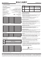
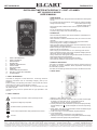
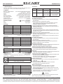
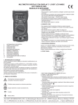
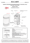
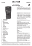
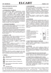
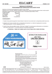
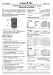
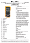
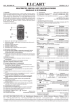
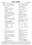
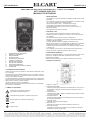
ELCART
ART. 09/09230-00
Manuale di istruzioni/Scheda tecnica
PAGINA 1 DI 6
MULTIMETRO DIGITALE CON DISPLAY 3 ½ DIGIT LCD NIMEX
ART. 09/09230-00 NI 9230
MANUALE DI ISTRUZIONI
3. MANUTENZIONE
- Prima di aprire il coperchio posteriore, scollegate i puntali da ogni circuito
alimentato
- Per mantenere la protezione anti scariche elettriche, sostituite il fusibile
con uno nuovo delle stesse proprietà elettriche:
250mA/250V (Quick Acting) - 10A/250V (Quick Acting)
- Non utilizzate lo strumento senza il coperchio posteriore
- Periodicamente strofinate lo strumento con un panno umido e un
detergente delicato
- Non utilizzate panni abrasivi o solventi
4. DURANTE L'USO
- Non superate i limiti di protezione indicate su questo manuale
- Quando il multimetro è collegato a un circuito, non toccate i terminali
non utilizzati
- Non misurate tensioni superiori a 600V in Category III
- Nel caso in cui non sappiate quale gamma di misurazione utilizzare,
scegliete la più alta possibile
- Prima di cambiare funzione, scollegate i puntali dal circuito
- Nel caso di misurazioni su TV o alimentatori, ricordatevi che ci potrebbero
essere tensioni di picco che potrebbero danneggiare lo strumento
- Prestate sempre attenzione nel caso in cui la tensione superi i 60VCC
o i 30VCA rms
- Non collegate lo strumento a un circuito alimentato nelle funzioni di
misura di corrente, resistenza, test diodo, test continuità
1.
2.
3.
4.
5.
6.
7.
8.
9.
10.
11.
INFORMAZIONI DI SICUREZZA
SIMBOLI DI SICUREZZA
MANUTENZIONE
DURANTE L'USO
DESCRIZIONE GENERALE
PANNELLO FRONTALE
SPECIFICHE TECNICHE
SPECIFICHE GENERALI
ISTRUZIONI OPERATIVE
SOSTITUZIONE BATTERIA & FUSIBILE
ACCESSORI
1. INFORMAZIONI DI SICUREZZA
Questo strumento di misura, adatto per misurazioni multifunzione è pratico e compatto.
Progettato per seguire la direttiva IEC61010-1 e CAT II 600V, sovraten sione e doppio isolamento. La struttura compatta è resistente ai rischi di
rottura dovuti a eventuali cadute.
Per ottenere prestazioni ottimali, la preghiamo di leggere con attenzione
questo manuale di istruzioni prima del collegamento, dell’installazione e
della messa in funzione di questo prodotto.
Conservi il manuale per future consultazioni.
Questo strumento di misura è adatto all’uso nelle scuole, nei laboratori o
per misurazioni hobbystiche.
2. SIMBOLI DI SICUREZZA
Informazione di sicurezza importante.
Consultate il manuale di istruzioni.
Potrebbe essere presente una tensione pericolosa.
Doppio isolamento. Classe di protezione (II).
Fusibile
Massa (Terra)
5. DESCRIZIONE GENERALE
Questo è un multimetro digitale 3 ½ LCD per misurazioni di VCC e VCA,
corrente CC, resistenza, test diodi, temperatura, test continuità.
Alimentazione a batteria.
Dotato di retroilluminazione per l’utilizzo in ambienti poco illuminati.
6. PANNELLO FRONTALE
1- Display 3 ½ digit, (2000 count) LCD
2- Pulsante “BACK LIGHT”
Premendo questo tasto, attiverete la retroilluminazione, dopo circa 10"
la lampadina si spegnerà automaticamente; premendo di nuovo, si
riaccenderà
3- Pulsante ‘HOLD”
Premendo questo tasto, il display visualizzerà l’ultima lettura misurata
con accanto il simbolo “ H ”
4- Interruttore Rotativo
Questa manopola è utilizzata per selezionare la funzione e la gamma
di misurazione desiderata
5- Terminale “COM”
Terminale per il puntale nero (negativo)
6- Terminale “10A”
Terminale per il puntale rosso nella misurazione corrente 10A
7-Terminale “VΩmAµA”
Terminale per il puntale rosso (positivo) per misurazione di tensione,
resistenza e corrente (eccetto 10A).
ELCART DISTRIBUTION SPA via Michelangelo Buonarroti, 46 - 20093 Cologno Monzese (Milano) ITALY
Tel. +39 02.25117310 Fax +39 02.25117610 sito internet: www.elcart.com
e-mail: [email protected]
La divulgazione dei dati contenuti in questa scheda è da ritenersi un servizio puramente informativo e non costituisce alcun vincolo da parte della Elcart in merito a prestazioni ed utilizzo del prodotto.
The divulgation of data contained on this technical sheet are exclusively for informational reasons and establish no link on behalf of Elcart regard to thr performances and the usa of the product.
La divulgacion de los datos contenidos en esta ficha son un servicio unicamente informativo y no constituyen ningun vinculo de parte de Elcart respecto a las prestaciones y uso del producto.
ELCART
ART. 09/09230-00
7. SPECIFICHE TECNICHE
La precisione è specificata per un periodo di un anno dalla calibrazione
e per un utilizzo ad una temperatura di 18°÷28°C (64°÷82°F) con umidità
relativa dell’ 80%.
8. SPECIFICHE GENERALI
Massima tensione tra i terminali:
CAT II 600V e la terra
Protezione fusibile:
F 250mA/250V - 10A/250V
Alimentazione:
batteria 9V, NEDA 1604 or 6F22
Display:
LCD 2000 counts, aggiornato 2-3volte al sec.
Metodo di misurazione:
Dual-slope integration A/D converter
Indicazione sovraccarico:
“1” visualizzato sul display
Indicatore Polarità:
“-“ visualizzato per indicare il negativo
Temperatura di utilizzo:
0° ÷ 40°C
Temperatura di conservazione:
-10° ÷ 50°C
Indicatore batteria scarica:
“
” visualizzato sul display
Dimensioni:
140x67x30 mm
Peso:
112 gr. circa
Tensione VCC
RANGE
RISOLUZIONE
PRECISIONE
200mV
100µV
± (0.5% of rdg ± 2digits)
2V
1mV
± (0.5% of rdg ± 2digits)
20V
10mV
± (0.5% of rdg ± 2digits)
200V
100mV
± (0.5% of rdg ± 2digits)
600V
1V
± (0.8% of rdg ± 2digits)
*Protezione sovraccarico:
250Vrms per gamma 200mV
600VCC o rms CA per le altre gamme
Corrente CC
RANGE
RISOLUZIONE
PRECISIONE
200µA
0,1µA
± (1% of rdg ± 2digits)
2mA
1µA
± (1% of rdg ± 2digits)
20mA
10µA
± (1% of rdg ± 2digits)
200mA
100µA
± (1.5% of rdg ± 2digits)
10A
10mA
± (3% of rdg ± 2digits)
*Protezione sovraccarico:
F250mA/250V fuse - F10A/250V fuse
Tensione VCA
RANGE
RISOLUZIONE
PRECISIONE
200V
100mV
± (1.2% of rdg + 10digits)
600V
1V
± (1.2% of rdg + 10digits)
*Protezione sovraccarico:
600VCC o rms. CA per le altre gamme
*Gamma di Frequenza:
40Hz ÷ 400Hz
*Risposta: Media, calibrazione in valore efficace di un’onda sinusoidale
Diodi e Continuità
RANGE
PAGINA 2 DI 6
Manuale di istruzioni/Scheda tecnica
FUNZIONE
Visualizza il valore approssimativo della caduta di tensione
diretta del diodo
Il cicalino incorporato suona se la resistenza è minore di 100Ω
*Protezione sovraccarico:
250VCC o rms. CA
Resistenza
Temperatura
RANGE
RISOLUZIONE
TEST RANGE
PRECISIONE
°C
1°C
-20°C ÷ 0°C
0°C ÷ 400°C
400°C ÷ 1000°C
±(10% of rdg±2digits)
±(1.0% of rdg±3digits)
±2.0% of rdg
°F
1°F
-4°F ÷ 32°F
32°F ÷ 752°F
752°F ÷ 1832°F
±(10% of rdg±2digits)
±(1.0% of rdg±3digits)
±2.0% of rdg
9. ISTRUZIONI OPERATIVE
Misurazione Tensione VCC
1. Inserite il puntale rosso nel terminale “V.Ω.mA” e il nero nel terminale “COM”
2. Ruotate la manopola sulla gamma di misurazione VCC.
Nel caso in cui non sappiate quale gamma di misurazione utilizzare,
scegliete la più alta possibile
3. Collegate i puntali all’apparecchiatura o al circuito da misurare
4. Il valore misurato verrà visualizzato sul display LCD.
Sul display sarà indicata la polarità della misura
Misurazione Corrente CC
1. Inserite il puntale rosso nel terminale “V.Ω.mA” e il puntale nero nel
terminale “COM” (per misurazioni comprese tra 250mA e 10A,
per misurazioni superiori a 10A utilizzate il terminale corrispondente)
2. Ruotate la manopola sulla gamma di misurazione DCA
3. Collegate i puntali in serie all’apparecchiatura o al circuito da misurare
4. Il valore misurato verrà visualizzato sul display LCD.
Sul display sarà indicata la polarità della misura
Misurazione Tensione VCA
1. Inserite il puntale rosso nel terminale “V.Ω.mA” e il nero nel terminale “COM”
2. Ruotate la manopola sulla gamma di misurazione ACV
3. Collegate i puntali all’apparecchiatura o al circuito da misurare
4. Il valore misurato verrà visualizzato sul display LCD
Misurazione Resistenza
1. Inserite il puntale rosso nel terminale “V.Ω.mA” e il nero nel terminale “COM”
2. Ruotate la manopola sulla gamma di misurazione ”Ω”.
3. Collegate i puntali in serie all’apparecchiatura o al circuito da misurare
4. Se la resistenza da misurare è collegata a un circuito, togliete l’alimentazione
al circuito e scaricate tutti i condensatori prima di collegare i puntali
Test Diodi
1. Inserite il puntale rosso nel terminale “V.Ω.mA” e il nero nel terminale “COM”
2. Ruotate la manopola sulla gamma di misurazione “
”
3. Collegate il puntale rosso all’anodo del diodo e quello nero al catodo.
La tensione di caduta del diodo verrà visualizzata sul display.
Se il collegamento è inverso, verrà visualizzato il simbolo “1”
Test Continuità
1. Inserite il puntale rosso nel terminale “V.Ω.mA” e il nero nel terminale “COM”
2. Ruotate la manopola sulla gamma di misurazione “
”.
3. Collegate i puntali all’apparecchiatura o al circuito da misurare
Se viene rilevata la continuità il buzzer emetterà un suono
Misurazione Temperatura
1. Per misure in °C, ruotate la manopola sulla gamma di misurazione “°C”
Per misure in °F, ruotate la manopola sulla gamma di misurazione “°F”
Unendo tra loro i puntali, lo strumento visualizzerà la temperatura ambientale
2. Collegate il puntale rosso della termocoppia al terminale “V.Ω.mA” e
il puntale nero al terminale “COM”
3. Leggete il valore misurato sul display
RANGE
RISOLUZIONE
PRECISIONE
200Ω
0,1Ω
± (0.8% of rdg ± 3digits)
2KΩ
1Ω
± (0.8% of rdg ± 2digits)
Attenzione
Per evitare scosse elettriche, assicuratevi di aver disconnesso la termocoppia
prima di cambiare funzione con la manopola.
20KΩ
10Ω
± (0.8% of rdg ± 2digits)
200KΩ
100Ω
± (0.8% of rdg ± 2digits)
2MΩ
1KΩ
± (1.0% of rdg ± 2digits)
*Protezione sovraccarico:
250VCC o CA rms per tutte le gamme
*Massima tensione circuito aperto:
3.2V
ELCART DISTRIBUTION SPA via Michelangelo Buonarroti, 46 - 20093 Cologno Monzese (Milano) ITALY
Tel. +39 02.25117310 Fax +39 02.25117610 sito internet: www.elcart.com
e-mail: [email protected]
La divulgazione dei dati contenuti in questa scheda è da ritenersi un servizio puramente informativo e non costituisce alcun vincolo da parte della Elcart in merito a prestazioni ed utilizzo del prodotto.
The divulgation of data contained on this technical sheet are exclusively for informational reasons and establish no link on behalf of Elcart regard to thr performances and the usa of the product.
La divulgacion de los datos contenidos en esta ficha son un servicio unicamente informativo y no constituyen ningun vinculo de parte de Elcart respecto a las prestaciones y uso del producto.
ELCART
ART. 09/09230-00
Manuale di istruzioni/Scheda tecnica
PAGINA 3 DI 6
10. SOSTITUZIONE BATTERIA E FUSIBILE
Se il simbolo ”
” apparirà sul display, significa che dovete sostituire la batteria perché scarica.
Il fusibile necessita raramente di sostituzione e nella maggior parte dei casi la rottura è dovuta a un errore compiuto durante la misurazione dell’utente.
Per sostituire batteria e fusibile (250mA/250V e 10A/250V) rimuovete le 2 viti dal lato inferiore dello strumento.
Sostituite la batteria e il fusibile e richiudete il coperchio.
Attenzione
Prima di rimuovere il coperchio delle batterie, assicuratevi che i puntali non siano collegati al circuito da misurare.
Prima di utilizzare di nuovo lo strumento, assicuratevi di aver chiuso completamente il coperchio delle batterie.
11. ACCESSORI
- Manuale di istruzioni
- Coppia di puntali
- Termocoppia
- Batteria 9V
Informazioni agli utenti
Il simbolo riportato sull’apparecchiatura indica che il rifiuto deve essere oggetto di
“raccolta separata”.
Pertanto, l’utente dovrà conferire (o far conferire) il rifiuto ai centri di raccolta differenziata
predisposti dalle amministrazioni comunali, oppure consegnarlo al rivenditore contro
acquisto di una nuova apparecchiatura di tipo equivalente.
La raccolta differenziata del rifiuto e le successive operazioni di trattamento, recupero
e smaltimento favoriscono la produzione di apparecchiature con materiali riciclati e
limitano gli effetti negativi sull’ambiente e sulla salute eventualmente causati da una
gestione impropria del rifiuto.
Lo smaltimento abusivo del prodotto da parte dell’utente comporta l’applicazione delle
sanzioni amministrative di cui l’articolo 50 e seguenti del D. Lgs. N° 22/1997.
IMPORTATO E DISTRIBUITO DA
ELCART DISTRIBUTION SPA
Via Michelangelo Buonarroti, 46
20093 COLOGNO MONZESE (MI)
ITALY
www.elcart.com - [email protected]
Made in China
Informazione agli utenti ex art. 26 D.Lgs. 49/2014
Il simbolo riportato sull’apparecchiatura (Allegato IX D.Lgs. 49/2014) indica che il rifiuto deve essere oggetto di “raccolta
separata” e che è stato immesso sul mercato, in Italia, dopo il 31/12/2010.
Pertanto, l’utente dovrà conferire (o far conferire) il rifiuto ai centri di raccolta differenziata predisposti dalle amministrazioni
locali, oppure consegnarlo al rivenditore contro acquisto di una nuova apparecchiatura di tipo equivalente.
L’utente ha dunque un ruolo attivo: la raccolta differenziata del rifiuto e le successive operazioni di trattamento, recupero e
smaltimento favoriscono la produzione di apparecchiature con materiali riciclati e limitano gli effetti negativi sull’ambiente
e sulla salute eventualmente causati da una gestione impropria del rifiuto.
Nel caso di RAEE di piccolissime dimensioni (<25 cm), l’utente ha diritto al conferimento gratuito, senza obbligo di
contestuale acquisto, ai distributori al dettaglio la cui superficie di vendita specializzata eccede i 400 mq.
IMPORTATO E DISTRIBUITO DA
ELCART DISTRIBUTION SPA
Via Michelangelo Buonarroti, 46
20093 COLOGNO MONZESE (MI)
ITALY
www.elcart.com - [email protected]
Made in China
ELCART DISTRIBUTION SPA via Michelangelo Buonarroti, 46 - 20093 Cologno Monzese (Milano) ITALY
Tel. +39 02.25117310 Fax +39 02.25117610 sito internet: www.elcart.com
e-mail: [email protected]
La divulgazione dei dati contenuti in questa scheda è da ritenersi un servizio puramente informativo e non costituisce alcun vincolo da parte della Elcart in merito a prestazioni ed utilizzo del prodotto.
The divulgation of data contained on this technical sheet are exclusively for informational reasons and establish no link on behalf of Elcart regard to thr performances and the usa of the product.
La divulgacion de los datos contenidos en esta ficha son un servicio unicamente informativo y no constituyen ningun vinculo de parte de Elcart respecto a las prestaciones y uso del producto.
ELCART
ART. 09/09230-00
Manuale di istruzioni/Scheda tecnica
PAGINA 4 DI 6
DIGITAL MULTIMETER WITH DISPLAY 3 ½ DIGIT LCD NIMEX
ART. 09/09230-00 NI 9230
USER'S MANUAL
3. MAINTENANCE
- Before opening the case, always disconnect test leads from all energized
circuits.
- For continue protection against fire, replace fuse only with the specified
voltage and current rating:
250mA/250V (Quick Acting)
10A/250V (Quick Acting)
- Never use the meter unless the back cover is in place and fastened
completely.
- Do not use abrasives or solvents on the meter.
To clean it using a damp cloth and mild detergent only.
4. DURING USE
1.
2.
3.
4.
5.
6.
7.
8.
9.
10.
11.
SAFETY INFORMATION
SAFETY SYMBOLS
MAINTENANCE
DURING USE
GENERAL DESCRIPTION
FRONT PANEL
SPECIFICATIONS
GENERAL
OPERATING INSTRUCTIONS
BATTERY & FUSE REPLACEMENT
ACCESSORIES
- Never exceed the protection limit values indicated in specifications for
each range of measurement.
- When the meter is linked to measurement circuit, do not touch unused
terminals.
- Never use the meter to measure voltages that might exceed 600V
above earth ground in category III installations.
- When the value scale to be measured is unknown beforehand, set the
range selector at the highest position.
- Before rotating the range selector to change functions, disconnect test
leads from the circuit under test.
- When carrying out measurements on TV or switching power circuits
always remember that there may be high amplitude voltages pulses at
test points, which can damage the meter.
- Always careful when working with voltages above 60VDC or 30VAC rms
Keep fingers behind the probe barriers.
- When making voltage measurements with test leads.
Never perform resistance measurements on live circuits.
5. GENERAL DESCRIPTION
The meter is a handheld 3 ½ digital multi meter for measuring DC and
AC voltage, DC current, resistance, diode, temperature and continuity
test with battery operated.
The meter has the back light function that is used in the dark environment.
6. FRONT PANEL
1. SAFETY INFORMATION
This Meter is designed to meet IEC61010-1 concerning electronic
measuring instruments with an overvoltage category (CAT II) and
pollution 2.
Follow all safety and operating instructions to ensure that the meter is
used safely and is kept in good operating condition.
Full compliance with safety standards can be guaranteed only with
test leads supplied.
If necessary, they must be replaced with the type specified in this
manual.
2. SAFETY SYMBOLS
Important safety information, refer to operating manual
Dangerous voltage may be present
Double Insulation (Protection class II)
Fuse must be replaced with rating specified in the manual
Ground
1 Display 3 ½ digit, (2000 count) LCD.
2 “BACK LIGHT” push button. When this button is pushed, the back light
of display is on. After about 10 sec., the backlight is self-off.
The backlight is on again, just push this button once.
3 "HOLD” push button. When this button is pushed, the display will keep
the last reading and “ H ” symbol will appear on the LCD until pushing
it again.
4 Rotary Switch. This switch is used to select functions and desired ranges
as well as to turn on/off the meter.
5 “COM” Jack. Plug in connector for Black (negative) test lead.
6 “10A” input terminal.
Plug in connector for red test lead for 10A measurement.
7 “VΩmAμA” Jack. Plug in connector for red (positive) test lead for voltage,
resistance and current (except 10A) measurements.
ELCART DISTRIBUTION SPA via Michelangelo Buonarroti, 46 - 20093 Cologno Monzese (Milano) ITALY
Tel. +39 02.25117310 Fax +39 02.25117610 sito internet: www.elcart.com
e-mail: [email protected]
La divulgazione dei dati contenuti in questa scheda è da ritenersi un servizio puramente informativo e non costituisce alcun vincolo da parte della Elcart in merito a prestazioni ed utilizzo del prodotto.
The divulgation of data contained on this technical sheet are exclusively for informational reasons and establish no link on behalf of Elcart regard to thr performances and the usa of the product.
La divulgacion de los datos contenidos en esta ficha son un servicio unicamente informativo y no constituyen ningun vinculo de parte de Elcart respecto a las prestaciones y uso del producto.
ELCART
ART. 09/09230-00
PAGINA 5 DI 6
Manuale di istruzioni/Scheda tecnica
7. SPECIFICATIONS
Accuracy is specified for a period of one year after calibration and at
18 to 28°C (64° to 82°F) with relative humidity to 80%.
8. GENERAL
Maximum voltage between:
Fuse protection:
Power:
Display:
Measuring method:
Over range Indication:
Polarity indication:
Operating Environment:
Storage Temperature:
Low Battery indicator:
Size:
Weight:
CAT II 600V terminals and earth ground
F 250mA/250V - 10A/250V
9V battery, NEDA 1604 or 6F22
LCD 2000 counts, updates 2-3/sec.
Dual-slope integration A/D converter.
Only figure “1” on the display.
“-“ displayed for negative polarity.
0° to 40°C
-10° to 50°C
“
” appears on the display.
140x67x30mm
112gr. approx
DC Voltage
RANGE
RESOLUTION
ACCURACY
200mV
100μV
± (0.5% of rdg ± 2digits)
2V
1mV
± (0.5% of rdg ± 2digits)
20V
10mV
± (0.5% of rdg ± 2digits)
200V
100mV
± (0.5% of rdg ± 2digits)
600V
1V
± (0.8% of rdg ± 2digits)
*Over load protection:
250Vrms for range 200mV
600VDC o rms AC for other range
DC Current
RANGE
RESOLUTION
ACCURACY
200μA
0,1μA
± (1% of rdg ± 2digits)
2mA
1μA
± (1% of rdg ± 2digits)
20mA
10μA
± (1% of rdg ± 2digits)
200mA
100μA
± (1.5% of rdg ± 2digits)
10A
10mA
± (3% of rdg ± 2digits)
*Over load protection:
F250mA/250V fuse - F10A/250V fuse
AC Voltage
RANGE
RESOLUTION
ACCURACY
200V
100mV
± (1.2% of rdg + 10digits)
600V
1V
± (1.2% of rdg + 10digits)
* Over Load protection:
600VDC or rms. Ac for all ranges
* Frequency range:
40Hz to 400Hz.
* Response:
Average responding, calibrated in rms of a sine wave
Diode check & Continuity
RANGE
DESCRIPTION
Show the approx. forward drop voltage of the diode
If continuity exists (about less than 100Ω)
built-in buzzer will sounded.
*Over Load protection:
250VDC or rms. AC
Resistance
RANGE
RESOLUTION
ACCURACY
200Ω
0,1Ω
± (0.8% of rdg ± 3digits)
2KΩ
1Ω
± (0.8% of rdg ± 2digits)
20KΩ
10Ω
± (0.8% of rdg ± 2digits)
200KΩ
100Ω
± (0.8% of rdg ± 2digits)
2MΩ
1KΩ
± (1.0% of rdg ± 2digits)
* Over Load protection:
* Maximum open circuit voltage:
250VDC or rms. AC for all ranges
3.2V
Temperature
RANGE
RESOLUTION
TEST RANGE
ACCURACY
°C
1°C
-20°C to 0°C
0°C to 400°C
400°C to 1000°C
±(10% of rdg±2digits)
±(1.0% of rdg±3digits)
±2.0% of rdg
°F
1°F
-4°F to 32°F
32°F to 752°F
752°F to 1832°F
±(10% of rdg±2digits)
±(1.0% of rdg±3digits)
±2.0% of rdg
9. OPERATING INSTRUCTIONS
DC voltage measurement
1. Connect the red test lead to the “V.Ω.mA” jack and the black lead to
the “COM” jack.
2. Set the rotary switch at desired DCV position.
If the voltage to be measured is not known beforehand, set range
switch at the highest range position and then reduce it until
satisfactory resolution is obtained.
3. Connect the test lead across the source or load being measured.
4. Read the voltage value on the LCD display along with the polarity of
the red lead connection.
DC current measurement
1. Connect the red test lead to the “V.Ω.mA” jack and the black lead to
the “COM” jack. (for measurements between 250mA and 10A, remove
red lead to “10A” jack)
2. Set the rotary switch at desired DCA position.
3. Open the circuit in which the current is to be measured, and connect
test leads in serie with the circuit.
4. Read current value on LCD display along with the polarity of the red
lead connection.
AC voltage measurement
1. Connect the red test lead to the “V.Ω.mA” jack and the black lead to
the “COM” jack.
2. Set the rotary switch at desired ACV position
3. Connect the test lead across the source or load being measured.
4. Read the voltage value on the LCD display.
Resistance measurement
1. Connect the red test lead to the “V.Ω.mA” jack and the black lead to the
“COM” jack. (the polarity of red lead is positive “+”)
2. Set the rotary switch at desired ”Ω” range position.
3. Connect the test lead across the source or load being measured.
4. If the resistance being measured is connected to a circuit, turn off
power and discharge all capacitors before applying test probes.
Diode Test
1. Connect the red test lead to the “V.Ω.mA” jack and the black lead to the
“COM” jack. (the polarity of red lead is positive “+”)
2. Set the rotary switch at “
” position.
3. Connect the red test lead to the anode of the diode to be tested and the
black test lead to the cathode of the diode.
The approx forward voltage drop of the diode will be displayed.
If the connection is reversed, only figure “1” will be shown.
Audible Continuity Test
1. Connect the red test lead to “V.Ω.mA” jack and black test lead to the
“COM” jack
2. Set Range switch to “
” position.
3. Connect the test leads to two points of circuit to be tested.
If continuity exists, built-in buzzer will sound.
Measuring Temperature
1. If you use °C function, set the rotary switch at °C position.
If you use °F function, set the rotary switch at °F position.
When shorted two test proble the LCD display will show the current
environment temperature.
2. Connect the red lead of “K” type thermocouple into the “V.Ω.mA” jack
and the black lead of “K” type thermocouple into the “COM” jack.
3. Read the temperature value on the LCD display
Warning
To avoid electric shock, be sure the thermocouple has been removed
before changing to another function measurement.
ELCART DISTRIBUTION SPA via Michelangelo Buonarroti, 46 - 20093 Cologno Monzese (Milano) ITALY
Tel. +39 02.25117310 Fax +39 02.25117610 sito internet: www.elcart.com
e-mail: [email protected]
La divulgazione dei dati contenuti in questa scheda è da ritenersi un servizio puramente informativo e non costituisce alcun vincolo da parte della Elcart in merito a prestazioni ed utilizzo del prodotto.
The divulgation of data contained on this technical sheet are exclusively for informational reasons and establish no link on behalf of Elcart regard to thr performances and the usa of the product.
La divulgacion de los datos contenidos en esta ficha son un servicio unicamente informativo y no constituyen ningun vinculo de parte de Elcart respecto a las prestaciones y uso del producto.
ELCART
ART. 09/09230-00
Manuale di istruzioni/Scheda tecnica
PAGINA 6 DI 6
10. BATTERY & FUSE REPLACEMENT
If ”
” appears on display, it indicates that the battery should be replaced.
Fuse rarely need replacement and blow almost always as a result of operator’s error.
To replace battery & fuse (250mA/250V and 10A/250V) remove the 2 screws in the bottom of the case.
Simply remove the old, and replace with a new one.
Be careful to observe battery polarity.
Warning
Before attempting to open the case, always be sure that test leads have been disconnected from measurement circuits.
Close case and tighten screws completely before using the meter to avoid electrical shock hazard.
11. ACCESSORIES
- Operator’s instruction manual
- Set of test leads
- Thermocouple
- 9V battery. NEDA 1604 6F22 006P (optional)
Information for users:
The symbol on the equipment indicates that the waste must be “separately collected”.
Therefore, the user must carry (or have it carried) the waste to the separately collected
waste centers set up by local governments, or deliver it to the dealer against purchase
of a new equivalent-type equipment.
The separate waste collection and the subsequent processing, recovery and disposal
operations favour the production of equipment with recycled materials and limit the
negative effects on the environment and on health which may be possibly caused by
the waste improper management.
The improper product disposal by the user causes the application of administrative
sanctions according to the Art. 50 et. seq. of the Law Decree No. 22/1997.
IMPORTED AND DISTRIBUTED BY:
ELCART DISTRIBUTION SPA
Via Michelangelo Buonarroti, 46
20093 COLOGNO MONZESE (MI)
ITALY
www.elcart.com - [email protected]
Made in China
User information ex art. 26 D. 49/2014
The symbol labelled on the appliance (Annex IX D. 49/2014) indicates that the rubbish is subject to “separate collection” and
it has been placed on the Italian market after the December 31, 2010.
The user must therefore assign or (have collected) the rubbish to a treatment facility according to indications by the local
administration, or hand it over to the reseller in exchange for an equivalent new product. The separate collection of the
rubbish and the subsequent treatment, recycling and disposal operations encourage the production of appliances made with
recycled materials and reduce negative effects on health and the environment caused by improper treatment of rubbish.
In the case of very small WEEE (no external dimension more than 25 cm), the user is eligible to get free of charge assignation
to retail shops with sales areas relating to EEE of at least 400 m².
IMPORTED AND DISTRIBUTED BY:
ELCART DISTRIBUTION SPA
Via Michelangelo Buonarroti, 46
20093 COLOGNO MONZESE (MI)
ITALY
www.elcart.com - [email protected]
Made in China
ELCART DISTRIBUTION SPA via Michelangelo Buonarroti, 46 - 20093 Cologno Monzese (Milano) ITALY
Tel. +39 02.25117310 Fax +39 02.25117610 sito internet: www.elcart.com
e-mail: [email protected]
La divulgazione dei dati contenuti in questa scheda è da ritenersi un servizio puramente informativo e non costituisce alcun vincolo da parte della Elcart in merito a prestazioni ed utilizzo del prodotto.
The divulgation of data contained on this technical sheet are exclusively for informational reasons and establish no link on behalf of Elcart regard to thr performances and the usa of the product.
La divulgacion de los datos contenidos en esta ficha son un servicio unicamente informativo y no constituyen ningun vinculo de parte de Elcart respecto a las prestaciones y uso del producto.