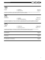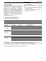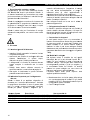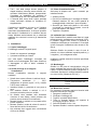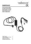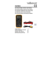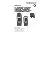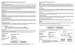
1
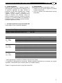
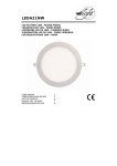
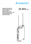
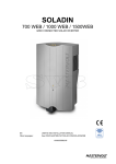
G GB N NL I USE ER’S MAN NUAL GEBRUIKE ERSHAN NDLEIDIN NG INSTRUZ ZIONI PE ER L’USO O So oladin n 60 00 Grid connected sollar inverte G er Netgekop N ppelde om mvormer voor v zonn ne-energie e Invertitore solare con colle egamento o alla rete TERVOLT MAST Snijde ersbergweg 9 93, 1105 AN A Amsterdam The Netherlands N Tel.: +31-20-342 + 2 00 21 Fax: +31-20-697 + 1 06 10 www.m mastervolt.co om Copyrigh ht © 2013 Ma astervolt, v 2.9 Decembe er 2013 GB NL I AC plug Netstekker Spina CA SOLADIN 600 Ventilation openings Ventilatieopeningen Fori di ventilazione refer to section 2.2 zie paragraaf 2.2 cfr. la sezione 2.2 LED indicator LED indicatie LED AC mains cord Netsnoer Cavo CA Ventilation opening Ventilatieopening Foro di ventilazione MultiContact plug + MultiContact stekker + Presa MultiContact + Tab to release the mounting lock Lip voor ontgrendeling van de bevestigingsbeugel Linguetta per aprire il blocco di montaggio 2 MultiContact plug – MultiContact stekker – Presa MultiContact – Communication port Communicatie-aansluiting Porta di comunicazione I SOLADIN 600 NL GB GB English Installation Users manual Page 4-5 Page 6-9 Copyright © 2013 Mastervolt. All rights reserved. Reproduction, transfer, distribution or storage of part or all of the contents in this document in any form without the prior written permission of Mastervolt is prohibited. NL Nederlands Installatie Gebruikershandleiding Pagina 4-5 Pagina 10-13 Copyright © 2013 Mastervolt. Alle rechten voorbehouden. Onrechtmatige reproductie, overdracht, distributie of opslag van dit document of een gedeelte ervan in enige vorm zonder voorafgaande geschreven toestemming van Mastervolt is verboden. I Italiano Installazione Instruzioni per l’uso Pagina 4-5 Pagina 14-17 Copyright © 2013 Mastervolt. Tutti i diritti sono riservati. Il contenuto del presente documento, né parte di esso, potrà essere riprodotto, trasferito, distribuito o memorizzato in qualsiasi forma senza il permesso scritto di Mastervolt. Specifications Page 18 Dimensions Page 19 EC declaration of conformity Page 20 3 GB NL I INSTALLATION – INSTALLATIE – INSTALLAZIONE GB 1 2 A NL I Read instructions on page 6 -9 prior to installation Lees vóór installatie eerst de instructies op pagina 10 t/m 13 Prima dell’installazione, leggere le istruzioni a pagina 14-17 Mark the position of the two mounting spots A and B by using the mounting bracket Markeer de plaats van de twee montagegaten A en B met behulp van de montagebeugel. Segnare la posizione dei due punti di riferimento A e B usando il supporto di montaggio If necessary, drill mounting holes at spots A and B Boor, indien nodig, gaten op de posities A en B Se necessario, eseguire dei fori per il montaggio sui punti A e B Fix the mounting bracket to the wall Monteer de montagebeugel op de wand Fissare il supporto alla parete Place the Soladin 600 over the mounting bracket and then move it downwards until it is locked by the mounting bracket Positioneer de Soladin 600 iets boven de montagebeugel en laat hem vervolgens zakken totdat de Soladin vast klikt in de montagebeugel. Collocare l’apparecchio Soladin 600 sopra il supporto, quindi spostarlo verso il basso finché non si blocca sul supporto di montaggio B 3 A B 4 A B 5 4 I INSTALLATION – INSTALLATIE – INSTALLAZIONE GB NL NL GB I 6 Check whether the Soladin 600 is mounted in a secure way. Controleer of de Soladin 600 stevig gemonteerd is. Controllare che Soladin 600 sia montato in maniera sicura. 7 Connect the string cabling to the Soladin 600. If solar irradiation is sufficient, the LED indicator will illuminate red. Sluit de bedrading van de PV-string aan op de Soladin 600. Bij voldoende zoninstraling zal de LED-indicatie rood oplichten Collegare i cavi al Soladin 600. Se l’irradiazione solare è sufficiente, il LED si illumina di rosso. 8 Connect the Soladin 600 to the electric grid. Refer to section 2.2 for directions. Sluit de Soladin 600 aan op het elektriciteitsnet. Zie paragraaf 2.2 voor aanwijzingen Collegare il Soladin 600 alla rete AC. Consultare la sezione 2.2 per istruzioni. refer to section 2.2 zie paragraaf 2.2 cfr. la sezione 2.2 If solar irradiation is sufficient, the LEDindicator starts blinking red: the Soladin 600 is starting up. This may last a few seconds up to 5 minutes Bij voldoende zoninstraling gaat de LED-indicatie rood knipperen: de Soladin 600 start op. Dit kan enkele seconden tot maximaal 5 minuten duren Se l’irradiazione solare è sufficiente, il LED inizia a lampeggiare in rosso: il Soladin 600 si accende. Questo processo potrebbe durare da qualche secondo ad un massimo di 5 minuti After starting up, the LED-indicator starts blinking yellow. Na het opstarten gaat de LEDindicatie geel knipperen. Una volta acceso, il LED inizia a lampeggiare in giallo. If solar irradiation is too low (at night), the indicator will extinguish Bij onvoldoende zoninstraling (bijvoorbeeld ’s nachts) gaat de LED-indicatie uit. Se l’irradiazione solare è troppo bassa (verso sera), la spia scompare – + AC 9 5 GB E ENGLISH 1. Product des scription an nd applicattion gratulations for choosin ng the Masttervolt Soladin Cong 600. The Sola adin 600, further mentioned m as ed solar inverter, used for “Soladin”, is a grrid connecte onversion a and feed ba ack into the e utility grid d of the co the po ower generrated by pho otovoltaic modules. m d with exte ensive saffety The Soladin iss equipped sures to enssure that it switches offf immediattely meas as so oon as the grid voltag ge or freque ency is outt of range e, the AC p plug is disc connected, or the pub blic grid fa ails in opera ation. S is only suitable e for the feedback of so olar The Soladin powe er into the public grid d, not as a stand-alo one invertter. 2. Safety G saffety instruc ctions 2.1 General stall and u use the So oladin acco ording to the t Ins insstructions sttated in thiss manual. Th he Soladin must be disconneccted from the t ele ectric grid during installation work.. Co onnections and safe ety measurres must be ex xecuted acccording to o the locally applicable reg gulations Th he Soladin m must be use ed in accord dance with the t specificationss as stated on o page 18. ever open th he housing as high voltages may be Ne pre esent inside e! mportant d directions for f AC grid d connectio on 2.2 Im The Soladin is equipped with a so o called “antiding safetyy device”. It ensure es immedia ate island switch h off in case of grid faiilure. Europ pean countrries mainttain different regulatio ons with re egard to antiisland ding devices and the supply s of energy backk to the utility grid in n general. Always A acq quaint yours self with the t latest lo ocal regulattions on this topic befo ore installation. Checck from the e part number on the tyype Partt number 1300 000600 1300 000601 1300 000660 1300 000670 Table e1 6 Descrip ption Soladin n 600 230V//50Hz – EU Soladin n 600 230V//50Hz – EU Soladin n 600 230V//50Hz – GB BR Soladin n 600 230V//50Hz – ITA A USE ERS MAN NUAL SO OLADIN 600 umber plate e whether th he version of the Sola adin is nu ap ppropriate to o be conne ected to the e local utilityy grid. Re efer to table e 1. ever connec ct the Soladin to a utility grid wh hich is Ne no ot suitable fo or the use of o the apparratus! AC grid co onnection in the Neth herlands In the Netherrlands, a ma aximum of one Soladin n may e connected d to each exxisting electtric branch circuit be wh hich is prote ected by a 16 Amp brreaker. To do d so, inssert the AC C plug into a wall sockket that is part p of su uch electricitty branch ciircuit. AC grid co onnection in other co ountries In most coun ntries use of o pluggable e grid invertters is ohibited. pro Th herefore th he Soladin must be e installed in a to a pe ermanent installation, directly connected c de edicated ele ectricity bran nch circuit to t which no o other ele ectrical equ uipment is connected. c T do so, th To he AC plu ug must be removed from f the ma ains cord prior to insstallation. Then T conne ect the ma ains cord to t the ele ectricity bra anch circuit by means of a junctio on box (no ot included in the delivvery). 3 PV modu ules and sttrings 2.3 A solar systtem consis sts of seve eral photovvoltaic olar) mod dules, further mentioned as “PV (so mo odules”. The PV-modu ules are con nnected in series to form a so called c “strin ng”. These strings consist of gative (–) connection c a positive (+)) and a neg which an be connected dire ectly to th he Soladin. The ca vo oltages pressent on the ese strings are not sa afe to tou uch and can nnot be switched off Th herefore th he solar system s sh hould mee et the folllowing speccifications: Maximum open circu uit string voltage v at lowest e of the PV V moduless: 150 possible temperature f the VDC. See table 3 for typical conffigurations for Soladin. olated PV-w wiring Double iso Allow wed to be used u in: The Netherlands N s The Netherlands N s Engla and, Ireland d Italy USERS MANUAL SOLADIN 600 All cables of the string should have double isolation and must be fitted with pre-assembled MultiContact connectors (Ø4mm). Consult an installer for the availability of such cable assemblies. Do not assemble these yourself! Depending on local applicable regulations the use of additional DC switch may be mandatory Contact an installer if the solar-system does not comply with the above mentioned stipulations. Due to possible high voltages installation and modification may only be carried out by a qualified electrician who is familiar applicable regulations and standards. 3. Installation 3.1 Unpacking The delivery consists of the following parts: The Soladin with mounting bracket This user’s manual After unpacking, check the Soladin for possible damage. Do not use the Soladin if it is damaged. If in doubt, contact your supplier. 3.2 Choosing the location to install Obey the following stipulations during installation: The Soladin is suited for indoor use only. Ambient temperature: 0 ... 50°C; (power derating above 40°C), Humidity: 0-85% non condensing Install the Soladin in the vicinity of a wall socket Do not install the Soladin in environments with heavy dust development or humidity. If the Soladin is installed in the immediate vicinity of living areas, take into account that it produces a slight noise level when operating. Mount the Soladin vertically on a solid, nonresonating, wall. Mount the Soladin in such a way that obstruction of the airflow through the ventilation openings is prevented No objects must be located within a distance of 20 cm around the Soladin. Multiple Soladins must be mounted next to each other, not above each other. Minimum spacing: 20 cm. ENGLISH GB 3.3 Things you need to install the Soladin Make sure you have all the parts you need to install the Soladin: The Soladin (included) Two screws (with plugs) to mount the Soladin. Maximum diameter: 4.5 mm. Use mounting materials which are suitable to carry the weight of the Soladin. Tools to fix the screws / bolts with plugs into the wall (screwdriver, drilling machine, a set of drills, a pencil) Wire cutter, wire strip tool. 3.4 Directions for installation During installation you can check by means of the LED-indicator whether the installation is done properly. This check can only be carried out when sufficient irradiation is present. Installation should therefore be carried out during daytime only. Although the Soladin is protected against wrong polarity, the positive (+) and negative (–) of the solar connections should not be exchanged. Install the product according to the instructions stated on page 4 and 5. 3.5 Remote monitoring The Soladin has a communication port that can be connected to the COM-port (RS232) of a PC or laptop. Use the optional “Mastervolt PC–link” interface and cable to set up a connection. Part number 130391030 Description PC-link Soladin 600, incl. communication cable, 2m 3.6 Decommissioning To put the Soladin out of operation, follow the instructions in order of succession as described below 1. Switch off the AC grid 2. Disconnect the AC wiring 3. Disconnect the MultiContact plugs. 4. Push on the lower tab of the mounting bracket to release the mounting lock. 5. Lift the Soladin upwards for approximately 1 cm. 6. Move the Soladin straight from the wall 7 GB ENGLISH USERS MANUAL SOLADIN 600 4. Operation After installation the Soladin will switch on automatically if solar irradiation is sufficient. The Soladin operates automatically: there is no need for adjustment or operation. The Soladin has no ON/OFF switch; switch off the AC grid to switch it off. Do not disconnect the MultiContact plugs during operation of the Soladin! No specific maintenance is required. If necessary, use a soft clean cloth to clean the Soladin. Never use any liquids, acids and/or scourers. 4.1 LED indicator The operation mode of the Soladin is displayed by means of a LED indicator at the front side of the housing. In normal operation it flashes yellow: the longer the LED illuminates yellow, the more power is converted. Indication of the LED Meaning Insufficient irradiation LED is off No power from the PV modules LED is off Yellow blinking ▬ ▬ ▬ Slow blinking long red pulses ▬▬▬▬▬▬ Fast blinking long red pulses ▬▬▬▬▬▬▬▬ Uninterrupted red Red blinking 1 time Red blinking 2 times Red blinking 3 times Red blinking 4 times Red blinking 5 times Red blinking 6 times Red blinking 7 times Table 2 8 Normal operation Reclosure time Restart time lag If the irradiation of the PV-modules is insufficient, for instance at night, the Soladin switches off automatically. When switched off, the LED indicator is off. 4.2 Failures As long as the indication LED isn’t illuminated red, no failure is detected: the Soladin is operating normally. If an error occurs, it is detected by the apparatus itself: the LED indicator turns red. See table 2. Consult an installer, if you cannot solve the problem by means of the table below. NOTE: during sunrise or sunset a low Solar voltage is detected by Soladin, indicated by a red blinking LED indicator. This is a normal situation What to do? Nothing. The Soladin operates normally, but irradiation of the PV modules is insufficient (for instance during night time) Consult an installer if the LED indicator is off during daytime. The wiring between the PV modules and the Soladin might be defective. Check for loose connections or incorrect polarity. Nothing. The Soladin operates normally. The longer the LED illuminates yellow, the more power is converted. Nothing. After the Soladin was (re)connected to the AC grid, it checks the quality of the AC grid before it starts operating normally. This may take up to 5 minutes. Nothing. A system check is carried out during sunrise. This may take up to 15 seconds before the Soladin starts operating normally. No grid voltage Check the AC grid; check the fuse in the meter cupboard. Solar voltage too low Nothing; normal condition during sunrise and sunset. Consult an installer if the problem remains while irradiation of the PV modules is sufficient. Error in the PV installation. Are the specifications of the PV modules in accordance with the Soladin? Consult an installer. Error in the PV installation. Are the specifications of the PV modules in according with the Soladin? Check the grid connection. Solar voltage too high AC grid voltage too high AC grid voltage too low Grid frequency too high or too low Internal temperature too high NTC error Check the grid connection. Check the grid connection. Air flow of the Soladin may not be obstructed. If the problem remains, switch off the Soladin (see chapter 4) and consult an installer. Consult an installer for repair of a defective safety device in the Soladin. USERS MANUAL SOLADIN 600 ENGLISH GB 6. Liability Mastervolt cannot be held liable for: Possible errors in this included manual and the consequences of these. Use that is inconsistent with the purpose of the product. 5. Guarantee terms Mastervolt guarantees that this product was built according to the legally applicable standards and stipulations. During production and before delivery all products are exhaustively tested and controlled. If you fail to act in accordance with the regulations, instructions and stipulations in this user’s manual, damage can occur and/or the product will not fulfill the specifications. This may mean that the guarantee will become null and void. The guarantee period is 5 years. 7. Summarized specifications Soladin 600 Refer to page 18 for extended specifications Maximum PV power: MPP voltage: Maximum input voltage U-oc @ -10°C: Maximum MPP current: 700 Wp 45-125 V DC 150 V DC 8 A DC PV module 36 cells Uoc = 28V* Umpp = 18V* Power 75 Wp 100 Wp 125 Wp 150 Wp One string 4 - 6 in series 4 - 6 in series 4 - 5 in series 4 (5) in series Two strings in parallel** 4 in series ---- 54 cells Uoc = 32V* Umpp = 27V* 75 Wp 100 Wp 125 Wp 150 Wp 175 Wp 3 - 4 in series 3 - 4 in series 3 - 4 in series 3 - 4 in series 3 - 4 in series 3 - 4 in series 3 in series ---- 72 cells Uoc = 43V* Umpp = 36V* 75 Wp 100 Wp 125 Wp 150 Wp 175 Wp 2 - 3 in series 2 - 3 in series 2 - 3 in series 2 - 3 in series 2 - 3 in series 2 - 3 in series 2 - 3 in series 2 in series 2 in series 2 in series * Approximate value; refer to the specifications of the manufacturer ** Configuration for one string is stated. Use MultiContact branch connectors to connect two strings in parallel. MultiContact part numbers: PV-AZS4 (positive) and PV-AZB4 (negative) Table 3: Typical string configurations for the Soladin 600 9 NL N NEDERLA ANDS GEBRU UIKERSH HANDLEIIDING SO OLADIN 600 1. Productbesc chrijving en e toepassiing et uw keu uze voor de d Mastervvolt Gefelliciteerd me Solad din 600. De e Soladin 60 00, verder aangeduid a als “Soladin”, is ee en netgeko oppelde zo onneomvorm mer mee elektrissche zonne e-energie, opgewekt o do oor waarm PV (p photovoltaïssche) panellen, rechtstreeks aan het openb bare elektriciteitsnet ge eleverd kan n worden. oladin is uittgerust met diverse bevveiligingen die De So ervoo or zorgen dat het apparaat onmiddellijk uitsch hakelt zodra a de netspa anning of ne etfrequentie e te hoog of te laag is, de stekkker uit het stopcontactt is men of de netspanning n g uitvalt. genom S is uitsluitend geschikt voo or het leverren De Soladin van in n zonnepan nelen opgew wekte elektrrische enerrgie aan het h elektriciteitsnet. Ze elfstandig gebruik zond der het ellektriciteitsn net is niet mogelijk. m 2. Veiligheid A v veiligheids sinstructies s 2.1 Algemene Ins stalleer en gebruik de Soladin me et inachtname van de instruccties in deze e gebruikerrshandleidin ng. Tijdens installatie van de e Soladin moet deze altijd et elektricite eitsnet. lossgekoppeld zijn van he Aa ansluitingen n en bev veiligingen moeten in ov vereenstemm ming met de plaatse elijk gelden nde vo oorschriften worden uitg gevoerd. Ge ebruik de S Soladin in overeenstem o mming met de specificaties zzoals aange egeven op pagina p 18. In verband m met de aanw wezige hog ge spanning gen ag u de beh huizing nooiit openen! ma B e aanwijzingen voor in nstallatie 2.2 Belangrijke De Soladin S is u uitgerust me et een bevveiliging teg gen eiland dbedrijf. D Deze bev veiliging schakelt de uitgan ngsspannin ng van de omvormer o o onmiddellijk k af zodra a de netsp panning we egvalt. Euro opese land den hante eren verscchillende eisen e ten aanzien van v eiland dbeveiliging g en te eruglevering g aan het elektrriciteitsnet in het algem meen. Raad dpleeg stee eds de meest m recen nte plaatsellijk geldend de bepaling gen over dit onderw werp voord dat u met de installa atie nt. begin er Artikelnumme 000600 1300 1300 000601 1300 000660 1300 000660 Tabel 1 10 ontroleer aa an de hand d van het artikelnumm a mer op Co de e typenumm merplaat of o de verssie van Soladin ge eschikt is voor insta allatie op het plaatsselijke ele ektriciteitsne et. Zie tabel 1. Slu uit de Sola adin nooit aan a op een n elektricite eitsnet wa aarvoor het apparaat niet n toegesta aan is! Aansluitin ng op het Nederlands N se elektricite eitsnet In Nederland mag per be estaande e elektriciteitsg groep, gezekerd met m een 16 Ampère A zekering, max ximaal afg éé én Soladin worden aangesloten. Hiertoe ste eekt u de e stekker in het stopcontact dat in n verbinding g staat me et de desbe etreffende groep. g Aansluitin ng op het elektriciteits e snet in and dere landen In de meeste e andere landen is hett niet toege estaan en omvorme er te gebruiken waarb bij de energ gie via ee ee en stekkerve erbinding aa an het elekktriciteitsnet wordt terrug geleverd. In zulke geva allen mag u de Soladin alleen gebruiken de installattie, rechtsttreeks in een vastt opgesteld angesloten op een n aparte, afschake elbare aa ele ektriciteitsgrroep, waarop geen andere appa araten zijn aangeslotten. allatie de ne etstekker va an het Hiertoe moet u vóór insta ansluitsnoerr van de Soladin S verw wijderen. Daarna D aa mo oet u hett netsnoer op de elektriciteits e sgroep aa ansluiten via v een apart aan nsluitkastje (niet me eegeleved met m de Sola adin). 3 PV panelen en strin ngs 2.3 Ee en zonne-e energiesyste eem besta aat uit mee erdere fottovoltaïsche e zonne e-energiepanelen, v verder aa angeduid als a “PV pa anelen”. Me eerdere in serie ge eschakelde PV panele en vormen samen een z.g. strring. Deze strings hebben een positieve (+) ( en ee en negatiev ve (–) aanssluiting, die rechtstree eks op de e Soladin aa angesloten kunnen worrden. De e spanning op de bek kabeling van n deze strin ngs is nie et aanraakvveilig en kan n niet afgesschakeld wo orden. Da aarom dien nt het zonn ne-energiessysteem aa an de vo olgende spe ecificaties te e voldoen: Maximale open kle emspanning g bij de laagst ur van de PV-panelen P n: 150 mogelijke temperatuu t 3 voor mogelijke samenstellingen VDC. Zie tabel van PV panelen voor de Soladin. P bedradin ng Dubbel geïïsoleerde PV Om mschrijving g Solladin 600 23 30V/50Hz QNS Q – EU Solladin 600 23 30V/50Hz QNS Q – EU Solladin 600 23 30V/50Hz QNS Q – GBR R Solladin 600 23 30V/50Hz QNS Q – ITA Toeg gestaan vo oor gebruik k in: Nede erland Nede erland Enge eland, Ierlan nd Italië ë GEBRUIKERSHANDLEIDING SOLADIN 600 Alle bedrading van de string dient te bestaan uit kant-en-klare dubbelgeïsoleerde kabels die reeds voorzien zijn van MultiContact connectors (Ø4mm). Raadpleeg een installateur voor de levering van dergelijke kabels. Assembleer deze kabels niet zelf! Afhankelijk van de plaatselijk geldende voorschriften kan het gebruik van een separate DC schakelaar verplicht zijn. Raadpleeg een installateur indien het zonneenergiesysteem niet aan de hierboven aangegeven voorwaarden voldoet. In verband met de aanwezigheid van hoge spanningen mogen installatiewerkzaamheden uitsluitend worden uitgevoerd door een daartoe gekwalificeerde elektricien, die bekend is met de van toepassing zijnde voorschriften en standaarden. 3. Installatie 3.1 Uitpakken De levering omvat de volgende onderdelen: De Soladin met montagebeugel Deze gebruikershandleiding Controleer na het uitpakken de Soladin op mogelijke beschadigingen. In geval van beschadigingen moet u de Soladin niet gebruiken Raadpleeg bij twijfel altijd uw leverancier. 3.2 Bepaal de plaats om de Soladin te installeren Let hierbij op de volgende punten: De Soladin is uitsluitend geschikt voor gebruik binnenshuis. Omgevingstemperatuur: 0 ... 50°C; (bij temperaturen hoger dan 40°C wordt het vermogen gereduceerd). Luchtvochtigheid: 085% niet condenserend. Installeer de Soladin in de nabijheid van een stopcontact. Installeer de Soladin niet in een zeer stoffige of vochtige omgeving. Bij installatie in de woning moet rekening worden gehouden met een geringe geluidsproductie tijdens de werking van het apparaat. De Soladin dient verticaal te worden gemonteerd op een stevige, niet-resonerende wand. Het apparaat dient zodanig gemonteerd te worden dat de luchtstroom door de ventilatieopeningen niet belemmerd wordt Houd rondom de Soladin tenminste 20 cm. ruimte vrij Bij installatie van meerdere Soladins moeten deze naast elkaar gemonteerd worden, niet NEDERLANDS NL boven elkaar. Minimale onderlinge afstand: 20 cm. 3.3 Benodigdheden voor installatie van de Soladin Dit heeft u nodig voor de installatie van de Soladin: De Soladin (meegeleverd) Twee schroeven (met pluggen) om de Soladin te monteren. Maximale diameter: 4,5 mm. Gebruik montagematerialen die geschikt zijn voor het gewicht van de Soladin. Gereedschappen om de schroeven en pluggen in de wand te bevestigen (schroevendraaier, boormachine, boortjes, een potlood) 3.4 Installatieaanwijzingen U kunt aan de hand van de LED-indicatie controleren of u de installatie juist heeft uitgevoerd. Deze controle kan alleen worden uitgevoerd indien er enige zonne-instraling is. Voer de installatie daarom ook uitsluitend overdag uit. Hoewel de Soladin tegen ompoling beveiligd is, mogen de positieve (+) en negatieve (–) aansluiting van de string niet verwisseld worden. Installeer de Soladin zoals aangegeven in de instructies op pagina 4 en 5. 3.5 Monitoring De Soladin beschikt over een communicatie-uitgang die u kunt aansluiten op de COM-port (RS232) van een PC of laptop. Maak gebruik van de optionele “Mastervolt PC–link” interface en kabel om deze verbinding tot stand te brengen. Artikelnummer Omschrijving 130391030 PC-link Soladin 600, incl. communicatiiekabel, 2m Buiten bedrijf stellen De Soladin kan alleen veilig buiten bedrijf worden gesteld indien er geen vermogen wordt omgezet. Volg daarom onderstaande stappen in de aangegeven volgorde indien u de Soladin buiten wilt stellen. 1. Schakel de netspanning af of verwijder de neststekker van de Soladin uit het stopcontact 2. Demonteer AC bedrading 3. Neem de MultiContact stekkers los 4. Druk op de lip voor ontgrendeling van de bevestigingsbeugel. 5. Schuif de Soladin ongeveer 1 cm. omhoog. 6. Verwijder de Soladin van de muur. 11 NL NEDERLANDS GEBRUIKERSHANDLEIDING SOLADIN 600 4. Bediening Na het installeren zal de Soladin bij voldoende zoninstraling inschakelen. De Soladin werkt geheel automatisch; instellingen en bediening zijn daardoor niet nodig. De Soladin heeft geen aan/uit-schakelaar. Om de Soladin uit te schakelen schakelt u de netspanning af of neemt u de netstekker uit het stopcontact. Maak tijdens bedrijf van de Soladin nooit de MultiContact connectoren los! De Soladin is een onderhoudsvrij product. Gebruik eventueel een zachte droge doek om de Soladin schoon te maken. Gebruik nooit vloeibare, bijtende of schurende middelen om de Soladin schoon te maken. 4.1 LED indicatie De werking van de Soladin wordt weergegeven door middel van een LED indicatie aan de voorzijde van het apparaat. In normaal bedrijf knippert deze indicatie geel: hoe langer de indicatie geel brandt, hoe meer vermogen omgezet wordt. LED-indicatie LED is uit LED is uit Geel knipperend ▬ ▬ ▬ Lang rood knipperend Betekenis Onvoldoende instraling (’s nachts) Geen vermogen van de PV panelen Normaal bedrijf Controle van de netspanning Bij onvoldoende lichtinval van de zonnepanelen, bijvoorbeeld ‘s nachts, schakelt de Soladin automatisch uit. De LED-indicatie is dan ook uit. 4.2 Storingen Zolang de LED-indicatie niet rood oplicht is er geen sprake van een storing en werkt de Sunmaster normaal. Eventuele storingen worden door het apparaat zelf gesignaleerd: de LED-indicatie licht rood op. Zie tabel 2 voor de betekenis. Raadpleeg een installateur indien u de storing niet aan de hand van onderstaande tabel kunt verhelpen. OPMERKING: tijdens zonsopkomst en zonsondergang detecteert de Sunmaster een (te) lage spanning. Dit wordt aangeduid door een rood knipperende LED-indicatie. Dit is een normale situatie. Wat te doen? Niets. De Soladin werkt normaal, maar krijgt onvoldoende energie uit de PV panelen (bijvoorbeeld ’s nachts). Raadpleeg een installateur indien de LED overdag uit is. Mogelijk is de bedrading tussen de PV panelen en de Soladin defect. Controleer op losse verbindingen en incorrecte polariteit (+ en – verwisseld). Niets. De Soladin werkt normaal. Hoe langer de indicatie geel brandt, hoe meer vermogen omgezet wordt. Niets. Nadat de Soladin (weer) is aangesloten op het elektriciteitsnet voert deze enkele testen uit. Dit kan maximaal 5 minuten duren. Daarna wordt de Soladin ingeschakeld en gaat normaal werken. Niets. Er wordt een systeemcontrole uitgevoerd tijdens zonsopkomst. Dit duurt maximaal 15 sec. voordat de Soladin zichzelf inschakelt. ▬▬▬▬▬▬ Snel rood knipperend, lang pulsen ▬▬▬▬▬▬▬▬ Constant rood 1x rood knipperend Opstarten 2x rood knipperend Spanning van de PV panelen te hoog 3x rood knipperend 4x rood knipperend 5x rood knipperend 6x rood knipperend Netspanning te hoog Indien de Soladin is uitgerust met een netstekker: steek de netstekker in het stopcontact. Controleer de zekering in de meterkast. Normale situatie tijdens zonsopkomst en zonsondergang. Roep de hulp in van een installateur wanneer dit probleem zich voordoet bij voldoende instraling van de PV-panelen. Fout in het zonne-energiesysteem. Zijn de specificaties van de PV panelen / string in overeenstemming met de Soladin? Raadpleeg een installateur. Fout in het zonne-energiesysteem. Zijn de specificaties van de PV panelen / string in overeenstemming met de Soladin? Controleer de netaansluiting. Netspanning te laag Controleer de netaansluiting. Netfrequentie te hoog of te laag Interne temperatuur te hoog Controleer de netaansluiting. 7x rood knipperend NTC fout Tabel 2 12 Geen netspanning Spanning van de PV panelen te laag Luchtstroom door de Soladin mag niet geblokkeerd worden. Als het probleem blijft aanhouden schakel dan de Soladin uit (zie hoofdstuk 4) en roep de hulp in van een installateur. Roep de hulp van een installateur in voor reparatie van een defect onderdeel in het veiligheidscircuit van de Soladin. GEBRUIKERSHANDLEIDING SOLADIN 600 NEDERLANDS NL 6. Aansprakelijkheid Mastervolt kan niet aansprakelijk worden gesteld voor: Eventuele fouten in bijbehorende handleiding en de gevolgen daarvan, Ander gebruik geldend als niet conform de bestemming van het product. 5. Garantiebepalingen Mastervolt garandeert dat dit product is geproduceerd volgens de wettelijk van toepassing zijnde normen en bepalingen. Gedurende de productie en voor aflevering zijn alle producten uitvoerig getest en gecontroleerd. Wanneer niet volgens de in deze handleiding gegeven voorschriften, aanwijzingen en bepalingen wordt gehandeld, kunnen beschadigingen ontstaan en/of het apparaat zal niet aan de specificaties voldoen. Een en ander kan inhouden dat de garantie komt te vervallen De garantietermijn is vijf jaar. 7. Verkorte specificaties Soladin 600 Zie pagina 18 voor uitgebreide specificaties. Maximaal PV vermogen: MPP spanningsbereik: Maximale ingangsspanning U-oc bij -10°C: Maximale MPP stroom: 700 Wp 45-125 V DC 150 V DC 8 A DC PV paneel 36 cells Uoc = 28V* Umpp = 18V* Vermogen 75 Wp 100 Wp 125 Wp 150 Wp 1 string 4 - 6 in serie 4 - 6 in serie 4 - 5 in serie 4 (5) in serie 2 strings parallel** 4 in serie ---- 54 cells Uoc = 32V* Umpp = 27V* 75 Wp 100 Wp 125 Wp 150 Wp 175 Wp 3 - 4 in serie 3 - 4 in serie 3 - 4 in serie 3 - 4 in serie 3 - 4 in serie 3 - 4 in serie 3 in serie ---- 72 cells Uoc = 43V* Umpp = 36V* 75 Wp 100 Wp 125 Wp 150 Wp 175 Wp 2 - 3 in serie 2 - 3 in serie 2 - 3 in serie 2 - 3 in serie 2 - 3 in serie 2 - 3 in serie 2 - 3 in serie 2 in serie 2 in serie 2 in serie * Benadering van de werkelijke spanning; raadpleeg de specificaties van de producent ** Configuratie van 1 string is weergegeven. Met behulp van MultiContact koppelstukken kunt u twee strings parallel schakelen. MultiContact bestelnummers: PV-AZS4 (positief) en PV-AZB4 (negatief) Tabel 3: Typische configuraties van PV-strings voor de Soladin 600 13 I IT TALIANO O 1. Descrizione e del prodotto e utilizzzo Cong gratulazioni per aver scelto s Mastervolt Soladin 600. Soladin S 600 0, da qui in poi chiamato “Soladin””, è un invverter fotovvoltaico per connessione rete, usa ato per la a conversion ne e la diffu usione in rette dell’enerrgia generrata da mod duli fotovoltaici. din è equipa aggiato con n misure di sicurezza che c Solad ne ga arantiscono o lo spegnimento imm mediate se la frequenza o il vvoltaggio so ono fuori ra ange, la spina AC è disconnesssa o la rete risulta asse ente. din è adatto solo per l’immissione di enerrgia Solad solare e nella rete e pubblica, non come inverter sta and alone e. 2. Sicurezza struzioni g generali di sicurezza s 2.1 Is Ins stallare Soladin segue endo le istrruzioni inclu use ne el presente m manuale. As ssicurarsi ch he Soladin sia scolleg gato dalla re ete du urante l’in nstallazione. A questo scopo, dissinserire la spina CA dalla presa a muro. I collegament c ti e le funzioni di sicu urezza devo ono es ssere eseguite in co onformità con c le norme loccali. So oladin devve essere utilizzato secondo le specifiche teccniche, com me indicato a pagina 18 8. No on aprire ill rivestimen nto in quanto all’interrno po otrebbe esse ervi alta ten nsione! ndicazioni importantii per il colle egamento 2.2 In alla a rete di Solad din è dotato di un cosidetto c “ “dispositivo sicure ezza per il controllo dell'isolame d ura nto”. Assicu lo spegnimento immediato in caso di guasto de ella ni europee e impongon no condizioni rete. Le nazion uanto rigua arda i disp positivi perr il diversse per qu mero di parrte Num 1300 000600 1300 000601 1300 000660 1300 000670 Tabella 1 14 INST TRUZION NI PER L’USO L SO OLADIN 600 ontrollo dell'isolamento o e l’erogazzione di en nergia co alla rete. Prima P dell'iinstallazione e, si preg ga di c gli ultimi ag ggiornamen nti e infformarsi circa reg golamenti lo ocali relativi a tale argo omento. Co ontrollare su ul numero di d articolo nell’etichetta n a se la ve ersione di Soladin S può ò essere co ollegata alla a rete loccale. Consu ultare la tabella 1. No on collegare Soladin se la rete non è ada atta al pre esente apparecchio! Collegame ento alla re ete AC in O Olanda In Olanda è possibile collegare c un n solo Sola adin al o esistente e a 16 Amp p. Per cirrcuito elettrrico derivato farre questo in nserire la prese AC ne ella spina a muro ch he fa parte di d quel circu uito elettrico o. Connessio one in altrii paesi In molti paes si europei l’uso e la connessio one di c ettrica invverter con connession e diretta alla presa ele di casa sono proibiti. In questi cassi il Soladin n deve esssere installlato in un circuito elettrico isollato e de edicato. In Italia si pu uò invece collegare c Soladin dirrettamente alla presa elettrica e domestica purchè il ge eneratore fo otovoltaico non n sia mag ggiore o ugu uale a 1 kWp. k 3 Moduli PV P e stringh he 2.3 Un n impianto solare è costituito da vari moduli m fottovoltaici, da d qui in poi p chiamatti “moduli PV”. P I mo oduli PV sono collegati in serie e a formare e una co osidetta “strringa”. Tali stringhe so ono costituite da un n collegame ento positivo o (+) e da uno negativo (–) in connessio one diretta con Soladin. Le te ensioni esenti su queste striinghe non sono sicure da pre tocccare e non n possono venire v disatttivate. L’impianto solare s devve quindi disporre delle eguenti speccifiche tecniiche: se Massima tensione t a circuito ape erto della stringa s con una temperatura t a dei modu uli PV più bassa possibile: 150 1 VCC. Consultare C l tabella 3 per le la configurazzioni tipiche di Soladin. d isola ato Cavo PV doppio Descrizione D e Soladin 600 230V/50Hz z QNS – EU U Soladin 600 230V/50Hz z QNS – EU U Soladin 600 230V/50Hz z QNS – GB BR Soladin 600 230V/50Hz z QNS – ITA A Uso o consentitto in: Pae esi Bassi Pae esi Bassi Ingh hilterra, Irlanda Italia INSTRUZIONI PER L’USO SOLADIN 600 Tutti i cavi della stringa devono disporre di doppia isolazione e devono essere utilizzati con i connettori MultiContact (Ø4mm) preassemblati. Consultare un installatore per verificare la disponibilità di tali cavi. Non assemblarli da soli! A seconda delle norme locali vigenti, potrebbe essere necessario utilizzare un contattore CC supplementare. Contattare un installatore nel caso in cui l’impianto solare non fosse conforme alle condizioni menzionate precedentemente. A causa di possibile alta tensione, l’installazione e le modifiche devono essere effettuate esclusivamente da un elettricista qualificato che conosca le norme e gli standard da applicare. 3. Installazione 3.1 Aprire l’imballaggio L’imballaggio contiene i seguenti pezzi: I 3.3 Prima di installare Soladin Assicurarsi di disporre tutti i pezzi necessari per installare Soladin: Soladin (incluso) Due viti (con tassello) per il montaggio di Soladin. Diametro massimo: 4,5 mm. Usare materiali di montaggio adatti a sostenere il peso di Soladin. Strumenti per fissare alla parete le viti/i bulloni con tasselli (un cacciavite, un trapano, un set di punte per trapano, una matita) Tagliacavi, crimpatrice. 3.4 Indicazioni per l’installazione Dopo l’installazione è possibile controllare se è stata portata a termine correttamente controllando il LED. È possibile eseguire tale verifica in presenza di irradiazione sufficiente per l’accensione. Si consiglia quindi di eseguire l’installazione solo durante le ore diurne. Sebbene Soladin sia protetto in caso di errori di polarità, non si deve cambiare la polarità positiva (+) e negativa (–) dei collegamenti solari. Soladin con supporto di montaggio Il presente manuale per l’utente Una volta aperto l’imballaggio, controllare che Soladin non sia danneggiato. Non usare Soladin se è danneggiato. In caso di dubbi, contattare il rivenditore. 3.2 Scelta del luogo in cui eseguire l’installazione Durante l’installazione osservare le condizioni: ITALIANO seguenti Soladin deve essere utilizzato in ambienti interni. Temperatura ambientale: 0 ... 50°C; (dissipazione di potenza sopra i 40°C), umidità: 0-85% senza condensa. Installare Soladin in prossimità di una presa a muro. Non installare Soladin in ambienti in cui si concentra eccessiva polvere o umidità. Se Soladin viene installato nelle immediate vicinanze di zone abitate, tenere presente che produce rumore durante il funzionamento. Montare Soladin in verticale su una parete solida, priva di risonanza. Montare Soladin in modo da evitare di ostruire il flusso dell’aria dai fori di ventilazione. Non collocare alcun oggetto entro una distanza di 20 cm da Soladin. Installare il prodotto secondo le istruzioni specificate a pagina 4 e 5. 3.5 Monitoraggio Soladin ha una porta di comunicazione che può essere collegata alla com-port (RS 232) di un PC o Laptop. Per poter effettuare questo collegamento, è necessario acquistare la relativa interfaccia optional con cavo incluso (“Mastervolt PC Link”): Articolo nr. 130391030 Descrizione PC-link Soladin 600, Cavo di comunicazione 2mt incluso 3.6 Messa fuori servizio Per smontare il Sunmaster seguire le istruzioni nella sequenza descritta qui di seguito: 1. Spegnere la tensione AC 2. Scollegare il cablaggio AC 3. Togliere i connettori MultiContact 4. Tirare la linguetta inferiore del supporto di montaggio per aprire il blocco. 5. Sollevare Soladin di circa 1 cm. 6. Spostare Soladin in verticale rispetto alla parete. 15 I ITALIANO INSTRUZIONI PER L’USO SOLADIN 600 4. Funzionamento Dopo aver eseguito l’installazione, Soladin si accende automaticamente se l’irradiazione solare è sufficiente. Soladin funziona automaticamente: non è necessario effettuare alcuna regolazione. Soladin non dispone di interruttore ON/OFF. Per spegnerlo, spegnere la tensione AC o disinserire la spina CA dalla presa CA. Non disinserire le spine MultiContact durante il funzionamento di Soladin! Non è necessaria alcuna manutenzione specifica. Se necessario, usare un panno morbido per pulire Soladin. Non utilizzare liquidi, acidi e/o spugnette. 4.1 LED Il modo di funzionamento di Soladin viene visualizzato grazie ad un LED situato nella parte anteriore del rivestimento. In funzionamento normale lampeggia in giallo: quanto più velocemente lampeggia il LED, tanta più potenza viene convertita. Indicazione del LED LED spento LED spento Lampeggiamento giallo ▬ ▬ ▬ Impulsi rossi lunghi e lampeggiamento lento ▬▬▬▬▬▬ Impulsi rossi lunghi e lampeggiamento veloce ▬▬▬▬▬▬▬▬ Rosso continuo 1 lampeggiamento in rosso 2 lampeggiamenti in rosso 3 lampeggiamenti in rosso 4 lampeggiamenti in rosso 5 lampeggiamenti in rosso 6 lampeggiamenti in rosso 7 lampeggiamenti in rosso Tabella 2 16 Significato Irradiazione non sufficiente Nei moduli PV non passa la corrente Funzionamento normale Orario di spegnimento Ritardo di riavvio Nessuna tensione di rete Tensione solare troppo bassa Tensione solare troppo alta Tensione rete CA troppo alta Tensione rete CA troppo bassa Frequenza di rete troppo alta o troppo bassa Temperatura interna troppo alta Errore NTC Se l’irradiazione dei moduli PV non è sufficiente, per esempio di notte, Soladin si spegne automaticamente. Quando si spegne, scompare anche il LED. 4.2 Guasti Finché il LED non si illumina di rosso, non viene rilevato alcun guasto: Soladin funziona normalmente. In caso di errore, questo viene rilevato direttamente dall’apparecchio: il LED diventa rosso. Consultare la tabella 2. Se non si riesce a risolvere l’inconveniente seguendo la tabella di seguito, consultare un installatore. NOTA: all’alba o al tramonto viene rilevata una bassa tensione solare da Soladin, indicata con un LED rosso lampeggiante. È una situazione normale. Cosa fare? Niente. Soladin funziona normalmente, ma l’irradiazione dei moduli PV non è sufficiente (per esempio durante le ore notturne). Se il LED si trova spento nelle ore diurne, consultare un installatore. I cavi tra i moduli PV e Soladin potrebbero essere difettosi. Controllare che non vi siano collegamenti sbagliati o polarità non corrette. Niente. Soladin funziona normalmente. Quanto più veloce lampeggia la spia, più potenza viene convertita. Niente. Dopo aver ricollegato Soladin alla rete CA, verifica la qualità della rete CA prima di funzionare normalmente. Occorrono oltre 5 minuti. Niente. All’alba viene eseguita una verifica dell’impianto. Occorrono un massimo di 15 secondi prima che Soladin inizi a funzionare normalmente. Controllare il collegamento della rete o inserire la presa CA di Soladin alla rete a muro; controllare il fusibile nel contatore. Condizioni normali all’alba ed al tramonto. Se l’inconveniente persiste nonostante l’irradiazione dei moduli PV sia sufficiente, consultare un installatore. Errore nell’installazione PV. Le specifiche tecniche dei moduli solari sono conformi con Soladin? Consultare un installatore. Errore nell’installazione PV. Le specifiche tecniche dei moduli solari sono conformi con Soladin? Controllare il collegamento della rete. Controllare il collegamento alla rete. Controllare il collegamento alla rete. Controllare che il flusso d’aria a Soladin sia libero e non ostruito. Se il problema persiste, spegnere Soladin e consultare un installatore. Consultare un installatore per riparare il dispositivo di sicurezza difettoso di Soladin. INSTRUZIONI PER L’USO SOLADIN 600 ITALIANO I 6. Responsabilità Mastervolt non si ritiene responsabile in caso di: possibili errori nel manuale allegato ed eventuali conseguenze derivanti. l’uso non conforme alle caratteristiche tecniche del prodotto. 5. Termini di garanzia Mastervolt garantisce che il seguente prodotto è stato fabbricato in conformità con gli standard e con le specifiche applicabili per legge. Durante la produzione e prima della consegna tutti i prodotti vengono sottoposti a prove accurate e poi controllati. Se non si agisce in conformità con le norme, le istruzioni e le condizioni incluse nel presente manuale dell’utente, potrebbero verificarsi dei danni e/o il prodotto potrebbe non soddisfare le specifiche tecniche. In tal caso, la garanzia decade. Il periodo di garanzia è di 5 anni. 7. Principali specifiche tecniche del Soladin 600 Vedere pagina 18 per le specifiche dettagliate Potenza massima FV Campo di voltaggio MPP: Voltaggio massimo di ingresso U-oc @ -10°C: Massima corrente MPP 700 Wp 45-125 V DC 150 V DC 8 A DC Modulo PV 36 celle Uoc = 28V* Umpp = 18V* Potenza 75 Wp 100 Wp 125 Wp 150 Wp Una stringa 4 - 6 in serie 4 - 6 in serie 4 - 5 in serie 4 (5) in serie Due stringhe in parallelo** 4 in serie ---- 54 celle Uoc = 32V* Umpp = 27V* 75 Wp 100 Wp 125 Wp 150 Wp 175 Wp 3 - 4 in serie 3 - 4 in serie 3 - 4 in serie 3 - 4 in serie 3 - 4 in serie 3 - 4 in serie 3 in serie ---- 72 celle Uoc = 43V* Umpp = 36V* 75 Wp 100 Wp 125 Wp 150 Wp 175 Wp 2 - 3 in serie 2 - 3 in serie 2 - 3 in serie 2 - 3 in serie 2 - 3 in serie 2 - 3 in serie 2 - 3 in serie 2 in serie 2 in serie 2 in serie * Valore approssimato; consultare le specifiche tecniche del produttore ** Si specifica la configurazione di una stringa. Utilizzare connettori MultiContact per connettere due stringhe in parallelo. Codici MultiContact: PV-AZS4 (positivo); PV-AZB4 (negativo). Tabella 3: Configurazione tipica di stringa per Soladin 600 17 SPECIFICATIONS Model Part number: Manufacturer: Operating temperature: Storage temperature: Relative humidity: Protection degree: Safety class: Dimensions (H x W x D): Weight: Casing: Input (DC) Nominal power @25 °C: PV power range: MPP voltage range: Maximum voltage: MPP current: MPP tracker: Start-up power: String connection: Grid output (AC) Voltage: Nominal power: Maximum current: Fuse: Frequency: Cos phi: Stand-by power: Maximum efficiency: EU efficiency: AC connection: Safety devices Island protection: Power limiting: Temperature protection: Reversed DC polarity: Monitoring Indicator: Correct operation: Grid or inverter fault: Compliance CE compliance: EMC directive: Emission: Harmonics: Immunity: LV directive: Electric safety: Soladin 600 EU Soladin 600 GBR Soladin 600 ITA 130000600, 130000601 130000660 130000670 Mastervolt, Amsterdam, the Netherlands 0°C to 40°C (full power) -20°C to 70°C max. 85%, non condensing IP20 Class II 365 x 143 x 75 mm. Approx. 2 kg. Flame retardant plastic 550W 160-700 Wp 45-125V DC 150V DC 8A dynamic MPP tracker 1W DC @ 45V DC MultiContact connectors 230V (207V-253V) 525W 2,25A in accordance with NL: NTA8493 3,15A -T 50 Hz (49,8-50,2 Hz) 0,99 < 0,05W AC 93% 91% AC mains cord, stranded wires 1.5mm², 1,80 meter (see section 2.2) Voltage and frequency window monitoring; Maximum reaction time: 100 ms. Automatic derating by increasing the operating voltage, depending on the internal inverter temperature. Power derating at higher internal temperature DC connection fully protected LED: yellow / red Yellow, flashing. The longer the LED is lit, the more power is converted Red, 10 different flashing codes Yes 2004/108/EC EN 50081-1 EN 61000-3-2 EN 50082-2 2006/95/EC EN 60950; EN62109-1 Note: Specifications are subject to change without prior notification 18 DIMENSIONS All dimensions are in mm. 19 EC DE ECLARAT TION OF CONFO ORMITY Manufacturrer: Mastervo olt Address: Snijdersb bergweg 93 1105 AN N Amsterdam m The Neth herlands Herewith declares that: Product: Soladin 600 6 ked and complies with the e following sttandards: is CE-mark EMC directtive Environment: 2004/108 8/EC residentia al, commercial and light industrial i Emission Emission - class B: harmonic current c emisssion: EN 55022 EN 61000-3-2 Immunity dard: Generic immunity stand Electrostatic discharge (ESD): E Radiated EMC: Electrical fa ast transientss (EFT) : Surge transsient : Conducted RF disturba ances : Voltage dip ps and short interrupts : Digital radio o telephoness : EN 61000-6-2 EN 61000-4-2 EN 61000-4-3 EN 61000-4-4 EN 61000-4-5 EN 61000-4-6 EN 61000-4-11 204 ENV 502 Safety ge directive : Low Voltag Electrical safety s : 2006/95/EC EN 60950 EN 62109-1 m, Amsterdam B Ing. D.R. Bassie Product Ma anager Solarr 2010 Snijd dersbergw weg 93, 110 05 AN Amssterdam, The T Netherrlands Tel : + 31-20-3422 3 2100 Fax : + 31-20--6971006 Email : in nfo@maste ervolt.com