1
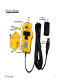
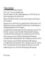
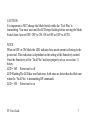
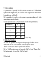
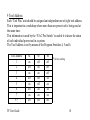
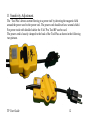
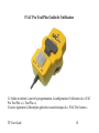
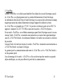
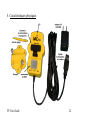
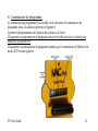
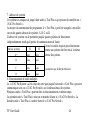
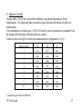
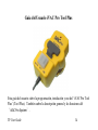
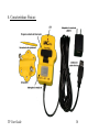
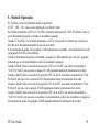
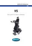
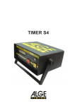
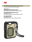
‘iVAC Pro Tool Plus’ User Guide
BCTINT Ltd.
WWW.BCTINT.com
WWW.iVACPRO.com
This User Guide covers the programming, setup and use of the ‘iVAC Pro Tool Plus’ (‘Tool
Plus’).
It also covers the General Description and Features of the ‘IVAC Pro System’.
TP User Guide
1
Table of Contents:
1 Warnings.
2 General Description of ‘iVAC Pro System’
3 ‘iVAC Pro Tool Plus’
4 Physical Features
5 Modes of Operation
6 Program Switch
7 System Address
8 Multi Tool Operation
9 Tool Address
10
11
12
13
14
15
Active Current sense level
Sensitivity Adjustment.
System Test
‘Tool Plus’ Features
Specifications.
Regulatory Compliance
16 Warranty
17 Contact
1. Warnings
Please read the operating instructions before use.
The ‘Tool Plus’ is intended for indoor use, in dry locations only.
The ‘Tool Plus’ is powered from an AC to DC 5V USB adapter
The USB Adapter should only be connected to AC mains circuits at the rated
voltage.
TP User Guide
2
2. General Description of ‘iVAC Pro System’
The ‘iVAC Pro System’ consists of two groups of product.
The first group consists of units that transmit information and a second group of
units that receive the transmitted information. At the present time the first group
that transmit information are the ‘iVAC Pro Remote’ and three versions of the
‘iVAC Pro Tool’ units. The ‘Tool Plus’, the ‘iVAC Pro Tool’, and the ‘iVAC Pro
Tool HP’. The ‘Tool’ units.
The units that receive the information are the ‘iVAC Pro Switch’ which controls
the Dust Collector and the ‘iVAC Pro Blast Gate’.
The ‘Tool’ units monitor the status of its associated power tool. When the power
tool turns on it sends a digital wireless signal instructing the ‘iVAC Pro Switch’ to
turn on the Dust Collector and the ‘iVAC Pro Blast Gate’ to open. .The following
discussions relate to communications with an ‘iVAC Pro Switch’ although the
same actions/response apply to the ‘iVAC Pro Blast Gate’.
This User Guide will focus on the ‘Tool Plus’.
TP User Guide
3
3 ‘Tool Plus’
The ‘Tool Plus’ unit is used to identify the powered on state of its associated
power tool.
The ‘Tool Plus’ is physically clamped to the power cord of the power tool.
The method of detecting the status of the power tool is by means of sensing the
magnetic field around the power cord when the power tool is turned on or off.
The ‘Tool Plus’ is powered by +5VDC. This power is obtained from either a UL
FCC approved AC to DC 5volt USB adaptor, or an associated ‘iVAC Pro System’
unit.
If a ‘Tool Plus’ unit is in the Auto Mode when the associated power tool is
powered on, the ‘Tool Plus’ unit will transmit an instruction, by means of a digital
wireless signal, to the ‘iVAC Pro Switch’ instructing it to turn on and apply power
to the Dust Collector.
When the power tool has been turned off, the ‘Tool Plus’ units will transmit an
instruction to the ‘iVAC Pro Switch’ telling it to turn off.
The range for radio communications between the ‘Tool Plus’ and the ‘iVAC Pro
Switch’ is forty feet.
When mounting the ‘iVAC Pro units’ they should not be mounted on large metal
objects, since this can affect the communication range.
TP User Guide
4
4. Physical Features
TP User Guide
5
5 Modes of Operation
The ‘Tool Plus’ has three modes of operation;
AUTO – OFF – ON, as set by the Mode Switch.
In the AUTO mode the ‘Tool Plus’ transmits information to an ‘iVAC Pro Switch’ each
time the connected power tool is turned on or off.
When in AUTO Mode the ‘Tool Plus’ senses the current in the power cable of the power
tool it is attached to.
If the power tool is on, the LED will be on, and the LED will be off if the power tool is off
When the power tool turns on or off the LED will flash for about 3 seconds indicating it is
transmitting the appropriate ON or OFF command
As the Mode Switch is transferred from AUTO to OFF, a transmission is sent to the ‘iVAC
Pro Switch’, instructing it to turn off. The LED will flash during the RF transmission
As the Mode Switch is moved from OFF to ON, a transmission is sent to the ‘iVAC Pro
Switch’, instructing it to turn on. The LED will flash during the RF transmission.
As the Mode Switch is transferred from ON to OFF, a transmission is sent to the ‘iVAC Pro
Switch’, instructing it to turn off. The LED will flash during the RF transmission.
As the Mode Switch is moved from OFF to AUTO, a transmission is sent to the ‘iVAC Pro
Switch’. The command sent will be an ON command if the power tool is on or an OFF
command if the power tool is off The LED will flash during the RF transmission.
TP User Guide
6
CAUTION:
It is important to NOT change the Mode Switch while the ‘Tool Plus’ is
transmitting. You must wait until the LED stops flashing before moving the Mode
Switch from Auto to OFF, OFF to ON, ON to OFF or OFF to AUTO.
NOTE
When in OFF or ON Mode the LED indicates how much current is flowing to the
power tool. This indication is dependent on the setting of the Sensitivity control.
Once the Sensitivity of the ‘Tool Plus’ has been properly set up, see section 11
below,
LED = Off Power tool is off
LED FlashingThe LED has two flash rates, both rates are faster than the flash rate
when the ‘Tool Plus’ is transmitting RF commands.
LED = ON Power tool is on
TP User Guide
7
6 Program Switch
The Program Switch is accessed through the Program Switch Cover located in the
top surface of the unit.
It enables the programming of the System Address and the Tool Address.
Changes to the Program Switch must be performed with the Mode Switch in
the OFF position.
Changes to the Program switch with the Mode switch in AUTO mode will be
ignored.
TP User Guide
8
7 System Address
A System consists of up to eight ‘Tool Plus’ units that can control one ‘iVAC Pro Switch’
By means of the Program Switch, the ‘Tool Plus’ can be assigned to work on one of four
System Addresses, A, B, C or D.
The System Address is to enable up to four systems to operate independently while within
communication range of each other.
All units required to operate as a System must be set to the same System Address.
System Address
S1
S2
A*
off
off
B
on
off
C
D
off
on
on
on
* factory setting
8 Multi Tool Operation
The ‘iVAC Pro’ System has been designed so that up to eight ‘Tool Plus’ units can
communicate with one ‘iVAC Pro Switch’ on the same System Address.
Several ‘Tool Plus’ units can be in operation at the same time.
The first ‘Tool Plus’ unit to turn on, will turn on the ‘iVAC Pro Switch’. The last ‘Tool
Plus’ unit to turn off, will turn off the ‘iVAC Pro Switch’.
TP User Guide
9
9 Tool Address
Each ‘Tool Plus’ unit should be assigned an independent one of eight tool address.
This is important in a workshop where more than one power tool is being used at
the same time.
This information is used by the ‘iVAC Pro Switch’ to enable it to know the status
of each individual power tool in a system.
The Tool Address is set by means of the Program Switches 4, 5 and 6.
Tool Address
1
2
3
4
5
6
7
8*
TP User Guide
S4
on
off
on
off
on
off
on
off
S5
off
on
on
off
off
on
on
off
S6
off
off
off
on
on
on
on
off
* factory setting
10
10 Active Current sense level
This is the current level to the power tool where the ‘Tool Plus’ identifies that the
power tool is turned on.
This current level may vary between power tools and therefore the Current Sense
Level is set by means of the Sensitivity Control and the Activity LED.
CAUTION
The Tool Plus senses the magnetic field resulting from current flow in the power
cable to which it is attached.
The Tool Plus can be affected if it is mounted too close to motors, transformers or
other devices which produce magnetic fields.
Normally a 12” to 18” distance is sufficient to avoid problems.
It is easy to see if there is magnetic interference. With the ‘Tool Plus’ in OFF
mode and the power tool OFF the LED will flash if there is interference.
TP User Guide
11
11 Sensitivity Adjustment.
The ‘Tool Plus’ detects current flowing to a power tool by detecting the magnetic field
around the power cord to the power tool. The power cord should not have a metal shield.
For power tools with shielded cables the iVAC Pro Tool HP can be used.
The power cord is loosely clamped to the back of the Tool Plus as shown in the following
two pictures.
TP User Guide
12
The rear Clamp Cover has three positions for mounting, to accommodate various sizes of
power cord diameter.
The Mode Switch is set to OFF. The Sensitivity Control is set to mid point.
The power to the power tool is turned on.
If the ‘Tool Plus’ is detecting the current flow then the Activity LED will turn on.
If the Activity LED does not turn on, then the Sensitivity Control should be adjusted
counter clockwise until the Activity LED turns on.
If the Activity LED does not come on, then the ‘Tool Plus’ should be rotated slowly around
the cable or moved along the cable until the Activity LED comes on.
At this point tighten the clamp to the cable.
The Sensitivity Control should now be set to a fully clockwise position. It should then be
rotated slowly clockwise.
Initially the Activity LED will start to flash at a slow rate and then increase until the
Activity LED is on permanently. As soon as the Activity LED is on permanently this is the
correct setting for this power tool.
Ensure the rear clamp is screwed firmly to the Tool Plus.
NOTE: For medium and higher Power Tools (Power Tools of more than 200 watts) the
Sensitivity Control set to mid point should be fine. For lower Power Tools the Sensitivity
Control should be adjusted fully counter clockwise and then move or rotate the Tool Plus
until the Activity LED comes on.
TP User Guide
13
12 System Test
Turn off the power tool.
Set the Mode Switch to AUTO.
Turn the power tool on.
The Activity LED should flash for approximately three seconds and then go to an on state.
Turn the power tool off.
The Activity LED should flash for approximately three seconds and then go to an off state.
At this point the ‘Tool Plus’ should be communicating with the ‘iVAC Pro Switch’ that in
turn controls the dust collector.
13 ‘Tool Plus’ Features
Plastic housing is 3.75” x 2.5” x 1.75” (95 x 63.5 x 44.5 mm) ABS 94V0 plastics.
Input power cord is 10 ft (3 m) long with a USB power plug.
Three Modes of operation. AUTO – OFF - ON
Programmable System Address.
Programmable Tool Address.
Preset able Sensitivity.
Activity LED.
TP User Guide
14
14 Specification.
Active current sense level is adjustable from approximately 0.3Amps or greater.
Range, forty feet.
Ambient operating temperature range, 0 – 30C
Powered from a UL FCC approved AC to 5VDC Adaptor.
15 Regulatory Compliance:
This device complies with Part 15 of the FCC Rules and with Industry Canada
license-exempt RSS standard(s) . Operation is subject to the following two
conditions: (1) this device may not cause harmful interference, and (2) this device
must accept any interference received, including interference that may cause
undesired operation.
Any changes or modifications of this product, not approved by manufacturer will
void the user’s authority to operate the equipment.
FCC ID: YCH- IVACTP.
IC: 8940A-IVACTP
5Volt 1Amp AC to DC Adaptor. UL and FCC approved
TP User Guide
15
16 Warranty
The ‘iVAC Pro Tool Plus’ is warranted to the original consumer purchaser for a period of
one year from the date of purchase, against defects in materials or workmanship. Proof of
purchase is required.
The Company, BCTINT Limited, obligation under this warranty shall consist of repair,
replacement or credit, at its option; provided that the product has not been misused, abused,
altered or damaged, as determined by the company. This warranty does not cover, and is
intended to exclude, any liability on the part of BCTINT Limited for incidental damages,
consequential damages, labor charges or any other costs incurred in connection with the
purchase or use of the ‘iVAC Pro Tool Plus’.
This warranty only applies to ‘iVAC Pro Tool Plus’ units purchased in Canada or the
United States of America.
17 Contact
BCTINT Ltd
Unit 108, 120 Iber Road.
Stittsville, ON
K2S 1E9
Canada
TP User Guide
WWW.iVACPro.com
email: [email protected]
Tel
1-613-599-8988
Customer Service Toll Free : 1-800-775-5579
16
TP User Guide
17
iVAC Pro Tool Plus Guide de l'utilisateur
Ce Guide est destiné à couvrir la programmation, la configuration et l'utilisation du « iVAC
Pro Tool Plus » (« Tool Plus »).
Il couvre également la Description générale et caractéristiques du « IVAC Pro System ».
TP User Guide
18
Table des matières
1 Avertissements
2 Description générale du « iVAC Pro System »
3 « iVAC Pro Tool Plus »
4 Caractéristiques physiques
5 Modes de fonctionnement
6 Commutateur de programme
7 Adresse de système
8 Fonctionnement d’outils multiples
9 Adresse d’outil
10 Niveau de sens de courant actif
11 Réglage de la sensibilité
12 Essai du système
13 Caractéristiques du « Tool Plus »
14 Spécifications
15 Conformité réglementaire
16 Garantie
17 Contact
1. Avertissements
Veuillez lire le mode d'emploi avant utilisation.
Le « Tool Plus » est prévu pour usage intérieur, dans des locaux secs seulement.
Le « Tool Plus » est alimenté par un adapteur CA à CC 5V USB.
L'adaptateur USB devrait uniquement être connecté aux circuits d'alimentation CA à la
tension nominale.
TP User Guide
19
2. Description générale du « IVAC Pro System »
Le « IVAC Pro System » se compose de deux groupes de produit.
Le premier groupe se compose des unités qui transmettent des informations et un
deuxième groupe d'unités qui reçoivent les informations transmises. Actuellement,
le premier groupe qui transmettent les informations sont le « iVAC Pro Remote »
et trois versions des unités « iVAC Pro Tool ». Le «Tool Plus », le « iVAC Pro
Tool » et le « iVAC Pro Tool HP ». Les unités « Tool ».
Les unités qui reçoivent les informations sont le « iVAC Pro Switch » qui contrôle
le collecteur de poussière et le « iVAC Pro Blast Gate ».
Les unités « Tool » surveillent l'état de son outil électrique associé. Lorsque
l'appareil s'allume il envoie un signal numérique sans fil instruisant le « iVAC Pro
Switch » d’allumer le collecteur de poussière et le « iVAC Pro Blast Gate » de
s’ouvrir. Les discussions qui suivent portent sur les communications avec un «
iVAC Pro Switch » bien que la même réponse/actions s'appliquent à le « iVAC
Pro Blast Gate ».
Ce Guide de l'utilisateur mettra l'accent sur le « Tool Plus ».
TP User Guide
20
3. Tool Plus
L'unité « Tool Plus » est utilisée pour identifier l'état allumé de son outil électrique associé.
Le « Tool Plus » est physiquement serré au cordon d'alimentation de l'outil électrique.
La méthode de détection de l'état de l'outil électrique est au moyen de la détection du champ
magnétique autour du cordon d'alimentation lorsque l'appareil est allumé ou éteint.
Le « Tool Plus » est propulsé par +5 VCC. Ce pouvoir est obtenu à partir soit un FCC UL
approuvé adapteur CA à CC 5V USB, ou une unité associée « iVAC Pro System ».
Si une unité « Tool Plus » est en Mode automatique quand l'outil électrique associé est sous
tension, l'unité « Tool Plus » transmettra une instruction, au moyen d'un signal numérique
sans fil, « iVAC Pro Switch » lui ordonnant d'allumer et de mettre sous tension le collecteur
de poussière.
Lorsque l'outil a été mis hors tension, les unités « Tool Plus » transmettra une instruction au
« iVAC Pro Switch » en disant il s'éteigne.
La gamme pour les communications radio entre le « Tool Plus » et le « iVAC Pro Switch »
est de quarante pieds.
Lors du montage de les unités « iVAC Pro » elles ne doivent pas être montées sur grands
objets métalliques, car cela peut affecter la portée de la communication.
TP User Guide
21
4. Caractéristiques physiques
TP User Guide
22
5. Modes de fonctionnement
Le « Tool Plus » possède trois modes de fonctionnement :
AUTO - OFF - ON, tel que défini par le commutateur de Mode.
En mode AUTO, le « Tool Plus » transmet l'information à une « iVAC Pro Switch » chaque fois que
l’outil électrique connecté est activé ou désactivé.
Quand en mode AUTO, le « Tool Plus » sent le courant dans le câble d'alimentation de l'outil
électrique dont il est attaché. Si l’outil électrique est allumé, la LED sera ON, et la LED sera OFF si
l'appareil est éteint.
Lorsque l’outil électrique se met en marche ou éteindre, la LED clignotera pendant environ 3 secondes,
indiquant qu’il transmet la commande ON ou OFF appropriée.
Comme le commutateur de Mode est transféré d’AUTO à OFF, une transmission est envoyée au «
iVAC Pro Switch », lui ordonnant de s’éteindre. La LED clignotera pendant la transmission RF.
Comme le commutateur de Mode est déplacé d'OFF à ON, une transmission est envoyée au « iVAC
Pro Switch », lui ordonnant d'allumer. La LED clignotera pendant la transmission RF.
Comme le commutateur de Mode est transféré d’ON à OFF, une transmission est envoyée au « iVAC
Pro Switch », lui ordonnant de s’éteindre. La LED clignotera pendant la transmission RF.
Comme le commutateur de Mode est déplacé d'OFF à AUTO, une transmission est envoyée au « iVAC
Pro Switch ». La commande envoyée sera une commande ON si l’outil électrique est activé ou un ordre
d'arrêt si l'appareil est éteint. La LED clignotera pendant la transmission RF.
TP User Guide
23
MISE EN GARDE :
Il est important de ne pas changer le commutateur de Mode pendant que le « Tool Plus » est
en train de transmettre. Vous devez attendre jusqu'à ce que la LED cesse de clignoter avant
de rejoindre le commutateur de Mode d’AUTO à OFF, OFF à ON, ON à OFF ou OFF à
AUTO.
REMARQUE
Quand le commutateur de Mode est ON ou OFF, la LED indique combien courant circule à
l'outil électrique. Cette indication est selon la définition de la réglage de sensibilité. Une fois
que la sensibilité du « Tool Plus » a été correctement mises en place, voir la section 11 cidessous.
LED = OFF L’outil électrique est éteint
LED clignotant La LED a deux taux de flash, les deux taux sont plus rapide que la
fréquence de flash lorsque le « Tool Plus » transmet les commandes RF.
LED = ON
L’outil électrique est allumé
TP User Guide
24
6. Commutateur de programme
Le commutateur de programme est accessible via le couverture de commutateur de
programme situé à la surface supérieure de l'appareil.
Il permet la programmation de l'adresses du système et de l'outil.
Changements au commutateur de programme doivent être effectués avec le sélecteur de
Mode sur la position OFF.
Changements au commutateur de programme pendant que le commutateur de Mode est en
mode AUTO seront ignorées.
TP User Guide
25
7. Adresse de système
Un système se compose de jusqu'à huit unités « Tool Plus » qui peuvent de contrôler un «
iVAC Pro Switch ».
Au moyen du commutateur de programme, le « Tool Plus » peut être assignée à travailler
sur un des quatre adresses de système, A, B, C ou D.
L'adresse de système est de permettre jusqu'à quatre systèmes de fonctionner
indépendamment tandis qu'à portée de communication de l'autre.
Toutes les unités requises pour fonctionner
Adresse système
S1
S2
comme un système doit être mis à la même
A*
hors
hors
adresse de système.
B
sous
hors
C
hors
sous
D
sous
sous
* paramètres par défaut du fabricant
8. Fonctionnement d’outils multiples
Le « iVAC Pro System » a été conçu de sorte que jusqu'à huit unités « Tool Plus » peuvent
communiquer avec un « iVAC Pro Switch » sur la même adresse de système.
Plusieurs unités « Tool Plus » peuvent être en fonctionnement en même temps.
La première unité « Tool Plus » mise en en marche allume le « iVAC Pro Switch ». La
dernière unité « Tool Plus » à arrêter éteint le « iVAC Pro Switch ».
TP User Guide
26
9. Adresse d’outil
Chaque unité « Tool Plus » devrait être attribuée à un parmis huit adresses d'outil
indépendants. C'est important dans un atelier où plus d'un outil électrique est utilisé en
même temps.
Cette information est utilisée par « iVAC Pro Switch » pour lui permettre de connaître l'état
de chaque outil électrique individuel dans un système.
L'adresse d'outil est réglé au moyen du commutateurs de programme 4, 5 et 6.
Adresse d'outil
S4
S5
S6
1
sous
hors
hors
2
hors
sous
hors
3
sous
sous
hors
4
hors
hors
sous
5
sous
hors
sous
6
hors
sous
sous
7
sous
sous
sous
8*
hors
hors
hors
* paramètres par défaut du fabricant
TP User Guide
27
10. Niveau de sens de courant actif
C'est le niveau actuel de courant circulant à l'outil électrique où le « Tool Plus »
identifie que l'appareil est allumé.
Ce niveau actuel de courant peut varier entre outils électriques et par conséquent le
niveau de sens de courant est défini par le contrôle de la sensibilité et la LED
d'activité.
MISE EN GARDE
Le « Tool Plus » détecte le champ magnétique résultant de la circulation du
courant dans le câble d'alimentation auquel il est attaché.
Le « Tool Plus » peut être affectée si il est monté trop près pour les moteurs,
transformateurs et autres appareils qui produisent des champs magnétiques.
Normalement un disance de 12 à 18 pouces est suffisante pour éviter les
problèmes.
Il est facile de voir s'il y a des interférences magnétiques. Avec le « Tool Plus » en
mode OFF et l'outil électrique hors tension, la LED clignotera s’il y a des
interférences.
TP User Guide
28
11. Réglage de la sensibilité
Le « Tool Plus » détecte le courant circulant à un outil électrique en détectant le champ
magnétique autour du cordon d'alimentation à l'outil électrique. Le cordon d'alimentation ne
devrait pas avoir un blindage métallique.
Le cordon d'alimentation est plus ou moins serré à l'arrière du « iVAC Pro Tool Plus »
comme le montre les deux photos suivantes.
TP User Guide
29
L'arrière couverture de serrage a trois positions pour le montage, pour accueillir différentes
tailles de diamètre de cordon d'alimentation.
Le sélecteur de Mode est réglé sur OFF.
Le réglage de la sensibilité est définie au point milieu.
Le pouvoir de l’outil électrique est allumé.
Si le « Tool Plus » détecte le courant, la LED d'activité s'allumera.
Si la LED d'activité ne s'allume pas, le contrôle de la sensibilité doit être ajusté dans le sens
anti-horaire jusqu'à ce que la LED d'activité s’allume.
Si la LED d'activité ne s’allume pas, puis le « Tool Plus » devrait être tourné lentement
autour du câble ou déplacé le long du câble jusqu'à ce que la LED d'activité s'allume.
À ce stade, serrer la pince sur le câble.
Le réglage de la sensibilité doit être maintenant sur une position complètement à droite.
Il devrait ensuite pivoter lentement dans le sens horaire.
Initialement la LED d'activité commence à clignoter lentement et puis augmenter jusqu'à ce
que la LED d'activité est allumé en permanence. Dès que la LED d'activité est allumé en
permanence, c'est le réglage correct pour cet outil électrique.
Assurer que le blocage arrière est correctement vissée au « Tool Plus ».
TP User Guide
30
Remarque : Pour les outils électriques moyen et supérieur (outils électriques de plus de 200
watts), le réglage de la sensibilité définie sur point milieu est approprié. Pour outillage
inférieure, le réglage de la sensibilité devrait être tourné complètement dans le sens antihoraire, et ensuite le « Tool Plus » déplacé ou tourné jusqu'à ce que la LED d'activité
s'allume.
12. Essai du système
Désactiver l'outil électrique.
Réglez le commutateur de Mode sur AUTO.
Allumez l’outil électrique.
La LED d'activité devrait clignoter pendant environ trois secondes et ensuite s’allumé en
permanence.
Désactiver l'outil électrique.
La LED d'activité devrait clignoter pendant environ trois secondes et ensuite s’éteindre.
À ce stade le « Tool Plus » devraient être en communication avec le « iVAC Pro Switch »
qui à son tour contrôle le collecteur de poussière.
TP User Guide
31
13. Caractéristiques du « Tool Plus »
Le boîtier en plastique est de 3,75" x 2,5" x 1.75" (95 x 63.5 x 44.5mm) plastiques 94V0 ABS.
Cordon d'alimentation d'entrée est de 10 pi (3 m) long avec une prise de courant USB.
Trois Modes de fonctionnement : AUTO - OFF - ON
Adresse de système programmable. Adresse d'outil programmable.
Pré-reglage de sensibilité. LED d'activité.
14. Spécification.
Niveau de sens de courant actif est réglable d'environ 0.3Amps ou supérieur.
Gamme, quarante pieds.
Température ambiante de fonctionnement admissible : 0 – 30C
Alimenté d'un adapteur CA à CC 5V FCC UL approuvé .
15. Conformité réglementaire
Cet appareil est conforme à la partie 15 des règles FCC et avec Industrie Canada RSS normes exempts
de licence. Opération est sujette aux deux conditions suivantes: (1) cet appareil ne doit pas émettre des
interférences nuisibles, et (2) cet appareil doit accepter toute interférence reçue, y compris les
interférences pouvant entraîner un fonctionnement indésirable.
Toute modification de ce produit non approuvés par le fabricant annulera l'autorisation de l'utilisateur à
faire fonctionner l'équipement.
FCC ID:YCH-IVACTP. IC:8940A-IVACTP
Adaptateur CA à CC 5 volts 1 ampère. UL et FCC approuvé
TP User Guide
32
16. Garantie
Le « iVAC Pro Tool Plus » est garanti à l'acheteur original pour une période d'un an suivant
la date d'achat, contre tout vice de matériaux ou de fabrication. Il faut une preuve d'achat.
L’obligation de garantie de la société BCTINT Limited se compose de réparation, de
remplacement ou de crédit, à son gré, sous réserve que le produit n'a pas été mal utilisé,
abusé, altéré ou endommagé, tel que déterminé par la société. Cette garantie ne couvre pas
et vise à exclure toute responsabilité de BCTINT Limited pour dommages accessoires,
indirects, frais de main-d'œuvre ou tout autres frais encourus dans le cadre de l'achat ou
l'utilisation du « iVAC Pro Tool Plus ».
Cette garantie ne s'applique qu'aux unités « iVAC Pro Tool Plus » achetées au Canada ou
les États-Unis d'Amérique.
17. Contact
BCTINT Ltd
Unit 108, 120 Iber Road.
Stittsville, ON
K2S 1E9
Canada
TP User Guide
Courriel : [email protected]
Téléphone : 1-613-599-8988
Service clients ligne sans frais : 1-800-775-5579
WWW.iVACPro.com
33
Guía del Usuario iVAC Pro Tool Plus
Esta guía del usuario cubre la programación, instalación y uso del ‘iVAC Pro Tool
Plus’ (Tool Plus). También cubre la descripción general y las funciones del
‘iVAC Pro System’.
TP User Guide
34
Contenido
1. Advertencias
2. Descripción general del ‘iVAC Pro System’
3. ‘iVAC Pro Tool Plus’
4. Características físicas.
5. Modo de operación
6. Switch de programación
7. Dirección del sistema
8. Operación Mulit-Tool
9. Dirección del herramienta
10. Sensor de nivel de corriente activa.
11. Ajuste de sensibilidad.
12. Prueba del sistema.
13. Funciones del Tool Plus.
14. Especificaciones.
15. Normas Regulatorias.
16. Garantía
1. Advertencias
Lea las instrucciones antes de uso.
El Tool Plus deberá ser usado únicamente en el interior y lugares secos.
El Tool Plus es alimentado por un adaptador USB de CA a CD de 5V.
El adaptador USB deberá ser conectado únicamente a circuito de CA al voltaje
indicado.
TP User Guide
35
2. Descripción General del‘iVAC Pro System’
El ‘iVAC Pro System’ esta compuesto por dos grupos de productos.
El primer grupo consta de unidades que transmiten información:
iVAC Pro Remote, iVAC Pro Tool Plus, iVAC Pro Tool, iVAC Pro Tool HP.
El Segundo grupo esta compuesto por unidades que reciben informacion:
iVAC Pro Switch con controles de Dust Collector, iVAC Pro Blast Gate.
Las Unidades Tool Plus, monitorean el estado de la Herramienta de poder asociada
con las mismas. Cuando la Herramienta de poder se encuentra en la posición de
encendido, esta manda una señal digital inalámbrica que ordena al ‘iVAC Pro
Switch’ encender el recolector de polvo y de mover el ‘iVAC Pro Blast Gate’ a la
posición de abierto. Lo siguiente esta relacionado con el ‘iVAC Pro Switch’ aun
cuando las mismas acciones/respuestas se aplican al ‘iVAC Pro Blast Gate’.
Esta guía del usuario se enfocara en la ‘Tool Plus’
TP User Guide
36
3.- ‘iVAC Pro Tool’ (‘Tool Plus’)
La unidad ‘Tool Plus’ se emplea para identificar el estado de encendido de sus respectivos
en la herramienta de poder.
The ‘Tool Plus’ esta físicamente adherido al cable de poder de la herramienta de poder. El
estado de la herramienta de poder es detectado atreves del campo magnético generado al
rededor del cable cuando la herramienta de poder es encendida o apagada.
La ‘Tool Plus’ es alimentada por +5V CD. Este voltaje es entregado ya sea por el adaptador
USB de 5V que convierte CA a CD que ha sido aprobado por UL FCC, o por la unidad
asociada con el ‘iVAC Pro System’.
Si la unidad ‘Tool Plus’ esta en Modo Automático, cuando la herramienta de poder asociada
esta encendida, la unidad ’Tool Plus’ transmitirá una señal digital inalámbrica al ‘iVAC Pro
Switch’ para encender el Recolector de Polvo.
Cuando la herramienta de poder es apagada, la unidad ‘Tool Plus’ transmitirá una señal al
‘iVAC Pro Switch’ para cambiar su estado a apagado.
El rango de comunicación entre el ‘Tool Plus’ y el ‘iVAC Pro Switch’ es de 40 pies (12.0
m).
Durante la instalación del ‘iVAC Pro Unit’ este no deberá ser montado sobre objetos
metálicos largos, ya que esto afectara el rango de comunicación.
TP User Guide
37
4. Características Físicas:
TP User Guide
38
5.- Modo de Operación:
El ‘Tool Plus’ tiene tres diferentes modos de operación;
AUTO – OFF – ON, como es esta establecido en el Mode Switch.
En el Modo Automático (AUTO) el ‘Tool Plus’ transmite información al ‘iVAC Pro Switch’ cada vez
que la herramienta de poder conectada es encendida o apagada.
Cuando el ‘Tool Plus’ esta en Modo Automático (AUTO), este percibe la corriente que viaja atreves
del cable de la herramienta de poder al que esta conectado.
Si la herramienta de poder esta encendida, el LED permanecerá encendido y si la herramienta de poder
esta apagada el LED lo estará también.
Cuando la herramienta de poder es encendida u apagada, el LED parpadeara por cerca de 3 segundos
indicando que se esta transmitiendo la orden de encendido o apagado.
Cuando el Mode Switch es movido de la posición AUTO a la de OFF, una señal es transmitida al
‘iVAC Pro Switch’ para que este se apague. El LED parpadeara durante la transmisión de la señal.
Cuando el Mode Switch es movido de la posición OFF a la de ON, una señal es transmitida al ‘iVAC
Pro Switch’ para que este se encienda. El LED parpadeara durante la transmisión de la señal.
Cuando el Mode Switch es movido de la posición ON a la de OFF, una señal es transmitida al ‘iVAC
Pro Switch’ para que este se apague. El LED parpadeara durante la transmisión de la señal.
Cuando el Mode Switch es movido de la posición OFF a la de AUTO, una señal es transmitida al
‘iVAC Pro Switch’ para que este se encienda, si la herramienta de poder esta encendida o se apagara si
la herramienta de poder esta apagada. El LED parpadeara durante la transmisión de la señal.
TP User Guide
39
ADVERTENCIA:
Es importante no mover el Mode Switch cuando el ‘Tool Plus’ esta transmitiendo
la señal. Usted deberá de esperar hasta que el LED deje de parpadear antes de
mover el Mode Switch a cualquier otra posición.
NOTA:
Cuando esté apagado o encendido el LED indica cuánta corriente fluye en la
herramienta eléctrica. Esta indicación depende a la configuración del control de
sensibilidad. Una vez que la sensibilidad de la ‘Tool Plus’ha sido correctamente
instalada, vea la sección 11 abajo.
LED = encendido herramienta está apagado
Parpadea el LED tiene dos tipos de flash, ambas tasas son?? más rápidas que la
velocidad de destellos?? cuando el ‘Tool Plus’transmite comandos de RF.
LED = ON Power tool está en
TP User Guide
40
6.- Switch de Programación
El switch de programación puede ser accesado atreves de su cubierta en la parte
superior de la unidad.
Este permite el programar tanto la dirección del sistema como la de la herramienta.
Cualquier cambio al switch de programación deberá ser efectuado cuando el
Mode Switch este en la posición de APAGADO.
Cualquier cambio en el Switch de
Programación cuando el Mode Switch este en
la posición de AUTO será ignorado.
TP User Guide
41
7.- Dirección del Sistema.
Un sistema puede constar de hasta ocho unidades ‘TOOL PLUS’ que pueden controlar un
solo ‘iVAC Pro Switch’.
La unidad ‘Tool Plus’ puede ser asignada para trabajar con una de cuatro direcciones de
sistemas, A, B, C, D, atreves del switch de programación.
La Dirección del Sistema habilita hasta cuatro sistemas, permitiendo que estos operen
independientemente uno de los otros dentro de un rango de comunicación entre ellos.
Todas las unidades ‘Tool Plus’
Dirección de Sistema
S1
S2
operan como un sistema, que debe
A*
off
off
ser asignado a la misma dirección
B
on
off
del sistema.
C
off
on
D
on
on
* Ajuste de fábrica
8.- Operación Multi Herramienta
El iVAC' Pro' sistema ha sido diseñado para que hasta ocho ‘Tool Plus’unidades pueden
comunicarse con una 'iVAC Pro Switch' en la misma dirección del sistema.
Varias unidades ‘Tool Plus’pueden funcionar al mismo tiempo.
La primera unidad ‘Tool Plus’para encender, se encenderá el 'iVAC Pro Switch'. La última
unidad ‘Tool Plus’para apagar, se apagará el 'iVAC Pro Switch'.
TP User Guide
42
9.- Dirección de la Herramienta
Cada unidad ‘Tool Plus’ deberá ser asignada independientemente a una de ocho direcciones
de herramienta.
Esto es muy importante cuando en un taller se usan mas de una herramienta de poder al
mismo tiempo.
Esta información es utilizada por el ‘iVAC Pro Switch’ para reconocer el estado de cada
una de las herramientas de poder dentro de un sistema.
La dirección de la herramienta es establecida por los switch de programación 4, 5 y 6.
Dirección de la Herramienta
1
2
3
4
5
6
7
8*
S4
on
off
on
off
on
off
on
off
S5
off
on
on
off
off
on
on
off
S6
off
off
off
on
on
on
on
off
*Ajustes de fabrica
TP User Guide
43
10. Nivel del Sensor de Corriente Activa
Este es el nivel de corriente de la herramienta de poder donde el ‘Tool Plus’
identifica que la herramienta de poder es encendida.
Este nivel de corriente puede variar dependiendo de las herramientas de poder. El
nivel del sensor de corriente es establecido por control de sensibilidad y por la
actividad del LED.
ADVERTENCIA.
El ‘Tool Plus’ percibe el campo magnético que resulta del flujo de corriente que
pasa a través del cable de poder al cual esta adherido.
El ‘Tool Plus’ puede ser afectado si este es colocado muy cerca de los motores,
transformadores, u otros dispositivos que generen campos magnéticos.
Normalmente una distancia de entre 12” a 18” es suficiente para evitar problemas.
Cuando el ‘Tool Plus’ esta en modo apagado y la herramienta de poder también
esta apagada, será fácil ver si existe interferencia magnético, ya que el LED
parpadeara.
TP User Guide
44
11.- Ajustes de Sensibilidad
El ‘Tool Plus’ percibe la corriente que fluye a la herramienta de poder al detectar el campo
magnético al rededor del cable de la herramienta de poder. El cable de poder no deberá
tener protección metálica.
El cable de poder es ligeramente prensado a la parte posterior del iVAC Pro Tool Plus,
como se ilustra en las siguientes dos fotos.
TP User Guide
45
La parte posterior de la prensa cuenta con tres posiciones de montaje para permitir el
acoplamiento a cables de poder de diferente diámetro.
El Mode Switch es colocado en la posición de apagado.
El Control de sensibilidad es colocado en la posición media.
La herramienta de poder es encendida.
Si el Tool Plus esta detectando el flujo de corriente, el LED estará encendido.
Si el LED no se enciende entonces el control de sensibilidad deberá ser ajustado en contra
de las manecillas del reloj hasta que este se encienda.
Si el LED no esta encendido, entonces el iVAC Pro Tool Plus, deberá ser ajustado al
rededor del cable o movido a lo largo del cable hasta que el LED se encienda.
Asegure los tornillos de la prensa para fijar el cable.
El control de sensibilidad deberá ser ajustado girando completamente en dirección de las
manecillas del reloj.
Después deberá ser girado lentamente en la misma dirección de las manecillas del reloj.
Inicialmente el LED comenzara a parpadear lentamente he ira incrementando su velocidad
hasta quedar encendido permanentemente. Una vez que el LED esta encendido
permanentemente, podemos decir que se ha sido colocado correctamente a la herramienta
de poder.
Ahora deberá asegurarse que el cable ha sido prensado firmemente al iVAC Pro Tool Plus.
TP User Guide
46
NOTA:
Para herramientas de poder de mas de 200 Watts, el control de sensibilidad será
posicionado en el punto medio. Para herramientas de poder de menos de 200
Watts, el control de sensibilidad será ajustado girando completamente el control en
dirección de las manecillas del reloj y después girar el iVAC Pro Tool Plus que el
LED se encienda.
12.- Prueba del Sistema
Asegúrese que la herramienta de poder esta apagada.
Coloque el Mode Switch en la posición de AUTO
Ahora encienda la herramienta de poder
El LED parpadeará por aproximadamente tres segundos hasta quedar
completamente apagado.
Apague la herramienta de poder.
El LED parpadeará por aproximadamente tres segundos hasta quedar
completamente encendido.
Ahora el ‘Tool Plus’ deberá estar comunicándose con el ‘iVAC Pro Switch’ lo que
controla el recolector de polvo.
TP User Guide
47
13.- Características físicas del ‘Tool Plus’
La cubierta de plástico de 3.75” x 2.5” x 1.75” ABS 94V0 plástico.
Cable de poder de 10 ft de largo con conector USB.
Modos de operación. AUTO – OFF - ON
Dirección Programable del Sistema. Dirección Programable de la Herramienta
Grados de sensibilidad. LED de Actividad.
14.- Especificaciones
El control de sensibilidad de corriente es ajustable comenzando desde aproximadamente 0.3 Amperes o
mas.
Rango, cuarenta pies
Temperatura de operación de 0 a 30 C (de 32F a 86F)
Alimentado por un adaptador de 5V de CA a CD, UL FCC aprobado
15.- Cumplimiento de las Normas
Este dispositivo cumple con las Normas de la FCC en su parte 15 y con normas de Industry Canada
RSS exentos de licencia. Su operación esta sujeta a las siguientes dos condiciones: (1) Este dispositivo
no causara ninguna interferencia que sea peligrosa. (2) Este dispositivo deberá aceptar cualquier otra
interferencia que pueda ser recibida, incluyendo interferencias que puedan causar problemas de
operación.
Cualquier cambios o modificaciones de este producto, que no sean aprobadas por el fabricante de este
producto, cancelara la autoridad de usar este producto.
Contiene FCC ID: YCH- IVACTP.
IC: 8940A-IVACTP
Un adaptador de 5V de CA a CD, UL FCC aprobado.
TP User Guide
48
16.- Garantía
El ‘iVAC Pro Tool Plus’ esta garantizado por un ano después de su compra, contra defectos
de fabrica o de los materiales. Prueba de compra es requerida.
La compañía BCTINT Limited, esta obligada bajo esta garantía a reemplazar, reparar o
acreditar a su discreción, después de que se ha demostrado que el producto no ha sido
abusado, alterado, o dañado por mala utilización, bajo lo establecido por la compañía.
Esta garantía no cubre y excluye cualquier obligación de la compañía BCTINT Limited, por
cualquier daños u otros costos incurridos con la compra o uso del ‘iVAC Pro Tool Plus’
Esta garantía solo se aplica a las unidades ‘iVAc Pro Tool Plus’ compradas en Canadá o en
Los Estados Unidos de América.
17 Contacto
BCTINT Ltd
Unit 108, 120 Iber Road.
Stittsville, ON
K2S 1E9
Canada
TP User Guide
WWW.iVACPro.com
email: [email protected]
Tel:
1-613-599-8988
Servicio a clients: 1-800-775-5579
TP User Guide p/n: 10778-0210
49