1
I (RRFTSMRN1
Operator's
Manual
Snow Thrower
11 Horsepower
Electric Start
30-inch
Dual Stage
Model 536.888110
CAUTION: Before using this product,
read this manual and follow all of its
Safety Rules and Operating Instruction_
Manual del usario
Quitanieves
de 30 pulgadas
11 caballos
Bietapico
Arranque
Modelo
de fuerza
(hp)
electrico
536.888110
PRECAUCION: Antes de usar este producto,
lea este manual y siga todas las reglas de
seguridad e instrucciones de operaci6n,
Sears, Roebuck
F-041050L
and Co., Hoffman Estates,
www.sears.com/craftsman
IL 60179 U.S.A.
i('-I
:]I=IEe]_[_e_'_
WARRANTY STATEMENT ......
SAFETY RULES ...............
INTERNATIONAL SYMBOLS ....
ASSEMBLY ...................
OPERATION ..................
MAINTENANCE
...............
SERVICE AND ADJUSTMENT
..
2
2
4
6
12
19
23
STORAGE ....................
35
TROUBLESHOOTING
TABLE . ..
36
REPAIR PARTS ...............
40
ENGINE REPAIR PARTS .......
60
SPANISH (ESPAI_IOL) ..........
69
PARTS ORDERING/SERVICE
..
BACK COVER
|V/:I,I;r:1
_iIi'd
[-"_
LIMITED
TWO-YEAR
WARRANTY
ON CRAFTSMAN
SNOW
THROWER
For two years from the date of purchase, when this Craftsman Snow thrower is maintained,
lubricated, and tuned up according to the operating and maintenance instructions in the
owner's manual, Sears will repair, free of charge, any defect in material or workmanship.
If this Craftsman Snow thrower is used for commercial or rental purposes, this warranty applies for only 90 days from the date of purchase.
This warranty does not cover the following:
Items which become worn during normal use, such as spark plugs, drive belts and shear
pins.
Repair necessary because of operator abuse or negligence, including bent crankshafts
and the failure to maintain the equipment according to the instructions contained in the
owner's manual.
WARRANTY SERVICE IS AVAILABLE
BY RETURNING THE CRAFTSMAN SNOW
THROWER TO THE NEAREST SEARS SERVICE CENTER IN THE UNITED STATES.
THIS WARRANTY APPLIES ONLY WHILE THIS PRODUCT IS IN USE IN THE UNITED
STATES.
This warranty gives you specific legal rights, and you may also have other rights which may
vary from state to state.
Sears, Roebuck and Co., D817WA, Hoffman Estates. IL 60179
_IL
ITOOK
MEANS-ATTENTION!!!
BECOME
ALERTt!!
YOUR SAFETY
INVOLVED.
FOR THIS
SYMBOL TO
POINT OUT
IMPORTANT
SAFETY IS
PRECAUTIONS.
nect the spark
plug
wire
WARNING:
Always
disconand place it where it cannot
make contact with spark plug to
prevent accidental starting during:
Preparation, Maintenance, or Storage of your snow thrower.
,_
Engine Exhaust, some of its constituents, and
certain vehicle components
contain or emit
chemicals known to the State of California to
cause cancer and birth defects or other reproductive harm.
Battery posts, terminals and related accessories
contain lead and lead compounds, chemicals
known to the State of California to cause cancer
and birth defects or other reproductive
WASH HANDS AFTER HANDLING.
F-041050L
harm.
2
IMPORTANT:
Safety standards require operator presence controls to
minimize the risk of injury. Your snow
thrower is equipped with such controls.
Do not attempt to defeat the function of
the operator presence control under any
circumstances.
TRAINING
1.
8.
Read this operating and service instruction
manual carefully. Be thoroughly familiar
with the controls and the proper use of the
snow thrower. Know how to stop the snow
thrower and disengage the controls quickly.
2.
Never allow children to operate the snow
thrower. Never allow adults to operate the
snow thrower without proper instruction.
3.
Keep the area of operation clear of all persons, particularly small children and pets.
4.
Exercise caution to avoid slipping or falling
especially when operating in reverse.
PREPARATION
1.
Thoroughly inspect the area where the
snow thrower is to be used and remove all
doormats, sleds, boards, wires, and other
foreign objects.
2.
Disengage all clutches before starting the
engine (motor).
3.
Do not operate the snow thrower without
wearing adequate winter outer garments.
Wear footwear that will improve footing on
slippery surfaces.
4.
OPERATION
1.
2.
3.
4.
5.
6.
Handle fuel with care; it is highly flammable.
a.
Use an approved fuel container.
b.
Never remove fuel tank cap or add fuel
to a running engine (motor) or hot engine (motor).
Fill fuel tank outdoors with extreme
care. Never fill fuel tank indoors.
c.
d.
e.
f.
7.
8.
Replace fuel cap securely and wipe up
spilled fuel.
Never store fuel or snow thrower with
fuel in the tank inside of a building
where fumes may reach an open flame
or spark.
9.
Check
lowing
of the
cause
10.
fuel supply before each use, alspace for expansion as the heat
engine (motor) and/or sun can
fuel to expand.
5.
For all snow throwers with electric starting
motors use electric starting extension
cords certified CSA/UL. Use only with a receptacle that has been installed in accordance with local inspection authorities.
6.
Never attempt to make any adjustments
while the engine (motor) is running (except
when specifically recommended by manufacturer).
11.
7.
Let engine (motor) and snow thrower adjust to outdoor temperatures before starting
to clear snow.
12.
F-041050L
Always wear safety glasses or eye shields
during operation or while performing an adjustment or repair to protect eyes from
foreign objects that may be thrown from the
snow thrower.
Do not operate this snow thrower if you are
taking drugs or other medication which can
cause drowsiness or affect your ability to
operate this snow thrower.
Do not use the snow thrower if you are
mentally or physically unable to operate the
snow thrower safely.
Do not put hands or feet near or under rotating parts. Keep clear of the discharge
opening at all times.
Exercise extreme caution when operating
on or crossing gravel drives, walks or
roads. Stay alert for hidden hazards or
traffic.
After striking a foreign object, stop the engine (motor), remove the wire from the
spark plug, thoroughly
inspect snow
thrower for any damage, and repair the
damage before restarting and operating
the snow thrower.
If the snow thrower should start to vibrate
abnormally, stop the engine (motor) and
check immediately for the cause. Vibration
is generally a warning of trouble.
Stop the engine (motor) whenever you
leave the operating position, before unclogging the auger/impeller housing or discharge chute and when making any
repairs, adjustments, or inspections.
When cleaning, repairing, or inspecting,
make certain the auger/impeller and all
moving parts have stopped and all controls
are disengaged. Disconnect the spark plug
wire and keep the wire away from the spark
plug to prevent accidental starting.
Take all possible precautions when leaving
the snow thrower unattended. Disengage
the auger/ impeller, stop engine (motor),
and remove key.
Do not run the engine (motor) indoors, except when starting the engine (motor) and
for transporting the snow thrower in or out
of the building. Open the outside doors; exhaust fumes are dangerous (containing
CARBON MONOXIDE, an ODORLESS
and DEADLY GAS).
Do not clear snow across the face of
slopes. Exercise extreme caution when
changing direction on slopes. Do not attempt to clear steep slopes.
Never operate the snow thrower without
proper guards, plates or other safety protective devices in place.
13. Never
operate
thesnow
thrower
nearen- MAINTENANCE AND STORAGE
closures,
automobiles,
window
wells,
drop- 1. Check shear bolts and other bolts at freoffs,
and
thelikewithout
proper
adjustment
intervals for proper tightness to be
ofthesnow
discharge
angle.
Keep
children quent
sure the snow thrower is in safe working
andpetsaway.
condition.
14. Donotover!oad
thesnow
thrower
capacity2. Never store the snow thrower with fuel in
byattempting
toclear
snow
attoofasta
the tank inside a building where ignition
rate.
sources are present such as hot water and
15. Never
operate
thesnow
thrower
athigh
space heaters, clothes dryers, and the like.
transport
speeds
on slippery
surfaces. Allow the engine (motor) to cool before
Look
behind
andusecarewhen
backing storing in any enclosure.
up.
3.
Always refer to operator's guide instruc16. Never
direct
discharge
atbystanders
or
tions for important details if the snow
allow
anyone
infront
ofthesnow
thrower. thrower is to be stored for an extended
17. Disengage
power
tothecollector/impellerperiod.
when
snow
thrower
istransported
ornotin 4. Maintain or replace safety and instruction
labels, as necessary.
use.
the snow thrower a few minutes after
18. Useonly
attachments
andaccessories
ap- 5. Run
throwing snow to prevent freeze-up of the
proved
bythemanufacturer
ofthesnow
auger/impeller.
thrower
(such
astirechains,
electric
start
kits,ect.).
WARNING:
for
use on sidewalks,
This snow driveways
thrower is
19. Never
operate
thesnow
thrower
without _b
good
visibility
orlight.
Always
besureof
and other ground level surfaces.
yourfooting
andkeep
afirmholdonthe Caution should be exercised while using on
handles.
Walk;never
run.
steep sloping surfaces.
DO NOT USE
20. Donotover-reach.
Keep
proper
footingSNOW THROWER ON SURFACES ABOVE
andbalance
atalltimes.
GROUND LEVEL such as roofs of resi21. Donotattempt
tousesnow
thrower
ona dences, garages, porches or other such
roof.
structures or buildings.
_"_"_'_'£o_1_..-_
IMPORTANT: Many of the following symbols are located on your snow thrower or on literature supplied with the product. Before you operate the snow thrower, learn and understand
the purpose for each symbol.
CONTROL
SYMBOLS
AND OPERATING
Slow
Fast
Electric Start
Engine Start
Engine Run
I
Engine Off
Engine Stop
N
On
Choke Off
F-041050L
Primer
Button
Neutral
®@
I''j-"
Throttle
Choke On
Ignition
Key
4
Ignition Off
Ignition On
DriveClutch Forward ReverseAuger
ClutchAuger
Collector Engage
PushToEngage
Electric
Starter
Discharge
DOWN
Fuel
Discharge
Oil
UP
Discharge
FuelOilMixture
LEFT
Discharge
RIGHT
L_3
(.m
Weight Transfer
Lift Handle To
Engage
Weight Transfer
Depress Pedal
To Disengage
Transmission
Ignition Key
Insert To Run,
Pull Out To Stop.
Safety Warning Symbols
DANGER
Thrown Objects.
Keep Bystanders Away.
IMPORTANT
Read Owner's Manual
Before Operating
This Machine.
WARNING
Hot Surface
F-O41050L
DANGER
Thrown Objects.
Keep Bystanders Away.
DANGER
Avoid Injury From
Rotating Auger. Keep
Hands, Feet And
Clothing Away.
STOP
5
WARNING
DANGER
Stop The Engine Before
Unclogging
Discharge Chute!
CONTENTS
OF PARTS
BAG (ACTUAL
SIZE)
1 - Owner's Manual (not shown)
1 - Packet of Fuel Stabilizer (not shown)
1 - Warranty Card (not shown)
*Non-Assembly
Parts,
foundintoolboxlocatedon beltcover
1 - Shift Lever Knob
(not actual size)
1 - Remote Chute
Knob (not actual size)
*2- Shear Pins
©
©
F-041050L
1 - Washer
1 - Nut
1 - Igniti_
6
safety
glasses
or eye
shields
ARNING:
Always
wear
while assembling snow
thrower.
_hb
TOOLS REQUIRED FOR
ASSEMBLY
1 - Knife
/'---"4
o
to cut carton
2 - 1/2 inch wrenches
(or adjustable
Figure 1
wrenches)
2 - 9/16 inch wrenches
Figure 1 shows the snow
shipping position.
thrower
in the
2 - 3/4 inch wrenches
Figure
2 shows
thrower
com-
(or adjustable
pletely
assembled.
(or adjustable
1 - Pliers
wrenches)
wrenches)
(to spread
cotter
References
to the right or left hand side
of the snow thrower are from the view-
pin)
1 - Screwdriver
1 - Measuring
tape
point of the operator's
the unit.
or ruler
TO
REMOVE
1.
Locate all parts packed separately
and remove from the carton.
NOTE:
SNOW
2.
THROWER
Place fuel stabilizer
safe place
Remove
material
until needed
and discard
from around
the snow
FROM
position
behind
CARTON
Au
Shifter Lever
in a
Traction
Drive Lever
for storage.
the packing
the snow
thrower.
3.
Cut down
all four corners
ton and lay the panels
4.
For shipping
adjust
pallet.
purposes,
of the car-
flat.
skids are attached
Remove the screw
cures each height adjust
the pallet. See Figure 2.
to the
that seskid
to
5.
Roll snow thrower off the pallet by
pulling on the lower handle.
CAUTION:
DO NOT back over
control cables.
6.
Remove
the unit.
7.
Cut ties securing
all packing
Chute
Deflector
the height
material
the clutch
Height
Adjust
Skid
from
control
cable to the lower handle and lay
cable back away from the motor
frame.
F-041050L
Screw
7
Figure 2
6.
TO ASSEMBLE
THE HANDLE AND
CRANK ASSEMBLY
1. Cut tie holding shift rod to lower
handle and move shifter to the first
forward gear.
2. Cut and discard the plastic tie that
secures the crank assembly.
3. Loosen, but do not remove, the
screws, flatwashers, Iockwashers,
and hex nuts in the upper holes of
the lower handle. See Figure 3.
4. Remove the fasteners and the eyebolt from the lower holes of the lower handle See Figure 5.
Install the fasteners
moved
that were re-
in step 4. DO NOT tighten
until all bolts are in place.
Left Hand Side Of
Upper Handle
f
_,
'
/
Right Hand Side
Of Upper Handle_,
3/8"
Flatwasher
Eye Bolt
Loosen,
but do not
"_
5/16" Hex N
3/8" Flatwasher
Figure 5
remove
Flatwasher
11/32"
ut_
7. Attach the crank rod to the universal
joint assembly with the hair pin. See
Figure 6.
Screw
5/16"
8. Tighten nut on eye bolt, Make sure
eye bolt is properly aligned and the
crank can freely rotate.
5/16" Split f
Lockwasher
Figure 3
NOTE:
Make sure the cables
caught between
handle.
5.
the upper
Raise the upper
ing position.
NOTE:
handle
If the cables
connected
and lower
into operat-
have become
as shown
9. Tighten all handle bolts.
are not
form the drive levers,
stall the cables
3/8" Nylon
Locknut
dis-
rein-
in Figure
4.
Lever
"Z" Fitting
X
Universal Joint Asser
Crank Rod
Figure 6
Oontrol Oable
F-041050L
Figure 4
8
NOTE"Ifthecableshavebecome
disconnected,
connect
cablesasshown
in
Figure
7.
Traction
Drive
Cable Auger
Drive
Cable
Figure
7
Remote Chute Knob
Lip _.
1. Assemble the remote chute knob
onto the lever until snug against the
nut (see Figure 8), On some models the remote chute knob is attached,
Remote
Chute
Knob
2. Make sure lip on the remote chute
knob is pointed toward the engine.
Nut _....
3. Tighten the nut against the bottom
of the remote chute knob,
_
l_""_
Lever
Figure 8
HOW TO INSTALL
THE SPEED SELECT KNOB
Knob
Install the speed select knob to the
speed select lever. See Figure 9. On
some models the speed select knob is
attached.
_
_
_
Speed Select
Speed Select
Lever
Figure 9
F-041050L
9
How To Install The Speed Control
1. Put the speed select lever into the
sixth gear position.
Rod
2. Attach the speed control rod (end
with 90 °bend) to the speed select
bracket with washer and cotter
pin. See Figure 10.
__Spe__dvSeelect
Speed
Select
Bracket
3. Put the speed select lever into the
first gear position.
Washer
Cotter Pin
4. Attach the ball joint, located on the
bottom end of the speed control
rod, to the shift yoke assembly.
See Figure 11, The fasteners are
attached to the ball joint at the
factory,
Speed
Control
Rod
Figure 10
5. The length ot the ball joint and
speed control rod have been preadjusted at the factory, If an adjustment is required, loosen the nut.
Remove the fasteners to disconnect the ball joint from the shift
yoke assembly. To lengthen or
shorten the speed control rod, turn
the adapter to obtain the correct
length.
6. Make sure the speed select lever
functions correctly. Move the speed
select lever through all speeds.
How To Assemble
The Chute
_,%f
Nut_/_
Speed.Control Rod
_
Adapter _'-_
y
(_
\
\
Fasteners
Figure 11
Deflector
1. Remove the carriage bolt. See
Figure 12.
2. Raise the chute deflector into operating position.
3. Fasten chute deflector to flange
with carriage bolt. Make sure to
install with head of carriage bolt on
the inside of the flange.
4.
Fasten with washer
and Iocknut.
5. Tighten Iocknut securely,
NOTE: Make sure all carriage
bolts in flange are tight, DO NOT
OVERTIG HTEN.
Chute
Deflector
Operating Po si_/_
Carriage_
Bolt
(
Flang___
Figure 12
F-041050L
10
How To Set The Skid Height
The snow thrower is equipped with
height adjustable skids mounted on
the outside of the auger housing. See
Figure 13. To adjust the height of the
skids, see To Adjust Skid Height paragraph in the Service And Adjustment
section
Hei(
Adjl
Figure 13
How To Set
The Length
Of The Cables
The cables were adjusted at the factory
and no adjustments should be necessary. However, after the handles are put
in the operating position, the cables can
be too tight or too loose. If an adjustment is necessary, see "How To Check
And Adjust The Cables" in the Service
And Adjustment section.
_" CHECKLIST
Before you operate your new snow
thrower, to ensure that you receive the
best performance and satisfaction from
this quality product, please review the
following checklist:
While
_'
v'
_'
All assembly
v'
completed.
The discharge
_'
_'
chute
have been
rotates
On electric
_'
freely.
F-041050L
Become
oil is at proper
the unit was
cord from the engine.
11
fresh,
familiar
location
controls
shipped with the starter cord plugged
into the engine. Before operating, unplug the starter
how to use your snow
Make sure gas tank
their
are tight.
start models,
Engine
with clean,
No remaining
loose parts in carton.
Check the fasteners.
Make sure all
fasteners
v'
instructions
learning
thrower, pay extra attention
lowing important
items:
before
level.
is filled
unleaded
with
and
to the fol-
properly
gasoline.
all
controls-
function.
Operate
starting
engine.
[o_o)_
KNOW
YOUR
SNOW THROWER
READ THiS OWNER'S MANUAL AND SAFETY RULES BEFORE OPERATING
YOUR SNOW THROWER. Compare the illustrations with your SNOW THROWER
to familiarize yourself with the location of various controls and adjustments. Save
this manual for future reference.
Control Lever
SF
Traction Drive Lever
Auger Drive Lever
Chute
Gas Tank
Deflector
Choke
Control
Primer
Bu_on
Discharge
Chute
Ignition
Key
Recoil
Starter
Handle
Shear Pin
Height Adjust Skid ----
Scraper Bar
Figure 14
Auger Drive Lever - Starts and stops
the auger and impeller (snow gathering
and throwing)
Traction Drive Lever - Propels the
snow thrower forward and in reverse.
Choke Control
engine.
Speed Shifter Lever - Selects the
speed of the snow thrower (6 speeds forward and 2 speeds reverse).
Crank Assembly
- Changes the direction of snow throwing through the discharge chute.
Chute Deflector - Changes the distance
the snow is thrown.
Remote Chute Control Lever - Push
forward to discharge snow high and far.
Pull remote lever back to discharge snow
down,
Primer Button - Injects fuel directly into
the carburetor manifold for fast starts in
cold weather,
Throttle
speed.
Control
- Controls
the engine
Electric Start Button
- (if so equipped)
Used to start the engine using the 120 V electric starter.
Discharge Chute - Changes the height
and direction the snow is thrown.
Height Adjust Skid - Adjusts the ground
clearance of the auger housing.
Ignition Key - Must be inserted to start
the engine.
Recoil Starter Handle - Starts the engine manually.
F-041050L
- Used to start a cold
Shear Pin - Shear pins are designed to
break (to protect the machine) if an obiect becomes lodged in the auger housing.
Toolbox - spare shear pins and
spacers are located in toolbox.
12
[o_o)_
TO CONTROL SNOW DISCHARGE
The operation
of any snow thrower can
result in foreign objects being thrown
into the eyes, which can result in severe eye damage.
Always wear safety
glasses or eye shields while operating
the snow thrower.
1. Turn the crank assembly to set the
direction of the snow throwing.
2. Push the remote chute lever forward to discharge the snow high
and far. Pull the remote chute lever back to discharge the snow
down.
We recommend
standard safety
glasses or a wide vision safety mask for
over your glasses.
HOW TO MOVE FORWARD AND
BACKWARD
Manual
before
operating
ARNING:
Read
Owner's
machine. Never direct discharge toward bystanders. Stop the
engine before unclogging discharge
chute or auger housing and before
leaving the machine.
A
1.
release
the traction
drive
lever (left hand) and move the
speed shift lever to the speed you
desire. See Figure 15. Ground
speed is determined
by snow conditions. Select the speed you desire
by moving the speed shifter lever
left into the appropriate
notches on
the shift lever plate:
TO STOP YOUR
SNOW THROWER
Speeds
1. To stop throwing snow, release the
auger drive lever. See Figure 15.
2. To stop the wheels, release the
traction drive lever.
2.
3. To stop the engine, push the
throttle control lever to off and pull
out the ignition key.
Auger Drive Lever
To shift,
Traction Drive Lever
Shift Lever
3.
1, 2 - Wet, Heavy
Speed
3 - Light
Speed
4 - Very
Speed
5, 6 - Transport
Light
only
Engage the traction drive lever (left
hand).
As the snow thrower starts
to move, maintain
a firm hold on the
handles, and guide the snow thrower along the clearing path. Do not
attempt to push the snow thrower.
To move the snow thrower backward, move the speed shifter lever
right into first or second reverse and
engage the traction drive lever (left
hand).
IMPORTANT:
shifter
lever
Do not move the speed
while the traction
lever
is down.
Crank
_,ssembly
TO THROW
1.
Figure 15
F-041050L
2.
13
SNOW
Push down the auger driver lever
(right hand). See Figure 15.
Release to stop throwing snow.
[o_o)_
HOW TO USE
THE WHEEL LOCKOUT
The right wheel is secured to the axle
with a lockout pin. See Figure 16. The
unit was shipped with the lockout pin in
the locked position. For ease of maneuverability in light snow conditions, disconnect the lockout pin as follows.
1. Pull the knob out to disengage the
lockout pin.
2. To lock in the disengaged position,
turn the knob 1/4 turn (90 degrees).
Knob
Wheel Lockout
Figure 16
BEFORE STARTING THE ENGINE
1. Before you service or start the engine, familiarize yourself with the
snow thrower. Be sure you understand the function and location of all
controls.
2. Check the tension of clutch cable
before starting the engine. See To
Adjust The Control Cable paragraph in the Service & Adjustments section of this manual.
3.
Insert the oil fill cap/dipstick
turn clockwise
to tighten.
4.
Remove the oil fill cap/dipstick
check the oil.
5.
If necessary,
add oil until the oil
reaches the FULL mark on the oil fill
cap/dipstick
(see Figure
add too much oil.
and
17). Do not
[OII Fill Cap/Dipstick
3. Be sure that all fasteners are tight.
4. Make sure the height adjust skids
are properly adjusted. See To Adjust Skid Height paragraph in the
Service & Adjustments
section of
this manual.
NOTE: Oil level
must be between
Full and Add
mark
5. Check tire pressure (14-17
pounds).
Do not exceed maximum
amount of pressure.
CHECK
and
6.
THE OIL:
Figure 17
Tighten the fill cap/dipstick
securely
each time you check the oil level.
NOTE:
S.A.E.
5W30
motor
oil may be
NOTE: The engine was shipped from
the factory filled with oil. Check the level of the oil. Add oil as needed.
used to make starting easier in areas
where temperature
is consistently
20°R
or lower.
To Add Oil
FILL GAS:
1.
The engine is certified to comply with
California and US EPA emission regulations for ULGE (Utility or Lawn and Garden Equipment)
engines.
ULGE
engines are certified to operate on regular unleaded gasoline.
Make
sure the unit is level.
NOTE:
oi! while
2.
Do not check the level of the
the engine
runs.
Remove the oil fill cap/dipstick
wipe with a clean cloth.
F-041050L
and
14
[o_o)_
fuels
(calledAlcohol
gasoholblended
or
WARNING:
those using ethanol or
methanol) can attract moisture
which leads to separation and
formation of acids during storage.
Acidic gas can damage the fuel system of an engine while in storage.
,_
NOTE:
To avoid engine
problems,
gasoline.
•
•
the
fue! system must be emptied before storage for 30 days or longer. Start the en-
•
gine and let it run until the fuel lines and
carburetor are empty. Use fresh fuel next
season. See the Storage section
manual for additional information.
Never
use engine
products
damage
or carburetor
in this
•
cleaner
in the fuel tank or permanent
may occur.
Fill the fuel tank only with a fresh,
clean, unleaded
regular, unleaded
premium, or reformulated
automotive
gasoline. DO NOT use leaded gasoline.
Make sure that the container you pour
the gasoline from is clean and free from
rust or other foreign particles.
Never
use gasoline that may be stale from
long periods of storage in the container.
TO STOP
mable.
Always
use caution
WARNING:
Gasoline
is flamwhen handling or storing
,_
•
•
•
Turn engine off and let engine
cool at least two minutes before
removing the gas cap.
Do not fill fuel tank while snow
thrower is running, when it is hot,
or when snow thrower is in an enclosed area.
Keep away from open flame or an
electrical spark and do not smoke
while filling the fuel tank.
Never fill the tank completely. Fill
the tank to approximately 1-1/2"
below the top of the tank opening
provide space for expansion of
fuel.
Always fill fuel tank outdoors and
use a funnel or spout to prevent
spilling.
Make sure to wipe up any spilled
fuel before stating the engine.
Store gasoline in a clean, approved container and keep the
cap in place on the container.
ENGINE
CAUTION: To stop the engine, do not
move the choke control to CHOKE
position. Backfire or engine damage
can occur.
Safety Key
1. Push the stop switch to the OFF
position.
Figure 19
TO START ENGINE
Stop Switch
Be sure that the engine has sufficient
oil. The snow thrower engine is
equipped with a 120 volt A.C. electric
starter and recoil starter. Before start-
Figure 18
ing the engine, be certain that you have
read the following
information.
2. Pull out the safety key.
F-O41050L
15
[o_o)_
If engine floods, set the choke to the
OPEN/RUN position and crank until the
engine starts.
of ARNING:
the starterRapid
cord retraction
(kickback) will pull your hand or
arm toward the engine faster than
you can let go of the starter cord.
equipped
three-wire
ARNING:with
Thea starter
i8
power cord and plug and is
designed to operate on 120 volt AC
household current. It must be properly grounded at all times to avoid
the possibility of electrical shock
which may be injurious to operator.
•
•
_
_b
•
When starting the engine, slowly pull the starter cord until resistance is felt. Then, rapidly
pull the starter cord.
Make sure components; such as
impellors, pulleys or sprockets,
are securely attached.
•
•
•
How To Start A Cold Engine
gine. Plug the other end of power
cord into a three-hole,
grounded
120 VOLT, AC receptacle.
1. Be sure auger drive and traction
drive levers are in the disengaged
(RELEASED) position.
2. Move throttle control to "FAST"
position.
3. Push the stop switch to the ON
position (see Figure 20).
4. Push in the safety key,
5. Rotate the choke knob to the
CHOKE position.
6. (Electric Start) Plug the power cord
into the starter motor on the enF-041050L
Follow all instructions carefully
as set forth in the "To Start Engine" section.
Determine that your house wiring
is a three-wire grounded system.
Ask a licensed electrician if you
are not sure. If your house wire
system is not a three-wire system,
do not use this electric starter under any conditions.
If your system is grounded and a
three-hole receptacle is not available at the point your starter will
normally be used, one should be
installed by a licensed electrician.
When connecting 120 volt AC
"Power Cord", always connect the
cord to the Switch Box on the engine first, then plug the other end
into the three-hole grounded receptacle. When disconnecting
"Power Cord", always unplug the
end in the three-hole grounded receptacle first.
7.
8.
16
Push the primer button
as specified below. Remove finger from
primer button between pushes.
•
Push two times if temperature
15 ° F (-9 ° C) or higher.
is
•
Push four times if temperature
below 15 ° F (-9 ° C).
is
(Electric Start) Push down on the
starter button until the engine
starts. To prolong the life of the
[o_o)_
starter, do not crank for more than 5
seconds at a time. Wait one minute
between
starts to allow the starter
motor to cool.
9.
Start) Slowly pull the recoil
handle until resistance
is
11. Allow the engine to warm up for
several minutes. As the engine
warms up, adjust the choke knob
toward the RUN position. Wait until
the engine runs smoothly before
each choke adjustment.
felt and then pull repidly to start the
engine. Do not allow the recoil
starter
handle to snap back. Slowly
return the recoil starter handle,
1 2. (Electric Start) First disconnect
power cord from receptacle.
Then,
disconnect
the power cord from the
switch box.
(Recoil
starter
1 0. If the engine does not start in 5 or 6
tries, See Difficult Starting in the
"Troubleshooting
Table".
13. Run engine at full throttle
when throwing
snow.
"FAST"
Choke Knob
Starter
Button
Primer
Safety Key
Recoil Starter
Stop Switch
How To Start A Warm
Engine
Handle
al job.
1.
FROZEN STARTER
is frozen
and will not turn
2.
Pull as much rope out of the starter
as possible.
2.
Release
the starter
handle
and let it
snap back against the starter.
peat until the engine starts.
F-041050L
With the engine running, pull the
starter rope hard with a continuous
full arm stroke three or four times.
Pulling of starter rope will produce
loud clattering
sound. This is not
harmful to the engine or starter.
engine:
1.
Figure 20
To help prevent possible freeze-up
of
recoil starter and engine controls, proceed as follows after each snow remov-
If restarting a warm engine after a short
shutdown, leave the choke lever in the
off position and do not push the primer
button. If the engine fails to start, follow
the Cold Start instructions.
If the starter
Starter Motor
With the engine not running, wipe all
snow and moisture from the carburetor cover in area of control levers.
Also move throttle control,
control, and starter handle
times.
Re17
a
choke
several
[o_o)_
HOW TO REMOVE
AUGER
gine indoorsNever
or in run
enclosed,
,_
WARNING:
enpoorly ventilated areas. Engine exhaust contains CARBON
MONOXIDE, AN ODORLESS AND
DEADLY GAS. Keep hands, feet,
hair and loose clothing away from
any moving parts on engine and
snow thrower.
•
The temperature of muffler and
nearby areas may exceed 150°1=.
Avoid these areas.
•
DO NOT allow children or young
teenagers to operate or be near
snow thrower while it is operating.
For maximum
snow
thrower
to
remove snow
or attempt
debris
WARNING:
Do not
that may become lodged in
auger with your hands. Use the
cleaning stick to remove snow or
debirs.
A cleaning stick is attached to the top of
the auger housing. Use the cleaning
stick to remove snow from the auger
housing.
•
Release auger drive lever.
•
Move throttle lever to stop position.
•
Remove (do not turn) ignition key.
•
Disconnect spark plug wire.
•
Do not place your hands in the auger or discharge chute. Use the
cleaning stick to remove snow.
efficien-
6.
cy in removing
snow, adjust ground
speed, NEVER the throttle.
Go
slower in deep, freezing or wet
snow.
If the wheels slips, reduce
forward speed. The engine is designed to deliver maximum
performance at full throttle and should be
run at this power
setting
at all times.
2.
Most efficient snow throwing
is accomplished
when the snow is removed immediately
after if falls.
3.
For complete
snow removal,
overlap each path previously
4.
The snow should be discharged
down wind whenever
possible.
5.
For normal usage, set the skids so
that the scraper bar is 1/8" above
the skids.
For extremely
hardpacked snow surfaces,
adjust the
F-041050L
FROM
,_
SNOW THROWING TIPS
1.
SNOW
7.
slightly
taken.
8.
9.
18
skids upward so that the scraper
bar touches the ground.
On gravel or crushed rock surfaces,
set the skids at 1-1/4" below the
scraper bar. See To Adjust Skid
Height paragraph in the Service &
Adjustments
section of this manual. Rocks and gravel must not be
picked up and thrown by the machine.
After the snow throwing job has
been completed, allow the engine to
idle for a few minutes, which will
melt snow and accumulated ice off
the engine.
Clean the snow thrower thoroughly
after each use.
Remove ice and snow accumulation
and all debris from the entire snow
thrower, and flush with water (if possible) to remove all salt or other
chemicals. Wipe snow thrower dry.
SERVICERECORDS
Fill in dates as you
completeregular
service.
Before
Each
Use
Every
5
Hours
Often
Every
10
Hours
Lubricate Auger Shaft
Chain
Check
i
i
i
i
i
i
I
I
I
I
I
I
I
I
,
,
,
,
I
I
.
V
Check
Spark
Remove
Adjust
Oil
V
* Adjust
GENERAL
I
I
V
Plug
Fuet
Drive
_/
i
Oil Level
Engine
_/
I
Belt
SERVICE
DATES
i
,
Change
Each
Before
Season Storage
_/
Lubrication
Engine
Every
25
Hours
I
I
I
_/
I
I
_/
I
_/
_
I
_/
after 2 to 4 hours of use.
RECOMMENDATIONS
AFTER
EACH
USE
The warranty on this snow thrower
does not cover items that have been
•
Run the machine
of snow.
subjected to operator abuse or negligence. To receive full value from the
•
warranty, the operator must maintain
the snow thrower as instructed
in this
manual.
To prevent freezing of the auger or
controls,
remove all snow and slush
from the snow thrower.
•
Check
parts.
Some
•
Tighten
any loose
•
Check
and maintain
•
Check controls
are functioning
•
If any parts are worn
adjustments
will need to be
made periodically
to properly
your snow thrower.
maintain
replace
F-041050L
19
to clear the auger
for any loose
or damaged
fasteners.
the auger.
to make
properly.
immediately.
sure they
or damaged,
ENGINE
SPECIFICATIONS
SNOW
THROWER
AUGER
DRIVE
Adjust
BELT
the auger
drive belt after the first
HORSEPOWER
11 HP
2 to 4 hours of use, again about midseason and twice each season thereaf-
DISPLACEMENT
305 cc
ter (See
"Belt
Service
and Adjustment
AUGER
EVERY
SHAFT LUBRICATION
10 HOURS
GASOLINE
CAPACITY
3 quarts
(unleaded)
OIL CAPACITY
5W30
1.
(28 oz capacity)
Lubricate the Zerk fittings
in the
section).
(A) every ten
hours with a grease gun.
SPARK PLUG:
VALVE
CLEARANCE:
Adjustment"
2.
Champion RJ19LM
(Gap .030 in.) or
equivalent
Each time a shear bolt is replaced,
the auger shaft MUST be greased.
See Figure 21. See To Replace
ger Shear Bolt in the Service
Adjustment
section.
Intake: 0.004-0.006
in.
Exhaust: 0.009-0.011 in.
Auand
POWER RATINGS
The power ratings for an individual
engine model are initially developed
by
starting with SAE (Society of Automotive Engineers)
code J1940 (Small
Engine Power & Torque Rating Procedure) (Revision 2002-05).
Given both
the wide array of products on which our
engines are placed, and the variety of
environmental
issues applicable to
operating the equipment,
it may be that
the engine you have purchased will not
develop the rated horsepower
when
used in a piece of power equipment
(actual "on-site" power). This difference
is due to a variety of factors including,
but not limited to, the following:
differences in altitude, temperature,
barometric pressure,
humidity, fuel, engine
lubrication,
maximum
governed
engine
speed, individual
engine to engine
variability,
design of the particular piece
of power equipment,
the manner in
which the engine is operated, engine
run-in to reduce friction and clean out of
combustion
chambers,
adjustments
to
the valves and carburetor,
and other
factors. The power ratings may also be
adjusted based on comparisons
to
other similar engines utilized in similar
applications,
and will therefore
not
necessarily
match the values derived
using the foregoing
codes.
F-041050L
A
Figure 21
CHAIN LUBRICATION
EVERY 25 HOURS
1. Position speed selector lever in first
(1) forward gear.
2. Stand the snow blower up on the
auger housing end.
NOTE: When the crank case if
filled with oil, do not leave the
snow blower standing up on the
auger housing for an extended
period of time.
3. Remove the bottom panel.
4. Lubricate the chains with a chain
type lubricant.
5. For storage, wipe the hexshaft and
sprockets with 5W30 motor oil.
NOTE: Clean all excess grease or
oil found on the rubber friction
wheel or the disc drive plate.
CAUTION: Do not allow grease or
oil to contact the rubber friction
wheel or the disc drive plate.
20
Install
AUGER
the bottom panel.
Chain
GEAR
The auger
BOX
gear box is lubricated
at the
factory and should not require additional lubrication.
If for some reason the
lubricant should leak out, have auger
gear case checked by a competent
repairman.
Hexshaff
Figure 22
ENGINE
LUBRICATION
Check the crankcase
oil level before
3.
starting the engine and after each five
(5) hours of continuous
use. Add S.A.E.
5W30 motor oil as needed.
Tighten fill
cap/dipstick
securely
check the oil level.
4.
each time you
NOTE: The oil will drain more freely
when the engine is warm.
After draining all the oil, reinstall the
oil drain plug securely.
Fill the engine crankcase with
S.A.E. 5W30 motor oi!, pouring
slowly. DO NOT OVERFILL.
See
"To Add Oil" in the Operation Section.
Oil Fill Cap/Dipstick _
FULL
Oi! Fill Cap/Dipstick
Oil Drain
Ig
Figure 23
Change the oil every twenty-five (25)
hours or at least once a year if the
snow thrower is not used for twenty-five
(25) hours.
24
TO CHANGE ENGINE OIL
1. Position the snow thrower so that
the oil drain plug is at the lowest
point on the engine.
2. Remove the oil drain plug and the
oil fill cap/dipstick.
Drain the oil
into a suitable container.
F-041050L
21
SPARK PLUG
2.
Check the spark plug gap with a
feeler gauge and reset gap to 0.30"
if necessary. See Figure 25.
3. Before installing the spark plug,
coat the threads lightly with oil for
easy removal. Tighten the spark
plug to a torque of 15 foot-pounds.
Feeler Gauge
0.030"
Check the spark plug every twenty-five
(25) hours. Replace the spark plug if
the electrodes are pitted or burned or if
the porcelain is cracked.
To access the spark plug, the snow
hood must be removed. See "How To
Remove The Snow Hood" in the Service And Adjustment section.
Make sure the spark plug is clean.
Clean the spark plug by carefully
scraping the electrodes (do not
sand blast or use a wire brush).
F-041050L
Spark Plug
Figure 25
22
raise the adjustable skids. Tighten
the mounting nuts. See Figure 26.
NOTE: For rocky or uneven surfaces,
raise the front of the snow thrower by
moving the skids down.
nect
the spark
plug disconwire and
_b
ARNING:
Always
place it where it cannot
make contact with spark plug to prevent accidental starting when making any adjustments or repairs.
TO ADJUST
This snow thrower
height adjustment
the outside
Figure 26.
maintain
groundto
WARNING:proper
Be certain
clearance for your particular
area to be cleared. Objects such as
gravel, rocks or other debris, if
struck by the impeller, may be
thrown with sufficient force to cause
personal injury, property damage or
damage to the snow thrower.
_k
SKID HEIGHT
is equipped
with two
skids, located on
of the auger
These skids elevate
snow thrower.
housing.
See
the front of the
TO ADJUST
Mountinc Nuts
SCRAPER
After considerable
BAR
use, the metal scrap-
er bar will have a definite wear pattern.
The scraper bar in conjunction
with the
0
skids
1.
Au(
g
Height
Adjust
Skid
Figure 26
For normal
hard surfaces,
paved driveway or walk,
skids as follows.
1.
2.
Position
surface.
such
adjust
the snow thrower
2.
as a
the
mum
sidewall
on a level
Do not exceed
pressure
Loosen
Do not exceed
pressure
the carriage
in-
bar next to the adjustable
Adjust the scraper
position.
5.
Tighten
making
the carriage
bolts and nuts,
sure that the scraper bar is
parallel
with the working
6.
For extended
bar to the proper
operation,
bar may be reversed.
bar must be replaced
remove
the carriage
and install
23
and nuts
bar to the au-
4.
maxi-
on tire.
maxi-
on tire.
bolts
securing
the scraper
ger housing.
4. Loosen the mounting
nuts that hold
the adjustable
skids. To bring the
front of the snow thrower down,
F-041050L
to al-
Make sure both tires are equally
mum sidewall
3. Place the extra shear bolts supplied
with the unit under each end of the
scraper
skids.
be adjusted
Position the snow thrower on a level
surface,
mum inflation.
Make sure both tires are equally inflated.
Proper tire pressure
is 14 to
17 PSI. See side of tire for maxiinflation.
always
flated.
Proper tire pressure is 14 to
17 PSI. See side of tire for maxi-
3.
mum
should
low 1/8" between the scraper bar and
the sidewalk or area to be cleaned.
surface.
the scraper
If the scraper
due to wear,
bolts and nuts
a new scraper
bar.
HOW TO REMOVE
THE SNOW HOOD
Mounting Screws
Snow Hood
To access the spark plug, the snow
hood must be removed as follows:
1. Remove the choke control knob
(see Figure 27).
2. Remove the safety key.
Spark
k
Plug
3. Remove the mounting screws
(see Figure 28).
4. Slowly remove the snow hood.
Make sure that the primer button
hose and the ignition wire are not
disconnected.
Hose
5. The spark plug can now be accessed.
6. To install the snow hood, first make
sure that the primer button hose
and the ignition wire are connected.
7. Mount the snow hood to the engine
and secure with the mounting
screws (see Figure 28).
8. Connect the choke control knob
with the choke shaft on the carburetor (see Figure 29 and Figure 30).
Make sure the choke control knob is
properly installed. If the choke control knob is not installed correctly,
the choke will not operate.
gure 28
Choke
Control Knob
9. Install the safety key.
Choke
Choke Shaft
Figure 29
Key
Carburetor
Figure 27
F-041050L
Figure 30
24
BELT ADJUSTMENT
Traction Drive Belt
The traction drive belt has constant
spring pressure and does not require
an adjustment. If the traction drive belt
is slipping, replace the belt. See "How
To Replace The Belts" in the Service
And Adjustment section.
Auger Drive Belt
If your snow blower
Have someone engage auger drive
clutch.
Check tension on belt (opposite idler pulley).
flect about 1/2 inch
moderate pressure
Belt should de(12.5 mm) with
(Figure 32). You
may have to move idler pulley more
than once to obtain the correct tension.
Auger
will not discharge
snow, check the control cable adjustment. If it is correct, then check the
Q
condition of the auger drive belt. If it is
damaged
or loose, replace it (see "How
To Replace The Belts" in this section of
1.
Disconnect
spark
2.
Remove
screw
Remove
belt cover
-_
r,
Y \\O
'_,_
tIdler ....._C/_
Pulley
7
the manual).
,,,_
EDr_ive
j
./\\'"/
',,\
Pulley
1/2 inch
(12.5mm)
De flectio n
plug wire.
from
belt cover.
(see Figure
31 ).
Engaged __
Figure 32
6,
Reinstall
7.
Whenever
belt cover.
belts are adjusted
or re-
placed, the cables will need to be
adjusted.
(See Cable Adjustment
in
this section of the manual).
8. Attach the spark plug wire.
Belt Cover
Loosen
nut on auger
idler pulley
and move auger idler pulley towards
belt about 1/8 inch (3 mm) (see
Figure
Tighten
F-041050L
35).
nut.
25
HOW TO REPLACE
THE BELTS
two bolts. The auger housing and
the motor box can now be split
apart for removal of the belt (see
Figure 34).
The drive belts are of special construction and must be replaced with original
equipment replacement belts available
from your nearest Sears service center.
9.
Some steps require the assistance of a
second person.
How To Remove the Auger Drive Belt
If the auger drive belt is damaged, the
snow thrower will not discharge snow.
Replace the damaged belt as follows.
10. Install the new auger drive belt
onto the auger drive pulley.
NOTE: To assemble the auger
housing to the motor box, have
someone hold the auger clutch
lever in the ENGAGED position.
This will move the idler arm and
1. Disconnect the spark plug wire.
2. Loosen the bolte on each side of
the bottom panel (see Figure 33).
3. Remove the bottom
Bolt
Remove the old auger drive belt
from the auger drive pulley. Replace the auger drive belt with an
original factory replacement belt
available from an authorized service
center (see Figure 35).
panel.
pulley enough to allow the auger
drive pulley to move back into
position.
Bottom
Panel
11. Assemble the auger housing to the
motor box with the four bolts that
were removed in step 8. Tighten the
bottom two bolts.
Auger
Housing
12. Install the auger drive belt onto the
engine pulley.
13. Slip the auger drive belt under the
idler pulley.
olt
14. Adjust the auger drive belt. See
"How To Adjust The Auger Drive
Belt" in the Service And Adjustment
section.
Figure 33
4. Remove screw from belt cover.
Remove the belt cover (see
Figure 31).
15. Adjust the belt guide. See "How To
Adjust The Belt Guide" in the Service And Adjustment section.
5. Loosen the belt guide. Pull the belt
guide away from the auger drive
pulley (see Figure 35).
16. Install the belt cover. Tighten
ecrew (See Figure 31).
6. Pull the idler pulley away from the
auger drive belt and slip the auger
drive belt off of the idler pulley.
17. Check the adjustment of the cables.
See "How To Check And Adjust The
Cables" in the Service And Adjustment section.
7. Remove the auger drive belt from
the engine pulley. To remove the
auger drive belt, the engine pulley
may have to be partially rotated.
18. Install the bottom
Figure 33).
19. Tighten the bolts on each side of
the bottom panel.
8. Remove the top four bolts that hold
together the auger housing and
the motor box. Loosen the bottom
F-041050L
panel (see
20. Connect the spark plug wire.
26
Remove
Bolts
LoosenBolts
iiiiiiii
Motor Box
Auger
Housing
Figure 34
Belt Guide
Auger Drive Pulley
Traction Drive Idler
Auger Idler Pulley
Auger Drive Belt
Traction Drive
Spring
Traction
Drive Belt
E-Ring
Traction
Drive Pulley
Swing Plate
Axle Rod
Engine
Pulley
Figure 35
F-041050L
27
How To Remove
The Traction Drive Belt
If the snow
thrower
ward, check
plate is properly
Figure 36).
secured
(see
will not move for-
the traction
drive belt for
wear or damage.
If the traction drive
belt is worn or damaged,
replace the
belt as follows.
1.
Disconnect
Remove
the spark
the auger
plug wire.
drive
belt. See
"How To Remove The Auger Drive
Belt" in the Service And Adjustment
section.
Remove the e-ring from one end of
the swing plate axle rod. Remove
the swing plate axle rod to allow
the swing plate to pivot forward (see
Figure 35).
Alignment Tabs
NOTE: If the drive will not engage
after the traction drive belt has
been replaced, then check to
make sure that the swing plate is
positioned between the alignment tabs,
4. Remove the traction drive spring.
Remove the old traction drive belt
from the traction drive pulley and
from the engine pulley. Replace
the traction drive belt with an original equipment replacement belt
available from a Sears service center.
11. Install and adjust the auger drive
belt. See "How To Remove The Auger Drive
Adjustment
12. Adjust
And
section.
the belt guide.
13. Install the bottom
Figure 33).
7. Make sure the traction drive idler
pulley is properly aligned with the
traction drive belt.
See "How To
panel (see
14. Tighten the bolts on each side of
the bottom
panel.
drive spring.
15. Install the belt cover, Tighten
screw (see Figure 31).
9. Install the swing plate axle rod and
secure with the e-ring removed
earlier,
1 0. The bottom of the swing plate must
be positioned
between the alignment tabs. Make sure the swing
F-041050L
Belt" in the Service
Adjust The Belt Guide" in the Service And Adjustment
section.
6. install the new traction drive belt
onto the traction drive pulley and
onto engine pulley.
8. Attach the traction
Figure 36
16. Check the adjustment of the cables,
See "How To Check And Adjust The
Cables" in the Service And Adjustment section.
28
17. Connect the spark plug wire.
BELT GUIDE ADJUSTMENT
spark
"Z" Fitting
1.
Remove
2.
3.
Have someone
engage auger drive.
Measure the distance between the
belt guide
plug wire.
and belt. The distance
should be 1/8 inch (3.175
guide. See Figure 37.
mm) for
Figure 38
l
_._
Belt Guide
..i"
\ u
1/8 Inch
- .i--\\ f (3.175
ram)
Auger Idler t _
Pulley
_"
Engaged
-
The center
\\
\\
of the "Z" fitting
should
be between the center and top of
the hole in the clutch lever. Adjust
_o
either the auger drive cable or the
traction drive cable as necessary
according
tions.
Auger
to the following
Drive Cable
instruc-
Adjustment
Figure 37
1.
4.
If adjustment
is necessary,
belt guide mounting
guide to the correct
en mounting bolt.
5.
Reinstall
6.
Reconnect
2.
loosen
Stand the snow thrower
front end of the auger
bolt. Move belt
position. Tight-
3.
belt cover.
up on the
housing.
Push cable through spring to expose the threaded portion of the
cable
(see Figure
39).
spark plug wire.
HOW TO CHECK AND
ADJUST THE CABLES
The cables
Run the engine until the fuel tank is
empty and the engine stops.
are adjusted
Square
at the factory
End _,
and no adjustment
should be necessary. If the cables have become
stretched or are sagging
be necessary.
adjustment
Cable Spring
will
Whenever
belts are adjusted
or replaced, the cables will need to be ad-
o
Locknut
justed.
To check
for correct
hook
fitting
Figure
1.
"Z"
adjustment,
at clutch
lever
un(see
Figure 39
38).
Move
position
clutch
lever to the full forward
(just contacting
Hold square end of threaded portion
with pliers and adjust Iocknut in or
out until correct adjustment is
reached. Pull cable back through
spring and connect cable.
plastic
bumper).
Holding cable tight, note
position of fitting to hole in clutch lever.
F-041050L
29
TRACTION
DRIVE CABLE
ADJUSTMENT
1.
Run the engine until the fuel tank is
empty and the engine stops.
2.
Stand the snow thrower up on the
front end of the auger housing.
Loosen the bolte on each side of
3.
the bottom
panel
(see
Bolt
Figure
6.
7.
40).
Bottom Panel
8.
9.
10.
Figure 40
Remove the bottom
Slide the cable boot
panel,
off the cable
adjuetment
(see
Figure
bracket
41).
Traction
Drive Cable
Drive S
"Z" Hook
Cable Adjustment
Bracket
F-041050L
Push the bottom of the traction
drive cable through the cable adjustment bracket until the "Z"
hook can be removed.
Remove the "Z" hook from the
cable adjustment bracket. Move
the "Z" hook down to the next adjustment hole.
Pull the traction drive cable up
through the cable adjustment
bracket.
Put the cable boot over the cable
adjustment bracket.
To check the adjustment, depress
the drive lever and check the length
of one of the drive springs. In correct adjustment, the length of the
drive spring is:
minimum 3" (76 mm.)
maximum 3-3/8" (85 mm.)
(see Figure 42),
Figure 41
30
a 42
6"_o,,_
r_1ZIm]P'_"_
HOW TO ADJUST OR REPLACE
THE FRICTION WHEEL
How To Check The Friction Wheel
4. Turn the adaptor until the ball joint
is aligned with the mounting hole in
the shifter rod (see Figure 45).
When aligned, attach the ball joint
to the shifter rod.
If the snow
5. Tighten the jam nut.
thrower
will not move for-
ward, check the traction drive belt, the
traction drive cable or the friction wheel.
6.
If the friction wheel
it must be replaced.
7. Tighten the bolts on each side of
the bottom panel.
is worn or damaged,
See "How To Re-
Install the bottom
Figure 43).
place the Friction Wheel" in this section.
If the friction wheel is not worn or damaged,
1.
check
2.
Figure
3.
Disconnect
4.
Loosen
stops.
er
the spark
the bolts
the bottom
plug wire.
on each side of
panel
(see
Remove
the bottom
6.
Position
the shift
the lowest
Housing
43).
5.
Figure
43).
panel.
speed
forward
Note the position
wheel
Bottom Panel
until the fuel tank is
and the engine
Stand the snow thrower up on the
front end of the auger housing
(see
7.
Bolt
as follows.
Run the engine
empty
panel (see
lever
in
speed.
of the friction
(see Figure
44).
The correct
distance "A" from the right side of
the friction wheel to the outside of
the motorbox
is as follows:
Tire Size
Distance
12 and 13 inch
4-1/8"
16 inch
if the friction
4-5/16"
is not in the
wheel
"A"
correct position, adjust according
the fo!lowing instructions.
Figure 44
to
S ePleedt
_--k%
Shifter Rod
How To Adjust The Friction Wheel
1.
Position the shift speed lever
the lowest forward speed.
in
2.
Loosen
se-
lect
shifter
3.
hex jam nut
rod.
Remove
bracket
Move the friction
rect position
F-O41050L
on speed
ball joint
(see Figure
wheel
(see Figure
Jam Nut _
_/
Adoptor
from
45).
to the cor_Figure
44).
31
45
How To Replace The Friction Wheel
If the friction wheel is worn or damaged,
the snow thrower will not move forward.
The friction wheel must be replaced as
follows.
1. Run the engine until the fuel tank is
empty and the engine stops.
Wheel
Bottom Panel
Figure 46
2. Stand the snow thrower up on the
front end of the auger housing.
(see Figure 43).
3. Disconnect the spark plug wire.
4. Remove the fasteners that secure
the left wheel. Remove the left
wheel from the axle (see Figure 46)
5. Loosen the bolts on each side of
the bottom panel.
6. Remove the bottom
panel.
Chain
Figure 47
7. Remove the fasteners that secure
the drive sprocket to the axle (see
Figure 47).
8. Remove the right wheel, axle, and
drive sprocket.
9. Remove the four bolts that hold the
bearings on each side of the hex
shaft (see Figure 48).
Bolts
10. Remove the hex shaft and bearings.
Figure 48
NOTE: Take special note of the position of the washers on the hex shaft.
F-041050L
32
11. Remove the three fasteners that
hold the friction wheel to the hub
(see Figure 49).
17. Check the adjustment of the friction
wheel. See "How To Adjust The
Friction Wheel" in this section.
18. Make sure the friction wheel and the
12. Remove the friction wheel from the
hub. Slip the friction wheel off the
hex shaft,
disc drive plate are free from grease
or oil.
19. Install the bottom
Figure 46).
13. Assemble the new friction wheel
onto hub with the fasteners removed earlier.
panel (see
20. Tighten the bolts on each side of
the bottom panel.
21. Install the left wheel to the axle
with the fasteners removed earlier.
14. Install the hex shaft and bearings
with the four bolts removed earlier
(see Figure 50).
22. Connect the spark plug wire.
Make sure the washers are properly installed in the original position. Also, make sure the two
washers are properly aligned
with the actuator arms.
Friction
Fasteners
Hub
Wheel
Hex Shaft
15. Make sure the hex shaft turns freely.
16. Install the right wheel, axle, and
drive sprocket with the fasteners
removed earlier. Install the chain
onto the drive sprocket (see
Figure 47).
Fasteners
Figure 49
Bearings
Actuator Arms
Bearings
/
Washer
,\
\
"9
Washer
F-041050L
33
/
Washer
Figure 50
HOW TO REPLACE
THE AUGER SHEAR
BOLT
The augers are secured to the auger
shaft with special shear bolts. These
shear bolts are designed to break and
protect the machine if an object becomes lodged in the auger housing. Do
not use a harder bolt as the protection
provided by the shear bolt wil! be lost.
To replace a broken shear bolt, proceed
as follows. Extra shear bolts were provided with the unit.
1.
Move the throttle control to the stop
position. Disengage all controls.
2. Disconnect the spark plug wire.
Make sure all moving parts have
stopped.
3. Align the hole in the auger with the
hole in the auger shaft. Install the
new shear pin and spacer. See
Figure 51.
4. Connect the spark plug wire.
protect the machine,
WARNING:
For safety use
and to
only original equipment
shear bolts,
,_
Shear Pin
/
I
Spacer
Figure 51
F-041050L
34
snow thrower
withstore
gasoline
WARNING:
Never
your
in the fuel tank indoors or in
an enclosed, poorly ventilated area.
If gasoline remains in the tank,
fumes may reach an open flame,
spark or pilot light from a furnace,
water heater, clothes dryer, cigarette, etc.
1.
Run the engine until the fuel tank is
empty and the engine stops.
2.
If you do not remove the gasoline,
use fuel stabilizer supplied with unit
_IL
or purchase Craftsman
Fuel Stabilizer No. 3550. Add fuel stabilizer to
any gasoline
lizer with fresh gasoline in a separate container
and add some to the
To prevent damage
(if snow thrower is
not used for more than 30 days) follow
the steps below.
SNOW
3.
Thoroughly
2.
Lubricate
all lubrication
points.
the Maintenance
section.
3.
Be sure that all nuts, bolts and
clean the snow thrower.
damage,
5.
and wear. Re-
if necessary.
Touch up all rusted or chipped paint
surfaces;
sand lightly before paint6.
1.
or treated
plug and pour
slowly to distribute
Store in a clean and dry area, but
NOT near a stove, furnace or water
which
uses a pilot light or
that can create
If possible,
a spark.
store your snow thrower
indoors and cover it to give
tion from dust and dirt.
2.
to
If the snow thrower
protec-
must be stored
outdoors,
put the snow thrower on
blocks to raise it off of the ground.
prevent gum deposits from forming in
the fuel tank, filter, hose, and carburetor
3.
during storage. Also, during storage alcohol blended gasoline that uses etha-
Cover the snow thrower
able protective
retain moisture.
nol or methanol
(sometimes
called
gasohol) attracts water. It acts on the
F-041050L
the spark
oil.
OTHER
ENGINE
gasoline to form acids which
the engine.
Remove
any device
NOTE:
A yearly checkup or tune-up by
a Sears service center is a good way of
ensuring that your snow thrower will
provide maximum
performance
for the
next season.
must be removed
the engine
heater
such
as a spray lubricant.
Gasoline
Change
plug and crank
the oil.
Cover the bare metal parts of the
blower housing auger and the impeller with rust preventative,
run
about 15 ml (1/2 oz) of engine oil
into the cylinder. Replace the spark
ing.
5.
to the fuel tank,
the engine at least ten minutes to
allow the mixture to reach the carburetor.
4.
breakage
Always follow the instructions
on the
stabilizer container. After the stabilizer is added
See
screws are securely fastened.
Inspect all visible moving parts for
place
4.
fuel tank.
THROWER
1.
left in the tank to mini-
mize gum deposits and acids. If the
fuel tank is almost empty, mix stabi-
with a suit-
cover that does not
Do not use plastic.
IMPORTANT:
Never cover snow
thrower while engine and exhaust
are stil! warm.
damage
35
areas
h_o_U_oIo_
TROUBLE
CAUSE
CORRECTION
Difficult starting
Defective spark plug.
Replace spark plug.
Water or dirt in fuel system.
Remove fuel from fuel tank.
Add fresh fuel.
Engine runs erratically
Blocked fuel line, empty gas
tank, or stale gasoline
Clean fuel line; check fuel
supply; add fresh gasoline
Engine stalls
Unit running on CHOKE.
Set choke lever to OFF
position.
Engine runs erratic;
Loss of power
Water or dirt in fuel system.
Remove fuel from fuel tank.
Add fresh fuel.
Excessive
Loose parts: damaged
impeller
Immediately stop engine.
Remove ignition key. Tighten
all fasteners and make all
necessary repairs. If
vibration continues, take the
unit to a Sears service
center.
Traction drive belt loose or
damaged.
Replace traction drive belt.
Incorrect adjustment of
traction drive cable
Adjust traction drive cable.
Worn or damaged friction
wheel.
Replace friction wheel.
Auger drive belt loose or
damaged.
Adjust auger drive belt;
replace if damaged.
Auger control cable not
adjusted correctly.
Adjust auger control cable.
Shear bolt broken
Replace shear bolt
Discharge chute clogged.
Stop engine immediately and
disconnect spark plug wire.
Clean discharge chute and
inside of auger housing.
Foreign object lodged in
auger
Stop engine immediately and
disconnect spark plug wire.
Remove object from auger.
vibration
Unit fails to propel itself
Unit fails to discharge
snow
F-041050L
36
SEARS,
Federal and California
ROEBUCK
CALIFORNIA & US EPA EMISSION
CONTROL WARRANTY STATEMENT
As the small off-road engine owner, you
should, however, be aware that Sears, Roebuck and Co. may deny you warranty coverage if your small off-road engine or a part
thereof has failed due to abuse, neglect, improper maintenance or unapproved modifications.
You are responsible for presenting your small
off-road engine to a Sears, Roebuck and Co.
Authorized Service Outlet as soon as a problem exists. The warranty repairs should be
completed in a reasonable amount of time, not
to exceed 30 days.
system on your small off-road engine for the
periods of time listed below, provided there
has been no abuse, neglect, unapproved modification, or improper maintenance of your
small off-road engine.
Warranty service can be arranged by contacting either a Sears, Roebuck and Co. Authorized Service Outlet, or by contacting Sears,
Roebuck and Co. at 1-800-473-7247.
Your emission control system may include
parts such as the carburetor, ignition system
and exhaust system. Also included may be the
compression release system and other emission-related assemblies.
IMPORTANT
NOTE
This warranty statement explains your rights
and obligations under the Emission Oontrot
System Warranty ("ECS Warranty") which is
provided to you by Sears, Roebuck and Co.
pursuant to California law. See also the Sears,
Roebuck and Co. Limited Warranties for
Sears, Roebuck and Co. which is enclosed
therewith on a separate sheet and also is provided to you by Sears, Roebuck and Co. The
ECS Warranty applies only to the emission
control system of your new engine. To the extent that there is any conflict in terms between
the ECS Warranty and the Sears, Roebuck
and Co. Warranty, the ECS Warranty shall apply except in any circumstances in which the
Sears, Roebuck and Co. Warranty may provide a longer warranty period. Both the ECS
Warranty and the Sears, Roebuck and Co.
Warranty describe important rights and obligations with respect to your new engine.
Where a warrantable condition exists, Sears,
Roebuck and Co. will repair your small offroad engine at no cost to you for diagnosis,
parts and labor.
MANUFACTURER'S EMISSION
CONTROLSYSTEM
WARRANTY
COVERAGE
Emission control systems on 1995 and later
model year California small off-road engines
are warranted for two years as hereinafter
noted. In other states, 1997 and later model
year engines are also warranted for two years.
If, during such warranty period, any emissionrelated part on your engine is defective in materials or workmanship,
the part will be
repaired or replaced by Sears, Roebuck and
Co.
OWNER'S WARRANTY
RESPONSIBILITIES
engine owner, you are
performance
of the re-
Limited Warranty
quired maintenance listed in your Owner's
Manual, but Sears, Roebuck and Co. will not
deny warranty solely due to the lack of receipts
or for your failure to provide written evidence
of the performance of all scheduled maintenance.
The U. S. Environmental Protection Agency
("EPA"), the California Air Resources Board
('CARB") and Sears, Roebuck and Co. are
pleased to explain the Federal and California
Emission Control Systems Warranty on your
new small off-road engine. In California, new
1995 and later small off-road engines must be
designed, built and equipped to meet the
State's stringent anti-smog standards. In other states, new 1997 and later model year engines must be designed, built and equipped, at
the time of sale, to meet the U.S. EPA regulations for small non-road engines. Sears, Roebuck and Co. will warrant the emission control
As the small off-road
responsible
for the
F-041050L
AND CO.
Emission Control Systems
Small Off-Road Engines
37
Warranty service can only be performed by a
Sears, Roebuck and Co. Authorized Service
Outlet. At the time of requesting warranty service, evidence must be presented of the date
of sale to the original purchaser. The purchas-
ershallpayanycharges
formaking
service Sears, Roebuck and 0o. according to Subseccallsand/or
fortransporting
theproducts
to tion 4 below. Any such part repaired or reandfromtheplace
where
theinspection
and/ placed under the ECS Warranty shall be
orwarranty
work
isperformed.
Thepurchaserwarranted for any remainder of the ECS Warshall
beresponsible
foranydamage
orlossin- ranty Period.
curred
inconnection
withthetransportation
of
warranted,
emissions-related
part
anyengine
oranypart(s)
thereof
submitted
for 2.whichAnyis scheduled
only for regular inspection
inspection
and/or
warranty
work.
as specified in the Owner's Manual shall be
Ifyouhave
anyquestions
regarding
your
war- warranted for the ECS Warranty Period. A
rantyrights
andresponsibilities,
youshould statement in such written instructions to the efcontactSears,Roebuck
and Co. at fect of "repair or replace as necessary", shall
1-800-473-7247.
not reduce the ECS Warranty Period. Any
EMISSION
CONTROL
WARRANTY
SYSTEM
Emission Control System Warranty ("ECS
Warranty") for 1995 and later model year California small off-road engines (for other states,
1997 and later model year engines):
A, APPLICABILITY:
This warranty shall apply
to 1995 and later model year California small
off-road engines (for other states, 1997 and
later model year engines). The ECS Warranty
Period shall begin on the date the new engine
or equipment is delivered to its original, enduse purchaser, and shall continue for 24 consecutive months thereafter.
such part repaired or replaced under the ECS
Warranty shall be warranted for the remainder
of the ECS Warranty Period.
3. Any warranted,
emissions-related
part
which is scheduled for replacement as required maintenance in the Owner's Manual,
shall be warranted for the period of time prior
to the first scheduled replacement point for
that part. If the part fails prior to the first scheduled replacement, the part shall be repaired or
replaced by Sears, Roebuck and Co. according to Subsection 4 below. Any such emissions-related part repaired or replaced under
the ECS Warranty, shall be warranted for the
remainder of the ECS Warranty Period prior to
the first scheduled replacement point for such
emissions-related
part.
B, GENERAL
EMISSIONS
WARRANTY
COVERAGE: Sears, Roebuck and Co. warrants to the original, end-use purchaser of the
new engine or equipment and to each subsequent purchaser that each of its small off-road
engines is:
4. Repair or replacement of any warranted,
emissions-related
part under this ECS Warranty shall be performed at no charge to the
owner at a Sears, Roebuck and Co. Authorized Service Outlet.
1. Designed, built and equipped so as to conform with all applicable regulations adopted by
the Air Resources Board pursuant to its authority in Chapters 1 and 2, Part 5, Division 26
of the Health and Safety Code, and
5. The owner shall not be charged for diagnostic labor which leads to the determination that
a part covered by the ECS Warranty is in fact
defective, provided that such diagnostic work
is performed at a Sears, Roebuck and Co. Authorized Service Outlet.
2. Free from defects in materials and workmanship which, at any time during the ECS
Warranty Period, will cause a warranted emissions-related part to fail to be identical in all
material respects to the part as described in
the engine manufacturer's application for certification.
O. The ECS Warranty only pertains to emissions-related parts on your engine, as follows:
1. Any warranted, emissions-related
parts
which are not scheduled for replacement as
required maintenance in the Owner's Manual
shall be warranted for the ECS Warranty Period. If any such part fails during the ECS Warranty Period, it shall be repaired or replaced by
38
F-041050L
6. Sears, Roebuck and 0o. shall be liable for
damages to other original engine components
or approved modifications proximately caused
by a failure under warranty of an emission-related part covered by the ECS Warranty.
7. Throughout the ECS Warranty Period,
Sears, Roebuck and Co. shall maintain a supply of warranted emission-related parts sufficient to meet the expected demand for such
emission-related
parts.
8. Any Sears, Roebuck and Co. authorized
and approved emission-related
replacement
part may be used in the performance of any
ECS Warranty maintenance or repair and will
be provided without charge to the owner. Such
EMISSION-RELATED
PARTS
useshall
notreduce
Sears,
Roebuck
andCo.
ECS
Warranty
obligations.
INCLUDE
THE FOLLOWING:
9.Unapproved
add-on
ormodified
parts
may 1. Carburetor Assembly and its Internal Comnotbeused
tomodify
orrepair
aSears,
Roe- ponents
buck
andCo.engine.
Such
usevoids
thisECS a) Fuel filter
Warranty
andshallbesufficient
grounds
for
disallowing
anECSWarranty
claim.
Sears, b) Carburetor gaskets
Roebuck
andCo.shall
notbeliable
hereunderc) Intake pipe
forfailures
ofanywarranted
parts
ofaSears, 2. Air Cleaner Assembly (if so equipped)
Roebuck
andCo.engine
caused
bytheuseof a) Air filter element
such
anunapproved
add-on
ormodified
part. 3. Ignition System, including:
a) Spark plug
b) Ignition module
c) Flywheel assembly
4. Catalytic Muffler (if so equipped)
a) Muffler gasket (if so equipped)
b) Exhaust manifold (if so equipped)
5. Crankcase Breather Assembly and its
Components
a) Breather connection
tube
10/22/99 EPA/CARB
Sears, Roebuck and Co., Hoffman Estates, IL 60179 U.S.A.
F-041050L
39
CRAFTSMAN
30" 11 HP SNOW THROWER
ENGINE
\
\
536.888110
26
1
16
2
\
17
5
18
25-2
20_
22
15
6
7
29
25-3
11
\
8
/
25-2
\
/
9
Ref. Drive Page
Ref. Auger Housing Page
F-O41050L
40
CRAFTSMAN
30" 11 HP SNOW THROWER
ENGINE
Key
No.
1
Part No.
Description
6219
CORD, ELECTRIC
2
ENGINE
3
002x97
BOLT, CARRIAGE
4
028x76
RETAINER, PUSH
5
710026
NUT
6
1501109
PULLEY, ENGINE
7
710247
WASHER
8
71063
WASHER
9
71015
SCREW
10
579932
BELT, DRIVE V 3L
11
585416
BELT, AUGER V 4L
12
1501112 YZ
BRACKET ASSEMBLY,
13
1501065
BUSHING,
IDLER BRACKET
14
71060
WASHER,
SPLIT
15
710097
SCREW 5/16-24 X 0.75
16
53704
SPRING, IDLER TRACTION
17
50793
PULLEY, IDLER
18
590
NUT, JAM 3/8-16
20
1501201
GUIDE, ROD BELT
22
71060
WASHER
24
710097
SCREW
25
F-O41050L
536.888110
IDLER
FRAME ASSEMBLY
25-1
1501062E201
PLATE, ENGINE
25-2
310169
SCREW
25-3
25x020
SCREW
25-4
1501049E201
MOTOR BOX
26
1501214
KEY, ENGINE
28
1501994
BRACKET, ENGINE SHIELD
29
06x117
SCREW
- -
F-041050L
MANUAL
41
DRIVE
CRAFTSMAN
30" 11 HP SNOW THROWER
DRIVE
Ref. Shift Yoke
Page
536.888110
-_
Ref. Frame
229
_
Page
R/eY'@heel
200
225
\
\/
Ref. Whee
Page
206
227
201
/
Y
!
/
_
f
236
204
2O3
230
\
22O
\
218
\
2O7
215
Ref.
Wheel
\
2
210
Page
208
212
218
F-O41050L
217
213
42
238
CRAFTSMAN
Key
F-041050L
30" 11 HP SNOW THROWER
DRIVE
No.
Part
536.888110
Description
No.
200
1501092
YZ
201
579851
CHAIN, ROLLER #420 x 19.00 LG
203
334163
BEARING AND RETAINER, ASSY
204
579858
WASHER
206
25x020
SCREW, TAP 5/16-18x0.5
207
1501100
ASSY, HEX SHAFT
208
579868
CHAIN, ROLLER #420 x 18.00 LG
210
337029
BEARING, TRUNION
212
1501435
WHEEL, FRICTION DISC
213
001x38
SCREW, 1/4-20 x 0.63
215
303008
NUT, KEPS HEX 1/4-20
217
579859
RING, RETEXT
218
579858
WASHER
220
334163
BEARING AND RETAINER, ASSY
221
25x020
SCREW, TAP 5/16-18 x .5
223
1501115
225
1501057
226
1501158
SPACER, FRICTION PULLEY
227
15x114
NUT, FLANGE LOCK 3/8-24
229
11x30
230
1501107
232
11x30
RETAINER,
234
165x112
SPRING, EXTENSION
236
1501090
WLD, INTERMED
238
71074
WASHER,
LF AXLE, SWING PLATE YZ
CLUTCH R
ASSY, FRICTION PULLEY
YZ
LF PLATE, SWINGING YZ
RETAINER,
YZ
RING
LF ASSY, SPRING
43
LINK YZ
RING
FLAT
SPROCKET
33T/7
CRAFTSMAN
30" 11 HP SNOW THROWER
AUGER HOUSING
536.888110
52
484
/
482
499
490
527
500
_"
480
522
491
\
525
511
\
524
500
Ref. Gear
521
52_
523
510
\ \
542
s41
514
540
F-041050L
44
Page
520
CRAFTSMAN
Key No.
30" 11 HP SNOW THROWER
AUGER HOUSING
Part
No.
Description
480
583146
PULLEY
482
2001022
KEY, SQUARE
484
15x112
NUT, 1/4-20
485
1501158
SPACER, FRICTION PULLEY
490
582957 YZ
RETAINER,
491
1501389
BEARING,
493
001x92
BOLT, HEX - 0.31-18X0.50
499
710026
NUT, 5/16-18 HEX
500
1501695E201
HOUSING,
510
760659E701
BLADE, SCRAPER
511
340720
BOLT, 1/4-20X.75
514
710026
NUT
520
760589E701
AUGER, ASSY, LH
521
760590E701
AUGER, ASSY, RH
522
9524
SCREW,
523
3943
SPACER, SLEEVE
524
73826
NUT, 1/4-20
525
53757
BEARING,FLANGE
527
25x021
SCREW, 5/16-18X
540
762376E701
SKID, HEIGHT ADJUST
541
340720
BOLT, 5/16-18 X .75
542
710026
NUT, 5/16-18 REGHEX
550
1501576
BRUSH, CLEANOUT
551
1501672
CLIP, RETAINER
552
06x115
SCREW
553
15x146
NUT
554
578063
BLOCK
1501227
F-041050L
536.888110
BALL BRNG
BALL
ASSY
1/4-20X1.75
KIT, SHEAR BOLT
45
.75
CRAFTSMAN
30" 11 HP SNOW THROWER
GEAR CASE
536.888110
34O
326
320
306
321
/
322
310
323
324
330
\
316
304
312 _
313 _
305
\
315
312 "
314
/
310
\
300
303
F-O41050L
46
301
CRAFTSMAN
30" 11 HP SNOW THROWER
GEAR CASE
Key No.
Part No.
Description
300
896
CASE, GEAR, RH
301
895
CASE, GEAR, LH
303
910828
SCREW, 5/16-24 x 1.00
304
71100
NUT, 5/'16-24
305
330434
SCREW, 5/16-24 x 1.50
306
53749
PLUG, PiPE 0.25-18
310
780151
SEAL, OIL
311
53743
BEARING, SLEEVE
312
53748
WASHER, FLAT
313
760527
SHAFT, AUGER OUTPUT
314
897
GASKET, GEAR BOX
315
53730
WORM GEAR
316
73905
KEY, WOODRUFF
320
53737
RING, QUAD 0.924 ID
321
583126
BEARING,
322
48275
WASHER, FLAT
323
50684
BEARING,
324
48275
WASHER, FLAT
326
50795
KEY
327
53732
GEAR, WORM
330
53731
BEARING, SLEEVE
340
1501147E701
IMPELLER
333431
1Ooz TUBE LUBRIPLATE
*
* (NOT ILLUSTRATED)
F-041050L
536.888110
47
#91
FLANGE
ROLLER
*
CRAFTSMAN
30" 11 HP SNOW THROWER
DISCHARGE
CHUTE
585
536.888110
584
582 _
580
586
\
604
587
600
Pop Rivets
601
610
609
606
611
607
Ref. Auger
F-041050L
48
Housing
Page
CRAFTSMAN
30" 11 HP SNOW THROWER
DISCHARGE
CHUTE
Key No.
F-041050L
536.888110
Part No.
Description
580
761168E701
CHUTE, UPPER W/REMOTE
582
578088
SCREW, 5/16-18 X.75
583
12021
WASHER, PLASTIC
584
71038
NUT
585
578088
SCREW, 5/16-18 X.75
586
6711
PLASTIC WASHER
587
71038
NUT
600
761169E701
CHUTE, LOWER W/R EMOTE
601
2xl 00
BOLT
602
71071
WASHER,
603
71038
NUT
604
762322
FLAP
606
1501932 YZ
CHUTE COLLAR
607
02x101
BOLT
609
15x145
NUT
610
337227
RETAINER, RING INNER
611
1501282
RETAINER, RING OUTER
49
FLAT
CRAFTSMAN
30" 11 HP SNOW THROWER
CHUTE ROD
536.888110
856
855
854
Ref.
4andle Assy
863
865
861
86O
864
/
/
870
867
852-9
/
852-5
/
Ref. Auger
Housing
/
Assy
852-13
852-8
852-1
./"
1
852-10
868
/
\\
\
852-2
852-6
\
869
\
/
852-7
F-041050L
50
/
852-3
CRAFTSMAN
30" 11 HP SNOW THROWER
CHUTE ROD
Key No.
F-041050L
536.888110
Part No.
Description
852-1
1501533 YZ
ASSEMBLY, YOKE & ROD
852-2
164x37
SPRING
852-3
1501067
GEAR, CHUTE ROTATION 9T
852-5
579493
PIN, COTTER
852-6
1501306E701
BRACKET, CHUTE GEAR
852-7
1501293
PIN, HAIR
852-8
1501075 YZ
ASSEMBLY, YOKE ADAPTER YZ
852-9
711682
PIN, HAIR
852-10
578060
PIN, UNIVERSAL
852-1 1
578309
PIN, CLEVIS
852-13
578063
HOUSING,
854
307399
KNOB, SLEEVE
855
309312
FLATWASHER
856
73664
NUT, PUSH ON 3/8"
860
1501456
EYE BOLT 3/8-16X6.50
861
148
GROMMET, EYE BOLT
862
1501457
BOOT, EYE BOLT
863
71045
NUT, 3/8-16 HEXJAM
864
71072
FLATWASH ER .406X.81X.066
865
309344
ADAPTER,
867
71046
NUT, 3/8-16 HEXNYL
868
002x98
BOLT, CARRIAGE
869
15x145
NUT, 1/4-20
870
1501074 YZ
JOINT
UNIVERSAL
BOOT
1/4-20 X 1.00
CRANK, ASSY CHUTE
51
CRAFTSMAN
30" 11 HP SNOW THROWER
HANDLE ASSEMBLY
536.888110
729
739
787
798
739
72O
\
729
\
774
7901
724
801
795
8O0
801
\
726
728
75O
791
799
724
741
805
765
751
'_
725
726
765
743
808
753
811
813
751
Ref. Engine
Page
759
745
F-O41050L
52
762
CRAFTSMAN
30" 11 HP SNOW THROWER
HANDLE ASSEMBLY
536.888110
Key
No.
Part No.
Description
Key
No.
Part No.
Description
720
1501378E701
ASSY, HANDLE
773
71072
WASHER,
724
7288
SCREW
774
71046
NUT, HEX
725
71072
WASHER,
785
71045
NUT, HEX
726
71062
WASHER
787
306689
KNOB, SHIFT
727
71044
NUT
790
578926
ROD, ASSY LH
728
7289
STOP, PLASTIC
791
578924
ROD, ASSY RH
729
337399
GRIP, HANDLE
795
579002
BRACKET, CAM
739
4049
BUMPER
796
002x53
SCREW
740
1501452
CABLE,
CLUTCH
798
71038
NUT, NYLOCK
741
1501451
CABLE, CLUTCH
799
8417
CAM LOCK
743
313441
BRKT, CABLE ADJ
800
584673
PIN, SPRING PIVOT
744
1673
SPRING, CLUTCH
801
73664
NUT, PUSH ON
745
15x145
NUT, HEX
802
71081
PIN, COTTER
750
1501449E701
HANDLE, LOWER
803
71071
FLATWASHER
751
25x021
SCREW
804
1501728
ROD, SPEED CTRL
758
15x144
BOLT, HEX
805
71042
NUT, 5/16-18
759
579860
SPOOL, CABLE
806
6352
ADAPTER,
760
1501059 YZ
BRKT, SPOOL
808
50782
BALL JOINT, STEEL
762
1501122
CABLE, DRIVE
809
71060
WASHER
763
001798
BOLT, HEX
810
71042
NUT, 5/16-18
765
308146
BOOT, CABLE
811
579944
BEARING, FL
770
1501570 YZ
BRACKET, SHIFT
812
1501110 YZ
ROD, YOKE
771
4058
SCREW
813
11x30
RETAINER, RING
772
50786
SPRING
F-041050L
FLAT
53
FLAT
ROD
CRAFTSMAN
30" 11 HP SNOW THROWER
CONTROL PANEL
536.888110
760
730
794
731
Ref.Key# 741
794
Ref.Key# 790
Ref. Key# 791
Ref. Upper Handle
/
766
761
Key No.
730
731
Description
CLUTCH HANDLE LH
1501358E701
CLUTCH HANDLE RH
337380
GRIP, CLUTCH HANDLE
760
761
1501327
316042
PANEL ASSY, CONTROL
SCREW, 10X .62
765
766
767
578866E701
302900
71060
BRACKET, PANEL
SCREW, 5/16-18 X 1.75
WASHER
768
15x144
NUT, 5/16-18
792
905531
BOLT, 1/4-20 X .50
794
908913
--
F-041050L
Part No.
1501357E701
NUT, 1/4-20
54
CRAFTSMAN
30" 11 HP SNOW THROWER
HEADLIGHT
536.888110
626
628
Ref. Control
Panel Page
627
630
\
632
625
\
632
Ref. Handle
l
Page
622
Key
No.
Part No.
Description
Key
No.
Part No.
Description
621
762343
LIGHT, HALOGEN
628
901736
WASHER,
1501401
COVER
FLAT
622
1501455
HARNESS, WIRE
629
625
071372
TIE, CABLE
630
1501402
COVER
626
578921
BRACKET, LIGHT
631
1501330
FRAME
627
901696
SCREW #8 X .50
632
028x79
NUT, PUSH
F-041050L
55
CRAFTSMAN
30" 11 HP SNOW THROWER
REMOTE CHUTE CONTROL
536.888110
j995
J
994
Ref. Control
Panel
Ref. Engine
Mount
Bolt
975
965
\
' Ref. Upper Chute
_73
981
969
970
968
Ref. Lower
Chute
Key
No.
Part No,
Description
Key
No.
Part No,
Description
965
318468
SPRING, RETURN
973
1001221
TRIM
967
310088
BOLT, 5/16-18
974
071372
TIE, CABLE
968
73787
WASHER,
975
1501393
CABLE, CONTROL
969
15x143
NUT, 1/4-20
981
780220
WIRE FORM
970
313676
SCREW, 5/16-18 X .75
990
760858
SCREW, 3/8-16 X 1.75
971
306447 YZ
BRACKET, CABLE
994
71045
NUT, 3/8-16 HEX JAM
972
71391
NUT, 5/16-18
995
306689
HANDLE
F-041050L
FLAT
56
CRAFTSMAN
30" 11 HP SNOW THROWER
FRAME
536.888110
169
1o6
160
\
1167162
108
_
/
111
Ref. Engine
Page
167
Ref. Auger
Housing
Page
_%
162
Ref. Drive
Page
91
/
9O
168
/
1o3
149
Key
No,
107
Part No,
Description
Key
No.
Part No.
Description
90
1501055E701
COVER,
123
25x021
SCREW, TAP
91
310169
SCREW
148
50793
PULLEY, IDLER
103
1501226 YZ
IDLER, AUGER
149
590
NUT, JAM
105
711682
PIN, HAIR
160
1501052
COVER,
106
761761
PIN, CLEVIS
162
26x306
SCREW, TAP
107
165x159
SPRING, TENSION
166
71067
WASHER,
108
761675 YZ
SPRING ATTACH
168
1501200
SPACER
110
585781
BOLT, CARRIAGE
169
760539
LID, TOOL BOX
111
711617
WASHER,
170
761187
PAD, FOAM
122 25x020
F-041050L
BOTTOM
FLAT
SCREW, TAP
57
BELT
FLAT
CRAFTSMAN
30" 11 HP SNOW THROWER
WHEEL ASSEMBLY
536.888110
678
673
655
676
671
673
Ref, Drive Page
680
677
Key No.
650
F-041050L
Pa_ No,
1501563 YZ
652
1501089
653
654
01x193
15x145
655
1501114
671
673
712120
1501138
675
676
1501810
577015
677
678
15x145
239
680
681
1501811
1501032
682
2001066
683
684
685
1501857
164x34
1501856 YZ
Description
SHAFT, AXLE
SPRKT & HUB
SCREW,
1/4-20X1.75
NUT, 1/4-20 HEX NYLOCK
BEARING, AXLE
FLATWASHER
BUSHING,
WHEEL
TIRE & RIM, RIGHT
SCREW, 1/4-20X1.75
NUT, 1/4-20 HEX NYLOCK
RING, RET
TIRE & RIM, LEFT
DISC,WHEEL
SCREW
HUB, WHEEL LOCK
686
1501855
SPRING, COMPRESSION
PIN, LOCK
KNOB
688
689
73839
15x116
SCREW
NUT
58
CRAFTSMAN
30" 11 HP SNOW THROWER
DECALS
Part No,
Description
48x5286
DECAL, DANGER & FOOT *
48x5580
DECAL, DANGER CHUTE *
48x5556
DECAL, 11 /30
48X5578
DECAL, THROWN
48x5627
DECAL,
48x5629
DECAL, SINGLE HAND CONTROL
48x5628
DECAL, 11 /30
48x5613
DECAL, HANDLE CRAFTSMAN
48x5610
DECAL, ENGINE 11liP
48x5599
DECAL, CLEAN AND CLEAR BRUSH
760983
DECAL, TOOL BOX -BELT COVER
CRAFTSMAN
OBJECTS
TRAC / REMOTE
* Not Illustrated
F-041050L
536.888110
59
*
*
CHUTE *
*
*
BRIGGS
i
1019 LABEL
& STRATTON
KIT
ENGINE
MODEL
20C114-0269-E1
I
718A
718
#_
52q_7_
998
257
i'
524
_
358 ENGINE
21
22_
1095 VALVE
GASKET
SET
e68(_
Assemblies
F-041050L
include
all parts
60
shown
in frames.
GASKET
SET
BRIGGS
& STRATTON
ENGINE
MODEL
Key
No.
Part No.
1
695464
Cylinder
698340
Kit-Bushing/Seal
(Magneto
Side)
Seal-Oil
3
_391066
Assembly
(Magneto
7 _A694672
12
_694953
Key
No. PartNo. Description
Description
2
15
15A
16
18
695757
691686
696412
696914
Plug-Oil
Drain
Plug-Oil
Drain
Crankshaft
Cover-Crankcase
19
698340
20
_391086
Kit-Bushing/Seal
(PTO Side)
Seal-Oil
32
690976
46
790496
51.A..694874
Side)
Gasket-Cylinder
Gasket-Crankcase
Head
51A*A.*694875
122 Ao.694876
146
690979
219
693578
220
691724
287
691693
306
697240
307
691660
358
695438
523
790477
524
691876
525
790478
552
694674
(PTO Side)
21
22
281658
695174
Cap-Oil
Screw
Fi!!
(Crankcase
Cover/Sump)
24
25
222698
695457
Key-Flywheel
Piston Assembly
(Standard)
718
690959
718A
695178
Assembly
(.020" Oversize)
741
691288
742
692564
Ring Set
746
694679
868 _A690968
Note
695459
26
694004
.....
Piston
(Standard)
Note
27
28
690975
696581
694008 Ring Set
(.020" Oversize)
Lock-Piston
Pin
Pin-Piston
29
694691
Rod-Connecting
30
694692
Dipper-Connecting
Rod
F-041050L
20C114-0269-E1
.....
883 _A695398
61
998
696683
1019
790459
1022
1095
_A690971
695440
1351
790017
Screw
(Connecting Rod)
Camshaft
Gasket-intake
Gasket-intake
Spacer-Carburetor
Key-T iming
Gear-Governor
Washer
(Governor Gear
Screw
(Dipstick Tube)
Shield-Cylinder
Screw
(Cylinder Shield)
Gasket Set-Engine
Dipstick
SeaI-O Ring
(Dipstick Tube)
Tube-Dipstick
Bushing-Governor
Crank
Pin-Locating
Pin-Locating
Gear-T iming
Retainer-E Ring
Gear-Idler
SeaI-V alve
Gasket-Exhaust
Pipe-Oil
Kit-Label
Gasket-Rocker Cover
Gasket Set-Valve
Stud
(Cylinder Shield)
BRIGGS
& STRATTON
ENGINE
MODEL
20C114-0269-E1
13
1275
914
1171_
383
635
121 CARBURETOR
_'\
OVERHAUL
KIT
lO4 '.'.'.'%
105
_}
117
127
633
0
137
@
977
CARBURETOR
GASKET
t37
SET
(_
633
Assemblies
F-O41050L
include
all parts shown in frames.
62
@
BRIGGS
& STRATTON
ENGINE
MODEL
Key
No. PartNo. Description
5
697233
Key
No. PartNo. Description
HeadCylinder
7 _A694872
11
696750
GasketCylinder
TubeBreather
13
690360
33
34
35
20C114-0269-E1
Head
133
694914
Float-Carburetor
135
696142
Tube-Fuel
Transfer
137o0695426
Gasket-Float
Screw
192
690083
Adjuster-Rocker
337
369
491055
695422
Plug- Spark
499596
(Cylinder Head)
ValveExhaust
697464
Valve
383
694865
Spring
Intake
632
Valve
19374
695917
(Intake)
Bowl
Spring-Float
Arm
Bowl
Wrench-Spark
Plug
Spring/LinkMechanical
Governor
36
694865
Spring Valve
(Exhaust)
633 e0690998
Seal-Choke/Throttle
Shaft
42
499586
Keeper
Boot-Spark
Screw
45
690977
51._._,694874
51A._._,694875
95
690718
Valve
635
710901
TappetValve
Gasket Intake
798
697890
Gasket
Screw
868 _A690968
883 _A695398
(Rocker Arm)
Seal-V alve
Gasket-Exhaust
(Throttle Valve)
Shaft Throttle
914
693732
Screw
975
977
696138
696147
(Rocker Cover)
Bowl-Float
Gasket
Set-Carbure-
Intake
Pug
97
696367
98
e695408
Kitldle
104
105
e694918
e696136
PinFioat
ValveFioat
108
696736
ValveChoke
1022
109
696735
Shaft
1023
698042
Cover-
117
e696134
1026
1029
695177
690972
Rod-Push
Arm-Rocker
1100
690973
Pivot-Rocker
(High Altitude)
KitCarburetor
1127
695407
Screw
Overhaul
1171
696754
(Float
Stud
122 A._,694876
125
696737
Spacer Carburetor
Carburetor
696757
(Rocker
Nut
Cover)
1275
127
130
PlugWelch
Valve Throttle
(Rocker
Cover)
118
121
F-041050L
696135
696146
e690727
696139
Speed
Hinge
Needle
tor
Choke
JetMain
(Standard)
JetMain
63
*A690971
Gasket-Rocker
Cover
Rocker
Bowl)
Arm
BRIGGS
& STRATTON
ENGINE
MODEL
20C114-0269-E1
1300
578
1119
@s_
334
_
_o._j
597
309
930
1035
1005
1
1070
!_
332
304
190_z_
(,
Assemblies
F-O41050L
include
"
all parts
64
shown
in frames.
EMISSIONS
/
LABEL
-I
BRIGGS
& STRATTON
ENGINE
MODEL
Key
No. PartNo. Description
Key
No. PartNo. Description
23
695485
Flywheel
55
696710
Housing-Rewind
Starter
601
95162
606
699335
56
693389
Rope-Starter
613
695312
(Cut to
Required
695740
697725
Grip-Starter
Screw
187
698080
(Rewind Starter)
Line-Fuel
692127
(Molded)
Screw
300
699211
(Fue! Tank)
Muffler
304
305
697469
690960
309
332
190
333
334
356
696705
Rope
635
689
710901
691855
697
698113
727
697465
732
691097
Housing-Blower
Screw
853
790455
698112
(Blower Housing)
Motor-Starter
930
957
696709
695737
694665
Nut
883 _A695398
972
695736
(Flywheel)
1005
694684
715231
691061
Armature-Magneto
Screw
1036
698237
1070
690372
692603
(Magneto
Wire-Stop
1119
691183
1210
498144
1211
498144
(Rocker
Armature)
Switch)
455
456
697226
692299
Cup-Flywheel
Plate-Pawl
Friction
459
281505
PawI-Rachet
474
694457
Alternator
578
592
790481
690800
Wire Assembly
Nut
597
691696
(Rewind
Screw
F-041050L
613A
Length)
60
65
20C114-0269-E1
Starter)
65
(Pawl Friction Plate)
Clamp-Hose
Starter-Rewind
Screw
(Muffler)
Screw
(Muffler)
Boot-Spark Plug
Spring-Friction
Screw
(Starter Motor)
Cover-Starter Drive
Screw
(Starter Drive Cover)
Wire-Adapter
Gasket-Exhaust
Guard-Rewind
Cap-Fuel
Tank-Fuel
Fan-Flywheel
Label-Emissions
Screw
(Flywheel Fan)
Screw
(Alternator)
Pulley/Spring
Assembly
(Pulley)
Pulley/Spring
Assembly
(Spring)
BRIGGS
& STRATTON
ENGINE
MODEL
20C114-0269-E1
472
1196
528
1298
1288
_
1288A
_
731
227
I251
\
_
,
1252
565
,C,
61_
604A
:_
616
1230
281
222
604
663
564
Assemblies
F-041050L
include
t'_#
all parts shown in frames.
66
/;_*
BRIGGS
& STRATTON
ENGINE
MODEL
Key
No. PartNo. Description
Key
No. PartNo. Description
11
696750
Tube-Breather
53
696753
Stud
616
694675
790282
690877
(Carburetor)
Screw
663
186
(Control
209
695491
Spring-Governor
725
731
696756
790470
222
694866
(Position in
Number 6 Hole)
Bracket-Control
227
694864
Lever-Governor
281
697266
Panel-Control
347
472
696336
790472
Switch-Rocker
Knob-Choke
505
691251
Nut
Bracket)
Control
731A
790454
892
_A696749
976
990
790221
695756
1196
696692
1230
696747
Shaft
1251
696762
1251A
790472
1252
696763
691119
Lever)
Bolt
1288
696757
526
564
696751
790282
(Governor
Control Lever)
Hose-Primer
Screw
1288A
698111
698111
790473
(Control Cover)
Cover-Control
1298
604
604A
696756
Cover-Control
615
694676
Retainer-Governor
(Governor
562
F-041050L
200114-0269-E1
Control
67
Shaft
Crank-Governor
Screw
(Control Panel)
Shield-Heat
Hood-Snow
Hood-Snow
Switch-Key
Primer-Carburetor
Key Set
Screw
(Snow Hood)
Stud
(Control Bracket)
Shield-Snow
Shield-Snow
Screw
(Snow Shield)
Nut
(Snow Hood)
Nut
(Snow Hood)
Nut
(Heat Shield)
NOTES
F-O41050L
68
[_o_o]
PIEZASDE REPUESTO ............
PIEZASDE REPUESTO- MOTOR ....
GARANTiA .....................
REGLASDE SEGURIDAD ..........
SiMBOLOSINTERNACIONALES.....
ENSAMBLAJE...................
GARANTiA
LIMITADA
40
60
69
69
72
74
OPERACION ....................
MANTENtMIENTO................
SERVICIOY AJUSTES.............
ALMACENAMIENTO ..............
TABLADE LOCA,LIZACIONYo
REPARACIONDE AVERIAS .....
PEDIDODE PIEZAS/SERVICIO.......
DE DOS AI_IOS PARA
EL QUITANIEVES
80
87
91
103
104
108
CRAFTSMAN
Durante dos ahos a partir de la fecha de compra, siempre que a este quitanieves Craftsman
se le
de mantenimiento,
lubricaci6n y afinamiento de acuerdo con las hlstrucciones de operaci6n y mantenimiento
presentadas en el manual del usuario, Sears reparar& sin cargo alguno, cualquier defecto en material y mano de obra.
Si este quJtanieves Craftsman es usado con prop6sitos comerciales
o de arrendamiento,
rantia ser& valida solamente por 90 dias a partir de la fecha de compra.
Esta garantia
Elementos
ridad.
esta ga-
no cubre Io siguiente:
de desgaste
normal, tales como bujias, correas de transmisi6n
y pasadores
de segu-
Reparaciones
necesarias debJdo at abuso o negligencia del operador, incluyendo varifias doblados y otras reparaciones
necesarias por falta del mantenimiento
a la unidad segQn Io recomendado en las instrucciones
contenidas en el manual del propietario.
EL SERVlCIO
DE GARANTJA
SE PUEDE OBTENER
LLEVANDO
EL QUITANIEVES
AL CENTRO DE SERVIClO SEARS MAS CERCANO
EN LOS ESTADOS UNIDOS. ESTA GARANTIA
ES
VALIDA SOLO CUANDO
ESTE PRODUCTO
ES USADO EN LOS ESTADOS UNIDOS.
Esta garantia le otorga derechos legales especificos,
chos los cuales varian de un estado a otto.
Sears,
Roebuck
and Co., D817WA,
y asimismo
Hoffman
es posible que tenga otros dereEstates,
IL 60179
Preste atenci6n a e,ste simbolo, Je indica precauciones de seguridad importantes.
nifica--iiiA TENOION!!! iiiESTE ALERTA!!! Se trata de su seguridad.
Sig-
Siempre
desconecte
DVERTENCIA:
el cable de la bujia y
col6qualo alejado de esta
para pravanir un arranque
accidental durante la preparaci6n mantenimiento
o al-
_lb
Las emanaciones de escape producidas pot este
motor y ciertos componentes de esta maquina contienen quJmicos reconocidos pot el Estado de California como carcinogenos, tambien pueden producir defectos en los recien nacidos o causar otros da5os al sistema reproductivo.
Los bornes, terminales y accesorios relacionados
con la baterJa contienen plomo y compuestos del
plomo, ademas de sustancias quimicas que el Estado de California reconoce que estos compuestos
pueden causar cancer y defectos come carcinogenas, ademas estas sustancias pueden producir da5os congenitos, a los bebes y ademas de otros da5os al sistema reproductivo humano. DEBE LAVARSE MUY BIEN LAS MANOS DESPUI_S DE MANIPULAR ESTOS COMPONENTES.
F-O41050L
69
macenamiento
ves,
del quitanie-
IMPORTANTE:
Para prevenir
lesiones, las normas de seguridad exigen controles en la unidad
que s61o puedan ser manejados
en presencia del operador. Su
quitanieves estb equipado con
dichos controles. Per ning6n motive intente pasar por alto la funci6n del control en presencia del
operador.
CAPACITACION
1.
Lea con atenci6n las instrucciones en el
manual de operaci6n y servicio. Familiar?
cese completamente con los controles y
el use apropiado del quitanieves. Aprenda a detener el quitanieves y a desenganchar rapidamente los controles.
y/o del sol hace que el combustible
se expanda.
5.
2.
Nunca permita a nifios operar el quitanieves. Nunca permita que adultos operen el quitanieves sin la instrucci6n
apropiada.
3.
Mantenga el area libre de personas, especialmente nifios pequehos y mascotas.
7.
4.
Tenga mucho cuidado para evitar resbaIones o caidas, especialmente cuando
este retrocediendo.
8.
6.
PREPARACION
1.
Inspeccione completamente el _trea donde se usar& el quitanieves y retire todas
las esteras, trineos, tableros, cables, y
otros objetos extraSos.
2.
Desenganche todos los embragues antes
de hacer arrancar el motor.
3.
No opere e! quitanieves sin vestir prendas de invierno adecuadas para trabajar
a la intemperie. Vista calzado que le de
buena tracci6n sobre superficies resbalosas.
4.
OPERACION
1.
2.
3.
Maneje el combustible con cuidado; 6ste
es altamente inflamable.
(a) Use un contenedor aprobado para
combustible.
4.
(b) Nunca quite la tapa del tanque de
combustible ni ahada combustible a
un motor en marcha o a un motor caliente.
(c) Llene el tanque de combustible al aire libre y con mucho cuidado. Nunca
Ilene el tanque en un recinto cerrado.
(d) Vuelva a colocar la tapa del tanque
de combustible de manera segura, y
limpie el combustible derramado.
(e)
Nunca almacene combustible
Verifique que el quitanieves tenga
suficiente combustible antes de cada
use, y deje un espacio adicional en el
tanque puesto que el calor del motor
70
F-041050L
No opere este quitanieves si est_ tomando medicinas que puedan causar somnolencia o afectar su habilidad para operar
el quitanieves.
No use el quitanieves
si pot motivos
emocionales o fisicos se le dificulta manejarlo de forma segura.
No coloque las manes o los pies cerca o
debajo de piezas en movimiento. Mant6ngase en todo memento a buena distancia de la abertura del tube de
descarga.
Tenga mucho cuidado al operar el quitanieves en o a trav6s de entradas de autos, senderos o caminos de grava.
Mant6ngase alerta de peligros ocultos o
trafico.
5.. Si golpea un objeto extrafio, pare e! motor, desconecte el cable de la bujia, inspeccione meticu!osamente el quitanieves
per si hubiera algQn daho, y rep_trelo antes de arrancar el motor y operar el quitanieves nuevamente.
6.
o el
quitanieves con combustible en el
tanque dentro de un edificio donde
los vapores pudiesen alcanzar alguna llama abierta o chispas.
Para todos los quitanieves con motores
de arranque el6ctrico, use cables de extensi6n con certificaci6n CSA/UL. Use
solamente tomacorrientes que hayan sido instalados de acuerdo con los reglamentos de inspecci6n locales.
Jamas intente efectuar ning0n ajuste
mientras el motor se encuentra en marcha (excepto cuando el fabricante Io recomiende asf especificamente).
Permita que el motor y el quitanieves se
ajusten alas temperaturas exteriores antes de comenzar a despejar la nieve.
Siempre use gafas de seguridad o protectores para los ojos durante la operaci6n o mientras efect0a algOn ajuste o
reparaci6n a la unidad, para proteger sus
ojos de objetos extrahos que pudiesen
set lanzados por el quitanieves.
7.
(f)
8,
Si el quitanieves comienza a vibrar de
manera excesiva, pare el motor y reviseIo inmediatamente para encontrar la causa. Generalmente, la vibraci6n es una
advertencia de algQn problema.
Pare el motor cuando deje la posici6n de
operaci6n, antes de desobstruir el alojamiento de la barrena/propulsor o el tube
de descarga, y cuando efectOe cualquier
reparaci6n, ajuste o inspecci6n.
Cuando limpie, repare o inspeccione el
quitanieves, aseg0rese de que la barre-
na/propulsor
ytodas
laspartes
m6viles
ruedas,
juegos
dearranque
el6ctrico,
seencuentren
detenidas,
yquetodos
los
etc.).
controles
esten
desenganchados.
Desco-19.Nunca
opere
elquitanieves
sintener
buenecte
elcable
delabujia
y mant6ngalo navisibilidad
oiluminaci6n.
Asegt_rese
alejado
delabujia
para
evitar
unarransiempre
quetiene
buena
estabilidad,
y
queaccidental.
sujete
confirmeza
elmango.
Oamine;
nunca
corra.
9. Tome
todas
lasprecauciones
posibles
al
areas
diffciles.
Mandejar
elquitanieves
desatendido.
Desen- 20.Notratedealcanzar
ganche
labarrena/propulsor,
pare
elmotenga
laestabilidad
yelbalance
entodo
tory retire
laIlave.
memento.
10.Nohaga
arrancar
elmotor
enrecintos 21.Notratedeusarelquitanieves
para
limpiartechos.
cerrados,
excepto
para
arrancar
ypara
transportar
elquitanieves
hacia
adentro
o
hacia
afuera
delrecinto.
AbralaspuertasMANTENIMIENTO
Y
quedanalexterior;
losvapores
deesca- ALMACENAMIENTO
pesonpeligrosos
(contienen
MONOXIDODECARBONO,
unGAS
INODORO
y 1. Revise los pernos con frecuencia para
asegurar que est6n bien apretados y que
LETAL).
el quitanieves est6 en condiciones segu11.Nouseelquitanieves
para
limpiar
_treas
deterreno
inclinadas
(cuestas,
pendien- ras de funcionamiento.
tes).
Tenga
mucho
cuidado
cuando
cam- 2. Nunca guarde el quitanieves con combustible en el tanque dentro de un recinto
biededirecci6n.
Nointente
limpiar
donde hubieran fuentes de ignici6n tales
pendientes
muypronunciadas.
come calentadores de agua y estufas,
12.Nunca
opere
elquitanieves
sinquelos
de ropa, y similares. Permita
resguardos,
placas
uotros
dispositivos secadoras
que el motor se enfde antes de guardar
deseguridad
seencuentren
ensulugar.
el quitanieves en cualquier recinto.
13.Nunca
opere
elquitanieves
cerca
deesva a almacenar el quitanieves por un
caparates
devidrio,
autom6viles,
vidrie- 3. Si
prolongado, siempre consulte las
ras,sitios
decarga/descarga,
ysimilares, perfodo
instrucciones del manual del operador
sinelajuste
apropiado
delangulo
dedesdonde encontrarA consejos importantes.
carga
delanieve.
Mantenga
alosniBos
y
Mantenga o reemplace las etiquetas de
lasmascotas
alejados
del_trea
queester 4. seguridad
e instrucciones, segQn sea nedespejando.
cesario.
14.Nosobrecargue
lacapacidad
delquita- 5. Mantenga el quitanieves en marcha unos
nieves
alintentar
limpiar
lanieve
auna
cuantos minutes despu6s de despejar la
velocidad
demasiado
r&pida.
para evitar que se congele la ba15.Nunca
opere
elquitanieves
aaltas
veloci- nieve,
rrena/propulsor.
dades
detransporte
sobre
superficies
resbalosas.
Mirehacia
atr&s
ytenga
cuidado
alretroceder.
es para uso en aceras,
entradas
ADVERTENCIA:
Este quitanieves
16.Nunca
descargue
directamente
hacia
esde auto y otras superficies de tepectadores
nipermita
anadie
frente
al
rreno planas. Se debe tener cuidado al
quitanieves.
usar el quitanieves en superficies inclina17.Desenganche
lafuerza
motriz
delaba- alas. NO USE EL QUITANIEVES EN SUrrena/propulsor
cuando
elquitanieves PERFICIES SOBRE EL NIVEL DEL SUELO
seatrasportado
onoest6enuse.
tales como techos de residencias, de ga18.Utilice
Qnicamente
aditamentos
yacceso- rajes, porches u otras estructuras o consriosaprobados
perelfabricante
delquita- trucciones similares.
nieves
(tales
come
cadenas
para
las
F-041050L
71
[,,,_o]nU[o_!
IMPORTANTE: Muchos de estos simbolos estan colocados en su quitanieves o estAn impresos en
los manuales que vienen con el producto, Antes de operar el quitanieves aprenda y comprenda el
objetivo de cada sfmbolo.
Simbolos de control y operacion
Despacio
Rapido
Arranque electrico
@ o
Motor en marcha
Motor
apagado
Apagado
I',I H
Ahogador
desactivado
Arranque de motor
I
Encendido
N
Ahogador
activado
Neutro
Acelerador
® Q
Boton cebador
Embrague
de propulsibn
Avance
Colector
de barrena
Enganchar
F-041050L
Ignicion
desactivada
Llave de encendido
Ignicibn
activada
T "2"
[÷o] O
Marcha atras
Optima para accionar
el arranque electrico.
72
Embrague
de barrena
Transmisi6n
Simbolos de control y operaci6n
MezcLa de combustible
Combustible
Aceite
Descarga hacia
ABAJO
y aceite
Descarga hacia
ARRIBA
Transferencia de peso
Levante el mango
para enganchar,
Descarga hacia la
tZQUtERDA
Transferencia de peso
Presione el pedal
para desenganchar.
Descarga hacia la
DERECHA
Llave de encendido
Insertar para marcha,
Retirar para parar.
Simbolos de advertencia de seguridad
PELIGRO
Objetos lanzados.
Mantenga alejados
los transe_ntes,
a
IMPORTANTE
Lea el manual del
propietario antes de
operar esta maquina.
ADVERTENCIA
Supsrficie ca$iente
F-041050L
PELIGRO
Objetos lanzados.
Mantenga alejados a
los transe_ntes.
PELIGRO
Evite las lesiones que puede
causar la barrena rotatoria.
Mantenga las manos, los pies y
la ropa fuera de su alcance.
PARE
73
ADVERTENClA
PEUGRO
Pare el motor
antes de desatascar
el tubo de descarga.
CONTENIDO
DE LA BOLSA
1 - Manual
del Propietario
1 - Paquete
1 - Tarjeta
de estabilizador
de garantia
DE PARTES
(TAMAI_IO
REAL)
(no se muestra)
de combustible
(no se muestra)
(no se muestra)
*Las partesque no necesitanensambladose encuentranen la caja de herramientasubicadaen la
cubierta de la correa.
de
su
1 - cambios
Perilla de(no
la en
palanca
tamaho real)
*2- Pasadores
de seguridad
_
1 - Mango de la
palanca de
lanzamiento de nieve
(no en su tamaSo real)
1 - Arandela
1 - Tuerca
1 - Llaves_
F-041050L
74
gafas de seguridad
o protectoADVERTENCIA:
Siempre
use
res para los ojos mientras ensambla el quitanieves.
HERRAMIENTAS
NECESARIAS
1 - Cuchillo
para cortar
F!
la caja
2 - Llave de tuercas de 1/2 pig
(o Ilave de tuercas ajustable)
2 - Llave de tuercas de 9/16 pig
(o Ilave de tuercas ajustable)
2 - Llave de tuercas
de 3/4 pig
(o Ilave de tuercas
ajustable)
La Figura
1 - Alicate (para abrir las patas
del pasador de chaveta)
posici6n
el quitanieves
en
La Figura 53 muestra el quitanieves
completamente
ensamblado.
1 - Destornillador
1 - Cinta o regla
52 muestra
de envio.
para medir
La referencia
a los lados
izquierdo
y
derecho del quitanieves
se hace desde
la posici6n del operador
cuando 6ste se
encuentra
detrAs de la unidad.
COMO SACAR EL QUITANIEVES
DE LA CAJA
1.
Ubique
todas
las piezas
y
NOTA: Coloque el estabilizador
combustible
en un lugar seguro
Palanca de cambios
Palanca de
propulsi6n
por traccid
de
para guardar
2.
Quite y deseche
el material de
empaque
que rodea la unidad.
3.
Haga
un corte de arriba
hacia
abajo
Deflector
de descarga
en cada esquina de la caja y deje
los paneles sobre el suelo.
4.
Para prop6sitos
tines de ajuste
alejados
Palanca de propulsi6n
de la barrena
que vienen
empaquetadas
por separado
saquelas
de la caja.
hasta que Io necesite
la unidad.
mango inferior, y col6quelo
del bastidor del motor.
de envio, los pade altura, van suje-
tos a la plataforma
de envio. Saque
el tornillo
que sujeta cada patin a
la plataforma.
Vea la Figura 53.
5.
Agarre
el quitanieves
por el mango
y jale para sacarlo de la plataforma.
PRECAUClON:
NO retroceda
sobre los cables de control.
6.
7.
Quite el material de empaque
conjunto
de los mangos.
Corte los amarres que sujetan
cable de control del embrague
F-041050L
Patines de
, ajuste de
altura
de!
e!
al
Tornillo
75
Figura 53
COMO ENSAMBLAR EL MANGO Y
EL CON JUNTO DE LA MANIVELA
1.
Corte los amarres que sujetan
palanca de cambios al mango
Palanca
Conexi6n en "Z"
la
inferior y mueva la palanca a la
primera velocidad
de avance.
2.
Corte y deseche
tico que sujeta
nivela.
3.
el amarre
e! conjunto
de pl&sde la maCable de control
Afloje pero no quite los tornillos,
arandelas
planas, arandelas de
6.
seguridad
y tuercas hexagonales
que se encuentran
en los agujeros
4.
tener
inferior.
Retire los sujetadores
anilla de los agujeros
y el perno de
inferiores de!
inferior.
Vea la Figura
Vea
j
5./
I;I ,,
I_
5/16 pig
Arandela de seguridad (abierta) de
5/16 pig
5.
hasta
en su lugar.
Contratuerca
de nylon de
3/8 pig
Arandela de 3/8 plg
Figura 56
no quite
Arandela
plana de
de que los cables
entre los mangos
Arandela
de 3/8 pig
Perno
de anilla
7.
Conecte
el eje de la manivela
8.
junta universal
con el pasador de
horquilla. Vea la Figura 57.
Apriete la tuerca del perno de
a la
anilla. AsegLirese
de que el perno
de anilla est6 bien alineado y que
la manivela
pueda girar libremente.
9.
Figura 54
Apriete
todos
los pernos
del mango.
no
e inferior.
Levante
el mango
posici6n
de operaci6n.
superior
a la
NOTA: Si los cables se han desconectado, conectelos como se muestra en la
Figura 55.
F-041050L
los pernos
56.
/11/32
pig
- -Tornillo de
J
5/16 plg
hexagonal d_
superior
todos
Lado izquierdo del
mango superio_
Aflo e pero
NOTA: AsegLirese
queden atrapados
que quit6 en
/
Lado derecho del _/
mango superior
Tuerca
los sujetadores
el paso 4. NO los apriete
superiores
del mango
la Figura 54.
mango
Instale
Figura 55
Junta universal
Figura 57
76
Cable de
propulsi6n
NOTA" Si los cables se han desconectado, conectelos come se muestra en la
Figura 58.
Cable de propulsi6n de la barrena
Figura 58
Reborde
Mango de la palanca
remota de
lanzamiento
de nieve
1. Monte el mango de la palanca de
lanzamiento de nieve en la palanca hasta que quede apretado contra la tuerca (vea la Figura 59. En
algunos modelos la mango de la
palanca de lanzamiento de nieve
viene ya instalado.
Mango de la
palanca de
lanzamiento de
nieve
AsegLirese que el reborde del mango de la palanca de lanzamiento
de nieve quede orientado hacia el
motor.
Palanca
Figura 59
3.
Apriete la tuerca contra la parte inferior del mango de la palanca de
lanzamiento
de nieve.
COMO INSTALAR
DE VELOCIDAD
LAS
PERILLA
Instale la perilla de velocidad a la palanca de velocidad. Vea la Figura 60.
En algunos modelos la perilla de velocidad viene ya instalado.
Perilla de la
palanca de
velocidad
Palanca de
velocidad
F-O41050L
77
Figura 60
COMO INSTALAR LA VARILLA
DE CONTROL DE VELOCIDAD
AsegOrese de que la palanca de
velocidad funcione bien. Mueva la
palanca de velocidad a trav6s de
todas las velocidades.
Coloque la palanca de velocidad
en la posici6n del engranaje
nOmero
seis.
Conecte la varilla de control de
velocidad (extremo en &ngulo de
90 °) al soporte selector de velocidad con la arandela y el pasador
de chaveta. Vea la Figura 61.
3.
Coloque la palanca
en el primer cambio.
4.
Conecte el junta articulada, ubicada en el extreme inferior de la variIla de control de velocidad al
conjunto de horquilla de cambios. Vea la Figura 62. La f&brica
se encarga de conectar los sujetadotes a la junta articulada.
Soporte
de la palanca
de velocidad
\
Pasador
de chaveta
/
Varilla de
control de
velocidad
k_,_
1.
2.
3.
/ Enbgirac_eajedaec_
am-
da tooor
ar_,Unlada4_'-_
\\
EL DEFLECTOR
del tubo de
Su]etadores
Figura 62
DEL TUBO DE DESCARGA
el parte
interior
de! reborde,
4.
Sujete con las arandelas
tratuercas.
5.
Apriete
ca8,
firmemente
y las con-
las contratuer-
NOTA: Compruebe
que los perno8 de cabeza de hongo en el reborde esten bien apretado8.
PERO NO LOS APRIETE
DEMASIADO,
descarga
en el reborde con los
perno8 de cabeza de hongo.
Asegl_rese de instalar los perno8 de
cabeza de hongo
con la cabeza en
F-041050L
Varilla de control de velocidad
Tuerca-_..f_
Levante el deflector del tubo de
descarga a la posicion de operacion.
el deflector
Figura 61
'_"
Quite el perno cabeza de hongo.
Yea la Figura 63.
Monte
Arandela
de velocidad
El largo de la junta articulada y de
la varilla de control de velocidad
han sido preajustados en la f&brica.
Si es necesario ajustarlo, afloje la
tuerca. Retire los sujetadores para
desconectar la junta articulada del
conjunto de horquilla de cambios, Para alargar o acortar el largo
de la varilla de control de velocidad, gire el adaptador para obtener el largo correcto.
COMO ENSAMBLAR
Palanca de
velocidad
78
Deflector
del tube de _.f
descarga
_
Posici6n de operaci6n
_
/
j"
,\
Pernos de
cabeza de ,_
.<_-_._-v_l_
Arandelas
Reborde
Figura 63
FIJACION DE LA ALTURA DE
LOS PATINES
El quitanieves
tiene patines de altura
ajustable
montados
en la parte de
arras del alojamiente
de la barren&
Para ajustar los patines de altura para diferentes condiciones, consulte "Ajuste de los
patines de altura", en la secci6n de Servicioy
Patines de
altura
ajustable
Ajustes.
COMO AJUSTAR
EL LARGO DE
LOS CABLES
Puesto que los cables fueron ajustados
en la f__brica, no es necesario que
usted los ajuste, Sin embargo, una vez
que se instalan los mangos en la posi-
ci6n de operaci6n,
es posible
que los
cables queden muy tirantes o muy flojos. Si es necesario
ajustarlos,
consulte
la secci6n
"C6mo
revisar
cables" que aparece
Servicios
y Ajustes.
_" LISTA DE REVISION
Antes de usar su nuevo quitanieves,
para asegurar que obtenga el mejor
Figura 64
y ajustar
los
en la secci6n
de
cable del sistema de arranque
enchufado al motor. Antes de utilizar la
y
unidad,
sirvase
de arranque
desenchufar
e! cable
del motor.
rendimiento
y la mayor satisfacci6n
de
este producto
de calidad, por favor haga un repaso de la siguiente
lista de revisi6n:
AI mismo tiempo que aprende a usar su
quitanieves,
preste mucha atenci6n
a
_'
_'
Se hart completado
todas
clones de ensamblado.
_'
El tubo
_'
No quedan
de cart6n.
de descarga
_'
Revise
El aceite
siguientes:
del motor
esta al nivel ade-
cuado.
gira libremente.
sueltas
_'
en la caja
AsegOrese
que el tanque de gasolina
est6 Ileno con gasolina limpia, fresca
y sin plomo.
los sujetadores.
que todos
_'
piezas
las instruc-
los detalles
est6n
Compruebe
bien apretados.
En los modelos
de arranque
el6ctrico, la unidad ha sido enviada con el
79
F-041050L
_'
Familiaricese
con todos
los centre-
les, su ubicaci6n y funci6n. Opere los
controles
antes de hacer arrancar e!
motor.
CONOZCA
SU QUITANIEVES
Lea este manual del propietario y las reglas de seguridad antes de usar su quitanieves. Compare las ilustraciones con su quitanieves para familiarizarse con las posiciones de los diversos
controles y ajustes. Guarde este manual para referencia en el future,
Palanca de cambio de velocidades
Palanca de ajuste de lanzamiento de nieve
Palanca de propulsi6n de la barrena_...
Tanque de combustible
Control de
estrangulaci6n
Palanca de propulsi6n
q
Deflector del con-
Tapa del
tanque
Bot6n
cebador
Conducto de
descarga
Llave de
ignici6n
Manija de
arranque
manual
Patines de altura ajustable
Pernos de
seguridad
Barra raspadora
Figura 65
Palanca de propulsi6n de la barrena - Arranca y detiene la barrena y el propulsor (recoge y lanza la nieve)
Palanca de propulsi6n de traccionImpulsa el quitanieves hacia delante o hacia atr_.s
Palanca de cambio de velocidades
- Se-
Manija del arranque manual
motor manualmente.
lecciona la velocidad del quitanieves (6 velocidades hacia adelante y 2 velocidades de
retroceso).
Ensamblado de la manivela de direcci6n
de deecarga - Cambia la direcci6n de lanzamiento de la nieve.
dot para un arranque rapido en temperaturas
bajas.
Control del aeelerador
- Controla la velocidad del motor,
Boton de arranque electrico
- (si la unidad
Io tiene) Se usa para arrancar el motor usando el arrancador el_ctrico de 120V.
Control de estrangulacibn
arrancar un motor fifo.
- Se usa para
Botch de cebado - Inyecta el combustible
directamente dentro del carburador o distribui-
Deflector del eonducto de deecarga - Cambia la distancia del lanzamiento de la nieve.
Pasadores de seguridad - Pasadores disefiados especialmente para romperse (para
proteger la m&quina) si un objeto se atora en
el alojamiento de la barrena.
Conducto de descarga - Cambia la altura y
la direcci6n del lanzamiento de la nieve.
Patines de altura ajustable - Ajustan la distancia libre entre el terreno y el alojamiento de
la barrena.
Llave de ignicion - Deber_. ser insertada para arrancar el motor.
F-041050L
- Arranca el
Caja de herramientas
- Contiene pasadores
de seguridad y espaciadores de repuesto.
80
Laoperaci6n
decualquier
quitanieves
puede
descarga distante hacia atr_.s para
ocasionar
queobjetos
extra_os
sean
lanzadescargar la nieve hacia abajo.
doshacia
losojos,Iocualpodria
resultar
en
lesiones
graves.
Usesiempre
gafas
deseguridad
oprotectores
paralosojosmientras COMO AVANZAR Y
RETROCEDER
opere
elquitanieves.
Serecomiendan
lasgafas
deseguridad
escambiar de velocidad, suelte la patandar
olamascara
deseguridad
devisi6n 1. Para
lanca de propulsi6n de oruga y mueva la
amplia
para
usarla
sobre
losanteojos.
palanca de cambios a la velocidad deseada (Figura 66). La velocidad en el terreno estara determinada por las
condiciones de la nieve. Seleccione la
velocidad que desea moviendo la palanca de cambio de velocidades a la ranura
apropiada de la placa de la palanca de
cambios.
del propietario antes de operar
ADVERTENCIA:
Lea el Manual
la maquina. Nunca dirija la descarga hacia espectadores. Pare el motor
antes de desobstruir el conducto de des-
_IL
carga o el alojamienato de la barrena y
antes de dejar la maquina.
COMO DETENER EL
QUITANIEVES
Velocidades 1, 2 - Nieve hQmeda, pesada, muy profunda
1.
Para detener el lanzamiento de nieve,
suelte la palanca de propulsi6n de la
barrena (vea la Figura 66).
2. Para parar las ruedas, suelte la palanca
de propulsion de traeci6n.
3. Para parar el motor, empuje la palanca
de control de aceleraci6n a apagado
(off) y saque la Ilave de ignicion,
Palanca de propulPalanca propulsi6n
si6n de la barrena
de tracci6n
Velocidad 3 - Nieve ligera
Velocidad 4 - Muy ligera
Velocidades 5, 6 - Para transportar
unidad solamente
2.
Palanca
de cambio
de
velocidades
la
Enganche la palanca de propulsi6n de
tracci6n (en el lado izquierdo). A medida
que el quitanieves comienza a moverse,
sujete firmemente tos mangos, y guie el
quitanieves a Io largo del camino a despejar. No intente empujado.
Para mover el quitanieves en retroceso,
mueva la palanca de cambio de velocidades a la primera o segunda velocidad
del retroceso y enganche la palanca de
propulsi6n de tracci6n (en el lade izquierdo).
Manivela para
establecer
IMPORTANTE: Nunca mueva la palanca
de cambio de velocidades mientras la palanca de propulsion de tracci6n esta abajo.
Figura 66
PARALANZARLANIEVE
PARA CONTROLAR LA
DESCARGA DE NIEVE
1.
Gire la manivela para establecer la direcci6n de lanzamiento de la nieve.
2.
Empuje la palanca de descarga distante hacia adelante para lanzar la nieve a
buena altura y lejos. Jale la palanca de
F-041050L
81
1.
Empuje la palanca de propulsi6n de la
barrena hacia abajo (lade derecho) (vea
la Figura 66).
2.
SQ61tela para detener el lanzamiento
nieve.
de
COMO USAR EL PASADOR DE
ENGANCHE DE LA RUEDA
La rueda del lado derecha va asegurada el
eje con un pasador de enganche. Vea la
Figura 67. La unidad fue enviada con el pasador de enganche en posici6n. Para facilitar la maniobra de la unidad en condiciones
de poca nieve, desconecte el pasador de
enganche de la manera siguiente.
1.
Jale la peri!la para desconectar
dor de enganche.
el pasa-
2.
Para fijar en la posici6n de desenganche, gire la perilla 1/4 de vuelta (90 grados).
Perilla
Dasador de enganche
de la rueda
Figura 67
ANTESDE ENCENDERELMOTOR
1.
2.
Antes de dar servicio o encender el motor, familiaricese con su quitanieves.
AsegOrese de conocer la ubicaci6n de
todos los controles y entender su funci6n.
3.
Inserte la tapa/varilla indicadora del nivel
de aceite y gfrela hacia la derecha para
apretarla.
4.
Saque la tapa/varilla indicadora del nivel
de aceite y revise el aceite.
Si es necesario, afiada aceite hasta la
linea FULL (lleno) en la tapa/varilla indicadora del nivel de aceite ( Figura 68).
No exceda la medida.
5.
Revise la tensi6n del cable del embrague antes de arrancar el motor. Consulte
el Ajuste del cable de control que aparece en la secci6n de Servieio y Ajuetes de este manual.
3.
Asegt_rese de que todos los sujetadores
esten apretados.
4.
Compruebe que el ajuste de los patines
de altura est6 correcto. Consulte el p_trrafo "Ajuete de los patinee de altura"
que aparece en la secci6n de Servicio y
Ajustes de este manual.
5.
Revise la presi6n de los neum&ticos
(14-17 librae). No exceda el limite m&ximo de presi6n.
Tapa/varilla indicadora
}del nivel de aceite/
/
aceite deber_, estar
entre la marca FULL (lleno) y la marca
ADD (agregar)
REVISIONAR DELACEITE:ANTESDE
ARRANCAREL MOTOR
6.
NOTA: El motor fue enviado de la f_tbrica
con aceite. Revise el nivel de aceite. Afiada
aceite segOn sea necesario.
Figura 68
Apriete firmemente la tapa/varilla cada
vez que revise el nivel de aceite.
Paraafiadiraceite
NOTA: En &reas deride la temperatura se
mantiene constante en los -6,7°0 (20°F) o
menos, puede usar aceite del tipo S.A.E.
5W-30 para facilitar el encendido del motor.
1.
COMBUSTIBLE
Aseg_rese de que la unidad se encuentre sobre una superficie nivelada.
NOTA: No revise el nivel de aceite estando el motor en march&
2.
Quite la tapa/vari!la indicadora del nivel
de aceite y limpiela con un patio limpio.
F-041050L
82
La certificaci6n del motor indica que 6ste
cumple con las estipulaciones de las normas
de regulaci6n de emisiones de California y
de la US EPA para motores ULGE (en equipc de servicio o para prados y jardines). Los
motores
ULGE
est&n
certificados
para
funcionar
congasolina
regular
sinplomo.
inflamable y debe tener mucho
ADVERTENCIA: La gasolina es
cuidado al manipularla o
alamcenarla.
bles mezclados con alcohol
Los combusti(llamados gasohol o aquellos
que usan etanol o metanol) pueden
atraer humedad la cual conduce a la separacion y formacion de acidos durante
el almacenamiento.
Los gases acidicos
pueden daSar el sistema de combustible
de un motor mientras se encuentra en
almacenamiento.
•
Apague el motor y deje que se enfrie
pot Io menos pot dos minutos antes
de quitar la tapa del tanque de combustible.
•
No Ilene el tanque de combustible
mientras el quitanieves se encuentre
en marcha, cuando este caliente, o
cuando el quitanieves se encuentre
en un area cerrada.
NOTA: Para evitar problemas en e! motor, el
sistema de combustible debe vaciarse antes
del guardar la unidad por 30 dias o m_ts.
Arranque el motor y d6jelo en marcha hasta
que las lineas de combustible y el carburador esten vacfos. Use gasolina fresca la siguiente temporada. Para mayor informaci6n
consulte la secci6n de Almaeenamiento
de
este manual.
•
Mantenga la unidad alejada de llamas
abiertas o chispas electricas y no fume mientras Ilena el tanque de combustible.
•
Nunea Ilene el tanque completamente,
Llene el tanque hasta dejar entre
1-1/2 pulgada aproximadamente de la
boquilla del tanque para proporcionar
espacio para la expansi6n del combustible.
•
Siempre Ilene el tanque al aire libre y
use un embudo o boquilla para prevenit el derrame.
Llene el tanque solamente con gasolina fresca, limpia, regular sin plomo, super sin plomoo gasolina automotor reformulada. NO
use gasolina con plomo. AsegOrese de que
el recipiente que contiene la gasolina a utilizar, est6 limpio y sin 6xido u otras particulas
extraSas. Nunca use gasolina que pueda
estar vencida debido a su prolongado almacenamiento.
•
Aseg_rese de limpiar cualquier combustible derramado antes de arranear
el motor.
•
Almacene la gasolina en un contendot, limpio y aprobado, y mantenga la
tapa puesta y segura en el
eontenedor.
PARADADELMOTOR
2.
Jale hacia fuera la Ilave de seguridad.
_
DVERTENCIA:
Nunca use productos de limpieza de motor o
carburador en el tanque de combustible, de
Io contrario podria causar daho permanente
a la unidad.
PRECAUCION: Para parar el motor, no
mueva el control de cebado a la posicion
CHOKE. Puede producir petardeo o daSo
al motor.
1.
Llave de
seguridad
Empuje el interruptor de parada a la
posici6n APAGADO.
Figura 70
Interruptor
de parada
ARRANQUEDELMOTOR
Asegt_rese de que el motor tenga suficiente
aceite. El motor de! quitanieves esta equipado con un arrancador electrico de 120 voltios
Figura 69
F-041050L
83
de corriente alterna y con un arrancador
ma-
nual.
Antes
dearrancar
e!motor,
aseg0rese
dehaber
leidolainformaci6n
siguiente:
Sielmotor
seahoga,
coloque
elestrangula- _
dotenlaposici6n
OPEN/RUN
(abierto/en fe trifilar,
marcha)
yvireelmotor
hasta
quearranque. corriente
arranque esti= equipado con un
DVERTENCIA: El motor de
cable de alimentaci6n y enchudisehados para funcionar con
domestica de 120 voltios CA. El
cable de alimentacion debera estar conectado a tierra en todo momento para
evitar la posibilidad de un choque electrico que podria lesionar al operador.
_b
ceso
del cordon El
de rapido
arranque
DVERTENCIA:
retromanual jalari= su mano o brazo
hacia el motor mucho mas rapido de Io
que usted pueda soltar el cord6n de
arranque manual.
• Cuando haga arrancar el motor, jale
lentamente el cond6n de arranque
manual hasta que sienta resistencia.
Entonces, de el jal6n rapido al cord6n de arranque manual.
•
•
Siga cuidadosamente todas las instrucciones de la seccibn "Arranque
del motor."
•
Verifique que el alambrado electrico
de su casa tenga un sistema trifilar
conectado a tierra. Si no esta seguro
de esto, preguntele a un electricista
profesional. Si su casa no cuenta con
un sistema de alambrado electrico trifilar, no use el arrancador electrico
bajo ninguna circunstancia.
Si su sistema esta conectado a tierra
Aseg_rese de que los componentes;
tales como el rotores, poleas o ruedas
dentadas, esten instalados firmemente.
•
pero no dispone de un tomacorrientes
trifilar, en un punto conveniente para
enchufar su arrancador electrico, pida
a un electricista profesional que le
instale uno.
•
Para conectar el cable de alimentaci6n de 120 voltios de CA, siempre
conecte primero el cable a la caja del
tomacorrientes del motor, luego enchufe el otro extremo en el tomacorrientes trifilar conectado a tierra. AI
desconectar el cable de alimentaci6n
electrica, siempre desenchufe primero el extremo en el tomacorrientes conectado a tierra.
C6mohacerarrancarel motorenfrlo
1.
en el motor. Enchufe el otto extremo del
cable de alimentaci6n en un tomacorrientes trifilar de 120 voltios CA, conectado a tierra.
Compruebe que las palancas de propulsi6n de la barrena y de propulsi6n pot
tracci6n est6n en la posici6n desenganchado.
2.
Mueva el control de aceleraci6n
sici6n "RAPIDO".
3.
Empuje el boton de parada a la posici6n ENCENDIDO (Figure 20).
4.
Empuje la Ilave de seguridad.
5.
Gire la perilla de estrangulaci6n
posici6n ESTRANGULAOION.
7.
a la po-
•
•
a la
(Arranque electrico) Conecte el cable
de alimentaci6n al motor de arranque
F-041050L
Empuje el boton cebador de la manera
indicada a continuaci6n. Quite el dedo
del bot6n cebador entre cebados.
8.
6.
84
Oprima el bot6n dos veces si la temperatura est& 15°_: (-9°[_) o m&s.
Oprima el bot6n cuatro veces si la
temperatura se encuentra por debajo
de los 15°_: (-9°[_).
(Arranque electrico)
Presione el boton
de arranque hasta encender el motor.
Para prolongar la vida 0til del motor de
arranque,
noIopresione
porm&s
de5
segundos
alavez.Espere
unminuto
entre
arranques
para
permitir
queelmotordearranque
seenfrie.
(Arranque a manual) Jale lentamente
la manija de arranque
manual
hasta que sienta resistencia
y entonces j_tlela r__pidamente para arrancar el motor. No suelte la manija
inmediatamente despues de jalarla. Deje
que la manija del arranque manual se
enrolle lentamente.
tad para arrancar en la "Tabla de
Iocalizaci6n y reparaci6n de averias".
11. Permita que el motor se caliente por varios minutos. Mientras el motor se calienta, ajuste la perilla de
estrangulaci6n movi6ndola hacia la posici6n EN MAROHA. Espere hasta que
el motor este en marcha suave antes de
cada ajuste del estrangulador.
12. (Arranque electrico) Desconecte el cable de alimentaci6n, primero del tomacorrientes y luego de! motor de arranque.
13. Opere el motor a una velocidad de aceleraci6n "RAPIDA" cuando este despejando la nieve.
10. Si el motor no arranca a los 5 6 6 intentos, lea las instrucciones sobre: Dificul-
Perilla de estrangulaci6n
Bot6n de
arranque
Oebador
Uave de
seguridad
jl
Interruptor de parada
C6mohacerarrancarun motorcaliente
Motor de
arranque
Figura 71
Para ayudar a evitar que se congelen el
arranque manual y los controles del motor,
proceda de la manera siguiente despues de
cada trabajo de remoci6n de nieve.
SiestA arrancando un motor caliente despues de habeflo apagado por un periodo
corto, deje la palanca del estrangulador en la
posici6n "DESACTIVADO" y no optima el
bot6n cebador. Si el motor no arranca, siga
las instrucciones sobre Arranque del motor
en frio.
1.
ARRANQUECONGELADO
Si el motor de arranque esta congelado y no
enciende el motor:
1. Jale tanta cuerda del arrancador manual
como sea posible.
2. Suelte la manija de arranque manual y
d6jela enrollarse con fuerza contra el
arrancador. Repita hasta que Iogre encender el motor.
F-041050L
de arranque manual
Con el motor en marcha, jale en6rgicamente la cuerda de arranque manual estirando su brazo completamente tres o
cuatro veces seguidas. El jalado de la
cuerda de arranque producir_t un sonido
de repiqueteo fuerte. Esto no causa daho al motor ni al arrancador.
Oon el motor apagado, limpie toda la
nieve y humedad de la cubierta del carburador en el area de las palancas de
control. Asimismo, mueva varias veces
el control de aceleraci6n, el control del
estrangutador y la manija de arranque
manual.
85
_1=
que el motor dentro de un reADVERTENCIA:
Nunca
cinto cerrado o en
itreasarrancon
COMO QUITAR LA NIEVE Y
ESCOMBROS ATASCADOS DE
LA BARRENA
poca ventilaci6n.
Los gases de escape
del motor contienen MONOXIDO DE
CARBONO, UN GAS INODORO Y MORTAL. Mantenga las manos, los pies, el
pelo y las ropas sueltas alejadas de las
partes en movimiento tanto del motor
como del quitanieves.
•
La temperatura del silenciador y de
las piezas alrededor del silenciador
puede exceder los 150°_ :. Evite tocar
estas partes.
•
NO PERMITA que niftos ni adolescentes operen el quitanieves ni que esten
cerca cuando este funcionando.
tar la nieve ni escombros atasADVERTENCIA: No intente quicados en la barrena con sus
manos. Use el la barra de limpieza para
quitar la nieve o escombros.
_lk
En la parte de arriba del alojamiento de la barrena se encuentra un bast6n de limpieza. Utilice el bast6n de limpieza para quitar la nieve
atascada en el alojamiento de la barrena.
Suelte la palanca de propulsi6n de la barrena.
Mueva la palanca de control de aceleraci6n a la posici6n "parar".
Retire (sin girar) la Ilave de ignici6n.
Desconecte el cable de la bujia.
No coloque las manos en la barrena o
canal de descarga. Use el bast6n de limpieza para quitar la nieve.
CONSEJOSSOBREEL
LANZAMIENTODE NIEVE
1.
2.
Para un rendimiento maximo de su quitanieves, al despejar la nieve ajuste la
velocidad sobre e! terreno, NUNCA haga
este ajuste en el control de aceleraci6n.
Avance lentamente en nieve profunda,
congelada, o mojada. Si las ruedas patinan, reduzca la velocidad de avarice. El
motor est,. dise_ado para brindar un rendimiento m_.ximo bajo aceleraci6n total y
debe ser operado en este valor de potencia en todo momento.
El lanzamiento de nieve es m_.s eficiente
rra raspadora haga contacto con el sueIo.
6.
7.
si el trabajo se realiza inmediatamente
despu6s de la nevada.
8.
3. Para una remoci6n completa de la nieve,
traslape ligeramente cada camino adop9.
tado previamente. En nieve profunda,
superponga los barridos entre si para
evitar sobrecargar la maquina.
4. La nieve deberfa set descargada en la
direcci6n del viento siempre que sea posible.
5. Para uso normal, ajuste los patines de
altura de manera que la barra raspadora
quede a 1/8 de pulgada sobre los patines. Para superficies de nieve sumamente compacta, ajuste los patines de
F_04_t_j53_haciaarriba de manera que la ba- 86
En superficies de grava o piedra triturada, ajuste los patines de altura a 1-1/4
pulgadas pot debajo de la barra raspadora. Consulte el p_.rrafo "Ajuste de los
patinss de altura" en la secci6n de Ssrvicio y Ajustes de este manual. Este
ajuste es importante para que la maquina no recoja y lance piedras ni grava.
Despu6s de completar el trabajo de despejar la nieve, deje el motor en marcha
por unos cuantos minutos, esto derretira
la nieve y hielo acumulados alrededor
del motor.
Limpie completamente el quitanieves
despues de cada uso.
Quite toda acumulaci6n de hielo y nieve
y todo material extraSo del quitanieves,
y enjuague con agua (si fuera posible)
para remover toda la sal u otros qufmicos. Seque el quitanieves con un paho.
REGISTROSDE
SERVICIO
Anote lasfechas a medidaquecompletael
servicio
Antes
de cada uso
Cada
5
horas
A menudo
Cada
10
horas
Cada
25
horas
Cada
tempo,
rada
Antes
FECHA
de
DEL
guardar SERVICIO
Correa de Proputsi6nde
la barrerla
Lubricaci6n
barrena
*
........
de la
Lul3ricaci6n de la caderta
_/
........
Revisar el nivel de aceite del motor
Oambiar et aceite del
motor
_/
_/
_/
I
I
_/
I
I
I
Revisar la bujia
Ajustar la correa de propulsion
_/"
_/
I
_/
_/
_/"
_/"
I
* Ajustar despues de 2 a 4 horas de uso.
RECOMENDACIONES
DESPUES
GENERALES
La garantia de este quitanieves no cubre
elementos que han estado sujetos a abuso o
negligencia por parte del operador. Para recibir el valor total de la garantia, el operador
debera dar mantenimiento al quitanieves de
acuerdo alas instrucciones contenidas en
este manual.
USO
•
Hagafuncionar la unidad para que salga
toda la nieve acumulada en la barrena.
•
Para evitar el congelamiento
de la
barrena o de los controles, limpie toda la
nieve y e! hielo del quitanieves.
SerA necesario efectuar algunos ajustes peri6dicamente para mantener su quitanieves
en buenas condiciones de funcionamiento.
F-041050L
DE CADA
87
•
Revise la unidad pot si tuviera alguna
pieza suelta o daflada.
•
Apriete los sujetadores que esten
sueltos.
•
Revise y de mantenimiento
•
Revise los controles para asegurarse de
que funcionan correctamente.
•
Si encuentra alguna pieza gastada o
daflada, cAmbiela inmediatamente.
a la barrena.
_A_ _
_ _A
MOTOR ESPECIFICACIONES
OABALLOS DE
FUERZA
305 cc
OAPACIDAD DE
3 cuartos
GASOLINA
(sin plomo)
CAPACIDAD
28 onzas, 5W30
BUJiA:
Champion RJ19LM
(Entrehierro 0,030pl!
ESPACIODE
VALVULAS:
CLASIFICACl6N
LUBRICAClON
DE LA EJE DE LA
BARRENA
- CADA 10 HORAS
1. Lubrique los accesorios
Zerk (A) cada
diez horas con una pistola engrasadora.
2. Cada vez que cambie un perno de seguridad, engrase tambi6n el eje de la barrena. Vea la Figura 72. Consulte "Como
reernplazar los pernoe de eeguridad
de la barrena" en la secci6n de Servicio
Entrada: 0,004-0,006 pig.
Escape: 0,009-0,011 pig.
DE POTENClA
y Ajustes.
La clasificaci6n de potencia para un modelo
de motor en particular se desarrolla
inicialmente comenzando con el c6digo
J1940 de SAE (Sociedad de Ingenieros
Automotrices) (Procedimiento de
Clasificaci6n de Potencia & Torque del Motor
Peque5o) (Revisi6n 2002-05). Dado ambos
un amplio conjunto de productos en los
cuales son puestos nuestros motores, y la
variedad de emisiones ambientales
aplicables al operar el equipo, puede que el
motor que usted haya comprado no
desarrolle la potencia nominal cuando sea
usado en una parte del equipo acoplado
(potencia real "en eFsitio'). Esta diferencia
se debe a una variedad de factores
incluyendo, pero no limit_tndose a, Io
siguiente: diferencias en altitud, temperatura,
presi6n barometrica, humedad, combustible,
lubricaci6n del motor, maxima velocidad
regulada del motor, el motor particular a la
variabilidad del motor, disefio de la parte en
particular del equipo acoplado, la manera en
la cual es operado el motor, el despegue del
motor para reducir la fricci6n y para limpiar
las c_.maras de combusti6n, los ajustes a las
v_.lvulas y al carburador, y otra variedad de
factores. Esta clasificaci6n de potencia
puede tambi6n set ajustada bas&ndose en
comparaciones a otros motores semejantes
utilizados en aplicaciones similares, y por Io
tanto no se igualar&n necesariamente los
valores derivados usando los c6digos
anteriores.
F-041050L
DE LA
Ajuste la correa de propulsi6n de la barrena
despues de las primeras 2 6 4 horas, y nuevamente a mitad de la temporada, y dos
veces cada temporada posteriormente,
(Consulte "Como ajustar las correas" en
la eeceion de Servicio y Ajustes.
DE
ACEITE
o]
CORREA DE PROPULSION
BARRENA
11 HP
OILINDRADA
_
QUITANIEVES
A
A
Figura 72
LUBRICACION
DA 25 HORAS
DE LA CADENA
- CA-
1. Ponga la palanca de selecci6n de velocidad en primera (1).
2. Ponga el quitanieves de pie sobre el extremo del alojamiento de la barren&
NOTA: Cuando el carter del motor este
Ileno de aceite, aeegQrese de no dejar
el quitanievee de pie eobre el
alojamiento de la barrena por mucho
tiempo.
3. Quite el panel inferior.
4. Lubrique las cadenas con un lubricante
especial para cadenas.
5. Cuando vaya a almacenarlo,
hexagonal y los engranajes
de motor 5W30.
limpie el eje
con aceite
NOTA: Limpie todo exeeso de grasa o
de aceite de la rueda de fricoion o de
la plaea del disco de propulsion.
88
PRECAUCION:
No permita
CAJA DE ENGRANAJES
BARRENA
que la
grasa entre en contacto con la rueda
de friccion ni con la placa del disco de
propulsion.
6. Instale el panel inferior.
Cadena
DE LA
La caja de engranajes de la barrena se lubrica en la f&brica y no requiere lubricaci6n. Si
por alguna raz6n el lubricante se escapa,
haga revisar esta caja de engranajes en un
centro de servicio autorizado.
Dnal
Figura 73
MOTOR
Quite el tap6n de drenaje de! aceite y la
tapa/varilla indicadora
del nivel de
aeeite. Drene el aceite en un recipiente
apropiado.
LUBRICACleN
Revise el nivel de aceite en el c&rter del motor antes de encenderlo y despu6s de cada
cinco (5) horas de use continue. Agregue
aceite de motor S.A.E. 5W30 a medida que
sea necesario. Apriete la tapa/varilla
indicadora en forma segura cada vez que
revise el nivel del aceite.
NOTA: El aceite fluir& mejor si el motor est& caliente.
3. Una vez que haya sacado todo el aceite,
coloque nuevamente el tap6n de drenaje
en su lugar y aprietelo para que quede
seguro.
TapaNarilla indicadora
del nivel de aceite
4. Llene lentamente el c&rter del motor con
aceite S.A.E. 5W30. NO LO LLENE DEMASIADO. Oonsulte "Para afiadir aceite"
en la secci6n de Operaci6n.
LLENQ
X
Tapa/varilla indicadora del nivel de aceite
Figura 74
Oambie el aceite cada veinticinco (25) horas
de uso, o por Io menos una vez al afio si el
quitanieves no se usa per veinticinco (25)
horas.
drenE
CAMBIO
DE ACEITE
1. Coloque el quitanieves de manera tal que
el tap6n de drenaje del aceite quede en
el punto m&s bajo del motor.
F-041050L
89
BUJiA
3. Antes de instalar la bujia, cubra la rosca
con un poco de aceite para que sea m&s
f&cil sacarla, si fuera necesario. Aprieta
la bujia a un par de apriete de 15
pie-libra.
Revise la bujia cada veinticinco (25) horas.
Reempl&cela si los electrodes est&n picados
o quemados o si la porcelana est& rajada.
Para sacar la bujia, es necesario retirar la
cubierta protectora de la unidad. Oonsulte
"O6mo desmontar la cubierta protectora" en
la secci6n de Servieio y Ajustes.
L_tmina calibradora
0,030pig.
1. AsegOrese de que la bujia est6 limpia.
Limpiela raspando con mucho cuidado
los electrodos (no use ehorro de arena
ni eepillo de alambree).
2. Revise el entrehierro de la bujia usando
una lamina calibradora y restablezca el
entrehierro a 0,030 pig. si fuera necesario. Vea la Figura 76.
F-041050L
Bujia
Figura 76
90
4. Afloje las tuercas de montaje que sujetan
los patines de ajuste de altura. Para bajar
la parte delantera del quitanieves, suba
los patines. Apriete las tuercas de montaje. Vea la Figura 77.
el arranque accidental del moADVERTENCIA:
Para prevenir
tor, siempre desconecte el cable de la bujia y mantengalo alejado de
esta mientras realiza ajustes o reparaciones a la unidad.
_
C6MO AJUSTAR
ALTURA
LOS PATINES
NOTA: Para las superficies pedregosas o
irregulares, suba la parte delantera del quitanieves bajando los patines de ajuste..
DE
mantener la altura necesaria
DVERTENCIA: Asegurese de
sobre el suelo del area que se
va a limpiar. Si el impulsor golpea objetos tales como grava, piedras u otros
desechos, los puede lanzar con suficiente fuerza como para causar lesiones personales, dafios a la propiedad o
dafios al quitanieves.
_
Este quitanieves esta equipado con dos patines de ajuste de altura, ubicados en el lade
exterior del alojamiento de la barrena. Vea la
Figura 77.
Estos patines de ajuste de altura elevan la
parte delantera del quitanieves.
AJUSTE DE LA BARRA
RASPADORA
Tuercas de montaje
Despu6s de mucho uso, la barra raspadora
metMica se gastara. La barra raspadora y
los patines, siempre deben ajustarse de manera que quede un espacio de 1/8 pig. entre
la barra raspadora y la acera o el area que
se va a despejar.
1. Ponga el quitanieves en una superficie
nivelada.
Alojamiento
de la barrena
Pafin de ajuste
de altura
Figura 77
2. Compruebe que ambos neumaticos tienen la misma presi6n de aire. La presi6n
correcta es de 14 a 17 PSI. No exceda
la presi6n m_txima indicada en la cara
lateral del neum_ttico.
Para superficies duras normales, tales como
entradas de auto o senderos pavimentados
ajuste los patines de ajuste de altura de la
de la siguiente manera:
3. Afloje las tuercas y pernos de coche que
sujetan la barra raspadora al alojamiento
de la barrena.
1. Ponga el quitanieves en una superficie
nivelada.
4. Ajuste la barra raspadora a la posici6n
correeta.
2. Compruebe que ambos neumaticos tengan la misma presi6n de aire. La presi6n
de aire correcta es 14 a 17 PSI. No exe-
5. Apriete las tuercas y pernos de coche..
Asegure que la barra raspadora quede
paralela con la acera o el _trea que se va
a despejar.
da la presi6n maxima indicada en la cara
lateral del neum_tico.
6. Para que la barra raspadora dure mrs
tiempo, quftela y m6ntela al reves. Si debe reemplazarla debido al desgaste, quite las tuercas y los pernos de coche e
instale una barra raspadora nueva.
3. Coloque los pernos de seguridad adicionales que vienen con la unidad debajo de cada extremo de la barra raspadora
junto a los patines de ajuste de altura.
F-041050L
91
COMO DESMONTAR
LA
CUBIERTA
PROTECTORA
Tornillos de montaje
Cubierta
protectora
Para acceder a la bujia es necesario
quitar la cubierta protectora:
1. Quite el estrangulador (vea la
Figura 78).
2. Saque la Ilave de 8eguridad.
Bujla
3. Quite los tornillos de montaje
(Figura 79).
4. Retire cuidadosamente la cubierta
protectora. AsegL_rese de que la
manguera del bot6n cebador y el
cable de ignici6n permanezcan conectados.
5. Ahora se puede alcanzar la bujia.
6. Para instalar la cubierta protectora,
asegQrese de que la manguera del
bot6n cebador y el cable de ignici6n
est6n conectados.
gura 79
7. Monte la cubierta protectora en el
motor y fijela con los tornillos de
montaje (vea la Figura 79).
8. Conecte el estrangulador a la varilla
del estrangulador en el carburador
(Figura 80 y Figura 81 ). AsegL_rese
de que el estrangulador est6 instalado correctamente. Si no Io est& el
estrangulador no funcionar&
Estragulador
9. Instale la Ilave de 8eguridad.
Estrangulador
Varilla del
estragulador
Figura 80
Llave de
Oarburador
Figura 78
F-O41050L
Figura 81
92
AJUSTE DE LAS CORREAS
Correa
beria ceder media pulgada
mm) con presi6n moderada
de propulsion
(Figura 83). Puede que tenga que
mover la polea guia mas de una
vez para conseguir
la tensi6n correcta.
La correa de propulsi6n
tiene una
presi6n de resorte constante
y no requiere ning6n ajuste. Si nota que empeza a resbalar, reemplAcela.
Consulte
"C6mo reemplazar
la correa"
en la secci6n de Servicio
Correa
Si el quitanieves
de la barrena
no expulsa
la nieve,
Polea
guia
compruebe
el ajuste del cable. Si es
correcto, compruebe
que la correa de
propulsi6n
de la barrena est6 en buen
puesta
Polea de
propulsi6n
de la
,,
_
/"
y Ajustes.
de propulsion
(12,5
C
,
_.
/ pc
-A
J\\O
,,-.
t_
/
',\-""f
1_
barrena
Deflecci6n
1/2 pig.
(12 5mm)
',,_
estado. SiestA estropeada
o suelta,
reemplAcela
(consulte "Como desmontar la correa de propulsi6n
na" en esta misma secci6n
1.
2.
de la barredel manual).
Desconecte
el cable de la bujia.
Quite el tornillo
de la cubierta
de
la correa.
correa
Quite
(Figura
la cubierta
de la
82).
Figura 83
6.
7.
Vuelva
correa.
Siempre
a poner
la cubierta
que ajuste
de la
o reemplace
las
correas, tambien har& falta ajustar
los cables. (Consulte "C6mo ajustar
los cables"
en esta misma secci6n
del manual).
8.
Conecte
el cable
de las bujias.
COMO REEMPLAZAR
RREAS
LAS CO-
Las correas
son especia-
de propulsi6n
les y se deben reemplazar
con correas
originales
del fabricante
que podr& encontrar en su tienda
Sears m&s cercaura 82
3.
ha.
Afloje la tuerca de la polea guia de
la barrena y mueva esta 61tima ha-
Para completar
algunos
cedimientos
necesitar&
cia la correa un octavo de pulgada
aproximadamente
(3 mm)
persona.
(Figura
86).
4.
Apriete
la tuerca.
5.
Pida a alguien
que ponga
C6mo desmontar
la correa
sion de la barrena
de propul-
Si la correa de propulsi6n
est& estropeada, el quitanieves
no expulsara
la
el embra-
gue de la barrena.
Compruebe
la
tensi6n de la correa (al lado contrario de la polea gufa). La correa deF-041050L
de estos prola ayuda de otra
nieve. Reemplace
guiente manera.
1.
93
Desconecte
la correa
el cable
de la si-
de la bujia.
2. Afloje los pernos a cada lade del
panel inferior (Figura 84).
3. Quite el panel inferior.
Perno
la correa del propulsor de la barrena por una correa de repuesto
original de fAbrica disponible en un
centro de servicio autorizado
(Figura 86).
Panel
inferior
10. Instale la nueva corrsa del propulsor ds la barrsna en la polsa dsl
propulsor ds la barrsna.
NOTA: Para montar el alojamisnto ds la barrsna a la caja dsl motor, consiga qus otra persona
8ujste la palanca ds smbragus ds
la barrena sn la posici6n ENGANOHADO. Esto movsra el brazo y la polsa tsnsora Io suficients
para permitir qus la polsa dsl
propulsor ds la barrsna vuslva a
su posicion.
a-
de laba-
Figura 84
11. Monte el alojamiento de barrena a la
eaja del motor con los cuatro pernos
que se retiraron en el paso 8. Apriete los
dos pernos inferiores.
4. Quite el tornillo de la ¢ubisrta ds
la ¢orrsa. Quite la ¢ubierta
(Figura 82).
5. Afloje la guia ds la corrsa. Separe
la guia de la polea de propulsion
ds la barrena (Figura 86).
6. Aleje la polsa tsnsora de la ¢orrea
dsl propulsor de la barrsna y deslice la corrsa dsl propulsor ds la
barrsna para sacarla de la polea
tensora
7
12. Instale la corrsa del propulsor ds
la barrena en la polsa del motor.
13. Deslice la corrsa dsl propulsor ds
la barrena per debajo de la polea
tsnsora.
14. Ajuste la corrsa ds propulsion ds
la barrena. Consulte "C6moajustar
la correa de propulsi6n de la barrena" en la secci6n de Servicio y
Ajustes.
15. Ajuste la guia ds la corrsa. Consulte "C6mo ajustar la guia de la correa" en la secci6n de Servicio y
Ajustes.
16. Instale la cubierta de la corrsa.
Apriete el tornillo (Figura 82).
17. Revise los cables. Consulte "C6mo
revisar y ajustar los cables" en la
secci6n de Servicio y Ajustes.
18. Instale el panel inferior (Figura 84).
Saque la correa del propulsor de
la barrena de la polea del motor.
Para sacar la correa del propulsor
de la barrena, tal vez haya que girar parcialmente la polea del motor
8. Retire los cuatro pernos superiores que unen el alojamisnto
ds la
barrsna y la caja dsl motor. Afioje
los dos pernos inferiores. Ahora e!
alojamisnto
ds la barrena y la
caja dsl motor pueden separarse
para retirar la correa (Figura 85).
9. Quite la antigua correa dsl propulsor ds la barrena de la polsa dsl
propulsor de la barrsna. Cambie
F-041050L
19. Apriete los psrnos a cada lado del
panel inferior.
20. Conecte e! cable de la bujia.
94
Retire
Oaja del
motor
AIojamiento
de la barrena
Figura 85
/Correa
de propulsi6n
Polea del motor
Guia de la correa
Polea de propulsi6n
de la barrena
Polea guia de la barrena
Correa de propulsi6n
de la barrena
Resorte de
propulsi6n
Oorrea de
propulsi6n
Anillo E
Polea de
propulsi6n
Eje de la
placa oscilante
Polea del motor
Figura 86
F-041050L
95
Como desmontar
propulsion
Si el quitanieves
la correa de
no se mueve
sujeta
(Figura
87).
hacia
adelante, asegOrese
de que la correa
de propulsi6n
no est6 excesivamente
desgastada
o dafiada. Si Io est,_,
reemplAcela
1.
de la siguiente
Desconecte
el cable
manera.
de la bujia.
Quite la correa de propulsi6n
de la
barrena. Consulte "C6mo desmontar la correa
de propulsi6n
rrena" en la secci6n
Ajustes.
de la ba-
de Servicio
y
Marcas de alineamiento
Quite el anillo E de uno de los extremes del eje de la placa oscilanre. Quite este eje para que la placa
oscilante gire hacia adelante
(Figura 86).
4.
Quite
el resorte
Figura 87
NOTA. Si la transmision no funciona una vez que haya subetituido la correa de propulsion,
asegurese de que la placa oscilante se encuentre entre las dos
marcae de alineamiento.
de propulsion.
11. Instale y ajuste la correa de pro-
Quite la correa de propulsion vieja
de la polea de propulsion y de la
polea del motor. Instale una correa de propulsion original de fabrica disponible en un centro de
servicio Sears.
pulsion de la barrena. Consulte
"C6mo desmontar la correa de propulsi6n de la barrena" en la secci6n
de Servicio y Ajustes.
12. Ajuste la guia de la correa. Consulte "C6mo ajustar la guia de la correa" en la secci6n de Servicio y
Ajustes.
6. Instale la nueva correa de propulsion en la polea de propulsion y
en la polea del motor.
13. Instale
7. Aseg0rese de que la polea guia de
propulsion este alineada con la
correa de propulsion.
inferior
(Figura
84).
14. Apriete los pernoe a ambos lades
del panel inferior.
8. Conecte e! reeorte de propulsion.
15. Instale la ¢ubierta de la correa.
Apriete el tornillo (Figura 82).
9. Instale el eje de la placa oecilante
y suj6telo con el anillo E.
16. Revise el ajuste de los cables. Consuite "C6mo
revisar y ajustar los
cables"
Ajustes.
10. La parte inferior de la plata oecilante debe quedar entre las mar¢ae de alineamiento. Aseg0rese
de que la plata oecilante este bien
F-041050L
e! panel
17. Conecte
96
en la secci6n
e! cable
de Servicio
de la bujia.
y
AJUSTES
DE LA CORREA GUiA
Acceserie
1.
Quite
2.
Pida a alguien que ponga
sor de la barrena.
3.
Mida la distancia entre la guia de la
correa y la correa. La distancia de-
"Z"
el cable de la bujia.
el propul-
be ser de 1/8 de pulgada (3,175
mm) para la guia. (Figura 88).
,, --.,
C-Xj
Polea
_
guia
1de la
Z/tOO
barrena--_t
-J
funciena-
\
_/
Gc%dee
Figura 89
2.
\', ... 1/8 pig.
jr\\°
(3,175 mm)
\\
\\
El centre
del accesorio
propulsi6n.
Ajuste el cable de propulsi6n de la barrena o el cable de
propulsi6n
per tracci6n segL_n sea
necesario,
siguiendo
nes a continuaci6n.
miente
_
___._
Ajuste del cable
barrena
.
Si necesita
hacer
algQn ajuste,
5.
ci6n correcta. Apriete el perno.
Vuelva a instalar la cubierta de la
correa.
6.
Vuelve
a conectar
de la
2.
Levante el quitanieves
con el extreme frontal del alojamiento
de la barrena hacia
3.
el cable de la bujia.
de propulsion
Deje el motor en marcha
el tanque de combustible
cioy el motor se pare.
aflo-
je el perno de montaje de la guia de
la correa. Ponga la guia en la posi-
las instruccio-
1.
Figura 88
4.
"Z" debe es-
tar entre el centre y la parte superior del agujero en la palanca de
hasta que
quede va-
abajo.
Meta el cable par el resorte
exporter la porci6n roscada
ble (Figura
hasta
de! ca-
90).
COMO REVISAR Y AJUSTAR
LOS CABLES
Los cables se ajustan
deberia ser necesario
Extreme cuadrade
en la fAbrica y no
ajustarlos.
Si se
se dan de si o estAn flojos,
ajQstelos.
Reserte
del cable
Siempre que cambie o ajuste las
correas tendr6 que ajustar los cables.
Para asegurarse
de que esten
ajustados,
suelte el accesorio
la palanca
(Figura
1.
bien
"Z" en
Centratuerca
de propulsion
89).
Mueva la palanca de propulsi6n
do Io que pueda hacia adelante
Figura 90
toSujete
(hasta que toque el tope de pl&stico). Sujete bien el cable, observe
la posici6n del accesorio
con respecto al agujero en la palanca de
propulsi6n.
F-041050L
el extremo
cuadrado
de la
parte roscada con unos alicates y
ajuste la contratuerca
hacia afuera
o hacia adentro hasta conseguir
ajuste correcto. Vuelva a meter
cable per el resorte y conectelo.
97
el
el
AJUSTES
1.
DEL CABLE
Deje el motor en marcha
el tanque de combustible
DE PROPULSION
hasta que
quede va-
2.
cioy el motor se pare.
Levante el quitanieves
3.
mo frontal del alojamiento
de la barrena hacia abajo.
Afloje los perno8 a cada lado del
panel
inferior
(Figura
6.
te del cable hasta que pueda
el gancho "Z".
con el extre7.
91).
agujero
Jale el cable
8oporte
Panel inferior
9.
sacar
Saque el gancho "Z" del eoporte
de ajuete del cable. Mueva el gancho "Z" hacia abajo hasta el siguiente
8.
Perno
Meta la parte inferior del cable de
propulsion
por el soporte de ajus-
Ponga
de ajuste.
de propulsion
por el
de ajuste.
el manguito
el 8oporte
del cable
de ajuste
sobre
del cable.
10. Para revisar el ajuste, baje la palanca de propulsi6n
y compruebe
la
Iongitud de uno de los resortee
de
propulsion.
Si el ajuste es el co-
miento
de la
barrena
rrecto, la Iongitud
propulsion
es:
del reeorte
de
min. 3 pig. (76 mm.)
max. 3-3/8 pig (85 mm.)
(Figura 93).
Figura 91
Quite el panel inferior.
Saque el manguito del cable del
8oporte de ajuete del cable
(Figura 92),
Cable
de
propulsi6n
Soporte de ajuste
del cable
F-041050L
//
/
/
)
Resorte de propulsi6n
c_..... ,_,_
Ngura ez
98
Figura 93
C6MO AJUSTAR O REEMPLAZAR
Como
revisar
la rueda
Si el quitanieves
correa
de friccion
no avanza,
de propulsi6n
LA RUEDA DE FRICCI6N
Si la rueda
revise
per tracci6n,
posici6n
do alas
la
el ca-
de fricci6n
no esta en la
correcta, ajL_stela de acuerinstrucciones
siguientes.
ble de propulsi6n
o la rueda de fricci6n.
Si la rueda de fricci6n estA gastada o
dafiada, hay que cambiarla.
Ver
"Reemplazo
de la rueda de fricci6n"
esta secci6n. Si la rueda de fricci6n
estA gastada
siguiente
1.
o dafiada,
de la
manera.
Deje el motor en marcha
el tanque de combustible
cio y el motor
2.
revisela
en
no
Ponga
hasta que
quede va-
se pare.
el quitanieves
gura 95
en posici6n
vertical sobre la parte delantera
alojamiento
de la barrena
(Figura
de!
Como
1.
94).
el cable
Desconecte
4.
Afloje los pernoe a cada lado del panel inferior
(Figura 94).
5.
Quite
6.
Ponga
de la bujia.
2.
inferior.
la palanca
de
Quite
Figura
3.
Perno
de
4.
Pan.inferior
hexagonal
de veloci-
articulada
(consulte
de!
la
96).
Mueva
sici6n
_
la junta
eje de cambioe
velocidadee
en la posici6n mAs
lenta de ve!ocidad
de avance.
'L
de friccion
de cambio
Afloje la contratuerca
en la vara de control
dad.
de cambio
la rueda
la palanca
velocidadee
en la posici6n mas
lenta de velocidad
de avance.
3.
el panel
ajuetar
Coloque
la rueda
de friccion
correcta
(Figura
Gire el adaptador
a la po-
95).
hasta
que la jun-
ta articulada
quede alineada con el
agujero de montaje en el eje de
cambioe
(consulte la Figura 96).
Una vez alineada,
instale la junta
articulada
\ \ \_c\
7.
Perno
Pc_rnn
_-_-_-:--_"
-
Flgura
_,
9
Apriete
6.
Instale
7.
Apriete
en el eje de cambioe.
la contratuerca.
el panel
inferior
los pernoe
lado de! panel
(Figura
94).
que hay a cada
inferior.
Vara de
control de
velocidad
Fijese en la posici6n de la rueda de
friction
(consulte la Figura 95). La
distancia correcta
"A" desde el lado
derecho de la rueda de friction
Tuerca J
hasta la parte exterior
de la caja
del motor es la siguiente:
Tamar_o Ilanta
Dietancia
"A"
12 y 13 pulgs.
16 pulgs.
F-041050L
5.
Junta articulada
4-1/8"
4-5/16"
_"_-_
\.
99
Figura 96
Perno
Como reemplazar la rueda de friccion
Si la rueda de fricci6n
esta gastada
o
dafiada,
el quitanieves
no avanza.
La
rueda de fricci6n se debe cambiar de la
siguiente
1.
Deje el motor en marcha
el tanque de combustible
cioy
2.
manera.
el motor
hasta que
quede vaLlanta
se pare.
Panelinferior
Figura 97
Ponga el quitanieves
en posici6n
vertical sobre la parte delantera
de!
alojamiento
de la barrena.
(Figura
94).
3.
Desconecte
4.
Quite los sujetadores
que fijan la
Ilanta izquierda.
Quite la Ilanta izquierda
el cable
de la bujia.
del eje (Figura
97)
5. Afloje los pernoe que haya a cada
lade de! panel inferior.
6. Quite el panel inferior.
Oadena
Figura 98
7. Quite los sujetadores que fijan el
engranaje de propulei6n al eje
(Figura 98).
inetes
8. Quite la Ilanta derecha, el eje y el
engranaje de propulei6n.
|
9.
Quite los cuatro pernoe que retienen los cojinetee
a cada lado del
eje hexagonal
(Figura 99).
10. Quite el eje hexagonal
netee.
, Pernos
t
y los coji-
NOTA:,Fijese especialmente en la
poeicion de lae arandelae en el eje
hexagonal.
F-O41050L
Figura 99
1 O0
11. Quite los tres sujetadores que retienen la rueda de friccion en e!
cubo (Figura 100).
12. Quite la rueda de friccion del cubo. Deslice la rueda de friccion
fuera del eje hexagonal,
13. Instale la nueva rueda de friccion
en el cubo con los sujetadores que
quit6 antes.
17. Revise el ajuste de la rueda de fricci6n. Consulte "C6mo ajustar la rueda de fricci6n" en esta secci6n.
14. Instale el eje hexagonal y los cojinetes con los cuatro pernos que
quit6 antes (Figura 101).
21. Instale la Ilanta izquierda en el eje
con los sujetadores que quit6 antes.
18. AsegQrese de que la rueda de fricci6n y la placa del propulsor de disco no tienen ni grasa ni aceite.
19. Instale el panel inferior
(Figura 97).
20. Apriete los pernos a cada lade del
panel inferior.
22. Conecte el cable de la bujia.
Asegureee de que haya instalado
correctamente las arandelas en
eu poeicion original. Asimiemo,
compruebe que lae doe arandelae eeten correctamente alineadae con los brazoe del impuleor.
15. Aseg_rese de que e! eje hexagonal
gira libremente.
Rueda de
Cubo fricci6n
Sujetadores
\
Eje hexagonal
16. Instale la Ilanta derecha, el eje y el
engranaje de propulei6n con los
sujetadores que quit6 antes. Instale
la cadena en el engranaje de propulsi6n (Figura 98).
Sujetadores
Figura 10C
Arandela
Cojinetes
Brazos del impulsor
/
Cojinetes
Arandela
\
)/
Arandela
F-041050L
101
Arandela
Figura 101
COMOREEMPLAZARLOSPERNOSDE SEGURIDADDE LA BARRENA
Las barrenas estAn sujetas al eje de la barrena con pernos de seguridad especiales.
Estos pernos estAn disefiados para romperse y proteger la m_quina en caso de que un
objeto se atasque en el alojamiento de la
barrena. No use pernos duros pues perdera
la protecci6n de los pernos de seguridad.
de partes encontrarA pernos de seguridad
adicionales.
1.
Mueva el control de aceleraci6n a la posici6n de parada. Desenganche todos los
controles.
2.
Desconecte el cable de la bujia. AsegQrese de que todas las piezas m6viles se
hayan detenido.
_1=
3.
Para cambiar un perno de seguridad roto,
proceda de la siguiente manera. En la bolsa
4.
Alinee el agujero de la barrena con el
agujero del eje de la barrena. Instale el
nuevo pasador de seguridad y espaciadot. Figura 102.
Conecte el cable de la bujia.
seguridad y para proteger la
DVERTENCIA:
Pot razones de
maquina, use solamente pernos
de seguridad originales.
/
Pasador de seguridad
I
Espaciador
Figura 102
F-041050L
102
1. Deje el motor en marcha hasta que
el tanque quede vacio y el motor se
pare.
de su quitanieves Nunca
con gasoADVERTENCIA:
guarlina en el tangue de combustible en ambientes
interiores
o en
_b
2. Si no quiere sacar la gasolina,
use el
estabilizador
de combustible
provisto con la unidad, o compre estabilizador de combustible
Craftsman
N0m. 3550.
Armada el estabilizador
un area cerrada y mal ventilada.
Si
queda gasolina
en el tanque, los vapores podrian alcanzar
alguna llama expuesta,
chispa o llama piloto
de una caldera,
calentador
de
agua, 8ecadora
de ropa, cigarrillo,
etc.
de combustible
a cualquier
cantidad
de gasolina que permanezca
en el
tanque para minimizar
los dep6sitos
de goma y Rcido. Si el tanque esta
casi vacio, mezcle el estabilizador
con gasolina fresca en un recipiente
separado
y a_ada un poco de esta
mezcla al tanque.
Para prevenir el dar_o (si el quitanieves
no se usa por mrs 30 dias) prepRrelo
come se indica a continuaci6n.
QU ITANI EVES
1. Limpie
todo
el quitanieves.
2. Lubrique todos los puntos de lubricaci6n. Consulte la secci6n de Mantenimiento.
3. Siempre siga las instrucciones
del
envase del estabilizador.
Luego de
a_adir el estabilizador,
encienda
el
3. AsegL_rese de que todas las tuercas,
pernos y tornillos esten bien apretados. Inspeccione
todas las piezas
m6viles visibles para detectar dar_os, roturas y desgaste.
Haga los
reemplazos
necesarios.
motor y dejelo correr per 10 minutes
per Io menos
para permitir que la
mezcla alcance el carburador.
4. Cambie
antes de aplicar
mente
6.
5. Cubra las piezas de metal expuesto
del soplador del alojamiento
de la
barrena y del impulsor, con un anticorrosivo,
tal come un lubricante
en
aerosol.
para distribuir
e! aceite.
Almacene
en un Rrea limpia y seca,
pero NO cerca de una estufa, caldera o calentador
de agua que tenga una llama piloto ni algOn otro
dispositivo
que pueda
generar
chis-
pas.
NOTA,
Una revisi6n o afinamiento
anual hecho en un Centro de Servicio
OTRAS
Sears es una buena manera de asegurar que su quitanieves
le brinde e! maximo rendimiento
la siguiente
temporada.
INDICACIONES
1. Si fuera posible, guarde su quitanieves dentro de un recinto, cubri6ndole para protegerlo
del polvo y la
suciedad.
MOTOR
2. Si debe guardar el quitanieves
afuera, col6quelo
sobre bloques para levantarlo del suelo.
DeberR sacar la gasolina del tanque o
prepararla
para prevenir la formaci6n
de dep6sitos
de goma en el tanque, illtro, manguera
y carburador
durante el
almacenamiento.
Ademas,
durante el
almacenamiento,
la gasolina mezclada
con alcohol que contiene
etanol o metanol (llamada a veces gasohol) atrae
agua, y 6sta actOa sobre la gasolina
formando
acidos que dar_an el motor.
F-041050L
del motor
5. Saque la bujia y vierta aproximadamente 15 ml (1/2 onza) de aceite
para motor en e! cilindro. Vuelva a
colocar la bujia y vire el motor lenta-
4. Retoque todas las superficies
oxidadas o que tengan la pintura saltada;
lijelas suavemente
la pintura.
el aceite
3. Cubra el quitanieves
con una cubierta protectora
apropiada
que no retenga humedad.
No use plastico.
IMPORTANTE:
Nunca cubra el quitanieves mientras las Areas del motor y
de! escape
est6n todavia calientes.
103
PROBLEMA
CAUSA
CORRECClON
Dificultad
arranque
Bujia defectuosa.
Reemplace la bujia defectuosa.
Agua o suciedad en el sistema
de combustible.
Saque el combustible del tanque.
Ahada combustible fresco.
El motor funeiona
erraticamente
Linea de combustible bloqueada,
falta de combustible o mezcla de
combustible vieja,
Limpie la linea de combustible;
revise la existencia de
combustible en el tanque,
agregue gasolina fresca si es
necesario.
El motor
Unidad funcionando con
estrangulador activado,
Coloque la palanca de
estrangulador en la posici6n
DESACTIVADO.
El motor funciona
erraticamente;
perdida de
potencia
Agua o suciedad en el sistema
de combustible.
Saque el combustible del tanque.
Ahada combustible fresco.
Vibraci6n
Piezas sueltas; propulsor
dahado.
Pare el motor inmediatamente.
Saque la Ilave de encendido.
Apriete todos los sujetadores y
realice todas las reparaciones
necesarias. Si la vibraci6n
continua, Ileva la unidad a su
Centro de Servicio Sears.
Correa de propulsi6n por
tracci6n floja o da5ada.
Reemplace la correa de
propulsi6n por tracci6n.
Ajuste incorrecto del cable de
propulsi6n por tracci6n,
Ajuste cable de propulsi6n por
tracci6n.
Rueda de fricci6n gastada o
dahada.
Reemplace la rueda de fricci6n.
Correa de propulsi6n de la
barrena suelta o dahada,
Reemplace la correa de
propulsi6n de la barrena.
El cable de control de la barrena
no est& ajustado correctamente,
Ajuste e! cable de control de la
barrena.
Perno de seguridad roto.
Reemplace el perno de
seguridad.
Canal de descarga obstruido
Pare el motor inmediatamente y
desconecte el cable de la bujia.
Limpie el canal de descarga y la
parte de adentro del alojamiento
de la barrena.
Objeto extra_o atascado en la
barrena.
Pare el motor inmediatamente y
desconecte el cable de la bujia.
Retire el objeto atascado en la
barrena.
de
ee para
excesiva
La unidad no se
puede propulsar a
si misma
La unidad no
descarga la nieve
F-041050L
104
SEARS,
ROEBUCK
AND CO.
Garantia limitada de cumplimiento con el Sistema Federal
de control de emisiones y con el sistema de control de
Motores
CONTROL
CALIFORNIA
PROTECCI6N
E.U,A,
emisiones
del
pequeros
no aptos
Estado
DE EMISIONES
DE
Y DE LA AGENCIA
DE
AMBIENTAL
- DECLARAClON
GARANTIA
(EPA)
California
carretera
(off-road)
SISTEMA
PARA EL CONTROL
DE
EMISIONES
DEL FABRICANTE
COBERTURA
DE LA GARANTiA
DE
DE LA
Los sistemas para el control de emisiones modelo 1995 y modelos de arcs posteriores de
motores pequeros para vehiculos off-road en
California est&n garantizados per dos aries, tal
y come se menciona en la presente garantia.
En otros estados, los motores modelo 1997 y
modelos de ares posteriores tambien est&n
garantizados per dos ares. En case de que,
durante dicho periodo de la garantia, cualquier
parte de su motor relacionada con emisiones
est6 defectuosa en sus materiales o hechura,
Sears, Roebuck and Co. reparar& o cambiar&
dicha parte.
La Agencia de Protecci6n Ambiental de los
Estados Unidos (en Io sucesivo "EPA"), el
Consejo de California para los Recursos del
Aire (en Io sucesivo "CARB") y Sears, Roebuck and Co. tienen el placer de explicar Io que
es la Garantia Federal y de California para Sistemas de Control de Emisiones de su nuevo
motor pequeflo para vehiculos off-road. En
California, los motores pequeflos para vehfculos off-road de modelo 1995 y modelos de
aries posteriores deben ser disefiados, construidos y equipados para cumplir con las estrictas normas anti contaminaci6n del Estado.
En otros estados, los motores modelo 1997 y
modelos de aries posteriores deben estar diseflados, construidos y equipados, al momento de su venta, para que cumplan con las
disposiciones de la EPA acerca de motores
pequefios para vehiculos
off-road. Sears,
Roebuck and Co. garantizar& el sistema para
el control de emisiones de su motor pequefio
para vehiculos off-road por los periodos de
tiempo que se mencionan m&s adelante, con
tal que su motor pequefio para vehiculos offroad no haya sufrido algt_n abuso, negligencia,
modificaci6n
no
aprobada
o
mantenimiento indebido.
RESPONSABILIDADES
DI=L
PROPIETARIO
DE LA GARANTiA
Oomo propietario del motor pequefio para vehiculos off-road usted es responsable de que
se Ileve a cabo el mantenimiento requerido
que se menciona en el Manual del Propietario,
pero Sears, Roebuck and Co. no negar& la garantia t_nicamente debido a la falta de un reciboo a que usted no proporcione una prueba
escrita de que se ha Ilevado a cabo el mantenimiento programado.
No obstante, usted, come propietario del motor pequeflo para vehfculos off-road, deber&
estar consciente de que Sears, Roebuck and
Co. le puede negar la cobertura de la garantia
si su motor o alguna parte del mismo ha fallado
debido a un abuso, negligencia, mantenimiento inadecuado o modificaciones no aprobadas.
Es probable que su sistema para el control de
emisiones incluya partes como el carburador,
el sistema de encendido y el sistema de escape. Tambi6n es posible que se incluya el sistema de descompresi6n
y otros ensamblajes
relacionados con emisiones.
Usted es responsable de presentar su motor
pequeflo para vehiculos off-road en el Taller
Autorizado de Servicio de Sears, Roebuck
and Co. en cuanto surja el problema. Las reparaciones bajo la garantia deben Ilevarse a cabo dentro de un periodo de tiempo razonable
que no exceda de 30 dias.
Cuando surja una condici6n protegida por la
garantia, Sears, Roebuck and Co. reparar_t su
motor pequeflo para vehiculos off-road sin
costo alguno para usted per concepto de diagn6stico, partes y mane de obra.
F-041050L
de
para
Se puede programar el servicio de garantia
Ilamando al Taller Autorizado de Servicio de
105
Sears, Roebuck and Co. o a Sears, Roebuck
and Oo. al 1-800-473-7247 (llamada gratuita
en E.U.A.).
NOTA IMPORTANTE
Esta declaraci6n de la garantia explica los derechos y las obligaciones que usted tiene de
conformidad con la Garantia del Sistema para
el Control de Emisiones (en Io sucesivo la "Garantia SCE"), la cual Sears, Roebuck and Co.
le proporciona de conformidad con las leyes
de California. Vease tambi6n las Garantias Limitadas de Sears, Roebuck and Co. que se
adjuntan a la Garantia SOE en una hoja per
separado y que tambi6n le proporciona Sears,
Roebuck and Co. La Garant[a SCE Onicamente se aplica en el sistema para el control de
emisiones de su motor nuevo. Hasta el punto
en donde no haya ning0n conflicto en terminos
entre la Garantia SCE y la Garantia de Sears,
Roebuck and Co., la Garantfa SCE aplicar_
para cualquier circunstancia a excepci6n de
aquella en que la Garantia de Sears, Roebuck
and Co. pueda proporcionar un periodo de garantia m_ts largo. La Garantia SCE y la Garantia de Sears, Roebuck and Co. describen
importantes derechos y obligaciones que usted tiene con respecto a su motor nuevo.
S61o se puede Ilevar a cabo el servicio de garantia en un Taller Autorizado de Servicio de
Sears, Roebuck and Co. AI momento de solicitar un servicio de garantia, se debe presentar
una prueba de la fecha de compra por parte
del comprador original. El comprador pagarA
cualquier cargo per concepto de Ilamadas de
servicio y/o transportaci6n de productos desde y para el lugar en donde se Ileve a cabo el
trabajo de inspecci6n y/o garanfia. El comprador sera responsable de cualquier daflo o perdida en el que se incurra con relaci6n a la
transportaci6n de cualquier motor o cualquier
parte del mismo que se presente para inspecci6n y/o trabajo de garantia.
Si tiene alguna pregunta con relaci6n a sus derechos y responsabilidades,
debera Ilamar a
Sears, Roebuck and Co. al 1-800-473-7247.
GARANTiA DEL SISTEMA PARA EL
CONTROL DE EMISIONES
Garantia del Sistema para el Control de Emisiones ("Garantia SOE") de motores pequeties para vehiculos off-road modelo 1995 y
modelos de aries posteriores en California
(para otros estados, motores modelo 1997 y
aries posteriores):
F-041050L
108
A. CAMPO DE APLICACION: Esta garantia
deber_, aplicarse a los motores pequefios para
vehiculos off-road modelo 1995 y modelos de
aflos posteriores en California (para otros estados, motores modelo 1997 y modelos de
aflos posteriores). El Periodo de la Garantia
SCE iniciar_, en la fecha de entrega del nuevo
motor o equipo al comprador original y continuar& durante los siguientes 24 meses consecutivos.
B, COBERTURA
GENERAL
DE LA GARANTiA DEL SISTEMA PARA EL CONTROL DE EMISlONES: Sears, Roebuck and
Co. garantiza al comprador original del nuevo
motor o equipo y a cada comprador subsecuente que su motor pequeflo para vehiculos
off-road est&:
1. Diseflado, construido y equipado para que
cumpla con todas las disposiciones aplicables
adoptadas per el Consejo para los Recursos
del Aire de conformidad con su autoridad especificada en los Capitulos 1 y 2, Parte 5, Divisi6n 26 del C6digo de Salud y Seguridad, y
2. Libre de defectos en sus materiales y mane
de obra, los cuales, en cualquier memento durante el Periodo de la Garantia SCE, cause la
falla de una parte relacionada con emisiones
y que este bajo la garantia en cuanto a que no
sea identica en sus materiales a la parte descrita en la solicitud de motor del fabricante para su certificaci6n.
C. La Garantfa SCE s61o atafie alas partes de
su motor relacionadas con emisiones de la siguiente manera:
1. Cualquier parte relacionada con emisiones
que no se especifique come de cambio, tal y
come se requiere en el mantenimiento especificado en el Manual del Propietario, deber_ garantizarse per el Periodo de la Garantia SCE.
Si dicha parte falla durante el Periodo de la Garantia SCE, Sears, Roebuck and Co. la repararer o cambiar& de acuerdo con la Subsecci6n
4 que se menciona m&s adelante. Cualquier
parte reparada o cambiada de conformidad
con la Garantia SCE deber& estar garantizada
por el resto del Periodo de la misma.
2. Cualquier parte garantizada y relacionada
con emisiones que est6 especificada s61o para inspecciones regulates conforme al Manual
del Propietario deber& estar garantizada per el
Periodo de la Garantia SCE. Una declaraci6n
en dichas instrucciones pot escrito a efecto de
"reparar o cambiar tal y come sea necesario"
no reducir_t el Periodo de la Garantia SCE. Dicha parte reparada o cambiada conforme a la
Garantia
SOE
debera
garantizarse
porelresto utilizarse
eneldesempefio
decualquier
mandelPeriodo
delamisma.
tenimiento
ocambio
delaGarantia
SCE,
la
cualseproporcionara
sincargo
alguno
para
el
3.Oualquier
parte
garantizada
yrelacionadapropietario.
Dicho
u
so
noreducir_t
las
obligaconemisiones
queseespecifique
para
camdeSears,
Roebuck
andCo.conforme
bio,deconformidad
conelManual
delPropie- clones
alaGarantia
SOE.
tario,debera
garantizarse
perelperiodo
de
queseagreguen
omodifiquen
tiempo
previo
alprimer
punto
decambio
de 9.Laspartes
esaparte.
Silaparte
fallaantes
delprimer sinaprobaci6n
nosepodrAn
utilizar
paramocambio
programado,
Sears,
Roebuck
andCo. dificar
oreparar
unmotor
deSears,
Roebuck
usoanula
esta
Garantia
SOE
y
reparara
ocambiara
esaparte
deacuerdo
con andCo.Dicho
lasbases
suficientes
para
rechalaSubsecci6n
4quesemenciona
mAs
adelan- conformarA
deunaGarantia
SCE.
Sears,
te.Oualquier
parte
relacionada
conemisioneszarlademanda
andCo.noseraresponsable,
conqueserepare
ocambie
deconformidad
conla Roebuck
aestagarantia,
potlasfallas
decualGarantia
SOE
debera
estar
garantizada
potel forme
resto
delPeriodo
delamisma
previo
alprimer quiet
parte
garantizada
deunmotor
deSears,
punto
decambio
programado
deesaparte
re- Roebuck
andCo.causadas
porelusodedilacionada
conemisiones.
chaparte
agregada
omodificada
sinaprobaci6n.
4.Lareparaci6n
oelcambio
decualquier
parte
garantizada
yrelacionada
conemisiones
de
PARTES
RELACIONADAS
CON
conformidad
conestaGarantia
SCE
sedebe- LASEMISIONES
INCLUYEN
A LAS
r_Ilevar
acabo,
sincargo
alguno
para
elproSIGUlENTES:
pietario,
enunTaller
Autorizado
deServicio
de
Sears,
Roebuck
andCo.
1. Ensamblaje del carburador y sus compo5.Nosecargara
alpropietario
elcosto
pottra- nentes intemos
bajodediagn6stico,
elcualIleva
aladetermi- a) Filtro de combustible
naci6n
dequeunaparteprotegida
potla
Garantia
SCE
siest_
defectuosa,
provisto
que b) Empaques (juntas) del carburador
dicho
trabajo
dediagn6stico
seIleve
acabo
en
unTaller
Autorizado
deServicio
deSears, c) Tube de entrada
Roebuck
andCo.
2. Ensamblaje del depurador de aire (siesta
6.Sears,
Roebuck
andCo.seraresponsableequipado)
deda_os
aotroscomponentes
originales
del a) Elemento del filtro de aire
motor
omodificaciones
aprobadas
queproba- 3. Sistema de encendido, que incluye:
blemente
seancausados
porunafallacomprendida
en la garantia
de unaparte a) Bujia de encendido
relacionada
conemisiones
cubierta
porlaGab) M6dulo de encendido
rantia
SOE.
7.Durante
elPeriodo
delaGarantia
SCE, c) Ensamblaje del volante
Sears,
Roebuck
andOo.debera
conservar
un 4. Silenciador catalitico (siestA equipado)
suministro
departes
garantizadas
yrelacionadasconemisiones
queseasuficiente
para a) Empaque del silenciador (siesta equipado)
cumplir
lademanda
esperada
deesas
partes b) Colector de escape (siesta equipado)
relacionadas
conemisiones.
Ensamblaje del respiradero del carter del ci8.Sepuede
utilizar
cualquier
parte
derepues- 5.g0ehal
y sus componentes
to relacionada
conemisiones
autorizada
y
aprobada
porSears,
Roebuck
andCo.para a) Tubo de conexi6n del respiradero
10/22/99 EPA/CARB
Sears, Roebuck and Co., Hoffman Estates, IL 60179 U.S.A.
F-041050L
1 07
Your Home
iiiiiiiiiiiiiiiljj
¸_¸
For repair - in your home - of all major brand appliances,
iiiiiiiiiiiiiiii_i_
iiiiiiiiiiiiiiii' lawn and garden equipment, or heating and cooling systems,
iiiiiiiiiiiiiiii
no matter who made it, no matter who sold it!
iiiiiiiiiiiiiiii
iiiiiiiiiiiiiiii
For the replacement parts, accessories and
iiiiiiiiiiiiiiii
owner's
manuals that you need to do-it-yourself.
iiiiiiiiiiiiiiii
iiiiiiiiiiiiiiii
For Sears professional installation of home appliances
iiiiiiiiiiiiiiii
and
items like garage door openers and water heaters,
iiiiiiiiiiiiiiii
iiiiiiiiiiiiiiii
1-800-4-MY-HOME ® Anytime, day or night
iiiiiiiiiiiiiiii
(1-800-469-4663)
(U.S.A. and Canada)
iiiiiiiiiiiiiiii
www.sears.com
www,sears.ca
iiiiiiiiiiiiiiii
iiiiiiiiiiiiiiii
iiiiiiiiiiiiiiii
iiiiiiiiiiiiiiii
Our Home
iiiiiiiiiiiiiiii
iiiiiiiiiiiiiiii For repair of carry-in products like vacuums, lawn equipment,
iiiiiiiiiiiiiiii
and electronics, call or go on-line for the nearest
iiiiiiiiiiiiiiii
Sears Parts and Repair Center.
iiiiiiiiiiiiiiii
iiiiiiiiiiiiiiii
1-800-488-1222
Anytime, day or night (U,S,A, only)
iiiiiiiiiiiiiiii
iiiiiiiiiiiiiiii
www.sears.com
iiiiiiiiiiiiiiii
iiiiiiiiiiiiiiii
iiiiiiiiiiiiiiii
To purchase a protection agreement (U.S.A.)
iiiiiiiiiiiiiiii
HHHHHHHi_
or maintenance agreement (Canada) on a product serviced by Sears:
....
_i_i!iii_ii_ii
I
i11
iiiiii
iiiiii
iiiiii
iiiiii
iiiiii
iiiiii
iiiiii
iiiiii
iiiiii
iiiiiiiiiiiiiiii
1-800.827-66s5/u.S.A./
1-800-361-666S/Caoa,a
iiiiiiiiiiiiiii
HHHHHHHi_
HHHHHHHi_
_
Para pedir servicio de reparaci6n
a domicilio, y para ordenar piezas:
1-888-SU-HOGAR sM
Au Canada pour service en franc,,ais:
1-800-LE-FOYER Mc
(1-800-533-6937)
(1-888-784-6427)
www.sears.ca
S ARS
© Sears, Roebuck and Co.
® Registered Trademark / _M Trademark / "_M Service Mark of Sears, Roebuck and Co,
© Marca Registrada / TMMarca de Fabrica / SMMama de Servicio de Sears, Roebuck and Co.
MCMarque de commerce / MDMarque d6pos6e de Sears, Roebuck and Co.
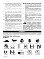
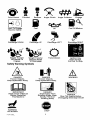


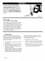

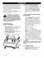

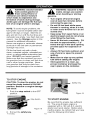
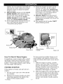


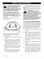
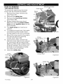
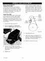
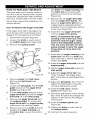

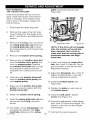
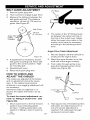

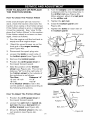
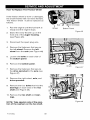


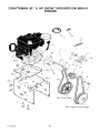
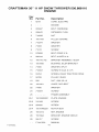
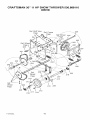
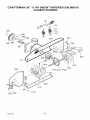

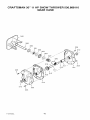
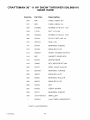
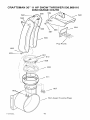


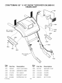
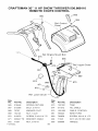


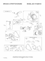

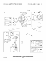
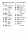

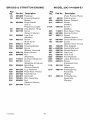
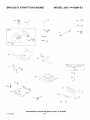
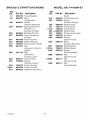


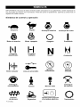

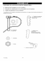

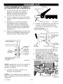


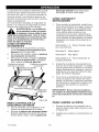
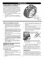


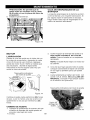


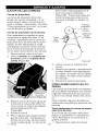
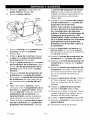
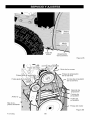
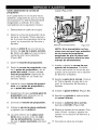
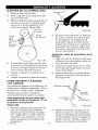
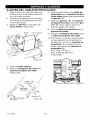


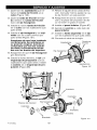


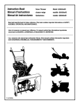
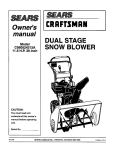
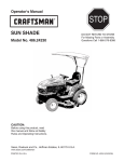
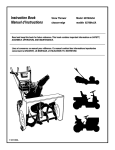
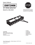
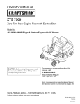


![CRRFTSMRN °] - at snowblowerguide.com](http://vs1.manualzilla.com/store/data/006202620_1-711fb90bb2c79d693479b4ac54c29ad0-150x150.png)