1
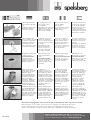
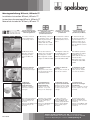
Montageanleitung IBTronic, IBTronic-TT
Installation Instruction IBTronic, IBTronic-TT
Instructions de montage IBTronic, IBTronic-TT
Manual de instalación IBTronic, IBTronic-TT
Einsatz im Ortbeton (Installation auf der Baustelle)
und im Fertigteilwerk
Application in-situ concreting
(installation at the
construction place) and in
pre-fabricated elements
Usage dans le béton (sur
le chantier) ou en usine de
préfabrication
Instalación en obra o en
paneles de hormigón
prefabricado (en fábrica)
1. Gehäuse einmessen
1. Measuring of the box
1. Positionner le boîtier
1. Posicionar la caja
2. Rohreinführungen
mit Profizange lochen
2. Punching of the entries
with the professional
pliers. Holes 2-3 mm
smaller than the overall
diameter of the conduit.
2. Dégager les entrées
prédéfonçables avec la
pince
2. Abrir las entradas con
la punzonadora. Los
agujeros deben de ser
2-3 mm. más pequeños
que el diámetro externo
del tubo.
2.1 Membran mittels
Weitedorn aufweiten.
2.1 Use the reamer to
enlarge the entry before
inserting the conduit.
2.1 Adapter l’orifice de
la membrane grâce au
« doigt élargisseur »
2.2 Integrated conduit
stopper for M25 and M32.
2.2 Butée d’arrêt intégrée
pour tube M25 et M32
2.1 Utilizar el punzón
para ampliar el agüjero
realizado con la
punzonadora antes de
insertar el tubo.
2.2 Integrierte Rohrstopper für M25 und
M32.
2.2 Incluye tope para
entrada de tubos M25
y M32.
M1-710-01
3. Montage Ortbeton
Gehäusefrontteil auf
der Schalung befestigen
3. Installation in-situ
concrete
fixing of the front on the
wooden shuttering by use
of aluminium nails.
3. Mise en œuvre sur
chantier.
Fixer la partie frontale de
la boîte sur la banche
3. Instalación en obra
Fijar la parte frontal
sobre panel de madera
con clavos de aluminio
3.1 Montage
Fertigteilwerk /
Farmacell®-Platte
Heißkleber auftragen
und auf der Schalung
befestigen
3.1 Installation prefabrication / of the
Farmacell®-Plate
Coating of hot melt
adhesive on top and
fixing on the shuttering.
3.1 Montage en usine
ou panneau Farmacell®
Enduire la partie frontale
du boîtier de colle chaude
et fixer le boîtier sur le
coffrage
3.1 Intalación en
paneles de hormigón
prefabricado
Pegar con adhesivo especial
la parte superior de la caja
al molde
4. Verrohrung vornehmen
IBTronic EH100/145 4/8
Rohreinführungen bis
34 mm Ø
IBTronic-TT EH100/145 6/10
Rohreinführungen bis
34 mm Ø
4. Fixing of the conduits
IBTronic EH100/145 4/8
Conduit entries up to
34 mm Ø
IBTronic-TT EH100/145 6/10
Conduit entries up to
34 mm Ø
4. Mise en place des
canalisations (tubes) IB
Tronic EH100/145 4/8
conduits jusqu’à Ø 34mm
IBTronic TT EH 100/145
6/10 conduits jusqu’à
Ø 34mm
4. Fijación de los tubos
IBTronic EH100/145 4/8
Entradas de tubo de hasta
34 mm. Ø
IBTronic-TT EH100/145 6/10
Entradas de tubo de hasta
34 mm. Ø
Günther Spelsberg GmbH + Co. KG • Im Gewerbepark 1
D-58579 Schalksmühle • Tel.: 0 23 55 / 8 92-0 • Fax.: 0 23 55 / 8 92-299
e-mail: [email protected] • Internet: www.spelsberg.de
5. Grünen Bodendeckel
sicher aufrasten (EH 100
mm).
5. Securely fix the green
cover on the bottom
(H = 100mm).
5.1 Zweites Gehäuse mit
Kabelbinder diagonal
sichern (EH 145 mm).
5.1 Fixing of second box, for
additional space, by using
cable ties in diagonal
directions (H = 145mm)
6. Nach Aushärten des
Betons entschalen. Frontteil
mit Hammer ausschlagen.
6. After the concrete is
harden the shuttering
can be released. Reject the
front part of the box with
a hammer.
6.1 Ø 108 mm Auslass 4
Verbindungsstege mit
Messer durchtrennen und
mit Hammer ausschlagen.
6.2 Ø 120 mm Auslass mit
Lochfräser bohren.
6.3 Fermacell®-Platte
Auslassöffnung mit
Lochfräser bis max. Ø
100 mm schneiden (evtl.
Oberfläche glätten)
6.1 Ø 108 mm outlet
anstatt exhaust hole.
Release 4 connection
bars with a knife and
reject with a hammer.
6.2 Ø 120 mm outlet
must be drilled with a
cutter.
6.3 Fermacell®-Plate
Open up the outlet with
a cut out of max. Ø
100 mm (possibly surface
polishing).
5. Bien fixer le couvercle
vert (H: 100mm)
5.1 Sécuriser
diagonalement le second
boîtier grâce aux fixes
câbles (H:145)
5. Asegurar la fijación de
la tapa verde en la base
de la caja (H= 100mm).
5.1 Para la fijación de la
segunda caja, (para
espacio adicional) utilizar
abrazaderas colocadas en
diagonal (H = 145mm)
6. Décoffrer lorsque le
béton est sec. Enlever la
partie avant du boîtier
par un coup de marteau.
6. Una vez endurecido el
hormigón, retirar la parte
frontal con un golpe de
martillo.
6.1 Ø 108 mm avec 4
connexions. A séparer avec
un couteau et défoncer
avec un marteau.
6.1 Agüjero de salida de
Ø 108 mm. Recortar los
4 topes con un cúter y
golpear con un martillo.
6.2 Ø 120 mm découper
avec une fraise.
6.2 Abrir hueco de
Ø 120 mm con una fresa
6.3 Panneaux Fermacell®
Découper avec une scie
cloche Ø max 100mm (si
nécessaire ébavurer)
6.3 Fermacell®-Plate
Abrir hueco con una fresa
de un máximo de Ø
100 mm (se puede pulir)
7. IBTronic-TT Einsatz
elektronischer Sicherheitstransformators bis max.
150W (z.B. Osram
Halotronic HTM Mouse).
Sicherheitstransformator
anschließen und in das
IBTronic-TT Gehäuse
Einbauhöhe 100/145 mm
einschieben. Sekundärseitig wärmebeständige
Anschlussleitung verwenden (z.B. N2GMH 2G).
7. IBTronic-TT
application electronic
security transformer up to
max. 150W (e.g. Osram
Halotronic HTM Mouse).
Installation of the security
transformer and insertion
in the IBTronic-TT tunnel
Installation Height 100/145
mm. On the secondary side
only use of heat resisting
connection cable (e.g.
N2GMH 2G).
7. IBTronic-TT transfo
de sécurité max 150W
(par exemp.: Osram Halotronic HTM Mouse).
Connecter le transfo au
primaire, le glisser dans
le boîtier IB Tronic TT
(dimensions 100/145mm)
Connecter le secondaire
du transfo avec un câblage
approprié (par exemp.:
N2GMH2G)
7. IBTronic-TT Montar
transformador electrónico
de seguridad de hasta un
máximo de 150 W (v.gr.
Osram Halotronic HTM
Mouse). Colocar el
transformador de
seguridad en el túnel
IBTronic-TT. Altura:
100/145 mm. Utilizar
únicamente cable de
conexión resistente al
calor (v. gr. N2GMH 2G).
7.1 VDE geprüfte Leuchten
nach DIN EN 60598 (VDE
0711) sowie mit F oder
MM-Kennzeichnung bis
max. 50W und max. Einbauhöhe NV Leuchten 75 mm/
120 mm, HV Leuchten
80/125 mm einbauen.
7.1 Assembling of VDE
tested luminares acc. to
DIN EN 60598 (VDE 0711),
marked with F or MM up
to max. 50W and max.
installation height low
voltage luminares 75 mm/
120 mm, high voltage
luminares 80/125 mm.
7.1 Mise en place des
luminaires (spots) selon
DIN EN 60598 (VDE 0711)
ou selon références F ou
MM – max 50W et d’une
hauteur d’encastrement
max. 75/120mm (TBT), ou
80/125mm (BT)
7.1 Instalación de
luminarias certificadas
VDE según DIN EN 60598
(VDE 0711), así como las F
o MM hasta 50 W. y con
altura máxima de 75/120
mm. para luminarias de
baja tensión y de 80/125
mm. para las de alta
tensión.
Beim Betoniervorgang darauf achten, dass die Gehäuse vollständig vom Beton eingeschlossen werden.
When pouring the concrete please ensure the boxes are completely cocered/surounded by concrete.
Lors du coulage du béton, bien s'assurer que les boîtiers sont intégralement pris dans le béton
Durante el hormigonado, recordar que las cajas deben estar completamente rodeadas de hormigón
M1-710-01
Günther Spelsberg GmbH + Co. KG • Im Gewerbepark 1
D-58579 Schalksmühle • Tel.: 0 23 55 / 8 92-0 • Fax.: 0 23 55 / 8 92-299
e-mail: [email protected] • Internet: www.spelsberg.de