1
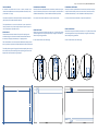
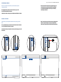
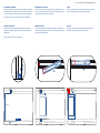
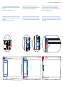
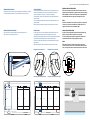
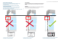
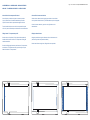
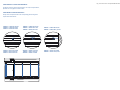
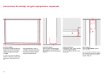
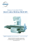
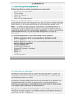
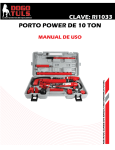
M32-2
Instrucciones de montaje
Assembly instructions
Pag. 1 - Instrucciones de montaje MOVIGLASS M32-2 Rev.H
TOMA DE MEDIDAS
Se tomarán las medidas luz del hueco a cubrir, tomando como
referencia las medidas menores entre las paralelas verticales (H = Alto)
y horizontales (L = Largo).
FIJAR MARCOS SUPERIORES
Sacar los niveles de emplazamiento del cerramiento, atornillar el conjunto
de perfil U desnivel superior junto con el marco superior (van unidos entre sí,
mediante distanciadores), a través de taladros realizados por fábrica.
FIJAR MARCOS INFERIORES
Sacar los niveles de emplazamiento del cerramiento, atornillar el conjunto
de perfil U desnivel inferior junto con el marco inferior (van unidos entre sí,
mediante distanciadores), a través de taladros realizados por fábrica.
Las cotas se expresarán en milímetros teniendo en cuenta que cualquier
perfil o pilar que se instale alterará la cota final.
En el caso de llevar marcos laterales, ver hoja de complementos.
En el caso de llevar marcos laterales, ver hoja de complementos.
FIXING TOP FRAME
Get the level at the place of install, screw the set of “U” profile & Top frame
(Its came together from factory with expanders), through the drills already
done in factory during production.
FIXING LOWER TRACK
Get the level at the place of install, screw the set of “U” profile & Lower Track
(Its came together from factory with expanders), through the drills already
done in factory during production.
In case of lateral frames, see add-on page
In case of lateral frames, see add-on page
Tener especialmente en cuenta la solidez de la parte superior del
hueco, pensando en el perfecto anclaje del marco superior ya que el
cierre va totalmente suspendido de este.
MEASURING UP
The measurements must be taken of the span of the opening to be
enclosed, taking as a reference the smallest measurements between
the vertical (H = Height) and horizontal (L = Length) parallels.
These measurements are to be expressed in millimetres, bearing in mind
that any member or pillar that is installed will alter the final measurement.
The solidity of the top part of the gap will be taken especially into account,
with a view to the perfect anchorage of the top frame, given that the full
weight of the enclosure must be supported by it.
NIVELAR MARCO SUPERIOR
Nivelar con la ayuda de una llave Allen 5 y los distanciadores que lleva
incorporado el marco.
Es muy importante el perfecto nivel de este marco, ya que es la
base del funcionamiento del sistema.
Pag. 2 - Instrucciones de montaje MOVIGLASS M32-2 Rev.H
Nota: Para reforzar la zona donde se pliegan las hojas y se
concentra todo el peso, fijar lateralmente según dibujos
con 4 tornillos DIN 7981 de 4,8 X 16 mm por el exterior y
4 tornillos por el interior.
Limpiar bien el interior de las guías de rodadura para eliminar las virutas.
LEVELING OF TOP FRAME
Using a allen key and the expanders included on the top track, get a perfect
level.
It is very important get a perfect level of such frame, because is the main
issue of a properly operation of the system.
Note: To enforce the area where the leaves are folded and all
is all the weight, fix lateraly as per figure using DIN 7981,
4.8 X 16 mm screws (4 indoor side and 4 screws outside side).
Clear well the inside part of guides where will go the running gear to avoid
scrap inside.
69 mm
Pag. 3 - Instrucciones de montaje MOVIGLASS M32-2 Rev.H
NIVELAR MARCO INFERIOR
Nivelar con la ayuda de una llave Allen 5 y los distanciadores que lleva
incorporado el marco. La galga nos dará la medida que debe quedar
entre el marco inferior y el marco superior (el cual ya está nivelado).
NUMERACIÓN DE LAS HOJAS
Las hojas están numeradas según el sentido de plegado, de manera
que si el cerramiento pliega a la izquierda, será de izquierda a derecha
el sentido de numeración que lleven las hojas.
1ª HOJA
Introducir la primera hoja por el cajeado de los marcos y llevarla al
extremo de plegado hasta que se alcance el tope superior.
NUMBER OF PANELS
The panels are numbered according to the direction in which they fold
away, which means if they are stacked on the left the numbering on the
panels will run from left to right.
1st PANEL
Inserting the first panel in the mortising of the frame and slide it to
the stacking end until it comes up against the top stop.
En el caso de llevar marcos laterales ver hoja de complementos.
LEVELING LOWER TRACK
Using a 5 allen key and expanders included on the top track, get a
perfect level. The pipe supplied as interior size must to be the same
after get level.
In case of lateral frames, see the add-on page.
Galga
Pag. 4 - Instrucciones de montaje MOVIGLASS M32-2 Rev.H
Presentar el eyector sin atornillar y comprobar el eje de la rueda
de apertura de la primera hoja, debe hacer contacto con el ala larga
del eyector.
Quitar el eyector para continuar la instalación.
Fijar el tope en los taladros ubicados en el marco superior.
Comprobamos el nivel de la hoja y ubicamos el tope inferior para a
continuación fijar este, en el taladro del marco inferior.
Fijada la primera hoja, colocarla a 90° con respecto a los marcos y
atornillar el retenedor en el marco superior para dejar la hoja
perpendicular a los marcos. Es muy importante poner este tope para el
buen funcionamiento del cerramiento.
Display the ejector without screwing and verify the axe of the wheel
of opening of the first leaf. It must make contact with the large wing
of the ejector.
Take out the ejector to continue the installation.
Make up the stop in the holes located to that end in the top frame.
Check the level of the panel and locate the bottom stop and then fit it
into place, using the holes located to that end in the bottom frame.
Having fitted the first panel, set it at 90° to the frame and make up the
retainer onto the top frame so that the panel hangs perpendicular to the
frames. It is very important to fit this stop to ensure the correct operation
of the enclosure.
90°
Pag. 5 - Instrucciones de montaje MOVIGLASS M32-2 Rev.H
INTRODUCCIÓN DE LAS HOJAS
Introducir las hojas en orden inverso al plegado. Comenzando por la hoja 4,
a continuación la hoja número 3 y terminando por la hoja número 2.
INSERTING THE REST OF THE PANELS
Insert the panels in reverse folding order. Start with panel no. 4,
then panel no. 3 and finally panel no. 2.
TAPAS DE MARCOS
Colocar la tapa del eyector en el perfil superior y la tapa inferior en su
marco correspondiente. Tener en cuenta la posición del eyector
según el plegado de las hojas. Comprobar el plegado y
funcionamiento de las hojas, accionado el pomo para desbloquear
la primera hoja.
Una vez realizada esta operación, limpiar las posibles virutas que se
hayan formado.
NOTA: Colocar taco última hoja, para fijar la posición de la misma.
INSTRUCCIONES DE INSTALACIÓN
El eje de la rueda de apertura debe de hacer contacto con el ala
larga del eyector. (Desplazar el conjunto rueda si fuese necesario)
Puede desplazar el eyector hacia la derecha o la izquierda dentro
del mecanizado hasta que ajuste en el ala larga del eyector.
FRAME COVERS
Fit the ejector cover to the top member and the bottom cover in its
corresponding frame. Bear in mind the position of the ejector,
depending on the folding of the panels. Check the folding and operation
of the panels by working the knob to unblock the first panel.
INSTALLATION INSTRUCTIONS
The axle of the opening wheel must make contact with the long
wing of the ejector. (Move the wheel sets if required)
It can move the ejector towards the right or the left inside the
mechanized until it fits in the long wing of the ejector.
Once this has been done clean off any possible filings that may have
been formed.
NOTE: Place plug last leaf, to determine the position of the same.
2
3
4
Plegado hacia la izquierda
Plegado hacia la derecha
Fold away and stack to the left
Fold away and stack to the right
1
2
3
4
NOTA
Cuando el cerramiento en un lado lleva 2 eyectores, el primero en
colocar es el que tiene la entrada de las ruedas más alta. Y el
segundo en colocar el de la entrada más baja.
NOTE:
When the enclosure, has in the side two ejectors, the first in
install over the top frame is the one that has the wheel entrance
lower, and the second the one that has this entrance more above.
Pag. 6 - Instrucciones de montaje MOVIGLASS M32-2 Rev.H
INSTRUCCIONES DE INSTALACIÓN
Si las hojas no estan correctamente niveladas y se abren en la parte
inferior o superior, es porque los marcos no están nivelados
en ese punto concreto.
Se solucionara nivelando el marco superior en toda su longitud.
EJE DE BISAGRA
Prestar mucha atención en que el eje de bisagra actue sobre la bisagra en
paralelo, y al mismo tiempo, tanto en la parte superior como inferior de
la hoja.
INSTALLATION INSTRUCTIONS
If the panels are not correctly levelled and there are gaps between
them, either at the bottom or the top, it is because they have not
been correctly levelled at this specific point.
This problem can be solved by levelling the top frame along its whole length.
HINGE PIN
Make absolutely sure that the hinge pin acts on the hinge in parallel and,
at the same time, at both top and bottom of the panel.
Las hojas no cierran en su parte inferior.
The panels do not close at the bottom
Las hojas no cierran en su parte superior.
El marco esta perfectamente nivelado en toda su longitud.
The panels do not close at the top
The frame is perfectly level along its whole length.
Pag. 7 - Instrucciones de montaje MOVIGLASS M32-2 Rev.H
COMPLEMENTOS : U COMPENSACIÓN + MARCOS LATERALES
ADD-ONS: ”U” COMPENSATOR PROFILE + LATERAL FRAMES
Colocación de U de compensación lateral.
Colocación de los marcos laterales
Una vez fijados y nivelados el conjunto de marcos superiores
(que van unidos entre sí mediante distanciadores), atornillar
el perfil U desnivel inferior comprobando desagües inferiores.
Utilizar el marco lateral a modo de galga, para nivelar el marco inferior
con la ayuda de la llave Allen de 5 y los distanciadores que lleva integrados.
Tomar la medida del hueco entre la U de compensación superior
e inferior y cortar la U lateral para colocarla entre las us horizontales.
Colocar los marcos laterales y ponerlos a nivel, fijándolos con los
distanciadores.
Fitting Lateral ”U” compensator profile.
Fitting the lateral frames
One time the set of top frame (U+Track joined with expanders) is
leveled and fixed, screw the lower ”U” compensator checking the
outside wateroutlets.
Using the lateral frame to get the distance and level the bottom track
(with the 5 key allen and expanders included).
Get the size of light gap between top and bottoom “U” compensator,
cut the lateral “U” compensator to the proper size till you can put
between horizontal “U” compensators.
Lu
Put the lateral frames and get level, fixing with its own expanders.
Pag. 8 - Instrucciones de montaje MOVIGLASS M32-2 Rev.H
COMPLEMENTOS: JUNTAS TRANSPARENTES
Por último, colocar las juntas transparentes en sus hojas correspondientes,
fijandolas con unas gotas de silicona neutra.
COMPLEMENTS: TRANSPARENT SEALS
Finally, fit the transparent seals to the corresponding panels, fixing them
in place with neutral silicon.
JUN004 --> Vidrio de 10 mm
JUN006 --> Vidrio de 8 mm
JUN013 --> Vidrio de 6 mm
JUN009 --> Vidrio de 10 mm
JUN003 --> Vidrio de 8 mm
JUN005 --> Vidrio de 6 mm
JUN004 --> Glass of 10 mm
JUN006 --> Glass of 8 mm
JUN013 --> Glass of 6 mm
JUN009 --> Glass of 10 mm
JUN003 --> Glass of 8 mm
JUN005 --> Glass of 6 mm
JUN010 --> Vidrio de 10 mm
JUN008 --> Vidrio de 6 y 8 mm
JUN010 --> Glass of 10 mm
JUN008 --> Glass of 6, 8 mm
Polígono Serrallo, nave 36
12100 Grao de Castellón de la Plana
Castellón, España
Telf. +34 964 737 016
Fax. +34 964 737 184