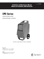
1
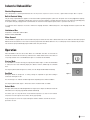
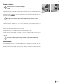
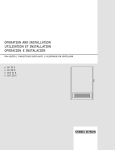
Installation and Maintenance Manual
Manual de Instalación y Mantenimiento
Item #: 405037
Rev Date: 2015-06-01
EPD Series
Industrial Dehumidifier
Déshumidificateur industriel
Industrial Dehumidifier
Deshumidificador industrialDeshumidificador industrial
Read and Save
These
Instructions
Lisez et
conservez ces
instructions
Lea y guarde
estas
instrucciones
EPD150LR • EPD180CR • EPD190LR • EPD250CR
Operating Instructions
Guide d'utilisation
Instrucciones de uso
United States
10048 Industrial Blvd., Lenexa, KS, 66215
Tel.: 800.747.1762 • Fax: 800.487.9915
Canada
50 Kanalflakt Way, Bouctouche, NB, E4S 3M5
Tel.: 800.565.3548 • Fax: 877.747.8116
Fantech Ltd. 1-800-565-3548
1
3
5
405037
fantech
2
Note
Warning/
Important
note
Information
Technical
information
Practical tip
WARNINGS
ADVERTENCIAS
Plug into a grounded 3 prong outlet
Conecte a un contacto de pared de conexión a tierra de 3 terminales.
Do not remove ground prong.
No quite la terminal de conexión a tierra.
Do not use and adapter.
Do not use an extension cord.
Failure to follow these instructions can result in death, fire, or electrical
shock
WARNING: The dehumidifier uses a high pressure refrigerant system and
high voltage circuitry which could present a health hazard resulting in
death, serious bodily injury, and/or property damage. Only qualified service people should service this unit.
CAUTION: Do not operate unit without the front hood secured in place.
The serial data plate is located on the underside of the dehumidifier. For
service information contact 1-800-565-3548.
fantech
No use un adaptador.
No use un cable elétrico de extensión.
No seguir estas instrucciones puede ocasional la muerte, incendio o choque
eléctrico.
ADVERTENCIA: El deshumidificador utiliza un sistema de líquido refrigerante de alta presión y un circuito eléctrico de alto voltaje que podrían
resultar en daños materiales, peligro para la salud, lesiones corporales
graves, e incluso la muerte. Sólo personal cualificado debe dar servicio a
esta unidad.
PRECAUCIÓN: No utilice la unidad hasta haber asegurado la cubierta frontal en posición cerrada.
La placa serial está situada en el superficie inferior del deshumidificador.
Consulte con el número 1-800-565-3548 para másinformación sobre
servicio.
ircuit is required. The dehumidifier draws approx. 8 amps at
0°F, 60% RH. If used in a wet area, a ground fault interupter (GFI) is required.
Hour
Button
(Fig.
4)
For your
safety and
protection
this appliance is manufactured
Press
HOURS
button
when
thecord.
dehuwith a the
grounded
plug
on its
power
The power cord must
3
midifier
cannot
be
plugged
in
and
the
be plugged into a properly groundedhour
receptacle. If a groundmeter
needs todoes
be read.
Thehave
digitalone
hour
ed receptacle
not exist,
installed by a certified
meter
will
display
the
last
saved
cumulative
electrician. Do not cut or remove the grounding prong on the
Built in Electrical Safety
time
forcord
ten seconds.
power
plug if equipped. We recommend thatFig.
this 4electriFor your safety and protection this appliance is manufactured
cal
circuit/receptacle
operate
under
a
separate
breaker or
Electrical
with a grounded
plugRequirements
on its power cord. The power cord must
fuse.
Forinto
115V
common grounded
outlet Ifonaa ground15 amp circuit is required.
If used
in a wet area, a ground fault interrupter (GFI) is required.
Battery
Replacement
e plugged
a operation,
properly agrounded
receptacle.
If
an
extension
cord is required, it must have a minimum of
d receptacle does not exist, have one installed by a certified
Built
in
Electrical
Safety
14
gauge
conductors
if 25 feet long or less and 12 gauge
lectrician. Do not cut or remove the grounding prong on the
For your safety and protection this appliance is manufactured with a grounded
plug on itsifpower
cord.than
The power
cordlong.
must be plugged into a properly
conductors
greater
25 feet
ower cord plug if equipped. We recommend that this electrigrounded receptacle. If a grounded receptacle does not exist, have one installed by a certified electrician. Do not cut or remove the grounding prong
al circuit/receptacle operate under a separate breaker or
on the power cord plug if equipped. We recommend that this electrical circuit/receptacle operate under a separate breaker or fuse.
use.
Water Removal
B
Industrial Dehumidifier
WARNING
The dehumidifier
is equipped
an internal
condensate
If an extension
is required,
it must
have aa minimum
of of
14 gauge conductors
if 25 feet long
or less andwith
12 gauge
conductors
if greater pump
than 25
an extension
cord iscord
required,
it must
have
minimum
to
remove
the
water
that
is
collected
from
the
air.
This
allows the
long.
4 gaugefeet
conductors
if 25 feet long or less and 12 gauge
water to be pumped 20 feet with the attached hose. If the water
onductors if greater than 25 feet long.
Electrical Shock Hazard
Limitations of Use
needs to be pumped more than 20 feet above the unit, a second
Plugmust
into abe
grounded
prong
outlet.
Disconnect
power
before
replacing
battery.
Temperature: 4°C to 35°C (40°F to 95°F)
pump
addedsupply
to3relay
the
water.
The condensate
pump
Water Removal
Relative Humidity: 20 to 80%
automatically
purges
for
20
seconds
every
four
minutes.
Do not remove
prong.
Failure
to followground
these instructions
can result in death,
The dehumidifier is equipped with an internal condensate pump
fire, or electrical shock.
Do not use an adapter.
o remove Water
the water
that is collected from the air. This allows the
Removal
water to beThe
pumped
20
feet
with
the
attached
hose.
If
the
water
dehumidifier is equipped with an internal condensate pump to remove the water that is collected from the air. This allows the water to be pumped
Disconnect dehumidifier from power supply. The hour meter uses
eeds to be
than 20
feetIf above
theneeds
unit,toa be
second
20pumped
feet with more
the attached
hose.
the water
pumped more than 20 feet above the unit, a second pump must be added to relay the water.
a battery backup for display when the dehumidifier is unplugged
ump mustThe
becondensate
added topump
relayautomatically
the water. The
condensate
pump
Place dehumidifier inside area to be dried. Make sure all winpurges
for 20 seconds
every four minutes.
and the hour button is depressed. To change the battery, it is necutomatically purges for 20 seconds every four minutes.
dows and doors are closed to the outside and seal off the wet
essary to remove the four (4) screws from the control panel.
area from any unaffected areas. Route condensate hose into
Disconnect the old battery and replace with new battery. Replace
a drain, or a very large container. Press the On/Off button
control panel and screws. Do not overtighten screws.
(Fig. 1) to activate the dehumidifier.
D
a
a
e
D
co
OPERATION
D
W
tr
th
u
th
cy
OPERATION
Operation
lace dehumidifier inside area to be dried. Make sure all winCycle
Place dehumidifier inside area to be dried. Make sure all windows and Defrost
doors are closed
to the
Power
Button
(Fig.
1)
ows and doors are closed to the outside and seal off the wet
When
iceinto
builds
up or
on the coils, a thermistor activates the elecoutside and seal off the wet area from any unaffected areas. Route condensate
hose
a drain,
The
dehumidifier
is
turned
on or off by
rea from any unaffected areas. Route condensate hose into
tronic control and defrost light. The compressor is turned off by
a very large container. Press the On/Off button (figure 1) to activate the dehumidifier.
pressing
the
power
button.
When the
drain, or a very large container. Press the On/Off button
the thermistor temperature measurement. The blower will contindehumidifier
is
started,
the
hour
meter will
Fig. 1) toStart-up
activate the
dehumidifier.
ue to run, causing air to flow through the evaporator coil and melt
Mode
display the cumulative hours.
theWhen
ice. When
the ice is melted, the thermistor will end the defrost
The dehumidifier is turned on or off by pressing the power button (figure 1).
the dehumidifier
Figure 1
Fig. 1
cycle and
thecumulative
compressor will be started.
is started, (Fig.
the hour1)meter will briefly display the software version #, followed
by the
Power Button
hours.
The dehumidifier
is turned on or off by
ressing the power button. When the
Defrost Indicator (Fig. 5)
Pressing the power button during the first minute, the unit will go into OFF Mode immediately.
ehumidifier
is started, the hour meter will
The defrost indicator will light to indicate the
isplay the cumulative hours.
dehumidifier is in defrost cycle. During this
Run Mode
Figure 2
the compressor
Fig.
1
During Run Mode the compressor is running causing the evaporator period,
to get cold
resulting in is not running.
Fig. 5
(1)
condensate forming on the coil.
The unit will stay in run mode for variable length of time depending on the ambient conditions.
Pressing the power button (figure 1) will send the unit in shut down mode (see below)
Defrost Mode
During the defrost mode, the indicator light will turn on (figure 2), the compressor will be off and the fan
will continue to run. The pump purge will be activated automatically.
The defrost cycle runs every 45 minutes in cool ambient temperature, less often in warm ambient
temperature and the length of time in defrost will vary appropriately.
Heavy frosting on the coil can be expected during low ambient conditions and will not affect the
operation of the unit.
fantech
D
(1)
T
d
p
4
Shut Down Mode
Pressing the power button after the first minute of operation will initiate a shut-down mode. This mode
Pump
(Fig. 2)
will last 15 minutes and will maintain the operation of the fan and purge pump
to insurePurge
all waterButton
is
In
normal
operation,
the
pump
will automatremoved from the unit prior to moving or storing. Pressing the power button at any time during the shut
ically
empty
the
reservoir.
Pressing
this butdown mode will immediately shut down the unit and bypass the remainder of the shutdown mode. The
ton allows manual emptying of the reservoir.
unit must be purged by pressing the purge button if bypassing the shutdown mode to avoid water
Press once, and the pump will operate for
overflow.
20 seconds. Press and hold the button and
WARNING
the pump will activate for 30 seconds.
The display will change during shutdown mode to a countdown timer that will indicate the
Figure 3
Always manually purge the water reservoir
time remaining before the unit shuts completely off.
before transport or storage. Turn off the
Electrical Shock Hazard
Plug into a grounded 3 prong outlet.
Functions
Do not remove ground prong.
power and allow the plugged in dehumidifier
to rest 5 minutes before the final purge.
Fig. 2
Digital Hour Counter (Fig. 3)
Do not use an adapter.
Do not use an extension cord.
Loss of Power Recovery Function
The counter will accumulate and display the total running hours
of the unit in 1/10 of an hour.
Failure
to follow
these
instructions
can
result
In case
of a loss
of power,
the last run
state
(ON inordeath,
OFF) will be maintained when the power is
Fig. 3
fire, or
electrical shock.
restored.
Pump Purge Function
Electrical
Requirements
In normal operation, the pump
Figure 4
will automatically empty the reservoir. Pressing the purge button
Venting / Ducting (Fig. 6)
For 115V
operation, a common grounded outlet on a 15 amp
(figure 3) runs the pump for 1 minute allowing manual emptying of the reservoir.
The
pump purge
Hour
Button
4)
Twin rear
outlets(Fig.
can accommocircuit iswill
required.
The dehumidifier draws approx. 8 amps at
function in all modes as long as the unit is plugged in.
Press
the
HOURS
button
when
the dehudate
two
individual
5”
ducts
or one
80°F, 60% RH. If used in a wet area, a ground fault intermidifier
cannot
be
plugged
in
and
the hour
10”
lay
flat
duct
to
be
attached.
rupter (GFI)
required.
HourisMeter
Display
meter
needsfortowarm
be read.
The
hour
This allows
dry air
to digital
be
The cumulative hours will be displayed during normal operation. If the unit is off (even unplugged)
meter
willinto
display
the last
saved cumulative
directed
different
areas.
pressing
the hour button
(figure 4) will also display the accumulative hours briefly.
Built in
Electrical
Safety
time for ten seconds.
Fig. 4
For your safety and protection this appliance is manufactured
Venting /plug
Ducting
with a grounded
on its power cord. The power cord must
Fig.
Figure
5 6
Twin rear
(figuregrounded
5) canVenting
accommodate
two If
individual
10” lay flatReplacement
duct to be Fig. 8
be plugged
into outlets
a properly
receptacle.
a ground/ Ducting
(Fig.
6)5” ducts or oneBattery
attached.
This not
allows
for warm
dry
air
tooutlets
be directed
different areas.
Twin
rearinstalled
can
ed receptacle
does
exist,
have
one
byaccommoainto
certified
two individual 5” ducts or one
electrician. Do not cut or removedate
the
grounding
prong
on
the
10” lay flat duct to be attached.
power cord plug if equipped. We This
recommend
that
this
electriallows for warm dry air to be
directedainto
different areas.
cal circuit/receptacle operate under
separate
breaker or
Air Filter (Fig. 7)
fuse.
The air filter should be checked regularly. Operating the dehuFig. 6
If an extension cord is required, it must have a minimum of
midifier with a clogged filter will reduce efficiency. The filter can be
Air Filter
14 gauge conductors if 25 feet long or less and 12 gauge
vacuum cleaned to remove dust. To access the filter media, slide
The air filter should be checked regularly. Operating the dehumidifier with a clogged filter will reduce
conductors if greater than 25 feetMaintenance
long.
the filter frame upStorage
until it clears
the dehumidifier
cabinet. Remove
Electrical
Shock
Hazard
efficiency. To access the filter, slide the filter frame up until it clears the dehumidifier cabinet Freezing
temperatures
andand
biological
growth Reverse
must be considered
the filter media from behind
the frame
vacuum.
pro(figure 6). Reverse procedure Air
to re-install
the filter
filters
should
be supply
before
storing
the outlet.
dehumidifier.
Thebattery.
dehumidifier should be
Filter (Fig.
7) into the dehumidifier. Metal
Plug
into
a
grounded
3
prong
Disconnect
power
before
replacing
cedure
to
re-install
the
filter
and
frame
into
the
dehumidifier.
flushed with a biofungicide before storing. When storing the unit,
Water Removal
MaintenanceWARNING
Maintenance
washed with soap and water, and
filters
should
be replaced.
Thepaper
air filter
should
be checked
regularly. Operating the dehuDo not remove ground prong.
Failure
thesethat
instructions
can
resultfrom
in death,
ensure
water has been
removed
the reservoir and
with a clogged
filter will reduce
can beto follow
The dehumidifier is equipped with midifier
an internal
condensate
pumpefficiency. The filter
hose.
This will prevent damage caused by freezing temperatures
fire,Fig.
or
electrical
shock.
vacuum
cleaned
to remove dust. To access the filter media,
slide
Paper
filter
size
is
a
nominal
12"
x
12"
x
1"
7
Do not use an adapter.
to remove the water that is collected
from the air. This allows the
and to prevent biological growth. Use the pump purge button to
the filter frame up until it clears the dehumidifier cabinet. Remove
remove water and biofungicide chemicals from the dehumidifier.
water to be pumped
20
feet
with
the
attached
hose.
If
the
water
the
filter
media
from
behind
the
frame
and
vacuum.
Reverse
proOperating the unit without the filter in place will cause reduced efficiency
due
to
dirty
coils
and
Disconnect dehumidifier from power supply. The hour meter uses
cedure
to re-install
the
filteraand
frame into the dehumidifier.
needs to be pumped
more
than
20
feet
above
the
unit,
second
increase the frequency of internal coil cleaning.
Stacking
a battery backup for
display(Fig.9)
when the dehumidifier is unplugged
pump must be added to relay the water. The condensate pump
The
dehumidifiers
can
stackedthe
on battery,
top of each
Figure 6
Fig. 7
and
the
hour
button
is
depressed.
To be
change
it isother.
nec-The
automatically purges for 20 seconds every four minutes.
wheels from the upper unit must be resting in the cradle of
essary to removethethe
four
fromMORE
the control
panel.
lower
unit.(4)
DOscrews
NOT STACK
THAN TWO
HIGH.
Stacking
Disconnect the old battery and replace with new battery. Replace
Fig.
9
The dehumidifiers can be stacked on top of each other (figure 7). The wheels from the upper unit
control panel and screws. Do not overtighten screws.
OPERATION
must be resting in the cradle of the lower unit. DO NOT STACK MORE THAN TWO HIGH.
Place dehumidifier
inside area to be dried. Make sure all winDefrost Cycle
Battery Replacement
dows and doors are closed to the outside and seal off the wet
When ice builds up on the coils, a thermistor activates the elecDisconnect power
supply
before
replacing battery.
area from any unaffected
areas.
Route
condensate
hose into
tronic control and defrost light. The compressor is turned off by
Failure
to follow
these instructions
can result
in death,
fire, or electrical shock
a drain, or a very
large
container.
Press the
On/Off
button
the thermistor temperature measurement. The blower will contin(Fig. 1) to activate the dehumidifier.
ue to run, causing air to flow through the evaporator coil and melt
Disconnect dehumidifier from power supply. The hour meter uses a battery backup for display when the
ice. When
the ice is melted, the thermistor will end the defrost
dehumidifier is unplugged and the hour button is depressed. To change the battery, the
it is necessary
to remove
Cleaning
cycle
and
the
compressor
will7 be started.
PowertheButton
(Fig.from
1) the control panel. Disconnect the old battery and replace with new battery.Service
Figure
four (4) screws
The dehumidifier
ispanel
turned
on orDooffnotby
Replace control
and screws.
overtighten screws.
A qualified refrigeration technician must service all refriger-
Cleaning
pressing the power button. When the
dehumidifier
is started, the hour meter will
fantech
display the cumulative hours.
WARNING Defrost Indicator
WARNING
ant leaks.
(Fig.
5)
WARNING:
Thetodehumidifier
uses a high pressure refrigerant
The defrost indicator
will light
indicate the
system
and
high
voltage
circuitry
dehumidifier is in defrost cycle. During this which could present a health
hazard resulting in death, serious bodily injury, and/or property
Venting / Ducting (Fig. 6)
Twin rear outlets can accommodate two individual 5” ducts or one
10” lay flat duct to be attached.
Disconnect power supply before cleaning
This allows for warm dry air to be
into different
areas.
Failure to follow these instructionsdirected
can result
in death,
fire, or electrical
Cleaning
Fig. 8
5
shock
Fig. 6
External Cleaning
Use a non-flammable mild, non-abrasive soap and water solution. Wipe dry.
Maintenance
Figure 8
Storage
Internal Cleaning
Disconnect dehumidifier from power supply.Air Filter (Fig. 7)
The air filter should be checked regularly. Operating the dehumidifier with a clogged filter will reduce efficiency. The filter can be
Light cleaning: Remove the air filter and spray
evaporator coil with water.
vacuum cleaned to remove dust. To access the filter media, slide
the filter frame up until it clears the dehumidifier cabinet. Remove
filterfront
mediahood.
from behind
frameSpray
and vacuum.
pro-Close
Heavy cleaning: Remove two upper screwsthe
from
Openthehood.
waterReverse
at coils.
cedure to re-install the filter and frame into the dehumidifier.
hood and replace screws. (figure 8)
Fig. 7
Care must be taken to insure coil fins are not damaged, as damaged fins can restrict airflow
and reduce the unit's ability to produce water.
Freezing temperatures and biological growth must be considered
before storing the dehumidifier. The dehumidifier should be
flushed with a biofungicide before storing. When storing the unit,
ensure that water has been removed from the reservoir and
hose. This will prevent damage caused by freezing temperatures
and to prevent biological growth. Use the pump purge button to
remove water and biofungicide chemicals from the dehumidifier.
Stacking (Fig.9)
The dehumidifiers can be stacked on top of each other. The
wheels from the upper unit must be resting in the cradle of
the lower unit. DO NOT STACK MORE THAN TWO HIGH.
Fig. 9
Storage
Freezing temperatures and biological growth must be considered before storing the dehumidifier. To
prevent the biological growth, spray an evaporator cleaner on the coils and rinse into the drainage
system. You must also purge the excess liquid from the pump using the manual purge function to
prevent issues with freezing storage environments.
Cleaning
Troubleshooting
WARNING
Service
A qualified refrigeration technician must service all refrigerant leaks.
WARNING: The dehumidifier uses a high pressure refrigerant
system and high voltage circuitry which could present a health
hazard resulting in death, serious bodily injury, and/or property
The unit continually ices up:
Note that
iceservice
buildup
on the
evaporator
coil
damage.
Onlysome
qualified
people
should
service this
unit.
CAUTION:
not operate unit without the front hood secured in
is normal but airflow should
not be Do
blocked.
Electrical Shock Hazard
place.
Service
A qualified refrigeration technician must service all refrigerant leaks.
The Unit is NOT working:
• Is warm air blowing out the back of the unit? - No warm air, ambient
Plug into a grounded
3 prong
outlet.
Disconnect
power supply
before
cleaning.
The serial data plate is located on the underside of the dehumid• Has the breaker tripped? – Reset breaker Failure
temperature
low.service
Raiseinformation
temperature
supplementary
Do not remove
prong.
to followground
these instructions
can result
in death, may be too
ifier. For
contact with
1-800-565-3548.
fire, or electrical shock.
Do not use circuit?
an adapter.
• If in a wet area, is the unit plugged into a GFI protected
– Excessive
source.
moisture will trip GFI. Remove from area. External Cleaning
• Is the air filter clean and airflow unobstructed? – Clean filter. Unit should
Use a output
non-flammable
non-abrasive have
soap aand
clean of 10” clearance all around it.
• Is the unit being run off a generator? - Check
does notmild,
fluctuate
minimum
water solution to clean the dehumidifier. Wipe dry.
as the unit will not operate at low voltage.
• Dirty evaporator coil? – Clean coil.
Internal Cleaning
• If using an extension cord - Is the cordDisconnect
of the correct
gauge
thesupply.
dehumidifier
from for
power
distance run? (14 AWG up to 25’ and 12
AWG
over 25’).
Note:
Unit
moves
some water but not as much as expected:
Light
cleaning:
Remove
theVerify
air filter and
spray
evaporator
withthe
water.Remove
the two
upper screws
frontor airflow obstructed - Unit should have a minimum of 10”
voltage while unit is starting. Start up willcoil
cause
highest current
draw
• Air from
filterthe
dirty
hood.
and largest voltage drop. Even if pluggedHeavy
directly
to outlet
theretwo
canupper
be screwsclearance
all around it. Clean air filter and ensure adequate airflow/space
cleaning:
Remove
from front hood.
Openthe
hood.
Spray water
coils. Close hood
andunit.
replace
a significant voltage drop. Never assume
voltage
is ok atwithout
around
screws. (Fig. 8)
(2)
verifying.
• Evaporator coil dirty – Clean coil.
• Restrictive or kinked exhaust ducting (if used) – Straighten out ducting.
The unit shuts down and displays an error code.
ER 1: Overflow switch remaining closed for >2 minutes.
Fan does not run. Compressor runs briefly but cycles on/off:
• Plugged or kinked drain hose – Remove obstruction
• Loose connection in fan circuit – Check connections.
• Bad connection in pump circuit – Check connections
• Fan obstructed and not turning – Remove obstruction.
• Defective condensate pump – Replace
• Defective fan – Replace fan.
• Defective control board – Replace control board.
ER 2: Internal pressure switch indicates refrigerant pressure is too high.
• Air filter is dirty or plugged – Clean or replace air filter
• The coil is dirty – Clean the coil
• Loose or faulty electrical connections to pressure switch – check
connections
• Fan is not working – Replace
• Defective pressure switch – replace
fantech
G
COMPRESSOR
CAPACITOR
60uF
RED
GREEN & YELLOW
WHITE
WHITE
S
R
C
COMPRESSOR
WHITE
O/L
BROWN
WHITE
N
WHITE
BLACK
BLACK
J1
J2
PRESSURE
SWITCH
E5
J3
FLOAT
E4
ELECTRONIC CONTROL BOARD
E1
E3
E2
THERMISTOR
BROWN
BLUE
fantech
WHITE
WHITE
BLACK
BROWN
BLUE
2-78119-001 REV. 01
BLOWER
CAPACITOR
14uF
BLOWER
CONDENSATE PUMP
BLUE
L1
6
Wiring Diagram
BLACK
Electrical Requirements
m
m
ti
7
Built in Electrical Safety
Hour
Button
(Fig.
4)
For your
safety and
protection
this appliance is manufactured
For 115V operation, a common grounded outlet on a 15 amp
ircuit is required. The dehumidifier draws approx. 8 amps at
80°F, 60% RH. If used in a wet area, a ground fault interupter (GFI) is required.
Deshumidificador industrial
Press
HOURS
button
when
thecord.
dehuwith a the
grounded
plug
on its
power
The power cord must
midifier
cannot
and the hour
be plugged
intobea plugged
properlyingrounded
receptacle. If a groundmeter
needs todoes
be read.
Thehave
digitalone
hour
ed receptacle
not exist,
installed by a certified
Requisitos eléctricos
meter
will
display
the
last
saved
cumulative
electrician.
Do
not
cut
or
remove
the
grounding
prongutilizar
on theun
operar el deshumidificador
a 115V, es preciso el uso de un enchufe normal con toma de tierra y circuito de 15 amp. Es preciso
Built in Para
Electrical
Safety
time
for
ten
seconds.
power
cord
plug
if
equipped.
We
recommend
that
this
electriinterruptor
escape a tierra
si la unidad is
semanufactured
va utilizar en un área especialmente húmeda.
Fig. 4
For your safety
andade
protection
this appliance
cal circuit/receptacle operate under a separate breaker or
with a grounded plug on its power cord. The power cord must
fuse.
Sistema integrado de seguridad eléctrica
Battery
Replacement
be plugged into a properly grounded receptacle. If a groundPara proporcionarle mayor seguridad, este electrodoméstico está fabricado
con
una
clavija concord
tomaisa tierra
incluida
el cable
de toma
de corriente.
If
an
extension
required,
it en
must
have
a minimum
of
ed receptacle does not exist, have one installed by a certified
El cable debe enchufarse a un receptáculo de corriente adecuado y con toma
a
tierra.
Un
electricista
acreditado
deberá
instalar
un
enchufe
con
toma
14
gauge
conductors
if
25
feet
long
or
less
and
12
gauge
electrician. Do not cut or remove the grounding prong on the
de tierra si no dispone de uno. No corte ni elimine la patilla de toma a tierra
de la clavija ifsigreater
ésta viniera
incluida
en ellong.
equipo. Le recomendamos que el
conductors
than
25 feet
power cord plug if equipped. We recommend that this electricircuito eléctrico o enchufe opere bajo un cortacircuitos o fusible aparte.
al circuit/receptacle operate under a separate breaker or
use.
Removal
En caso de que necesite un cable de extensión, el cable deberá contar conWater
conductores
de calibre mínimo de 14 gauge si es de 25 pies o más corto,
B
WARNING
y de calibre
si es más
largo de
25 pies
(sección deof3.31 y 2.08The
milímetros
cuadrados
respectivamente).
dehumidifier
is equipped
with an internal condensate pump
f an extension
cord12isgauge
required,
it must
have
a minimum
to remove the water that is collected from the air. This allows the
14 gauge conductors if 25 feet long or less and 12 gauge
Limitación
la 25
utilizació
water to be pumped 20 feet with the attached hose. If the water
onductors
if greater de
than
feet long.
Electrical Shock Hazard
Temperatura: 4°C a 35°C (40°F a 95°F)
needs to be pumped more than 20 feet above the unit, a second
Plugmust
into abe
grounded
prong
outlet.
Humeda relativa: 20 a 80%
Disconnect
power
before
replacing
battery.
pump
addedsupply
to3relay
the
water.
The condensate
pump
Water Removal
automatically
purges
for 20
seconds every
four minutes.
Do not remove
ground
prong.
Failure
to follow
these
instructions
can result
in death,
The dehumidifier
is equipped
Extracción
de aguawith an internal condensate pump
fire, or electrical shock.
not sustraída
use an adapter.
o removeElthe
water that is collected
the
air. This
allows the que elimina Do
deshumidificador
incluye unafrom
bomba
interna
de condensación
el agua
del aire. Este sistema permite evacuar el agua hasta a
water to be
20 feet utilizando
with the la
attached
hose.
If the
20pumped
pies de distancia
manguera
incluida.
En water
caso de que necesite evacuar el agua a una distancia mayor a 20 pies, deberá instalar otra
Disconnect dehumidifier from power supply. The hour meter uses
needs to be
pumped
thanel20
feeta partir
abovedethe
a second
bomba
capaz more
de evacuar
agua
esteunit,
punto.
La bomba de condensación evacua el agua de manera automática cada cuatro minutos y durante
a battery backup for display when the dehumidifier is unplugged
pump must
added to relay the water. The condensate pump
Place dehumidifier inside area to be dried. Make sure all win20be
segundos.
and the hour button is depressed. To change the battery, it is necautomatically purges for 20 seconds every four minutes.
dows and doors are closed to the outside and seal off the wet
essary to remove the four (4) screws from the control panel.
area from any unaffected areas. Route condensate hose into
Disconnect the old battery and replace with new battery. Replace
a drain, or a very large container. Press the On/Off button
control panel and screws. Do not overtighten screws.
(Fig. 1) to activate the dehumidifier.
D
a
a
e
D
c
OPERATION
D
W
tr
th
u
th
c
OPERATION
Funcionamiento
Place dehumidifier inside area to be dried. Make sure all winColoque el deshumidificador en el área en la que quiera reducir la humedad.Defrost
CompruebeCycle
que las puertas
Power
Button
(Fig.
1)
ows and doors are closed to the outside and seal off the wet
Whenotra
icezona
builds
on the coils, a thermistor activates the elecy ventanas están cerradas al exterior, y aísle la zona húmeda de cualquier
no up
afectada.
The dehumidifier is turned on or off by
rea from any unaffected areas. Route condensate hose into
tronic
defrost light. The compressor is turned off by
Introduzca la manguera de condensación en un desagüe o en un contenedor
de control
grandes and
dimensiones.
pressing the power button. When the
drain, or a very large container. Press the On/Off button
Presione el interruptor On/Off para activar el deshumidificador. (figura. 1)the thermistor temperature measurement. The blower will contindehumidifier is started, the hour meter will
Fig. 1) to activate the dehumidifier.
ue to run, causing air to flow through the evaporator coil and melt
display the cumulative hours.
the ice. When the ice is melted, the thermistor will end the defrost
Modo de arranque
Figura 1
Fig. 1
cycle
and1).the
compressor
Puede prender
o apagar
(figura
Cuando
se inicie will be started.
Power Button
(Fig.
1) el deshumidificador apretando el botón de corriente.
el deshumidificador,
contador
horas mostrará brevemente el número de versión de software,
The dehumidifier
is turnedel on
or offde by
de las horas
acumuladas.
pressing seguido
the power
button.
When the
Defrost Indicator (Fig. 5)
dehumidifier is started, the hour meter will
The defrost indicator will light to indicate the
Si se pulsa el botón de encendido durante el primer minuto, la unidad entrará en modo apagado
display the
cumulative hours.
dehumidifier is in defrost cycle. During this
inmediatamente.
Figura 2
period, the compressor is not running.
Fig. 1
Modo de funcionamiento
(1)
Fig. 5
Durante el modo de funcionamiento el compresor está funcionando, lo que hace que se enfríe el
evaporador dando como resultado la formación de condensación en la bobina.
La unidad permanecerá en modo de funcionamiento durante una cantidad variable de tiempo dependiendo
de las condiciones ambientales.
Si se pulsa el botón de encendido (figura 1) se enviará la unidad a modo de apagado (ver a continuación)
Modo de descongelamiento
Durante el modo descongelamiento, el indicador luminoso se encenderá (figura 2), el compresor estará
apagado y el ventilador seguirá funcionando. La purga de la bomba se activará automáticamente.
El ciclo de descongelamiento se ejecuta cada 45 minutos a temperatura ambiente fría, menos seguido
a temperatura ambiente cálida y la cantidad de tiempo en descongelamiento variará según
corresponda
Debe esperarse un congelamiento intenso en la bobina durante condiciones ambientales bajas pero
esto no afectará el funcionamiento de la unidad.
fantech
D
(1)
T
d
p
8
Modo de apagado
Si pulsa el botón de encendido luego del primer minuto de funcionamiento, iniciará el modo de apagado. Este
Pump
Purge
Button (Fig. 2)
modo durará 15 minutos y mantendrá el funcionamiento del ventilador y la bomba
de purga
para asegurar
In
normal
operation,
the pump will automatque se elimine toda el agua de la unidad antes de moverla o almacenarla. Si se pulsa el botón de encendido
ically
empty
the
reservoir.
en cualquier momento durante el modo de apagado, la unidad se apagará inmediatamente salteando el resto Pressing this button allows manual emptying of the reservoir.
del modo de apagado. La unidad debe purgarse pulsando el botón de purga si se saltea el modo de apagado
Press once, and the pump will operate for
para evitar el desborde de agua.
WARNING
20 seconds. Press and hold the button and
the pump will activate for 30 seconds.
La pantalla se transformará en una cuenta regresiva durante el modo de apagado que
Figura 3
Always manually purge the water reservoir
indicará el tiempo restante antes de que la unidad se apague completamente.
before
transport
or
storage.
Turn
off
the
Electrical Shock Hazard
power and allow the plugged in dehumidifier
Plug into a grounded 3 prong outlet.
to rest 5 minutes before the final purge.
Do not remove ground prong.
Funciones
Fig. 2
Digital Hour Counter (Fig. 3)
Do not use an adapter.
Do not use an extension cord.
Función de recuperación tras un corte de energía
The counter will accumulate and display the total running hours
of the unit in 1/10 of an hour.
Failure to follow these instructions can result in death,
En caso de un corte de energía, se conservará el último estado de funcionamiento (encendido
Fig. 3 o
fire, or electrical shock.
apagado) cuando se restaure la energía eléctrica.
Figura 4
Función
de purga de la bomba
Electrical
Requirements
Venting
/ Ducting
Durante
el funcionamiento
normal,
la bomba
vaciará
el depósito.
Si se pulsa
el botón (Fig. 6)
For 115V
operation,
a common
grounded
outlet
onautomáticamente
a 15 amp
Hour
Button
(Fig.
4)
Twin
reardeloutlets
can
purga (figura
3) dehumidifier
la bomba funcionará
durante
1 minuto
permitiendo
manual
depósito.
La accommocircuit isderequired.
The
draws
approx.
8 amps
at el vaciado
Press
the
HOURS
button
the dehudate twoenchufada.
individual 5” ductswhen
or one
purgaRH.
de laIfbomba
en area,
todos los
modos siempre
la unidad se encuentre
80°F, 60%
usedfuncionará
in a wet
a ground
fault que
intermidifier
cannot
be
plugged
in
and
10” lay flat duct to be attached. the hour
rupter (GFI) is required.
meter
needsfortowarm
be read.
The
hour
Pantalla del contador de horas
This allows
dry air
to digital
be
meter
will
display
the
last
saved
cumulative
Mostrará las horas acumuladas durante el funcionamiento normal. Si la unidad
se encuentra
apagadaareas.
directed
into different
Built in
Electrical
Safety
time brevemente
for ten seconds.
(incluso
desenchufada),
al pulsar el botón de hora (figura 4) también se mostrarán
las horas
Fig. 4
For youracumuladas.
safety and protection this appliance is manufactured
with a grounded plug on its power cord. The power cord must
Fig.
Figura
5 6
Battery Replacement
Fig. 8
be plugged
into a properly
receptacle.
a groundVenting
/ DuctingIf (Fig.
6)
Ventilación
/ tubosgrounded
de ventilación
Twin rearinstalled
outlets can accommoed receptacle
does
notcon
exist,
a certified
El aparato
cuenta
dos have
orificiosone
que permiten labyinstalación
de dos tubos individuales de 5 pulgadas
date two individual 5” ducts or one
electrician.
notocut
or remove
thepulgadas
grounding
prong
on
the
(12.7Do
cm.),
de uno
solo de 10”
10
plano
(25.4
cm.).
lay flat duct to be attached. De este modo se puede dirigir el aire
power cord
plug
if equipped.
recommend
thatdry
this
electriallows for warm
air to
be
caliente
a zonas
diferentes.We This
directedainto
different areas.
cal circuit/receptacle operate under
separate
breaker or
Air Filter (Fig. 7)
fuse.
The air filter should be checked regularly. Operating the dehuFig. 6
If an extension cord is required, it must have a minimum of
midifier with a clogged filter will reduce efficiency. The filter can be
14 gauge conductors if 25 feet long or less and 12 gauge
vacuum cleaned to remove dust. To access the filter media, slide
Filtroif del
airethan 25 feetMaintenance
conductors
greater
long.
the filter frame upStorage
until it clears
the dehumidifier
cabinet. Remove
Electrical
Shock
Hazard
temperatures
andand
biological
growth Reverse
must be considered
Debe comprobar el estado del filtro del aire con frecuencia. Si opera el deshumidificador
con from
unFreezing
filtro
the filter media
behind
the frame
vacuum.
probefore
storing
the outlet.
dehumidifier.
Thebattery.
dehumidifier should be
Air Filter
7)
Plug
into
a
grounded
3
prong
Disconnect
power
supply
before
replacing
taponado reducirá su eficiencia. Puede
pasar(Fig.
una aspiradora
por el filtro para eliminar
el
polvo.
ara
acceder
cedure
to
re-install
the
filter
and
frame
into
the
dehumidifier.
flushed with a biofungicide before storing. When storing the unit,
Water Removal
MaintenanceWARNING
Mantenimiento
The air filter should be checked regularly. Operating the dehual medio del filtro, deslice el marco
del filtro hacia arriba hasta extraerlo por completo
delremove
aparato (figura
Do not
ground prong.
Failure
thesethat
instructions
can
resultfrom
in death,
ensure
water has been
removed
the reservoir and
midifier
with a clogged
filter will reduce
efficiency. The filter
can beto follow
The dehumidifier
is equipped
an internal
condensate
pumpaspiradora.
6). uite el medio
del filtro dewith
la parte
trasera
del
marco
y pase
Haga
el proceso
a la inversa
hose.
This will prevent damage caused by freezing temperatures
fire,
or
electrical
shock.
vacuum
cleaned
to
remove
dust.una
To access the filter
media,
slide
7 an adapter.
Do Fig.
not use
to remove
waterel that
the air. This allows
the metálicos
and toy prevent biological growth. Use the pump purge button to
filter
frame up until it clears
dehumidifier
cabinet.
Remove
parathe
instalar
filtroisy collected
el marcothe
enfrom
el deshumidificador.
Losthe
filtros
deben
lavarse con agua
remove water and biofungicide chemicals from the dehumidifier.
water tojabón,
be pumped
20
feet
with
the
attached
hose.
If
the
water
thereemplazarse.
filter media from behind the frame and vacuum. Reverse proy los filtros de papel deben
Disconnect dehumidifier from power supply. The hour meter uses
cedure
to re-install
the
filteraand
frame into the dehumidifier.
needs to
be
pumped
more
than
20
feet
above
the
unit,
second
El tamaño nominal del filtro de papel es de 12 x 12 x 1 pulg.
Stacking
a battery backup for
display(Fig.9)
when the dehumidifier is unplugged
pump must be added to relay the water. The condensate pump
The
dehumidifiers
can
stackedthe
on battery,
top of each
Figura 6
Fig. 7
and
the
hour
button
is
depressed.
To be
change
it isother.
nec-The
Operarfor
la unidad
sin el filtro
en su
lugar
dará como resultado una eficiencia reducida debido
a la from the upper
automatically purges
20 seconds
every
four
minutes.
wheels
unit must be resting in the cradle of
essary
to
remove
the
four
(4)
screws
from
the
control
panel.
suciedad de las bobinas y a un aumento en la frecuencia de limpieza de las bobinas internas. the lower unit. DO NOT STACK MORE THAN TWO HIGH.
Disconnect the old battery and replace with new battery. Replace
Fig. 9
control panel and screws. Do not overtighten screws.
OPERATION
Colocación inside
en vertical
Place dehumidifier
area to be dried. Make sure all winDefrost
Cycle
Puede
apilar
los
deshumidificadores
uno and
encima
deloff
otro
(figura
de la unidad que se
dows and doors are closed
to the outside
seal
the
wet 7). Las ruedas
When ice builds up on the coils, a thermistor activates the eleccoloque
deberán
apoyarse
en los
huecos de lahose
unidadinto
colocada abajo. NO APILE MÁS DE DOS
area from
any encima
unaffected
areas.
Route
condensate
tronic control and defrost light. The compressor is turned off by
a drain,UNIDADES.
or a very large container. Press the On/Off button
the thermistor temperature measurement. The blower will contin(Fig. 1) to activate the dehumidifier.
ue to run, causing air to flow through the evaporator coil and melt
Power Button (Fig. 1)
Cleaning
The dehumidifier is turned on or off by
pressing the power button. When the
dehumidifier
is started, the hour meter will
fantech
display the cumulative hours.
Cleaning
the ice. When the ice is melted, the thermistor will end the defrost
cycle and the compressor
will7 be started.
Figura
Service
A qualified refrigeration technician must service all refrigerWARNING Defrost Indicator
WARNING
ant leaks.
(Fig.
5)
WARNING:
Thetodehumidifier
uses a high pressure refrigerant
The defrost indicator
will light
indicate the
andcycle.
high voltage
circuitry
dehumidifier is in system
defrost
During
this which could present a health
hazard resulting in death, serious bodily injury, and/or property
9
Cambio de la batería
Venting / Ducting (Fig. 6)
Fig. 8
Twin rear outlets can accommodate two individual 5” ducts or one
10” lay flat duct to be attached.
This allows
for warm dry air to be
antes
de limpiar.
directed into different areas.
Desconecte la toma de corriente
No seguir estas instrucciones podría provocar incendios, descargas eléctricas, e incluso la
muerte.
Fig. 6
Desconecte el deshumidificador de la toma de corriente. El indicador de horas de operación utiliza una
batería para que pueda ser operativo si el aparato no está enchufado y se presiona el botón de horas. Para
cambiar esta batería, tendrá que desatornillar Maintenance
los cuatro (4) tornillos del panel de instrumentos. Desconecte
la batería agotada y sustitúyala por una nueva.Air
Vuelva
a colocar
Filter
(Fig. 7)el panel de instrumentos y los tornillos, sin
apretarlos en exceso.Limpieza
The air filter should be checked regularly. Operating the dehumidifier with a clogged filter will reduce efficiency. The filter can be
vacuum cleaned to remove dust. To access the filter media, slide
Desconecte la toma de corriente antes
de frame
limpiar.
the filter
up until it clears the dehumidifier cabinet. Remove
No seguir estas instrucciones podría
eléctricas,
e incluso
la
theprovocar
filter mediaincendios,
from behinddescargas
the frame and
vacuum. Reverse
procedure to re-install the filter and frame into the dehumidifier.
muerte.
Figure 8
Storage
Freezing temperatures and biological growth must be considered
before storing the dehumidifier. The dehumidifier should be
flushed with a biofungicide before storing. When storing the unit,
ensure that water has been removed from the reservoir and
hose. This will prevent damage caused by freezing temperatures
and to prevent biological growth. Use the pump purge button to
remove water and biofungicide chemicals from the dehumidifier.
Stacking (Fig.9)
Fig. 7
Limpieza del exterior
Utilice una solución de jabón suave, no abrasivo ni inflamable y agua limpia para limpiar el
deshumidificador. Pase un trapo para secarlo.
The dehumidifiers can be stacked on top of each other. The
wheels from the upper unit must be resting in the cradle of
the lower unit. DO NOT STACK MORE THAN TWO HIGH.
Fig. 9
Limpieza del interior
Desconecte el deshumidificador de la toma de corriente.
Limpieza ligera: Saque el aire del filtro y rocíe el serpentín evaporador con agua.
Limpieza profunda: Desatornille los dos tornillos de la parte superior de la cubierta frontal. Abra la
cubierta. Rocíe los serpentines con agua. Cierre la cubierta y vuelva a colocar los tornillos
Cleaning
(figura 8).
Debe tenerse cuidado de no dañar láminas de la bobina,WARNING
ya que las láminas dañadas pueden
Service
A qualified refrigeration technician must service all refrigerant leaks.
restringir el flujo del aire y reducir la capacidad de la unidad para producir agua.
Almacenamiento
Las temperaturas bajo cero y el crecimiento biológico deben
considerarse
antes de almacenar el
Electrical
Shock Hazard
Plug into a grounded
prong
outlet.
Disconnect
power supply
before
cleaning.
deshumidificador. Para evitar el crecimiento biológico,
rocíe
un3limpiador
de evaporador sobre las
Do notTambién
remove
prong.
Failure
to followground
these
result de
in death,
bobinas y enjuague hacia el sistema de drenaje.
debe instructions
purgar el can
exceso
líquido de la
fire, or electrical shock.
Do
not
use
an
adapter.
bomba usando la función de purga manual para evitar problemas en ambientes de almacenamiento
bajo cero.
External Cleaning
WARNING: The dehumidifier uses a high pressure refrigerant
system and high voltage circuitry which could present a health
hazard resulting in death, serious bodily injury, and/or property
damage. Only qualified service people should service this unit.
CAUTION: Do not operate unit without the front hood secured in
place.
The serial data plate is located on the underside of the dehumidifier. For service information contact 1-800-565-3548.
Use a non-flammable mild, non-abrasive soap and clean
water solution to clean the dehumidifier. Wipe dry.
Internal Cleaning
Disconnect dehumidifier from power supply.
Light cleaning: Remove the air filter and spray evaporator
coil with water.Remove the two upper screws from the front
hood.
Heavy cleaning: Remove two upper screws from front hood.
Open hood. Spray water at coils. Close hood and replace
screws. (Fig. 8)
(2)
fantech
10
Solución de problemas
Servicio
Un técnico de refrigeración calificado debe reparar todas las fugas de
refrigerante.
La unidad NO funciona:
• ¿Se ha disparado el disyuntor? – Restablezca el disyuntor
• Si la unidad se encuentra en un área húmeda, ¿está enchufada en un
circuito protegido por un disyuntor diferencial? – La humedad excesiva
disparará el disyuntor diferencial. Aléjela de esa área.
• ¿Está la unidad conectada a un generador? - Verifique que la tensión de
salida no fluctúe ya que la unidad no funcionará con baja tensión.
• Si está conectada mediante un alargador - ¿posee dicho alargador el
grosor adecuado para su longitud? (14 AWG hasta 25 pies y AWG para
más de 25 pies). Nota: Verifique la tensión mientras la unidad está
arrancando. El arranque causará el mayor consumo de corriente y la
mayor caída de tensión. Aun estando conectada directamente al
tomacorriente puede haber una significativa caída de tensión. Nunca
suponga que la tensión es la correcta sin comprobarlo.
La unidad se apaga y muestra un código de error.
ER 1: El interruptor de desborde permanece cerrado por más de 2 minutos.
• Manguera de drenaje tapada o retorcida – Elimine la obstrucción
• Mala conexión en el circuito de la bomba – Verifique las conexiones
• Bomba de condensado defectuosa – Sustitúyala
ER 2: El interruptor de presión interna indica una presión del refrigerante
demasiado alta.
• El filtro de aire está sucio u obstruido - Límpielo o sustitúyalo
• La bobina está sucia – Límpiela
• Conexiones eléctricas flojas o defectuosas hacia el interruptor de presión
– Verifique las conexiones
• El ventilador no funciona – Sustitúyalo
• Interruptor de presión defectuoso – Sustitúyalo
fantech
La unidad se congela continuamente: Tenga en cuenta que es normal la
acumulación de cierta cantidad de hielo en el evaporador, pero no debe
bloquear el flujo del aire.
• ¿Sale aire caliente por la parte trasera de la unidad? - No hay aire
caliente, puede que la temperatura ambiente sea demasiado baja.
Aumente la temperatura mediante una fuente suplementaria.
• ¿Está el filtro de aire limpio y el flujo de aire sin obstrucciones? – Limpie
el filtro. La unidad debería tener un espacio libre de 10 pulg. libre de
obstáculos en todas las direcciones.
• ¿Está sucia la bobina del evaporador? – Limpie la bobina.
La unidad mueve algo de agua pero no tanto como se supone:
• El filtro de aire está sucio o el flujo de aire obstruido - La unidad debería
tener un espacio libre de 10 pulg. libre de obstáculos en todas las
direcciones. Limpie el filtro de aire y asegúrese de que exista un flujo de
aire/espacio adecuado alrededor de la unidad.
• La bobina del evaporador está sucia – Límpiela.
• Tuberías de escape restrictivas o retorcidas – Enderécelas.
El ventilador no funciona. El compresor funciona brevemente pero luego se
enciende y apaga cíclicamente:
• Conexión floja en el circuito del ventilador – Verifique las conexiones.
• Ventilador obstruido y estático – Elimine la obstrucción
• Ventilador defectuoso – Sustitúyalo.
• Tablero de control defectuoso – Sustitúyalo.
G
COMPRESSOR
CAPACITOR
60uF
RED
GREEN & YELLOW
WHITE
WHITE
S
R
C
COMPRESSOR
WHITE
O/L
BROWN
WHITE
N
WHITE
BLACK
J1
J2
PRESSURE
SWITCH
E5
J3
FLOAT
E4
ELECTRONIC CONTROL BOARD
E1
E3
E2
THERMISTOR
BROWN
BLUE
BLACK
WHITE
WHITE
BLACK
BROWN
BLUE
2-78119-001 REV. 01
BLOWER
CAPACITOR
14uF
BLOWER
CONDENSATE PUMP
BLUE
L1
11
Diagrama de cableado
fantech
BLACK
12
WARRANTY
One (1) Year Warranty
This warranty supersedes all prior warranties
WARRANTY - ONE YEAR
This product is warranted against defects in material and workmanship for
a period of one year from the date of purchase by the original purchaser.
During this period, all parts and labor will be provided at no cost.
Consumable parts (ie: light bulbs and filters) are not warranted or
guaranteed for any length of time. This warranty is non transferable.
ADDITIONAL SIX YEAR WARRANTY
For a period of six years following the ONE YEAR WARRANTY components
of the sealed system are warranted against defects in material. Parts will
be supplied (freight prepaid) free of charge. Installation labor is not
covered. This warranty is non transferable.
LIFETIME WARRANTY ON ROTOMOLDED HOUSING
The Rotomolded housing of this product carries a lifetime warranty. This
warranty is non transferable.
NOTICE
1.This warranty applies only to the original purchaser and applies only
within the boundaries of CANADA and CONTINENTAL USA.
2.This is the only warranty of the dealer and Fantech Limited. for the
above mentioned product and no other warranty or condition, expressed
or implied shall apply, except where specifically excluded by law.
3.The original purchaser should complete this warranty form and retain it
in the event warranty service is required.
4.Proof of purchase date will be required for warranty claims. Please
retain bills of sale for proof.
5.Some states do not allow the exclusion or limitation of incidental or
consequential damages, so the above limitation or exclusion may not
apply to you. This warranty gives specific legal rights, and the purchaser
may have other rights which vary from state to state. For more
information regarding legal rights the purchaser may contact the local
or state consumer affairs office or the appropriate state Attorney
General.
fantech
GENERAL PROVISIONS
No warranty or insurance herein contained or set out shall apply when
damage or repair is caused by any of the following:
1.Power failure.
2.Damage in transit or when moving the appliance.
3.Improper power supply such as low voltage, defective house wiring or
inadequate fuses.
4.Accident, alteration, abuse or misuse of the appliance such as
inadequate air circulation in the room or abnormal operating
conditions, (extremely high or low room temperatures).
5.Fire, water, damage, theft, war, riot, hostility, acts of God such as
hurricanes, floods, etc.
For information concerning your warranty, contact:
In Canada
Fantech
50 Kanalflakt Way,
Bouctouche, NB E4S 3M5
Phone: 800.565.3548; 506.743.9500
Fax: 877.747.8116; 506.743.9600
In Continental USA
Fantech
10048 Industrial Blvd.
Lenexa, KS 66215
Phone: 800.747.1762; 913.752.6000
Fax: 800.487.9915; 913.752.6466
email: [email protected]
13
GARANTIA
Garantia por un (1) Años
Esta garantia de sin efecto cualquier otra garantia anterior
GARANTÍA DE UN AÑO
Se garantiza este producto contra defectos de fabricación y materiales por
un periodo de un año a contar a partir de la fecha de compra del
comprador original. Todas las partes y la mano de obra estarán cubiertas
sin coste alguno durante este periodo. Las partes de reemplazo habitual
(bombillas y filtros, por ejemplo), no están cubiertas por la garantía ni se
garantizan durante periodo de tiempo alguno. Esta garantía no puede
transferirse.
GARANTÍA ADICIONAL DE SEIS AÑOS
Durante un periodo de seis años a contar desde la finalización de la
GARANTÍA DE UN AÑO, los componentes del sistema precintado están
cubiertos en caso de que las piezas mostraran algún defecto. Se
entregarán las piezas de manera gratuita (tras prepago de costos de
envío). Los costes de mano de obra para la instalación no están cubiertos
por la garantía. Esta garantía no puede transferirse.
PROVISIONES GENERALES
La garantía o seguro contenidos o establecidos aquí no serán aplicables
cuando el daño o la reparación consecuentes sean resultado
de alguno de los siguientes:
1.Fallo del suministro eléctrico.
2.Daños durante el transporte o traslado del electrodoméstico.
3.Suministro eléctrico inadecuado del tipo voltaje bajo, cableado deficiente
en la casa o fusibles no adecuados.
4.Accidente, alteración, abuso o mal uso del electrodoméstico del tipo
circulación de aire inadecuado en el cuarto, o condiciones anormales de
operación (temperaturas demasiado altas o demasiado bajas en el
cuarto).
5.Fuego, agua, daño, robo, guerra, disturbios, hostilidades, casos de
fuerza mayor del tipo huracanes, inundaciones, etc.
Para obtener información relativa a la garantía, comuníquese con:
GARANTÍA DE POR VIDA EN LA CAJA ROTOMOLDEADO
La caja rotomoldeado de este producto cuenta con una garantía de por
vida. Esta garantía no es transferible.
AVISO
1.Esta garantía es válida solamente para el comprador original y dentro
de las fronteras de Canadá y la parte continental de Estados Unidos.
2.Esta es la única garantía del vendedor y de Fantech Limited para el
producto mencionado arriba. Ningún otro tipo de garantía o condición,
explícita o implícita, será aplicable, excepto en casos específicamente
excluidos por ley.
3.El comprador original deberá completar el formulario de garantía y
conservarlo para poder utilizarlo en caso de que sea preciso dar servicio
al producto.
4.Para cualquier reclamación de garantía será preciso contar con una
prueba de compra con fecha. Recuerde guardar el recibo como
comprobante de venta.
5.En algunos estados no se permite la exclusión o limitación de daños
consecuentes o secundarios; en estos casos, la limitación anterior
podría no aplicar a su caso. Esta garantía ofrece derechos legales
específicos; el comprador puede contar con otros diferentes dependiendo
del estado. Si necesita más información sobre los derechos legales del
comprador, puede consultar con la oficina del consumidor local o
estatal, o con el fiscal de su estado.
En CANADA
Fantech
50 Kanalflakt Way,
Bouctouche, NB E4S 3M5
Phone: 800.565.3548; 506.743.9500
Fax: 877.747.8116; 506.743.9600
En Estados Unidos continental
Fantech
10048 Industrial Blvd.
Lenexa, KS 66215
Phone: 800.747.1762; 913.752.6000
Fax: 800.487.9915; 913.752.6466
email: [email protected]
fantech
14
NOTES
fantech
15
NOTAS
fantech
Fantech reserves the right to make technical changes.
For updated documentation please refer to www.fantech.net
Fantech se reserva el derecho de hacer modificaciones
técnicas en cualquier momento. Para obtener la documentación actualizada, por favor consulte www.fantech.net
Fantech®
fantech