1
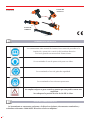
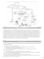
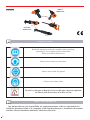
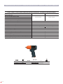
MANUAL DE INSTRUCCIONES
OPERATING INSTRUCTIONS
HERRAMIENTA NEUMÁTICA
PNEUMATIC TOOLS
COD. 55835
COD. 55836
COD. 55839
LLAVES DE IMPACTO
IMPACT WRENCHES
LLAVES DE CARRACA
RATCHET WRENCHES
ESPAÑOL................................ 2
ENGLISH................................. 8
ESPECIFICACIONES TÉCNICAS
TECHNICAL SPECIFICATIONS...14
GARANTIA/GUARANTEE......25
COD. 55840
COD. 55841
COD. 55837
COD. 55838
COD. 55844
LLAVES DE
IMPACTO
ESPAÑOL
LLAVES DE
CARRACA
HERRAMIENTA NEUMÁTICA
Lea atentamente éste manual de instrucciones antes de proceder a la
instalación, operación o servicio del producto descrito.
Por favor guarde este manual de instrucciones.
Se recomienda el uso de protección para sus oídos.
Se recomienda el uso de gafas de seguridad.
Se recomienda el uso máscara protectora.
No emplee oxigeno o gases reactivos puesto que esto podría causar una
explosión.
No sobrepase la presión de aire de 90 PSI/ 6.2 bar.
LLAVE DE CARRACA/IMPACTO
La herramienta se encuentra conforme a la directiva siguiente, documentos nominativos y
estándares relevantes: 2006/42/EC Directiva relativa a máquinas.
2
INSTRUCCIONES DE SEGURIDAD:
• Antes de usar esta herramienta, todos los operarios tienen que estar cualificados para su uso
y estar al tanto de las instrucciones de seguridad.
• No exceda la presión máxima de trabajo de 90 PSI/6.2 bar.
• Emplee un equipamiento de seguridad personal.
• Emplee aire comprimido en condiciones recomendables.
• Si la máquina presenta algún defecto de funcionamiento, retírelo de su uso inmediatamente
y solicite un servicio de mantenimiento y reparación.
• Si se usa la máquina con un contrapeso o con un dispositivo de soporte asegúrese de que
está fijado firmemente acoplado.
• Mantenga siempre las manos alejadas del accesorio de trabajo acoplado a la herramienta.
• La herramienta no está eléctricamente aislada. No usar nunca la herramienta si existe alguna
posibilidad de que ésta entre en contacto con electricidad.
• Cuando este empleando la máquina, adopte un apoyo o una posición firme y amarre
firmemente la herramienta para ser capaz de contrarrestar cualquier fuerza o reacción que podría
ser generada mientras emplee la herramienta.
• Emplee solo las partes de repuesto correctas. No improvise ni haga reparaciones
temporales.
• No bloquee con una cinta o con cuerda la válvula de apertura y cierre cuando esté en la
posición de funcionamiento. El gatillo/palanca etc, siempre deben poder volver a su posición de
apagado cuando se suelten.
• Siempre corte el suministro de aire de la herramienta y accione el gatillo/palanca etc, para
expulsar el aire de la manguera de alimentación antes de instalar, ajustar, o cambiar el accesorio de
trabajo
• Revise la manguera y los accesorios regularmente para ver si están desgastados.
Reemplácelo si fuera necesario. No tire de la herramienta mediante la manguera y asegúrese de
que sus manos están ajeadas del control de parada/puesta en marcha cuando este llevando la
herramienta con el suministro de aire conectado.
• Tenga cuidado de no engancharse con ropa, corbatas, pelo, trapos, etc. con las partes
móviles de la herramienta. Esto podría causar que su cuerpo fuese arrastrado hacia la máquina y
puede ser peligroso.
• No instale la herramienta a menos que se incorpore en el suministro de aire una válvula de
parada/puesta en marcha accesible y que opere de manera simple.
• Tenga cuidado de que el aire de escape de la máquina no cause ningún problema o golpe a
otra persona.
• No deje nunca la herramienta a menos que el accesorio de trabajo haya parado de
moverse.
• Asegúrese siempre de que el selector de reversibilidad está en la posición seleccionada
antes de accionar la herramienta.
• No emplee llaves de vaso excesivamente desgastadas en el cuadrado conductor.
• Revise periódicamente el cuadrado de la llave de impacto.
• Asegúrese de que la llave de vaso o extensión está firmemente fijada a la herramienta.
• Cuando este aflojando los tornillos, asegúrese primero de que hay distancia de seguridad
detrás de la herramienta para evitar que la mano se quede atrapada. La herramienta se desplazará
de la junta roscada cuando la tuerca o el tornillo se esté aflojando y se acercará a la rosca durante
el avance.
• Se espera que los usuarios adopten una práctica segura de la máquina, y observen cualquier
requerimiento legal relevante cuando este instalando o utilizando la máquina.
3
USO APROPIADO DE LA MÁQUINA
• La herramienta está diseñada para ser empleada con el propósito de guiar, apretar y aflojar
varillas roscadas, generalmente tornillos y tuercas cuando se encajan con un vaso conductor
apropiado.
• Está permitido emplear extensiones, articulaciones universales y adaptadores de vasos entre
cuadrado conductor de la llave de impacto y el cuadrado hembra de la llave de vaso.
• No emplee la herramienta para ningún otro propósito que no sea el especificado sin
consultar con el fabricante.
• No use nunca la herramienta como un martillo para desplazar o enderezar tornillos
roscados que estén torcidos.
• Nunca intente modificar la herramienta para otros usos.
Posición de trabajo
La herramienta debería emplearse como una herramienta de mano. Siempre es recomendable
que la herramienta se emplee cuando este situada en suelo firme. Puede ser empleada en otras
posiciones pero antes de cualquier uso, el operador debe colocarse en una posición segura
empleando una posición y agarre firmes y ser totalmente consciente de que cuando este aflojando
los tornillos, la herramienta puede moverse rápidamente lejos del remache sin terminar de
desenroscar. Hay que dejar siempre un margen de seguridad para evitar la posibilidad de que
cualquier mano/brazo/cuerpo quede atrapado durante este movimiento de retroceso.
4
POSICIONES DE AJUSTE EN SENTIDO DE APRIETE
3 2
Posiciones
Par
de ajuste
máximo
en sentido
de apriete
de apriete
1
Par
máximo
en la
primera
posición
Par
máximo
en la
segunda
posición
Par
máximo
en la
tercera
posición
Par
máximo
en la
cuarta
posición
CÓD.
ARTÍCULO
55835
LLAVE DE
IMPACTO
3/8”
610
3
182Nm
354 Nm
451 Nm
-
55836
LLAVE DE
IMPACTO
1/2”
680
3
182 Nm
354 Nm
501 Nm
-
55837
LLAVE DE
IMPACTO
3/4”
1695
4
812 Nm
1110 Nm
1465 Nm
1561 Nm
LLAVE DE
IMPACTO 1”
3900
3
2918 Nm
3295 Nm
3362 Nm
-
30
-
-
-
-
-
68
-
-
-
-
-
68
-
-
-
-
-
55838
55844
55839
55840
55841
LLAVE DE
CARRACA
NEUMATICA
1/4”
LLAVE DE
CARRACA
NEUMATICA
3/8”
LLAVE DE
CARRACA
NEUMATICA
1/2”
Las llaves de impacto no son herramientas de apriete controlado. Los pares alcanzados dependen
de muchos aspectos por lo que son aproximados.
5
OPERACIÓN INICIAL
Primero, asegúrese de que la herramienta está ajustada al vaso o accesorio requerido para llevar
a cabo la operación. Asegúrese de que la pestaña de cambio de sentido de reversibilidad está en la
posición correcta para apretar o aflojar el tornillo. Cuando la herramienta se detiene, el mango de
la herramienta se pude usar como la palanca de carraca para dar el apriete requerido a la unión. Se
pude aflojar la unión invirtiendo el sentido de la pestaña.
SUMINISTRO DE AIRE
Se debe emplear un aire limpio y lubricado con una presión de 90 PSI con el gatillo totalmente
pulsado.
Emplee una manguera de tamaño y longitud apropiados. Es recomendable que la herramienta
esté conectada al suministro de aire como se muestra en la figura A. No conecte la herramienta al
sistema de aire sin incorporar una válvula de acoplamiento. Para mantener el suministro limpio y
el aire lubricado a la presión correcta de la máquina, se recomienda emplear un filtro-reguladorlubricante en línea (FRL), como se muestre en la figura A. Para obtener más detalles del FRL solicite
la información a su proveedor. En caso de no emplear dicho equipo, la herramienta debería
lubricarse cortando el suministro de aire, eliminando la presión de la línea presionando el gatillo. A
continuación desconecte la línea de aire e introduzca en la entrada del reductor un poco (5 ml) de
un aceite lubricante de motor neumático adecuado, preferiblemente incorporando un inhibidor de
oxido. Vuelva a conectar la herramienta al suministro de aire y accione lentamente la herramienta
durante unos segundos para permitir la circulación de aceite. Si la herramienta se usa de manera
frecuente, o empieza a perder potencia e ir más lenta, lubríquela diariamente.
REGLAS DE SEGURIDAD PARA HERRAMIENTA DE AIRE
1) Inspeccione la manguera de aire para ver posibles grietas u otros problemas. Reemplace la
manguera si estuviera gastada.
2) Nunca apunte a otra persona con una manguera de aire.
3) Desconecte la herramienta cuando no esté usándola, o antes de llevar a cabo el servicio o
cambiar los accesorios.
4) Emplee mangueras y accesorios apropiados. No use nunca acoplamientos de cambio
rápido acoplados a la herramienta. En lugar de eso, coloque la manguera y el acoplamiento entre
la herramienta y el suplemento de aire. La conexión recomendable se muestra en la figura A. Las
herramientas neumáticas operan en un amplio rango de presiones de aire. Para una eficiencia
máxima y una vida de la herramienta mayor, la presión del aire suministrada a estas herramientas
no deberían exceder el índice en PSI en la herramienta cuando está operando. Empleando un
índice de presión mayor podría acelerar su desgaste y acortaría de manera drástica la vida útil
de la herramienta. También una presión de aire alta no es recomendable . El diámetro interno de
la manguera debería incrementarse para compensar mangueras inusuales de tamaño mayor (por
encima de 25 pies). El diámetro mínimo de la manguera debería ser de 3/8” I.D. y los accesorios
deberían tener las mismas dimensiones interiores. Es recomendable el uso de lubricadores de líneas
de aire y filtros de líneas de aire para prevenir agua en la línea que puede dañar la herramienta.
Drene el tanque de aire a diario. Limpie la rejilla de la entrada del filtro de aire al menos
semanalmente para retirar la suciedad acumulada o cualquier otra cosa que pudiera restringir el
flujo de aire.
6
SERVICIO DE MANTENIMIENTO
Es extremadamente recomendable adoptar y dirigir un programa de servicio regular para todas
las herramientas de potencia. Con un mantenimiento regular, se asegura un ciclo de vida mayor,
una potencia óptima y se reducen los gastos de operación. Las reparaciones de las herramientas
de aire tienen que llevarse a cabo por especialistas cualificados y por establecimientos de servicio
autorizados. Por esta razón, insistimos que no es recomendable llevar a cabo reparaciones si se
carece de los conocimientos necesarios. Vierta una cantidad abundante de aceite para herramientas
neumáticas en la entrada de aire. Si la herramienta continúa atascada, debe ser atendido por un
centro de servicios autorizado. Si la operación no puede restablecerse, la herramienta debería ser
revisada por el fabricante o por un centro de servicios autorizado.
GARANTÍA LIMITADA
Las herramientas neumáticas tienen garantía de un año desde su adquisición en caso de defectos
de material y calidad.
La garantía no cubre los siguientes casos:
1) Partes que se desgastan normalmente como rodamientos, alabes del rotor, etc.
2) Consumibles como papeles de lija, filtros, etc.
3) Usos incorrectos, descuido en el mantenimiento de la máquina o la herramienta,
modificación en la máquina.
4) Falta de lubricación o oxidación evidente, corrosión o suciedad
5) Herramientas/ máquinas usadas después de haber de estar en mal estado como empleando
una carraca con una abrazadera desgastada.
6) Que los usuarios no obedezcan los requisitos de nuestro manual.
Emplee solo partes autorizadas. Cualquier daño o mala función causada por el uso de partes no
autorizadas no será cubierto por la garantía.
7
IMPACT
WRENCHES
ENGLISH
RATCHET
WRENCHES
PNEUMATIC TOOLS
Read this instruction manual carefully before installing,
operating or servicing the product described.
Please save these instructions.
Always wear safety ear protection.
Always wear safety eye guard.
Always wear safety mask.
Do Not Use Oxygen or Reactive Gases as this may causes an explosion.
Do Not Exceed Air Pressure of 90 PSI/ 6.2 bar.
IMPACT / RATCHET WRENCH
We declaire that our sole responsibility for supply/manufacture of this air operated tool, to
which this document relates is in conformity of the following Directives, Nominative Documents
and their relevant Standards: 2006/42/EC Machinery Directive.
8
SECURITY INSTRUCTIONS:
• Before using this tool, all operators must be fully trained in its use and be aware of these
safety rules.
• Do not exceed the maximum working air pressure of 90 PSI/6.2 bar .
• Use personal safety equipment.
• Use only compressed air at the recommended conditions.
• If the tool appears to malfunction remove from use immediately and arrange for service and
repair If the tool is used with a balancer or other support device ensure that it is securely fixed.
• Always keep hands away from the working attachment fitted to the tool.
• The tool is not electrically insulated. Never use the tool if there is any chance of it coming
into contact with live electricity.
• When using the tool always adopt a firm footing and/ or position and grip the tool firmly to
be able to counteract any forces or reaction forces that may be generated whilst using the tool.
• Use only correct spare parts. Do not improvise or make temporary repairs.
• Do not lock tape, wire, etc. the on/off valve in the run position. The trigger/lever etc. must
always be free to return to the ‘off’ position when it is released.
• Always shut off the air supply to the tool, and depress the trigger/lever etc. to exhaust air
from the feed hose before fitting, adjusting or removing the working attachment.
• Check hose and fittings regularly for wear. Replace if necessary. Do not carry the tool by its
hose and always ensure the hand is well away from the on/ off control when carrying the tool with
the air supply connected.
• Take care against entanglement of moving parts of the tool with clothing, ties, hair, cleaning
rags, etc. This will cause the body to be drawn towards the tool and can be very dangerous.
• Do not install the tool unless an easily accessible and easily operable on/ off valve is
incorporated in the air supply.
• Take care that the tool exhaust air does not cause a problem or blows on another person.
• Never lay a tool down unless the working attachment has stopped moving.
• Always ensure that the reverse button is in the selected position before starting the tool.
• Do not use sockets with excessive wear to the input and output drives.
• Periodically check the square drive on the impact wrench.
• Make sure the socket, extension is firmly fixed to the tool.
• When loosening fasteners first ensure that there is sufficient clearance behind the tool
to avoid hand entrapment. The tool will move away from the threaded joint as the nut/bolt is
loosened and rides up in the thread moving the tool with it.
• It is expected that users will adopt safe working practices and observe all relevant legal
requirements when installing, using or maintaining the tool.
PROPER USE OF THE TOOL
• The tool is designed to be used only for the purpose of driving, tightening and loosening of
threaded fasteners, usually nuts and bolts, when fitted with a suitable drive socket.
• It is allowed to use impact-rated extension bars, universal joints and socket adapters
between the square output drive of the ratchet wrench and the female square drive of the socket.
• Do not use the tool for any other purpose than that specified without consulting the
manufacturer or the manufacturer’s authorized supplier as this may be dangerous.
• Never use the tool as a hammer to dislodge or straighten cross threaded fasteners.
• Never attempt to modify the tool for other uses.
9
POSICIPOSITIONS OF TIGHTENING TORQUE SETTING
3 2
Positions
of
tightening
torque
setting
Max.
torque in
the first
position
Max.
torque
in the
second
position
Max.
torque in
the third
position
Max.
torque in
the fourth
position
CODE
ITEM
Max.
torque
(Nm)
55835
PNEUNATIC
WRENCH 3/8”
610
3
182Nm
354 Nm
451 Nm
-
55836
PNEUNATIC
WRENCH 1/2”
680
3
182 Nm
354 Nm
501 Nm
-
55837
PNEUNATIC
WRENCH 3/4”
1695
4
812 Nm
1110 Nm
1465 Nm
1561 Nm
55838
PNEUNATIC
WRENCH 1”
3900
3
2918 Nm
3295 Nm
3362 Nm
-
30
-
-
-
-
-
68
-
-
-
-
-
68
-
-
-
-
-
55839
55840
55841
10
1
PNEUNATIC
RATCHET
WRENCH
1/4”
PNEUNATIC
RATCHET
WRENCH 3/8”
PNEUNATIC
RATCHET
WRENCH 1/2”
Impact wrenches are not controlled tightening tools. The values obtained depend on so many
aspects and that is why they are only approximate.
WORK STATIONS
The tool should only be used as a handheld hand operated tool. It is always recommended
that the tool is used when standing on the solid floor. It can be used in other positions but before
any such use, the operator must be in a secure position having a firm grip and footing and be
fully aware that when loosening fasteners the tool can move quite quickly away from the fastener
being undone. An allowance must always be made for this backward movement so as to avoid the
possibility of any hand/arm/ body entrapment.
INITIAL OPERATION
Fit securely to the tool the socket or attachment required to perform the operation. Ensure that
the reverse button situated on the opposite side to the square drive output shaft is in the correct
position for tightening or loosening the fastener. The nut/ bolt can then run down the thread using
the power drive of the tool. When the tool stops the handle of the tool can be used as a ratchet
lever and operated to give the required tightness of the joint. For loosening a joint the tool can be
used in the reverse sequence.
AIR SUPPLY
Use a clean lubricated air supply that will give a measured air pressure at the tool of 90 PSI with
the trigger fully depressed.
Use recommended hose size and length. It is recommended that the tool is connected to the air
supply as shown in figure A.
Do not connect the tool to the air line system without incorporating an easy to reach and
operated shut off valve.
It is strongly recommended that an air filter, regulator, lubricator (FRL) is used as shown in figure
A as this will supply clean,
lubricated air at the correct pressure to the tool. Details of such equipment can be obtained from
your supplier. If such equipment is not
used then the tool should be lubricated by shutting off the air supply to the tool, depressurising
the line by pressing the trigger on the tool.
Disconnect the air line and pour into the intake bushing a teaspoon (5 ml) of a suitable
pneumatic motor lubricating oil preferably
incorporating a rust inhibitor. Reconnect tool to air supply and run tool slowly for a few seconds
to allow air to circulate the oil.
If tool is used frequently lubricate on daily basis and if tool starts to slow or lose power.
SAFETY RULES FOR AIR TOOLS
1) Inspect the air hose for cracks or other problems. Replace the hose if worn.
2) Never point an air hose at another person.
3) Disconnect the tool when not in use, or before performing service or changing accessories.
4) Use proper hoses and fittings. Never use quick-change couplings attached at the tool. Instead,
add a hose and coupling between the tool and the air supply. The recommended hook-up is shown
in figure A. Pneumatic tools operate on a wide range of air pressures. For maximum efficiency and
11
longer tool life, the pressure of the air supplied to these tools should not exceed the rated PSI at the
tool when the tool is running.
Using a higher than rated pressure will cause faster wear and drastically shorten the tool’s life.
A higher air pressure can also cause an unsafe condition. The inside diameter of the hose should
be increased to compensate for unusually long air hoses (over 25 feet). Minimum hose diameter
should be 3/8” I.D. and fittings should have the same inside dimensions. The use of air line
lubricators and air line filters is recommended to prevent water in the line that can damage the tool.
Drain the air tank daily. Clean the air inlet filter screen on at least a weekly schedule to remove
accumulated dirt or other matter that can restrict air flow.
SERVICE AND MAINTENANCE
It is strongly recommended that a regular service programme for all air powered tooling be
adopted and managed, as reqularly maintained air tools ensure a long life cycle, optimal power and
reduced operating expenses. Repairs of air tools should be carried out by trained specialists and
authorized service dealers. For this reason, we strictly advise against attempting to repair without
this support. Pour a liberal amount of air tool oil in air inlet. If tool remains jammed, it should be
serviced by an authorized service Center. If operation cannot be restored, tool should be checked
by the fabricant or an authorized service center.
12
LIMITED WARRANTY
Air Tool Products (“the Products”) of the fabricant are warranted to be free from defects in
material and workmanship for one year from the date of purchase.
The warranty shall not apply to the following cases:
1) Normally wearable parts such as bearings, rotor blades, etc.
2) Consumables such as sanding pads, filters, etc. 3) Misuse, neglect in maintaining tool / machine or tool / machine modification. 4) Lack of lubrication or evidence of rust, dirt or corrosion. 5) Tools / Machines being used after they are badly worn such as using ratchet with worn yoke.
6) The users do not comply with our manual. Use only authorized parts. Any damage or
malfunction caused by the use of unauthorized parts is not covered by Warranty.
13
ESPECIFICACIONES TÉCNICAS / TECHNICAL SPECIFICATIONS - DESPIECE / SPARE PARTS DRAWING
COD. 55835 / COD. 55836 ESPECIFICACIONES TÉCNICAS / TECHNICAL SPECIFICATIONS
Cod. 55835
Cod. 55836
610 Nm / 450 ft-lb
680 Nm / 500 ft-lb
Max. Par / Max. torque
Max. Par ajuste / Max. Tightening torque
Par recomendado / Recommended torque
Perdida max. de par / Max. Loosening torque
Consumo medio de aire / Air consumption
120 l/min
Entrada de aire / Air inlet
1/4"
Nivel de presión sonoro / Noise pressure level
89,5 dbA
Nivel de potencia sonora / Noise power level
100,5 dbA
Vibración / Vibration
5,43 m/s2
5,2 m/s2
Presión de trabajo / Working pressure
6,3 bar / 90 PSI
Ø int (mm)
3/8"
Estructura de composite / Composite housing
Mecanismo de golpeo doble martillos / Twin hammer mechanism
Salida del aire por el mango / handle air exhaust
2 Posiciones de ajuste en sentido de apriete / 2 Tightening torque settings
Modelo ultraligero / Light weight model
R.P.M
14
55835
3/8"
55836
1/2"
11000
Nm/ ft-lb
610 Nm /450 ft-lb
680 Nm /500 ft-lb
L
160 mm
1,3
COD. 55835 DESPIECE / SPARE PARTS DRAWING
15
COD. 55836 DESPIECE / SPARE PARTS DRAWING
16
COD. 55837 ESPECIFICACIONES TÉCNICAS / TECHNICAL SPECIFICATIONS
1695 Nm / 1248 ft-lb
Max. Par / Max. torque
Max. Par ajuste / Max. Tightening torque
1560 Nm / 1150 ft-lb
Par recomendado / Recommended torque
270-1290 Nm / 200-950 ft-lb
Perdida max. de par / Max. Loosening torque
1628 Nm/ 1200 ft-lb
Consumo medio de aire / Air consumption
170 l/min
Entrada de aire / Air inlet
3/8"
Nivel de presión sonoro / Noise pressure level
90,8 dbA
Nivel de potencia sonora / Noise power level
101,8 dbA
Vibración / Vibration
5,3 m/s2
Presión de trabajo / Working pressure
6,3 bar / 90 PSI
Ø int (mm)
3/8"
Mecanismo de golpeo doble martillos / Twin hammer mechanism
Salida del aire por el mango / Handle air exhaust 3 Posiciones de ajuste en sentido de apriete / 3 Tightening torque settings
Posición de retroceso / Reverse position
55837
3/4"
R.P.M
Nm/ ft-lb
4000
1695 Nm/1248 ft-lb
L
248 mm
5,8
COD. 55837 DESPIECE / SPARE PARTS DRAWING
17
COD. 55838 ESPECIFICACIONES TÉCNICAS / TECHNICAL SPECIFICATIONS
Max. Par / Max. torque
2500 Nm / 1800 ft-lb
Max. Par ajuste / Max. Tightening torque
2388 Nm / 1760 ft-lb
Par recomendado / Recommended torque
500-1500 Nm / 680-2035 ft-lb
Perdida max. de par / Max. Loosening torque
2440 Nm / 1800 ft-lb
Consumo medio de aire / Air consumption
182 l/min
Entrada de aire / Air inlet
1/2"
Nivel de presión sonoro / Noise pressure level
98 dbA
Nivel de potencia sonora / Noise power level
109 dbA
Vibración / Vibration
6,9 m/s2
Presión de trabajo / Working pressure
6,3 bar / 90 PSI
Ø int (mm)
1/2"
Mecanismo de golpeo doble martillos / Twin hammer mechanism
3 Posiciones de ajuste en sentido de apriete / 3 Tightening torque settings
3 Posiciones de retroceso / 3 Reverse positions
Eje extendido 8" / 8" extended anvil
R.P.M
55838
18
1"
4000
Nm/ ft-lb
L
2500 Nm /1800 ft-lb
537 mm
10,6
COD. 55838 DESPIECE / SPARE PARTS DRAWING
19
COD. 55839 ESPECIFICACIONES TÉCNICAS / TECHNICAL SPECIFICATIONS
Max. Par / Max. torque
Par recomendado / Recommended torque
30 Nm / 22 ft-lb
Perdida max. de par / Max. Loosening torque
Consumo medio de aire / Air consumption
110 l/min
Entrada de aire / Air inlet
1/4"
Nivel de presión sonoro / Noise pressure level
85,5 dbA
Nivel de potencia sonora / Noise power level
96,5 dbA
Vibración / Vibration
7,33 m/s2
Presión de trabajo / Working pressure
6,3 bar / 90 PSI
Ø int (mm)
3/8"
Reversible / Reversible
Salida del aire por el mango / Handle air exhaust
Reducido tamaño para lugares de difícil acceso / Small size for inaccessible places
R.P.M
55839
1/4"
300
Nm/ ft-lb
30 Nm / 22 ft-lb
L
125 mm
COD. 55839 DESPIECE / SPARE PARTS DRAWING
20
0,47
COD. 55840/ COD. 55841 ESPECIFICACIONES TÉCNICAS / TECHNICAL SPECIFICATIONS
Cod. 55840
Cod. 55841
Max. Par / Max. torque
Par recomendado / Recommended torque
68 Nm / 50 ft-lb
Perdida max. de par / Max. Loosening torque
80 l/min
Consumo medio de aire / Air consumption
Entrada de aire / Air inlet
1/4"
Nivel de presión sonoro / Noise pressure level
82,8 dbA
93,8 dbA
Nivel de potencia sonora / Noise power level
Vibración / Vibration /
2,62 m/s
2,77 m/s2
2
Presión de trabajo / Working pressure
6,3 bar / 90 PSI
Ø int (mm)
3/8"
Reversible / Reversible
Salida del aire por el mango / Handle air exhaust
Mango de poliuretano / Polyurethane handle
55840
3/8"
55841
1/2"
R.P.M
Nm/ ft-lb
175
68 Nm / 50 ft-lb
L
265 mm
1,2
21
COD. 55840 DESPIECE / SPARE PARTS DRAWING
22
COD. 55841 DESPIECE / SPARE PARTS DRAWING
23
24
CERTIFICADO DE GARANTIA
GUARANTEE CERTIFICATE
CERTIFICAT DE GARANTIE
ARTICULO / ITEM / ARTICLE:.....................................................................................................................
Nº DE SERIE / SERIE Nº / Nº SERIE:............................................................................................................
DISTRIBUIDOR / DISTRIBUTOR / DISTRIBUTEUR:....................................................................................
PAIS / COUNTRY / PAYS:..............................................................................TEL.:....................................
FECHA DE VENTA / SALE DATE / DATE VENTE:.........................................................................................
NOMBRE DEL COMPRADOR / BUYER NAME / NOM DE L’ACHETEUR:...................................................
TEL. COMPRADOR / BUYER TEL. / TEL. DE L’ACHETEUR:.........................................................................
EGA MASTER GARANTIZA AL COMPRADOR DE ESTA MAQUINA LA GARANTIA TOTAL (DURANTE 12 MESES), DE LAS PIEZAS CON DEFECTOS DE FABRICACION. ESTA
GARANTIA NO CUBRE AQUELLAS PIEZAS QUE POR SU USO NORMAL TIENEN UN DESGASTE. PARA OBTENER LA VALIDEZ DE LA GARANTIA , ES ABSOLUTAMENTE
IMPRESCINDIBLE QUE COMPLETE Y REMITA ESTE DOCUMENTO A EGA MASTER , DENTRO DE LOS SIETE DIAS A PARTIR DE LA FECHA DE COMPRA.
EGA MASTER GUARANTEES TO THE BUYER OF THIS MACHINE THE TOTAL WARRANTY (DURING 12 MONTHS), OF THE PIECES WITH MANUFACTURING FAULTS.
THIS GUARANTEE DOES NOT COVER THOSE PIECES WORN OUT DUE TO A NORMAL USE. IN ORDER TO OBTAIN THE VALIDITY OF THIS WARRANTY , IT IS
ABSOLUTELY NECESSARY TO FULFILL THIS DOCUMENT AND RESEND IT TO EGA MASTER WITHIN 7 DAYS FROM SALE DATE.
EGA MASTER GARANTIE A L’ACHETEUR DE CETTE MACHINE LA GARANTIE TOTALE (PENDANT 12 MOIS) DES PIECES AVEC DEFAUTS DE FABRICATION. CETTE GARANTIE
NE COUVRE PAS LES PIECES QUE PAR UN USAGE NORMAL, SOIENT DETERIOREES. POUR OBTENIR LA VALIDITE DE LA GARANTIE, IL EST ABSOLUMENT IMPERATIF
COMPLETER ET ENVOYER CE DOCUMENT EGA MASTER, DANS UN DELAI DE 7 JOURS A PARTIR DE LA DATE D’ACHAT.
SELLO / STAMP / CACHET
EJEMPLAR PARA EGA MASTER / COPY FOR EGA MASTER / EXEMPLAIRE POUR EGA MASTER
CERTIFICADO DE GARANTIA
GUARANTEE CERTIFICATE
CERTIFICAT DE GARANTIE
ARTICULO / ITEM / ARTICLE:.....................................................................................................................
Nº DE SERIE / SERIE Nº / Nº SERIE:............................................................................................................
DISTRIBUIDOR / DISTRIBUTOR / DISTRIBUTEUR:....................................................................................
PAIS / COUNTRY / PAYS:..............................................................................TEL.:....................................
FECHA DE VENTA / SALE DATE / DATE VENTE:.........................................................................................
NOMBRE DEL COMPRADOR / BUYER NAME / NOM DE L’ACHETEUR:...................................................
TEL. COMPRADOR / BUYER TEL. / TEL. DE L’ACHETEUR:.........................................................................
EGA MASTER GARANTIZA AL COMPRADOR DE ESTA MAQUINA LA GARANTIA TOTAL (DURANTE 12 MESES), DE LAS PIEZAS CON DEFECTOS DE FABRICACION. ESTA
GARANTIA NO CUBRE AQUELLAS PIEZAS QUE POR SU USO NORMAL TIENEN UN DESGASTE. PARA OBTENER LA VALIDEZ DE LA GARANTIA , ES ABSOLUTAMENTE
IMPRESCINDIBLE QUE COMPLETE Y REMITA ESTE DOCUMENTO A EGA MASTER , DENTRO DE LOS SIETE DIAS A PARTIR DE LA FECHA DE COMPRA.
EGA MASTER GUARANTEES TO THE BUYER OF THIS MACHINE THE TOTAL WARRANTY (DURING 12 MONTHS), OF THE PIECES WITH MANUFACTURING FAULTS.
THIS GUARANTEE DOES NOT COVER THOSE PIECES WORN OUT DUE TO A NORMAL USE. IN ORDER TO OBTAIN THE VALIDITY OF THIS WARRANTY , IT IS
ABSOLUTELY NECESSARY TO FULFILL THIS DOCUMENT AND RESEND IT TO EGA MASTER WITHIN 7 DAYS FROM SALE DATE.
EGA MASTER GARANTIE A L’ACHETEUR DE CETTE MACHINE LA GARANTIE TOTALE (PENDANT 12 MOIS) DES PIECES AVEC DEFAUTS DE FABRICATION. CETTE GARANTIE
NE COUVRE PAS LES PIECES QUE PAR UN USAGE NORMAL, SOIENT DETERIOREES. POUR OBTENIR LA VALIDITE DE LA GARANTIE, IL EST ABSOLUMENT IMPERATIF
COMPLETER ET ENVOYER CE DOCUMENT EGA MASTER, DANS UN DELAI DE 7 JOURS A PARTIR DE LA DATE D’ACHAT.
SELLO / STAMP / CACHET
EJEMPLAR PARA EL CLIENTE / COPY FOR THE CUSTOMER / EXEMPLAIRE POUR LE CLIENT
C/ ZORROLLETA 11, POL. IND. JUNDIZ
01015 VITORIA, SPAIN P.O.B. APTDO. 5005
TEL. 34 - 945 290 001 FAX. 34 - 945 290 141
[email protected]
www.egamaster.com