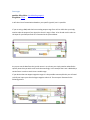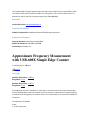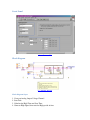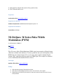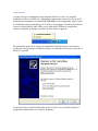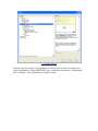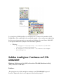
1
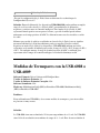
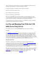
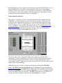
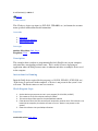
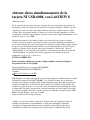
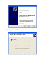
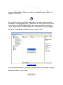
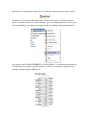
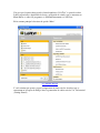
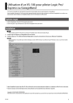
Cambiando entre NI-DAQmx y NIDAQmx Base para las Tarjetas USB-6008,
USB 6009 y 6501
Hardware: Multifunction DAQ (MIO)>>Portable>>USB-6008
Problema: Tengo una Tarjeta USB-6008 y quiero cambiar entre utilizar NI-DAQmx y NIDAQmx Base. ¿Cómo puedo hacer esto?
Solución:
Estas instrucciones solo aplican para dispositivos USB-6008, USB-6009 and USB-6501.
Cambiando a NI-DAQmx Base
1.
Abrir el administrador de Dispositivos de Windows (Windows Device Manager).
a. Dar clic derecho sobre My Computer y seleccionar Propiedades
b. Selecciona la pestaña de Hardware y da clic en Device Manager
2.
Busca el dispositivo USB 6008 (6009 o 6501) bajo la categoría de Dispositivos de
Adquisición de Datos
3. Dar clic derecho sobre el dispositivo y selecciona Actualizar Driver (Update
Driver)
4. En la ventana que se abre seleccionar instalar desde una localidad especifica y
aprieta siguiente.
5. En la siguiente ventana selecciona que no busque el driver , que se selecciona
manualmente (Don't search. I will choose the driver to install). Y presione Next
6. Seleccione NI USB-6008 Multifunction IO y presione Next
7. Esto prepara la tarjeta para que reciba el nuevo firmware. El dispositivo aparecerá
ahora bajo NI-VISA USB Devices. Si no aparece o aparece con un signo amarillo
de exclamación, desconecta el cable usb y vuélvelo a conectar esto debe de
colocarlo en la categoría correcta.
8. Corre el programa Firmware Switcher que se incluye como anexo.
9. Debes de ver una entrada para el USB-6008 que colocaste para recibir el firmware.
Para cambiar el dispositivo a NI-DAQmx Base, Selecciona “Switch to NI-DAQmx
Base”
10. Ya que seleccionaste esto presiona el botón Updatedate
11. Cierra la aplicación y abre el “NI-DAQmx Base List Devices utility” (Start >>
Programs >> National Instruments >> NI-DAQmx Base >> Utilities)
y deberías de ver aquí tu tarjeta 6008
Cambiando a NI-DAQmx
1.
Abrir el administrador de Dispositivos de Windows (Windows Device Manager).
a. Dar clic derecho sobre My Computer y selecciona Propiedades
b. Selecciona la Tab de Hardware y da clic en Device Manager
2.
Busca el dispositivo USB 6008 (6009 o 6501) bajo la categoría de Dispositivos de
Adquisición de Datos
Dar clic derecho sobre el dispositivo y selecciona Actualizar Driver (Update
Driver)
En la ventana que se abre seleccionar instalar desde una localidad especifica y
aprieta siguiente.
En la siguiente ventana selecciona que no busque el driver , que se selecciona
manualmente (Don't search. I will choose the driver to install). Y presione Next
Seleccione NI USB-6008 Multifunction IO y presione Next
Esto prepara la tarjeta para que reciba el nuevo firmware. Como DAQmx carga el
firmware en forma automática no es necesario usar otro programa. El dispositivo
aparecerá ahora bajo NI-VISA USB Devices. Si no aparece o aparece con un signo
amarillo de exclamación, desconecta el cable usb y vuélvelo a conectar esto debe de
colocarlo en la categoría correcta.
Abre Measurement and Automation Explorer y expande en Devices and Interfaces
Aquí deberías de ver un registro de la USB-6008
3.
4.
5.
6.
7.
8.
9.
Ligas Relacionadas:
Archivos Adjuntos:
- DriverSelector.exe
¿Por qué no Puedo Simular mi Dispositivo
en Measurement & Automation Explorer?
Hardware: Multifunction DAQ (MIO)>>Basic>>PCI-6014, Multifunction DAQ
(MIO)>>Basic>>PCI-6010, Multifunction DAQ (MIO)>>Basic>>DAQPad-6015 for USB,
Multifunction DAQ (MIO)>>Portable>>DAQPad-6015 for USB w/BNC Term,
Multifunction DAQ (MIO)>>Basic>>PCI-6013, Multifunction DAQ
(MIO)>>Basic>>DAQPad-6016 for USB w/Screw Term, Multifunction DAQ
(MIO)>>Basic>>DAQPad-6015 for USB w/Screw Term, Multifunction DAQ
(MIO)>>Portable>>DAQPad-6015 for USB w/Mass Term, Multifunction DAQ
(MIO)>>Basic>>DAQPad-6015 for USB, Multifunction DAQ (MIO)>>Portable>>USB6009, Multifunction DAQ (MIO)>>Portable>>DAQPad-6015 for USB w/BNC Term,
Multifunction DAQ (MIO)>>Portable>>USB-6008, SCXI>>Modules>>SCXI-1600
Problema: Mi dispositivo si es soportado por NI-DAQmx y lo tengo instalado en mi
computadora. Quiero simular mi dispositivo en Measurement & Automation Explorer
(MAX). Cuando voy a voy a My System » Data Neighborhood » Devices and Interfaces y
doy clic derecho en NI-DAQmx Devices y selecciono Create New NI-DAQmx Device... »
Simulated NI-DAQmx Device, mi dispositivo no aparece. ¿Cómo puedo simular mi
dispositivo?
Solución: Algunos dispositivos de NI-DAQmx no pueden ser simulados. Aquí está la lista:
•
•
•
•
•
•
•
•
•
•
PCI-6010
PCI-6013
PCI-6014
USB-6008
USB-6009
USB-6501
USB-6525
DAQPad-6015
DAQPad-6016
SCXI-1600
También es importante considerar que Traditional NI-DAQ, no soporta dispositivos
simulados. En la mayoría de los casos puedes simular un dispositivo similar al que tenemos
pero hay que recordar que puede haber diferencias en las capacidades de los dispositivos
Ligas Relacionadas:
KnowledgeBase 3JLD2HB9: What are NI-DAQmx Simulated Devices and How Do I Use
Them?
Archivos Adjuntos:
¿Qué opciones de calibración hay
disponibles para dispositivos de bajo
precio de DAQ USB?
Hardware: Multifunction DAQ (MIO)>>Portable>>USB-6008, Multifunction DAQ
(MIO)>>Portable>>USB-6009
Problema:
Cuando presiono clic derecho en mi dispositivo de bajo precio de DAQ (USB-6008, USB-6009,
etc.), la opción de "Self-Calibrate" no está disponible.
Solución:
Dispositivos de bajo precio de DAQ USB no tienen la habilidad de hacer auto calibración o selfcalibrate. Además, no hay opción de obtener un certificado de calibración en estos dispositivos.
Si requiere un certificado o la opción de hacer auto-calibración, las opciones son comprar un
dispositivo DAQ de bajo precio (como el PCI-6221) o un dispositivo de alta calidad (como el USB
DAQPad- 6015). Estas alternativas también ofrecen muchos beneficios en funcionamiento
además de las opciones de calibración. Para una comparación detallada de dispositivos de
DAQ USB, favor de referirse a guía de selección de equipos USB para Adquisición de datos, que
se encuentra en la casilla inferior.
¿Por Qué Mis Tarjetas USB-6008/6009
Tienen Diferentes Resoluciones para
Mediciones en las Formas Diferencial y de
Single-Ended?
Hardware: PXI/CompactPCI>>Controllers
Problema:
El Manual de Usuario para el USB-6008 y USB-6009 dice que hay dos entradas diferentes
de resoluciones:
NI USB-6008
NI USB-6009
12 bits Diferencial
11 bits Single-Ended
14 bits Diferencial
13 bits Single-Ended
¿Por qué la configuración Single-Ended tiene un bit menos de resolución que la
configuración Diferencial?
Solución: En modo diferencial, los dispositivos USB-6008/6009 pueden utilizar un amplio
rango de su Convertidor Analógico-Digital (ADC) para mediciones de diferencias
negativas y positivas entre sus entradas analógicas. En el modo Single-Ended, el ADC
espera una entrada positiva con respecto a la tierra, y por ello la unidad puede utilizar
unicamente en el rango positivo del ADC. La diferencia entre estos dos modelos es un bit
de señal.
Mientras que este bit de señal no es utilizado en el modo Single-Ended, esto no significa
que una medición Single-Ended medición no puede ser negativa. Para leer voltajes
negativos en modo Single-Ended, los dispositivos USB-6008/6009 utilizan una red de
resistencias en la entrada del módulo para escalar el rango de -10 V a 10 V al rango de 0V a
+10 V . De cualquier manera, el rango de la mitad superior del ADC es utilizado para
representar todo el rango de la entrada análogica, la resolución disminuye un bit.
Medidas de Termopares con la USB-6008 o
USB-6009
Software Primario: Driver Software>>NI-DAQmx Base
Versión de Software Primario: 1.4
Versión de Software Primario Corregido: N/A
Software Secundario: N/A
Hardware: Multifunction DAQ (MIO)>>Portable>>USB-6008, Multifunction DAQ
(MIO)>>Portable>>USB-6009
Problema:
Estoy utilizando una USB-6008 y deseo tomar medidas de termopares, pero mis medidas
no parecen ser muy exactas.
Solución:
La USB-6008 tiene una resolución de 12-bit y un rango mínimo de +/-1 volt. La USB-6009
tiene 14-bit de resolución con un mínimo de rango de +/- 1 volt. Esto da una resolución de
480 y 122 microvolts, respectivamente. La respuesta estimada de los diferentes tipos de
termopares puede obtenerse de la tabla de termopares de NIST.
Los tipos más comunes de termopares tienen la siguiente respuesta:
Tipo K: 41 microVolts por grado Celsius
Tipo J: 56 microVolts por grado Celsius
Tipo T: 52 microVolts por grado Celsius
Por lo tanto la USB-6009 solo puede medir cambios de aproximadamente 2-3 grados
Celsius dependiendo del tipo de termopar que esté utilizando. La USB-6008 es peor (>9
grados Celsius de resolución) y no debe utilizarse para medidas de termopares.
Una mejor alternativa para medida de termopares es la USB-9211, ya que está diseñada
específicamente para tomar medidas de termopares.
Get Up and Running Fast With the USB
600x Series DAQ Device
Start all of the features of your USB 6008/6009 DAQ device right out of the box.
Overview
The USB-600x series DAQ devices are a fast and affordable way to acquire and control
real world signals with your computer. Despite its simplicity, it can still require time to
write and debug application specific programs, which you may find prohibitive. This is
especially true in environments where the application is constantly changing and evolving,
such as academic laboratories. The purpose of this Developers Zone article is to provide an
out-of-the-box solution for rapid deployment with the USB-600x series devices.
What Does this VI Do?
This VI uses a software loop to poll all inputs and update all outputs on the device
simultaneously. It allows you to switch analog inputs between Referenced Single Ended
mode (all pins referenced to the device ground) and Differential mode (voltage between
two different pins) on the fly. You can also toggle digital pins to be either input or output.
A count indicator shows the digital edges that are counted on pin PFI0.
This code comes in two library files containing the same code base. One is cross platform
(daqmxbaseversion.llb) and can be run on Windows, Linux or Mac OS X using the NIDAQmx Base driver suite. The other is for Windows PC computers only
(daqmxversion.llb) using the standard NI-DAQmx driver suite.
The NI-DAQmx version has slightly more functionality than the NI-DAQmx Base version.
The NI-DAQmx Base version runs at the maximum rate that it can on your machine,
utilizing as many system resources as your operating system allows it. The NI-DAQmx
version, however, gives you the ability to adjust the sample rate. Additionally, you can
disable pins that are not connected to increase performance.
Understanding the Interface
The interface is designed to be in the same arrangement as the pin configuration of the
USB-600x as seen from the picture in the center of the front panel. On the left are the
analog ports and on the right the digital ports. On the bottom of the front panel are the
program controls. There is a string control for you to enter the device ID of your USB
device. In Windows, the device ID can be found in the device list in Measurement and
Automation Explorer. On a Macintosh or Linux system, run the lsdaq utility program
located in the National Instruments application directory. The activity light blinks to
indicate the VI is running, and the Stop button stops the VI.
The analog inputs can be configured for Differential or Referenced Single Ended
measurements. You can switch between these two modes by clicking on the tab control
that contains the analog voltage indicators. Below the analog input indicators are the
analog output controls. Simply enter a number between 0V and 5V and that voltage will be
applied to the corresponding pins.
Each digital pin can be an input or output by choosing the corresponding Direction
control. The Drive control and the State indicator are Boolean data types describing the
digital (TTL) logic level. The State indicator displays the measured logic level on a digital
pin when the Direction is set to IN. When the Direction is set to OUT, the State indicator
displays the output logic level on the line. The Drive control allows you to manually set
the logic level that is outputted on the line when the Direction is set to OUT.
In the NI-DAQmx version, you will see a timing section in the bottom left corner. Use the
Max Rate control to set the desired sampling rate of the program. The Current Rate
indicator displays the rate at which that the device is actually being sampled. It is a moving
average so the displayed number can be read by the human eye. As such Current Rate
will appear to ramp up when the maximum rate is changed. The minimum rate is 0.33 Hz.
This is done because the program responds to user input once per iteration of the loop, and
very slow update rates can result in the interface becoming unresponsive for a very long
time. You can use lower rates if necessary by changing the property of the Max Rate
control’s Data Entry limits in its properties menu.
The maximum achievable rate is determined by the speed of your computer. You will
notice that eventually the Current Rate hits a ceiling, even though the Max Rate is set to
be higher. To remedy this, you can disable unused pins on the front panel. A ring control
above each of the different pin groups will allow you to select the operational mode of that
group. In particular, disabling one or more of the digital ports will drastically increase your
maximum attainable sample rate.
Downloads
daqmxversion.llb
daqmxbaseversion.llb
NI-DAQmx: Find DAQ Device Resource
Programmatically
0 calificación(es) | 0.00 de 5
Imprimir
Visión General
This VI takes a device type input (ex. PCI-6251, USB-6008, etc.) and returns the resource
name specified in Measurement and Automation
Contenido
1. Description
2. Instructions for Running
3. Block Diagram Steps
Descargas
nombre del archivo: find_daq.vi
Requisitos: View
Description
This example shows you how to programmatically find a DAQ device in your computer
and return the corresponding resource name. This is useful if you are deploying an
application where the DAQ resource name is unknown and there are multiple devices used
in the computer.
Instructions for Running
Input the DAQ device required for the program (ex. NI 9225, PCI-6251, SCXI-1520, etc.).
If the device is not located in the computer, a "Device is not present in the system" error
will occur. The Device names are not case sensitive.
Block Diagram Steps
1.
2.
3.
4.
Set the device type you want to use in your program (Ex. PCI-6251, NI 9225)
This creates an array of the devices name set in MAX
This returns the product type for the specified Device Name
If the device is found, the case structure will output the resource name. If the device is not
located in the computer, the device will return an error "Device is not present in the
system"
5. Place this reference into your DAQmx functions
Requisitos
nombre del archivo: find_daq.vi
Requisitos de Software
Software de Aplicación: LabVIEW Professional Development System 8.0
Idioma(s): LabVIEW
Requisitos de Hardware
Grupo de Hardware: CompactDAQ, Multifunction DAQ (MIO), Digital I/O (DIO), SCXI, Portable DAQ
Find NI-DAQmx Devices
Programmatically in LabVIEW
Visión General
The attached LLB file contains a polymorphic VI that demonstrates how to
programmatically find and select for a task an NI-DAQmx device installed in a system.
Descargas
nombre del archivo: daqmx_find_device.llb
Requisitos: View
This VI (daqmx_find_device.vi) allows for an installed DAQmx device to be found in one
of 3 different ways:
1. By Product Type - Examples of product types are PCI-6251, PCI-6040E, USB-6009, etc.
2. By Product Category - Examples of product categories are M Series, E Series, S Series,
etc.
3. By Product Serial Number
Joystick Inputs with DAQ Card Outputs.
Visión General
This example takes inputs from a joystick, scales the data and outputs to a DAQ device.
This input only takes the X-axis data but can be expanded to use X,Y, and Z axes.
Descargas
nombre del archivo: joysticktodaqoutput.vi
Requisitos: View
It will take a bit of customization based on your specific joystick, but it is possible.
If you are using a DAQ card that has an analog output range from -10V to +10V then you simply
need to scale the output of your joystick so that it's range is from -10 to 10 and use this value as
the input for your DAQmx read. As is illustrated in the picture below.
As you can see the data from the joystick comes in as a cluster you simply need to unbundle the
specific pieces that you wish to use and scale accordingly. In this example the X axis is divided by a
certain factor in order to scale it into a usable range.
If your device does not support negative ranges it is also possible to accomplish this you will need
to shift your input up so that the largest negative value is 0. The concept is illustrated in the
following picture.
this example adds the largest negative value that the joystick outputs (in this case 32768) in order
to make all values positive, and then divides by a scaling factor. This scales the data so that it is
between 0V and 5V, which is the output range of the USB-6008/6009.
Requisitos
nombre del archivo: joysticktodaqoutput.vi
Requisitos de Software
Software de Aplicación: LabVIEW Professional Development System 8.0
Requisitos de Hardware
Grupo de Hardware: Multifunction DAQ (MIO)
Modelo de Hardware: USB-6009, USB-6008
Controlador: NI-DAQmx 8.3
Approximate Frequency Measurement
with USB-600X Simple Edge Counter
2 calificación(es) | 4.00 de 5
Imprimir
Descargas
nombre del archivo: 1406.vi
Requisitos: View
nombre del archivo: 1405.vi
Requisitos: View
This application written in LabVIEW 7.1 shows how to use the simple event counter functionality
of the USB-600X devices and the computer's timer to calculate an approximate average frequency
measurement of the signal on the counter channel. This functionality is not inherently available for
the devices.
The operation is as follows:
Steps:
1. Create empty task
2. Create a Counter Input channel to Count Events. The Edge parameter must be set to increment
on falling edges.
3. Call the Start VI to arm the counter and begin counting. The counter will be preloaded with the
Initial Count.
4. The counter will be continually polled until the Stop button is pressed on the front panel. This
will give both counter readings as well as approximate frequency readings.
5. Stop the task
6. Call the Clear Task VI to clear the Task.
7. Use the popup dialog box to display an error if any.
Requisitos
nombre del archivo: 1406.vi
Requisitos de Software
Software de Aplicación: LabVIEW Base Development System 7.1
Idioma(s): LabVIEW
Requisitos de Hardware
Grupo de Hardware: Multifunction DAQ (MIO)
Modelo de Hardware: USB-6009, USB-6008
Controlador: NI-DAQmx 7.4
nombre del archivo: 1405.vi
Requisitos de Software
Software de Aplicación: LabVIEW Base Development System 7.1
Idioma(s): LabVIEW
Requisitos de Hardware
Grupo de Hardware: Multifunction DAQ (MIO)
Modelo de Hardware: USB-6008, USB-6009
Controlador: NI-DAQmx Base 1.4
Continuous Software Timed Analog
Output for the USB-6008 and USB-6009
10 calificación(es) | 3.60 de 5
Imprimir
Descargas
nombre del archivo: cont_ao_6008_6009.zip
Requisitos: View
This program demonstrates how to perform continuous analog output tasks on the USB-6008 /
6009 and also incorporates the theory of operation that is associated with software timed analog
output. Continuous software timed analog output means that your analog channel will update
only once for every iteration of the program's while loop. It is important to remember that these
devices allow a maximum update rate of 150 samples per second on each channel; therefore the
main program's while loop can iterate no faster than once every 6 ms.
It is also important to remember that these devices allow an output voltage range of 0 to 5 Volts.
For demonstration purposes, this program outputs a sine wave with a DC offset of 2.5V and allows
the user to select the number of points per cycle. It will be observed that increasing the points per
cycle will increase the resolution of the output waveform, but also decreases its frequency. The
approximate period of the output waveform is equal to the points per cycle times the output rate.
Requisitos
nombre del archivo: cont_ao_6008_6009.zip
Requisitos de Software
Software de Aplicación: LabVIEW Professional Development System 7.1, LabVIEW Base
Development System 7.1, LabVIEW Full Development System 7.1
Idioma(s): LabVIEW
Requisitos de Hardware
Grupo de Hardware: Multifunction DAQ (MIO)
Modelo de Hardware: USB-6009, USB-6008
Controlador: NI-DAQmx 8.0
obtener datos simultaneamente de la
tarjeta NI USB-6008, con LabVIEW 8
Muy buenos días!
En el desarrollo de una aplicación para el control de un servomecanismo de posición (de
laboratorio), realicé una rutina para la lectura de dos canales analógicos. Debido a que me
sugirieron en varias ocasiones que debía utilizar un solo task y asignarle los dos canales,
eso hice. Pero, no encontré manera de obtener esos datos de manera simultánea, es decir,
visualizarlos o utilzarlos para cualquier operación sin tener que elegirlo manualmente! (y de
manera de número entero DBL)
Encontré una manera de leer ambas señales con la ayuda del foro, ya que me sugirió
realizar la lectura de manera secuencial! Lo probé y al parecer funciona correctamente, o
por lo menos obtengo los valores que llegan a los canales que utilicé! Me preocupa el hecho
de que tuve que crear Global virtual channels con el mismo nombre de los canales que le
asigné a los canales físicos del task, puesto que al emplear el "Read Node " junto al
"DAQmx Read.vi" para indicarle cual canal leer: la constante que creaba en la propiedad
"ChannelsToRead" no aparecían los canales asignados en la creación de mi task
multicanal! (ver lector de 2 channels.vi)
ESTO ES CORRECTO?
Exite un método estándar que permita adquirir multiples entradas analógicas?
Me pueden enviar un VI ejemplo?
Estoy usando labview 8! y la tarjeta NI USB-6008!
MUCHAS GRACIAS DE ANTEMANO..
Adjuntos:
Lector de 2 channels.vi 128 KB
Hola Magduti, yo siempre obtengo dos o mas señales analogicas simultaneamente en modo
diferencial con una tarjeta DAQ USB-6008. Uso el DAQ Assistant, que se encuentra
en Funciones>>Express>>Input>>Daq Assitant. Primero agrego una señal de entrada por
ejemplo de temperatura, el asistente me guia al final de una ventana. Luego alli hay una
opcion de agregar otro canal , en este caso escojo nuevamente entrada analogica de voltaje
o temperatura, asi puedes agregar hasta 4 entradas analogicas de señal segun tu necesidad.
Te enviaria un grafico de lo que te explico pero en este momento no tengo la tarjeta USB6008 a la mano. Prueba y veras que es simple.
Espero te halla servido en algo mi ayuda.
Amigo, si es una sola medida es muy fácil. Aunque tienes que explicarte mejor! Un
medidor de temperatura es un termómetro! si tienes una termocupla o algun otro
transductor de temperatura entonces tengo entendido es mas dificil, porque debes
acondicionar la señal antes de poder leerla con una tarjeta de adquisición de datos.
Yo trabajé con la NI USB-6008, y para termocupla creo que hay que hacer un circuito para
amplificar esa señal antes de poder conectarla a la tarjeta de adquisición, porque está en el
orden de los milivoltios (mV).
Te mando una imagen de como se realiza fácil una adquisición de datos de una tares(task)
con varios canales asociados a ella.
Suerte! Si puedes explicarme mejor, a lo mejor te puedo ayudar correctamente.
Adjuntos:
figura de abajo
Las tarjetas 6008 no cuentan con ninguno de estos dos componentes. Aun así si
se puede hacer un PWM, pero se va a controlar por software, que para muchas
aplicaciones va a ser suficiente, solo va a estar un poco más limitado en velocidad
y precisión.
En los siguientes links hay ejemplos de cómo generar PWM en las salidas
analógicas y en la digital.
http://zone.ni.com/devzone/cda/epd/p/id/5235
http://zone.ni.com/devzone/cda/epd/p/id/5043
NI-DAQmx: Software-Timed Variable
Duty Cycle Pulse Train Using Analog
Output
NI-DAQmx: Software-Timed Variable
Duty Cycle Pulse Train Using Analog
Output
3 calificación(es) | 3.00 de 5
Imprimir
Visión General
This example illustrates how to use software timing to create a variable duty cycle pulse
using an analog output channel.
Contenido
1.
2.
3.
4.
Instructions for Running
I/O Connections
Front Panel
Block Diagram
Descargas
nombre del archivo: ao-var_duty_cycle.vi
Requisitos: View
Instructions for Running
1. Choose Physical Channel for analog output, and assign proper maximum and minimum
voltage output levels for the DAQ card.
2. Assign Duty Cycle Parameters. Make sure the number of pulses equals the size of the
'Percent Duty Cycle' array.
I/O Connections
Make sure your signal output terminal matches the Physical Channel I/O Control. For
further connection information, refer to your hardware reference manual.
Front Panel
[+] Ampliar Imagen
Block Diagram
[+] Ampliar Imagen
Block Diagram Steps:
1. Create an Analog Output Voltage Channel
2. Start Task
3. Calculate the High Time and Low Time
4. Generate High Signal, then wait for High period of time
5. Generation Low Signal, then wait for Low period of time
6. Clear Task and show errors
Requisitos
nombre del archivo: ao-var_duty_cycle.vi
Requisitos de Software
Software de Aplicación: LabVIEW Base Development System 7.1
Requisitos de Hardware
Controlador: NI-DAQmx
NI-DAQmx: M Series Pulse Width
Modulation (PWM)
2 calificación(es) | 5.00 de 5
Imprimir
Visión General
This VI creates a Pulse Width Modulation (PWM) signal on any number of Digital Output
(DO) lines available on the hardware. You may specify the duty cycle and frequency of the
PWM. Only one Counter Output (CO) is used as the sample clock for multiple Digital
Outputs (DO), rather than using one counter per PWM signal. This example was intended
for use with National Instruments' M Series devices.
Descargas
nombre del archivo: pwm_multdo.zip
Setup
1. Select the device name of the M Series device.
2. Select the correlated Digital I/O lines to use. On an M series, this is port0.
3. Expand the array of Duty Cycle Controls so that you have one control for each line you
have specified.
4. Make a connection to any of the digital lines on the selected port.
Notes
The Frequency value is the frequency of one complete square wave pulse. The sample
clock rate is actually 1000 * Frequency, and each complete square wave consists of 1000
points. Hence, the maximum frequency that can be achieved is dependent on the maximum
update rate of the hardware, calculated as follows:
MAX Frequency = MAX Digital Rate/1000
You can increase the maximum value of Frequency by editing the VI to create a square
wave array of size less than 1000.
Cómo usar la DAQ USB 6008 o 6009
recién adquirida
2 calificación(es) | 4.00 de 5
Imprimir
Visión General
Se describe la manera de configurar apropiadamente la tarjeta USB 6008/9 que usted ha
adquirido recientemente para leer señales o generarlas.
Hardware necesario
Tarjeta DAQ USB 6009 ó 6008
Cable de conexión USB
Computadora con al menos un puerto USB
Conecta las terminales de tornillo a las terminales de la DAQ y pegue las etiquetas
necesarias en la tarjeta. Encienda su computadora y permita que cargue su sistema
operativo.
Software necesario
LabView
NI – DAQmx
Programación
Asegurese de que la computadora tenga instalado LabView. Si no es así, instálelo
insertando los discos de LabView y siguiendo las instrucciones. Inserte los discos de NI
DAQ mx que acompañan a la tarjeta DAQ USB 6008/9 en la computadora. Siga los pasos
de instalación para los controladores de la tarjeta y del programa. Cuando haya finalizado,
conecte la tarjeta DAQ al cable USB y este a algún puerto USB de la computadora.
Aparecerá un globo de diálogo en la barra de tareas como el siguiente:
Posteriormente aparecerá el asistente de instalación de hardware nuevo. Seleccione la
opción que evita que busque en Windows Update el controlador de la tarjeta y presione el
botón de “siguiente”:
Luego aparecerá la ventana de ubicación de driver. En este caso seleccione instalar el
programa automáticamente y de click en “Siguiente”:
Aparecerá una venta indicando que la instalación se está llevando a cabo y luego
confirmará que la instalación ha sido éxitosa:
Comprobando la instalación adecuada de la DAQ USB 6008/9
Ejecute el programa Measurements and Automation Explorer (MAX) que se
encuentra en Menú Inicio >> Todos los programas >> National Instruments. El ícono del
programa es el siguiente:
Una vez abierto, revise en la sección de configuración y extienda la ramificación Devices
and Interfaces >> NI DAQ-mx Devices. Si la instalación fue exitosa, aparecerá un ícono en
verde de una tarjeta NI USB-6008/9 y MAX le abrá asignado un nombre a esta del tipo
“Dev#”. Tome en cuenta este nombre porque será el identificador de la tarjeta en cualquier
programa de National Instruments para acceder a ella. Presione el botón de “Self-Test” para
revisar que la comunicación es efectiva si aparece la ventana “Success”
[+] Ampliar Imagen
Como una breve introducción, la pestaña de Test Panels da acceso las terminales del equipo
de National Instruments conectadas a la computadora. Con esto se puede comprobar el
buen funcionamiento de cada terminal.
Reset Device es útil cuando la tarjeta deja de funcionar correctamente por varias razones.
Por último, al presionar click derecho sobre el ícono de la tarjeta, se abrirá un menú en
donde se pueden encontrar los “Device Pinouts” que es la configuración física de los pines
en la tarjeta DAQ y esto aplica para cualquier modelo de DAQ de National Instruments.
Por ejemplo, para la DAQ USB 6008/9 los “Device Pinouts” se encuentran acomodados de
tal manera que las entradas y salidas analógicas (AI/AO) se encuentran separadas de las
entradas y salidas digitales (DI/DO) así:
Una vez que el aparato haya pasado el auto diagnóstico “Self Test” se procede a abrir
LabView para hacer adquisición de datos y generación de señales que se encuentra en
Menú Inicio >> todos los programas >> National Instruments >> LabView.
En la ventana principal selecciona la opción “More”
[+] Ampliar Imagen
Y en la ventana que aparece repase la adquisición de datos con los ejercicios que se
encuentran en la carpeta de DAQ o bien, la generación de señales con los Vis. Del tutorial
(Getting Started)
[+] Ampliar Imagen
Recuerde que para acceder a las terminales de la DAQ, basta tan solo con colocar un vi
express denominado “DAQ ASSISTANT” que se encuentra en funciones >> Measument
I/O >> DAQmx – Data Acquisition >> DAQ Assistant
Los ejemplos de NI-DAQmx Base son instalados con el software del controlador de NIDAQmx Base. Este controlador debe ser utilizado cuando se desea realizar una adquisición
de datos en un sistema operativo no soportado por DAQmx tales como Linux o MacOS X.
Usted puede encontrar los ejemplos en las localidades siguientes:
•
Windows
o C:\Program Files\National Instruments\"LabVIEW
version"\examples\daqmxbase
o C:\Program Files\National Instruments\NI-DAQmx
Base\Examples
Salidas Analógicas Continuas en USB6008/6009
Hardware: Multifunction DAQ (MIO)>>Portable>>USB-6008, Multifunction DAQ
(MIO)>>Portable>>USB-6009
Problema:
¿Por qué mi tarea de salidas analógicas continuas en mi USB-6008/6009 regresa el
mensaje: "Requested value is not a supported value for this property"?
Solución:
Aún cuando la tarjeta USB-6008/6009 cuenta con la habilidad de entradas analógicas
continuas (temporizadas), no es capaz de realizar salidas analógicas continuas. El
dispositivo permite unicamente actualizaciones temporizadas por software en su
convertidor digital a análogo (DAC), hasta 150 muestras por segundo. Esta información se
puede encontrar en el manual de usuario de la tarjeta.
Para un ejemplo en LabVIEW de salidas analógicas temporizadas por software, consulte el
ejemplo Gen Mult Volt Updates-SW Timed.vi disponible en:
Help » Find Examples... » Hardware Input and Output » DAQmx »
Analog Generation » Voltage.
Para hacer esto en C, el ejemplo MultVoltUpdates-SWTimed.c puede encontrarse en el
siguiente directorio:
C:\Documents and Settings\All Users\Documents\National
Instruments\NI-DAQ\Examples\DAQmx ANSI C\Analog Out\Generate
Voltage\Mult Volt Updates-SW Timed
Nota: La tarjeta USB-6008/6009 tiene un voltaje de salida de 0-5V. Para prevenir más
errores, por favor cambie los parametros del Canal "Minimum Value" a 0.00 y "Maximum
Value" a 5.00. Por favor consulte el VI anexo, que tiene todos los cambios hechos y está
listo para correr en la USB-6008/6009 sin futuras altreraciones.
Archivos Adjuntos:
- Gen Mult Volt Updates-SW Timed_LV7.1 (0 to 4V).vi