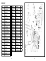
1
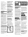
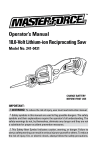
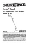
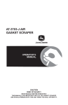
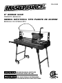
709-3932
8" BRIDGE SAW
OWNER’S MANUAL
SIERRA ELÉCTRICA TIPO PUENTE DE 203MM
MANUAL DE OPERACIÓN
READ AND FOLLOW ALL SAFETY AND
OPERATING INSTRUCTIONS BEFORE USING THIS SAW.
LEA Y SIGA TODAS LAS INSTRUCCIONES
DE FUNCIONAMIENTO Y SEGURIDAD ANTES DE USAR ESTA SIERRA.
236418
8" BRIDGE SAW
English . . . . . . . . . . . . . . . . . . . . . . . . . . . . . . . . . . . . . . . . . . . . . . . . . . . . . . . . . . . . . . . . . . . page 1
For your own safety, read instruction manual
before operating saw.
1. Always wear safety goggles when cutting.
2. Use blade guard for everyoperation for which it can be used.
3. Disconnect saw before cleaning or changing blade.
4. Do not use any cutting blade with openings and grooves. Use only continuous rim blades.
5. R
eplace damaged blade before operating.
6. D
o not expose to rain or use in damp locations.
Limited Warranty — Refer to warranty card.
Customer Service: 1-866-435-8665
Español . . . . . . . . . . . . . . . . . . . . . . . . . . . . . . . . . . . . . . . . . . . . . . . . . . . . . . . . . . . . . . . página 23
Lee esta instuccion manual antes
de usa la sierra para tu bien.
1. Siempre utilice gafas de protección al cortar.
2. Utilice una capota de protección para cada operación en la cual la puede utilizar.
3. Desconectar la sierra antes de limpiarla o antes de cambiar el disco de corte.
4. No utilice ningún disco de corte que tenga aperturas o ranuras. Solamente utilice discos de
corte lisos.
5. Reemplace el disco de corte cuando esté dañado.
6. No la exponga a la lluvia o no la utilice en áreas húmedas.
GARANTIA LIMITADA — Referirse a la tarjeta de guarantia.
Servicio al cliente: 1-866-435-8665
OWNER’S MANUAL
TABLE OF CONTENTS
8. USE THE RIGHT TOOL. Don’t force a tool
or attachment to do a job for which it was
not designed.
9. USE THE PROPER EXTENSION CORD.
Make sure your extension cord is in good
condition. When using an extension cord,
be sure to use one heavy enough to carry
the current your product will draw. An
undersized cord will cause a drop in line
voltage resulting in loss of power and
overheating. Table 1 (page 4) shows the
correct size to use depending on cord
length and nameplate ampere rating. If
in doubt, use the next heavier gauge. The
smaller the gauge number, the heavier
the cord. 10. Don’t force the tool. It has been
designed to operate at maximum safety and
performance levels.
11. Do not force the material being cut.
Always let the blade cut at its own speed.
12. Wear proper apparel. Do not wear
loose clothing, neckties, rings, bracelets
or other jewelry which may get caught
in moving parts. Non-slip foot wear is
recommended. Wear protective hair
covering if you have long hair.
13. Always use safety glasses. Also use
face or dust mask for commercial cutting
operations. Everyday eyeglasses only have
impact-resistant lenses, they are NOT
safety glasses.
14. Don’t overreach. Keep proper footing
and balance at all times.
15. Maintain tools with care. Keep tools
clean and in good working condition for
maximum safety performance.
16. Disconnect SAW before servicing
– when changing accessories, such as
blades, bits, cutters, etc.
17. Reduce the risk of unintentional
starting. Make sure switch is in OFF
position before plugging in.
18. Use recommended accessories.
Consult the owner’s manual for
recommended accessories. The use of
improper accessories may increase risk
of injury.
General Safety Instructions . . . . . . . . 1-3
Warning . . . . . . . . . . . . . . . . . . . . . . . . . . . 3
Electrical Requirements . . . . . . . . . . . 3-4
Extension Cords . . . . . . . . . . . . . . . . . . . . 4
California Proposition 65 . . . . . . . . . . . . . 4
Description . . . . . . . . . . . . . . . . . . . . . . . . 5
Assembly . . . . . . . . . . . . . . . . . . . . . . . . 5-7
Functional Description
and Operation . . . . . . . . . . . . . . . . . . . . 7-9
Maintenance . . . . . . . . . . . . . . . . . . . .9-10
Troubleshooting . . . . . . . . . . . . . . . . 10-11
Parts List . . . . . . . . . . . . . . . . . . . . . . . . . 12
Exploded Parts . . . . . . . . . . . . . . . . . . . . 13
GENERAL SAFETY
INSTRUCTIONS
Read this owner's
manual completely and make
sure you understand all of it's
safety guidelines.
1. Keep guards in place and in
working order.
2. Remove adjusting keys and
wrenches. Before turning on the tile
saw, make sure the keys and adjusting
wrenches have been removed.
3. Keep work area clean. Cluttered areas
and benches invite accidents.
4. Always remain alert when the saw
is in use. Inattention on the part of the
operator may lead to serious injury.
5. Don’t use in a dangerous
environment. Don’t use power tools in
damp or wet locations or expose them to
rain. Keep work area well lit.
6. Keep children away. All visitors should
remain at a safe distance from work area.
7. Make workshop child-proof with
padlocks, master switches or by removing
starter keys.
–1–
19. Do not dry cut with blades
designed for wet cuts.
20. Make sure you use the correct blade
for the job you are doing.
21. Never stand on tool. Serious injury
could occur if the wet saw is tipped or if the
cutting tool is unintentionally contacted.
22. Check damaged parts. Before further
use of the tool, damaged part(s), (i.e.,
guard) should be carefully checked to
determine that it will operate properly
and perform its intended function. Check
for alignment of moving parts, binding of
moving parts, breakage of parts, mounting
and any other condition that may affect the
saw’s operation. A guard or other part that
is damaged should be properly repaired
or replaced.
23. Ensure that blade is traveling
through water reservoir for wet
cutting.
24. Check diamond blades carefully for
cracks, nicks, missing diamond matrix
or out-of-alignment condition. Replace
damaged blades immediately. DO NOT
USE DAMAGED BLADES. They may cause
bodily injury.
25. Direction of feed. Feed work into the
blade against the direction of rotation of
the blade only.
26. Do not alter the plug or use a 2-prong
receptacle. This saw is equipped with a
3-prong electrical plug.
27. Never leave SAW running
unattended. Turn power off. Don’t leave
tool until it comes to a complete stop.
28. POSITIONING OF TILE SAW (see Figure 1)
• To avoid the possibility of the appliance plug
or receptacle getting wet, position the tile
saw to one side of a wall-mounted receptacle
to prevent water from dripping onto the
receptacle or plug. The user should arrange
a “drip loop” in the cord connecting the saw
to a receptacle. The “drip loop” is that part
of the cord below the level of the receptacle,
or connector if an extension cord is used, to
prevent water traveling along the cord and
coming in contact with the receptacle.
• If the plug or receptacle does get wet, DO
NOT unplug the cord. Disconnect the fuse
or circuit breaker that supplies power to the
tool. Then, unplug and examine for presence
of water in the receptacle.
POWER
SUPPLY CORD
TOOL
4. Improper connection of the
equipment-grounding conductor
can result in a risk of electric
shock. The conductor with insulation that
is green on the outside (with or without
yellow stripes) is the equipment-grounding
conductor. If repair or replacement of
the electrical cord or plug is necessary,
do not connect the equipment-grounding
conductor to a live terminal.
5. Check with a qualified electrician
or service personnel if the grounding
instructions are not completely understood,
or if in doubt as to whether the tool is
properly grounded.
6. Use only 3-wire extension cords that
have 3-prong grounding plugs and 3-pole
receptacles that accept the tile saw’s plug.
7. Repair or replace damaged or worn
cord immediately.
8. If the plug or receptacle does
get wet, do not unplug the cord.
Disconnect the fuse or circuit breaker that
supplies power to the tool. Then, unplug
and examine for presence of water in the
receptacle.
9. Only UL-listed extension cords
should be used with this product.
10. Improper use of extension cords
may cause inefficient operation
of your tool, which can result in
overheating. Be sure your extension cord
is rated to allow sufficient current flow to
the motor. For the proper gauge for this tile
saw, please refer to TABLE 1 (page 4).
11. Do not let your fingers touch the
terminals of plug when installing or
removing the plug to or from the outlet.
12. This tile saw must be properly
grounded. The risk of electric shock
and bodily injury are greatly increased if
it is not, particularly when used in damp
locations or in proximity to plumbing.
NOTE: This saw is intended for use on a
circuit that has a grounded outlet box like
the one illustrated in FIGURE 2 (B). This saw
has a grounding plug that looks like the one
illustrated in FIGURE 2 (A).
13.Never allow the blade to run dry. Failure to
keep the water tray at the recommended
level will result in possible over-heating of
the diamond blade.
Warning
PERSONAL INJURY CAN OCCUR IF OPERATED
IMPROPERLY.
DRIP LOOP
FIGURE 1
SPECIFIC OPERATION GUIDE
1. Ensure that the directional arrow marked
on the blade corresponds with the
rotational direction of the motor.
2. With the saw disconnected from the power
supply, rotate the blade by hand to ensure it
is free from obstruction.
3. Always keep the blade-securing arbor and
collars clean.
4. Ensure that the blade-securing bolt is
securely tightened.
5. Never try to cut freehand. Always ensure
that the tile to be cut is pressed firmly
against the rip fence.
6. Ensure that the workpiece that will be cut
off has sufficient room to move sideways.
Failure to do so may result in the off-cut
binding against the blade.
7. Never cut more than one tile at a time.
8. Never cut pieces too small that are not held
securely against the rip fence, and provide
enough space for the hand to be a safe
distance from the blade.
9. Ensure that the table and surrounding area
are clear with the exception of the tile to
be cut.
10.Before cutting a tile piece, let the saw
blade run freely for a few seconds. If it
makes an unfamiliar sound or vibrates
excessively, switch it off immediately and
disconnect it from the power supply.
11.Let the blade reach full speed before
commencing the cut.
12.Let the blade come to a complete stop
before removing any jammed material from
around the blade area.
–2–
• Keep fingers and loose clothing away from
rotating blade.
• Use extreme caution when cutting tile. Make
sure hands and fingers are clear from the
blade groove in the table. Severe abrasion,
cuts, or pinching of hands or fingers can
occur as the table is advanced, particularly at
the end of its travel.
• Electrical shock can occur if operating
instructions are not followed.
FOR YOUR OWN SAFETY READ INSTRUCTION
MANUAL BEFORE OPERATING SAW.
• Wear eye protection.
• Use blade guard for every operation for which
it can be used.
• Unplug saw before servicing, when changing
cutting wheels, and cleaning.
• Use tool only with smooth-edge cutting
wheels free of openings and grooves.
• Replace damaged cutting wheel
before operating.
• Do not fill water tray above water fill line.
ELECTRICAL REQUIREMENTS
1. This tile saw must be connected to a
grounded power source while in use to
protect the operator from electrical shock.
2. In the event of a malfunction or
breakdown, grounding provides a path
of least resistance for electrical current to
reduce the risk of electrical shock. This tile
saw is equipped with an electrical cord with
a grounding conductor and a grounding
plug. Insert the 3-prong electrical plug into
a 3-pole receptacle that is properly installed
and grounded in accordance with all local
codes and ordinances.
3. Do not modify the plug provided if it
will not fit the outlet. Have the proper outlet
installed by a qualified electrician.
–3–
Volts
Ampere rating
25 ft.
More than
No more than
0
6
6
10
120 V
Total length of cord in feet
50 ft.
100 ft.
AWG
150 ft.
18
16
16
14
16
14
16
12
TABLE 1
cause a drop in line voltage, resulting in loss
power and overheating. TABLE 1 shows the
correct size to use depending on cord length
and nameplate ampere rating. If in doubt, use
the next heavier gauge. The smaller the
gauge number, the heavier the cord.
Note: When using an extension cord, ensure
all cords are no smaller than #12 gauge, rated
at a 20-amp minimum, and equipped with
3-prong plugs. Use of anything smaller may
result in overheating or burn out of the motor. It
is recommended to have an electrician check
the voltage at the saw motor to ensure proper
voltage to run the saw efficiently and safely.
Metal
screw
(A) Grounding pin
(B) Grounded
outlet box
FIGURE 2
EXTENSION CORDS
Plunge cutting head for
making interior cuts
Flexible cord rod keeps
encapsulated power
cords safely away from
the cutting table
Steel blade guard
accommodates both 8” and
7” blades (8” continuous rim
diamond blade included)
Adjustable pivoting rail
for quick and easy 45°
and 90° miter cuts and
bevel cuts
1-1/2HP, 10A inductor motor
is powerful and long lasting
Adjustable
pull-out handle
Pull-out side
extension table
supports large format
tiles and slabs
Universal quick-adjust angle
guide and rip fence for quick
and accurate miter cuts from
0° to 45°
Rubber matting
provides a slip resistant
working surface
Large locking wheels for
easy jobsite transport
Durable folding stand
for convenient storage
and transportation
Innovative water transport
system makes water fill-ups
and drainage clean, fast and
efficient (requires standard
garden hose, sold separately)
FIGURE 3
1. Use only extension cords that are intended
for outdoor use. These extension cords are
identified by a marking “Acceptable for use
with outdoor appliances: store indoors while
not in use.” Use only extension cords having
an electrical rating not less than the rating of
the product. Do not use damaged extension
cords. Examine extension cord before using
and replace if damaged. Do not abuse
extension cords and do not yank on any cord
to disconnect. Keep cord away from heat and
sharp edges. Always disconnect the extension
cord from the receptacle before disconnecting
the product from the extension cord.
CALIFORNIA
PROPOSITION 65
Some dust created
by power sanding, sawing, grinding,
drilling and other construction
activities contain chemicals known to
the State of California to cause cancer,
birth defects or other reproductive
harm.
Some examples of these chemicals are:
• Lead from lead-based paints
• Crystalline silica from bricks, cement and other
masonry products
• Arsenic and chromium from chemicallytreated lumber
Your risk from these exposures varies,
depending on how often you do this type
of work. To reduce your exposure to these
chemicals: work in well ventilated area, and
work with approved safety equipment, such as
those dust masks that are specifically designed
to filter out microscopic particles.
To reduce the risk
of electrocution, keep all connections
dry and off the ground. Do not touch
plug with wet hands.
2. Ground Fault circuit Interrupter (GFCI)
protection should be provided on the
circuit(s) or outlet(s) to be used for the tile
saw. Receptacles are available having built-in
GFCI protection and may be used for this
measure of safety.
3. Use proper extension cord. Make sure
your extension cord is in good condition.
When using an extension cord, be sure to use
a cord heavy enough to carry the current your
product will draw. An undersized cord will
Description
Before attempting to use any tool, be sure
to familiarize yourself with all the operating
features and safety instructions.
–4–
KNOW YOUR SAW
Your tile saw has many built-in features (see
figure 3) for fast, efficient cutting of ceramic,
porcelain, marble, slate or limestone wall or floor
tile. The durable 8 inch blade cuts tile up to 1-1/2 in.
thick. The built-in handle allows easy transporting.
PRODUCT SPECIFICATIONS
Input: 11.3 Amps
No-load Speed: 3420 RPM
Output: 1-1/3 HP Motor
Blade Diameter: 8 in. (203 mm)
Arbor: 5/8 in.
Rating: 120 Volts~60 Hz AC
Depth of Cut: 1 3/8 in. (35 mm)
Cutting Capacity: 30" at 90°, 21" at 45°
Assembly
Follow all of the
Assembly and operation Instructions
completely before connecting the saw
to a power source or turning the motor
on.
UNPACKING
1. Remove all packing materials from around your
saw.
–5–
2. Carefully lift the saw from carton and place
it on a level work surface.
3. Do not discard the packing materials until
you have carefully inspected the saw for
loose or damaged parts.
The following items are included in box with
your tile saw:
• Folding stand
• Universal Angle Guide
• 8 in. premium continuous rim diamond b lade
• 2 wrenches
•Hex key
• Water pump
•Water tray
•Extension table
4. Inspect the saw carefully to make sure
that no breakage or damage has occurred
during shipping. If any parts are damaged
or missing, return the saw to your place of
purchase.
If any parts are
damaged or missing, DO NOT attempt
to operate this saw. Operating this
saw with damaged or missing parts
could result in possible serious
personal injury.
7. Micro adjustment for perfect level.
8. To mount the handle position the handle on
the trolley and secure it using the 2 screws
(Fig 7).
STARTING AND STOPPING
1. Connect the unit to a power supply of the
correct voltage and frequency (120V-60HZ).
2. To start the saw press the switch to the
“ON” position (Fig 4).
3. To stop the saw, press the switch to the
“OFF” position (Fig 4)
wood sawing blades, blades with
openings, or any other cutting devices
with this tile saw. Using these blades
could result in serious personal
injury and damage to the saw.
MAKING A STRAIGHT CUT
For your own
safety, always position the switch
to the “OFF” position when the saw
is not in use. In the event of a power
failure, blown fuse or tripped circuit
breaker, press switch to the “OFF”
position. This will prevent the tool
from starting up again when the
power comes back on.
1. Push the motor trolley away from the
operator until it reaches the stroke limit.
2. Position the tile on the cutting table.
3. Properly set the measuring guide and
squaring tool (Fig 9).
FIGURE 5-1
4. Pull out the stand legs (Fig 5-1).
FIGURE 7
5. Stand the saw upright.
9. The motor trolley is secured during
shipment, please loosen lever before using
(Fig 8).
FIGURE 9
FIGURE 4
1. Clean the working area.
2. Remove saw from carton, you will find
it assembled.
3. Lay the saw on its side on the ground (Fig 5).
FIGURE 5-2
6. Tighten thumb screw to secure legs (Fig 6).
4. Pull the motor trolley slowly towards the
material to be cut (Fig 10).
FIGURE 8
FILLING THE WATER TRAY
AND DRAINING
1. Fill the tray with water between minimum
and maximum water line. Do not add
chemicals or detergents to the water.
2. To drain, remove the plug from the inside of
the tray, the water will flow out or you can
remove the tray and pour the water out
FIGURE 6
FIGURE 5
The tray can also be filled with the hose
attached under the water tray with a
gentle flow.
FIGURE 10
6. When you have completed the cut push
motor trolley/blade away and remove the
cut pieces, and any debris on cutting
surfaces.
Operation
Use only
continuous rim blades with this saw.
DO NOT use segmented, “turbo” blades,
–6–
–7–
2. REPLACING THE SAW BLADE
A. Loosen the blade guard thumb screw
(Fig 15).
MAKING A DIAGONAL CUT
1. Follow the same procedure for a straight cut.
2. Loosen the nut on the squaring tool, and
position the tile diagonally.
3. Lock the nut and perform the cut following
procedure for a straight cut.
ANGLED OR 45 DEGREE CUTS
1. Loosen the two knobs at either end of the
bridge (Fig 11)
.
Maintenance
3. DO inspect the arbor shaft for uneven wear
before mounting the blade.
4. DO use blades with the correct arbor size on
a compatible arbor shaft.
5. DO ensure the blade is mounted with the
rotation arrow in the proper direction and is
securely tightened with a wrench.
6. DO wear proper safety equipment at all
times when operating the saw. Wear
goggles and dust mask at all times when
operating saw.
7. DO periodically check the blade for cracks
or bond fatigue.
8. DO ensure that blade is traveling through
water reservoir for wet cutting.
9. DO NOT operate the saw without all safety
guards in position.
10.DO NOT operate the saw with blades larger
or smaller than recommended.
11.DO NOT cut dry with blades marked
“Use Wet.”
12.DO NOT exceed maximum RPMs
recommended by the blade manufacturer.
13.DO NOT force the material into the blade.
Let the blade cut at its own speed.
14.DO NOT cut material not recommended by
the blade manufacturer.
To avoid accidents,
ALWAYS disconnect the tool from
the power source BEFORE cleaning or
performing any maintenance
Please do not try to service this machine on
your own.
Avoid using solvents when cleaning plastic
parts. Most plastics are susceptible to damage
from various types of commercial solvents
and may be damaged by their use. Use clean
cloths to remove dirt, carbon dust, etc.
FIGURE 12
FIGURE 11
2. Tilt bridge to the desired angle up to 45 degrees
(Fig 13). Tighten knobs at either end of bridge,
and proceed with cutting tile following same
procedure as listed in the “straight cut”
section.
C. Use the hexagonal wrench to hold the
blade nut and use the spanner wrench
provided to hold the shaft. Loosen the nut
turning clockwise as in (Fig 13).
D. Ensure that the shaft and flanges are
clean. Mount blade back on to shaft
ensuring that the directional arrow on the
blade is rotating towards the material to
be cut.
E. Insert flange and lock nut. Tighten
counterclockwise.
CHANGING THE BLADE
Disconnect the power
supply before making adjustments,
maintenance, cleaning or replacing the
blade!
1. CHOICE OF THE SAW BLADE. Only use 8 Inch
continuous rim or turbo blades with a 5/8 Inch
arbor.
FIGURE 13
–8–
DO NOT at any time
let brake fluids, gasoline, petroleumbased products, penetrating oils, etc.
come in contact with plastic parts.
They contain chemicals that can
damage, weaken or destroy plastic.
1. ALWAYS clean the tile saw after each use
and store it in a dry location.
2. ALWAYS wipe off all exterior surfaces and
keep the cutting table clean and free of
all debris.
3. ALWAYS check the blade for cracks or
damage BEFORE each use.
4. ALWAYS store the cord in the compartment
underneath the saw after each use.
TROUBLESHOOTING
OVERHEATING OF SAW:
1. Turn saw off and let it rest until motor is cool
to the touch.
2. Check and clean the ventilation slots,
removing blockage and dirt.
DIAMOND BLADES
• Use only 8 in. (203 mm) continuous rim
diamond blades with a 5/8" arbor opening in
this saw. Failure to do so may result in severe
bodily injury and damage to the saw.
• The diamond blade that comes with this saw
will cut ceramic, porcelain and marble tile.
Due to the hardness of some porcelain, slate
and stone, purchasing a blade specifically
designed to cut these hard tiles, will speed
up the cutting time required. IMPORTANT:
Always let the blade cut at its own speed,
moving the material slowly into the blade. Do
not force the material being cut.
DIAMOND BLADE DO’s & DON’Ts
1. DO inspect blades daily for cracks or
uneven wear. Discard cracked, chipped or
bent blades!
2. DO use manufacturer’s recommendation
for matching the right blade with the right
material being cut.
THE SAW DOES NOT START:
1. Check that power cord is properly plugged in.
2. Check outlet power source and circuit
breaker.
3. Make sure yellow safety key is fully pushed
into switch.
What to do when the
alignment is off on the BRIDGE
SAW:
The 709-3932 Masterforce 8” Bridge Saw motor
or bridge does not need to be squared up or
aligned, since the bridge does not allow the saw
–9–
motor to move. When it appears that the saw is
out of alignment, it is the rip fence that needs to
be squared up.
Tools needed:
24” Framing Square, Phillips Screw Driver and
¼” Nut Driver or Pliers
The following steps should be used to align the
rip fence for the Bridge Saw:
1. Pull the power unit towards you and lock in
place with the transport screw.
2. Once the power unit is secured, place the
Framing square firmly against the blade on the
left side of the cutting surface. The square
must be flush with the blade. (See Image A).
4. To adjust the gap, first remove the Angle cutting
guide. This will expose two screws in the
aluminum track. Loosen both screws in the
extruded aluminum bar. (See Image C & D)
5. From underneath the saw, directly below the rip
fence, there are two ¼” bolts located under the
left rip fence and 2 bolts under the right rip
fence. Loosen both bolts for the rip fence that
you are adjusting. (See Images E & F)
Right
Rip Fence
¼" Bolts
IMAGE E
Gap
6. Once the screws are loose, easily slide the
rip fence above, allowing you to close the
gap between the square and the rip fence.
When the square is flush against the rip
fence re-tighten the two ¼” bolts from the
side you are adjusting. If necessary, repeat
the same steps for the other side. (See
Image G)
IMAGE C
Rip
Fence
IMAGE F
Left
Rip Fence
IMAGE AIMAGE B
3. Slide the square into the rip fence, making
sure the square stays firmly against the
blade. Look for a gap between the square and
the rip fence. If there is a gap, adjustments
will be necessary. (See Image B)
IMAGE G
7. Once both rip fences are secured in place
slide the extruded aluminum angle bar firmly
against both rip fences and tighten in place
for additional support.
IMAGE D
Customer Service:
1-866-435-8665
– 10 –
– 11 –
PARTS LIST
DESCRIPTION
83250-1
Water Spray Guard
QTY
PART #
DESCRIPTION
1
83250-24
Knob
1
QTY
83250-2
Outer Blade Guard
1
83250-25
Left Rail Stand
1
83250-3
Nut
1
83250-26
Butterfly Knob
1
83250-4
Outside Flange
1
83250-27
Protection Plastic Tube
1
5-8008BW
8 Inch Porcelain Blade
1
83250-28
Resetable Sheet
1
83250-6
Inside Flange
1
83250-29
Slide Rail
1
83250-7
Waterproof Gasket
1
83250-30
Right Rail Slide
1
83250-8
Inside Blade Guard
1
83250-31A
Decorated Board
1
83250-9
Handle
1
83250-31B
Left Decorated Board
1
83250-10A
Motor Fixture
1
83250-31C
Right Decorated Board
1
83250-10B
Water Pipe Connector
1
83250-32
Table II
1
83250-11
Motor
1
83250-33
Measuring Guide
1
83250-12
Pull-out Handle
1
83250-34
Water Tray
1
83250-13A
Decorated Board I
1
83250-35A
Front Fence
1
83250-13B
Decorated Board II
1
83250-35B
Rear Fence
1
83250-14A
Left Rail Stand Fixture
1
83250-36
Main Frame
1
83250-14B
Right Rail Stand Fixture
1
83250-37
Right Stand
1
83250-15
Water Spray Board
1
83250-38
Foot Pad
1
83250-16
Hex Nut
1
83250-39
Foot Wheel System
1
83250-17
Knob
1
83250-40
Left Stand
1
83250-18A
Connecting House
1
83250-41
Butterfly Knob
1
83250-18B
Capacitor
1
83250-42
Extension
1
83250-18C
Connecting House Cover
1
83250-43
Water Tube
1
83250-18D
Switch
1
83250-44
Pump Cable
1
83250-18E
Circuit Breaker
1
60098
Cooling Water Pump
1
83250-19
Cable Lock
1
83250-45B
O Ring
1
83250-20
Power Cable
1
83250-45C
Pump Connector
1
83250-21
Position Bar
1
83250-46
Motor Shaft Wrench
1
83250-22A
Lock Bar
1
83250-47
Hexagonal Blade Wrench
1
83250-22B
Ball Bearing Trolley
1
83250-23A
Spring Shaft
1
83250-23B
Punching Cutting System
1
– 12 –
EXPLODED PARTS
PART #
– 13 –
SIERRA ELÉCTRICA
TIPO PUENTE
DE 203MM
MANUAL DE OPERACIÓN
CONTENIDO
Instrucciones generales de seguridad . . 27-28
Advertencia . . . . . . . . . . . . . . . . . . . . . . . . . .28-29
Requerimientos eléctricos . . . . . . . . . . . . . 29-30
Cables de extensión (alargadores) . . . . . . . . . 30
Proposición 65 de California . . . . . . . . . . . . . . 30
Descripción . . . . . . . . . . . . . . . . . . . . . . . . . . 30-31
Montaje . . . . . . . . . . . . . . . . . . . . . . . . . . . . . 31-33
Operación . . . . . . . . . . . . . . . . . . . . . . . . . . . 33-35
Mantenimiento . . . . . . . . . . . . . . . . . . . . . . . 35-36
Localización de averías . . . . . . . . . . . . . . . 36-37
Lista de piezas . . . . . . . . . . . . . . . . . . . . . . . . . . 38
Despiezado . . . . . . . . . . . . . . . . . . . . . . . . . . . . . 39
INSTRUCCIONES GENERALES
DE SEGURIDAD
Lea este
manual del usuario en su totalidad y
asegúrese de entender todas las pautas
de seguridad.
1. MANTENGA LAS PROTECCIONES EN SU
LUGAR y con el orden apropiado para trabajar.
2. REMUEVA LAS LLAVES DE AJUSTE Y LAS
LLAVES INGLESAS. Antes de encender la sierra
eléctrica para cortar losetas asegúrese que haya
quitado las llaves inglesas y las llaves de tuercas
de ajuste.
3. MANTENGA LIMPIA SU ÁREA DE TRABAJO.
Los accidentes suelen ser más comunes en las
áreas que estén desordenadas o por bancas en el
área de trabajo.
4. MANTÉNGASE ALERTA AL UTILIZAR LA
SIERRA. La falta de atención por parte del
operador puede ocasionar accidentes graves.
5. NO LA UTILICE EN AMBIENTES PELIGROSOS.
No utilice herramientas eléctricas en lugares
húmedos o mojados, ni las exponga a la lluvia.
Mantenga bien iluminada el área de trabajo.
6. MANTENGA A LOS NIÑOS ALEJADOS. Todos
los visitantes deben mantenerse a una distancia
considerable del área de trabajo.
7. ARME SU LUGAR DE TRABAJO A PRUEBA
DE NIÑOS, utilizando candados, interruptores
principales, o quitando las llaves de encendido.
8. UTILICE LA HERRAMIENTA CORRECTA. No
intente utilizar herramientas o accesorios para
realizar un trabajo, en el cual la herramienta no
ha sido diseñada para esa función.
9. UTILICE UN CABLE DE EXTENSIÓN
ADECUADO. Asegúrese de que el cable de
extensión está en buenas condiciones. Cuando
utilice un cable de extensión, asegúrese de que
sea lo suficientemente pesado para transportar
la corriente que requerirá el producto. Un cable
de menor tamaño al requerido causará una caída
en el voltaje de paso y dará como resultado la
pérdida de energía y el recalentamiento. La tabla
(ver la Tabla 1 en la página 26) muestra el tamaño
correcto que debe usarse, teniendo en cuenta la
longitud del cable y la clasificación de amperios
de la placa de datos. Si tuviera dudas, utilice el
siguiente indicador más pesado. Cuanto menor
sea el número del indicador, más pesado será el
cable.
10. NO FUERCE LA HERRAMIENTA. Ha sido
diseñada para funcionar a niveles de máxima
seguridad y rendimiento.
11. NO FUERCE EL MATERIAL QUE DEBE CORTAR.
Siempre deje que la cuchilla corte a la velocidad
para la que fue diseñada.
12. UTILICE UNA VESTIMENTA ADECUADA. No
use ropa suelta, corbatas, anillos, pulseras, u
otros artículos de joyería que pudieran quedar
atrapados en las partes móviles. Se recomienda
usar calzado antideslizante. Use una cubierta
protectora para el cabello si lo tuviera largo.
13. SIEMPRE USE GAFAS DE PROTECCIÓN.
También use máscaras protectoras para la
cara y el polvo en el caso de operaciones de
corte comercial. Las gafas comunes sólo tienen
cristales resistentes a los impactos, pero NO son
gafas de seguridad.
14. NO TRATE DE EXTENDERSE MÁS DE LO
NECESARIO. Mantenga su posición y el equilibrio
en todo momento.
15. MANTENGA LAS HERRAMIENTAS EN BUEN
ESTADO. Mantenga las herramientas limpias y
en buen estado para trabajar para obtener un
máximo rendimiento de seguridad.
– 14 –
16. DESCONECTE LA SIERRA ELÉCTRICA ANTES
DE HACERLE ALGÚN ARREGLO – al cambiar
accesorios, como cuchillas, puntas, elementos
cortantes, etc.
17. REDUZCA EL RIESGO DE UN ENCENDIDO
INVOLUNTARIO. Asegúrese de que la
herramienta se encuentra en posición de
APAGADO antes de enchufarla.
18. UTILICE LOS ACCESORIOS RECOMENDADOS.
Consulte el manual del usuario para los
accesorios recomendados. El uso de accesorios
inadecuados puede ocasionar accidentes.
19. NO REALICE CORTES EN SECO CON DISCOS
DE DIAMANTE DISEÑADOS PARA REALIZAR
CORTES CON AGUA.
20. ASEGÚRESE DE USAR LA CUCHILLA
CORRECTA para el trabajo que está realizando.
21. NUNCA SE APOYE SOBRE LA HERRAMIENTA.
Puede tener un accidente grave si la herramienta
se mueve o si se toma contacto involuntario con
la parte cortante.
22. REVISE LAS PARTES DAÑADAS. Antes de
volver a utilizar la herramienta debe revisar
cuidadosamente la(s) parte(s) dañada(s),
(por ejemplo la protección), para saber si
funcionará en forma adecuada y cumplirá con
su función. Revise la alineación de las partes
móviles, la unión de las mismas, si se rompieron,
superpusieron y cualquier otra condición que
pueda afectar el funcionamiento de la sierra. Las
protecciones u otras partes que estén dañadas
deben repararse o reemplazarse adecuadamente.
23. Asegúrese que el DISCO DE CORTE ESTÉ
PASANDO A TRAVÉS DE LA RESERVA DE AGUA
PARA OBTENER UN CORTE EN HÚMEDO.
24. REVISE CUIDADOSAMENTE LOS DISCOS
DE DIAMANTE en caso de grietas, rajaduras,
que la matriz de diamante falte o que esté
desalineado. Reemplace las cuchillas dañadas
inmediatamente. NO USE DISCOS DAÑADOS.
Pueden causar accidentes graves.
25. DIRECCIÓN DE LA ALIMENTACIÓN. Solamente
coloque el trabajo en la cuchilla en dirección
contraria a la rotación de la cuchilla.
26. NO ALTERE EL ENCHUFE O USE UN
TOMACORRIENTE DE 2 PUNTAS. Esta sierra está
equipada con un enchufe eléctrico de 3 puntas.
27. NUNCA DEJE LA SIERRA ELÉCTRICA
ENCENDIDA SIN PRESTARLE ATENCIÓN.
Apáguela. No deje la herramienta hasta que se
haya detenido completamente.
28. COLOCACIÓN DE LA SIERRA ELÉCTRICA PARA
LOSETAS (ver el FIGURA 1)
CABLE DE
ALIMENTACIÓN
ELÉCTRICA
SIERRA PARA
LOSETA
VUELTA DE GOTEO
FIGURA 1
• Para evitar que el tomacorriente o enchufe
del accesorio se humedezcan, coloque la
sierra eléctrica para losetas hacia un lado del
tomacorriente que se encuentra en la pared,
para que el agua no caiga sobre éste o el
enchufe. El usuario debería realizar una "vuelta
de goteo" en el cable que conecta la sierra al
tomacorriente. La "vuelta de goteo" es la parte
del cable por debajo del nivel del tomacorriente,
o el conector si se utiliza un cable de extensión,
que evita que el agua se deslice por el cable y
entre en contacto con el tomacorriente.
• Si el enchufe o el tomacorriente se
humedecieren, no desenchufe el cable.
Desconecte el fusible o el interruptor automático
que suministra electricidad a la herramienta.
Luego desenchúfela y revise si hay agua en el
tomacorriente.
ADVERTENCIA
EL USO INADECUADO PUEDE OCASIONAR
GRAVES ACCIDENTES.
• Mantenga los dedos y la ropa que esté suelta
alejados del disco de diamante giratorio.
• Sea sumamente cuidadoso al cortar losetas.
Asegúrese de que las manos y los dedos estén
alejados de la ranura de la cuchilla en la mesa.
Puede rasparse, cortarse o apretarse los dedos
gravemente mientras la mesa está en movimiento,
generalmente al finalizar su trayectoria.
• Si no se siguen las instrucciones de
funcionamiento puede producirse una descarga
eléctrica.
PARA SU SEGURIDAD LEA EL MANUAL
DE INSTRUCCIONES ANTES DE PONER EN
FUNCIONAMIENTO LA SIERRA.
– 15 –
• Use protección para los ojos.
• Use una máscara protectora siempre que
sea necesario.
• Desconecte la sierra antes de hacerle alguna
reparación, cuando le cambie los discos de
diamante, y antes de limpiarla.
• Use la herramienta sólo con discos de
diamantes que tengan los de bordes libres de
aberturas y ranuras.
• Reemplace el disco de diamante que
esté dañado antes de poner la sierra en
funcionamiento.
• No llene la bandeja de agua por encima de la
línea marcada para llenarlo.
REQUERIMIENTOS
ELÉCTRICOS
6. UTILICE SOLAMENTE CABLES DE EXTENSIÓN
DE 3 CONDUCTORES que poseen enchufes
de conexión polo a tierra de 3 puntas y
tomacorrientes de 3 polos que aceptan el
enchufe de la sierra eléctrica para cortar losetas.
7. REPARE O REEMPLACE INMEDIATAMENTE EL
CABLE GASTADO O DAÑADO.
8. SI EL ENCHUFE O TOMACORRIENTE SE
HUMEDECIERAN, NO DESENCHUFE EL CABLE.
Desconecte el fusible o el interruptor automático
que suministra electricidad a la herramienta.
Luego desenchúfela y revise si hay agua en el
tomacorriente.
9. CON ESTE PRODUCTO SÓLO PUEDEN USARSE
CABLES DE EXTENSIÓN CALIFICADOS POR UL.
10. EL USO INADECUADO DE CABLES
DE EXTENSIÓN PUEDE PRODUCIR UN
FUNCIONAMIENTO DEFICIENTE DE LA
HERRAMIENTA, que puede dar como resultado
el recalentamiento. Asegúrese de que el cable
de extensión tenga la potencia adecuada para
suministrar una corriente eléctrica suficiente
al motor. Para calibrar su herramienta en forma
adecuada consulte el TABLA 1 (página 26).
11. NO TOQUE CON LOS DEDOS las terminales del
enchufe al conectar o desconectar el enchufe
del toma.
12. ESTA SIERRA ELÉCTRICA PARA
CORTAR LOSETAS DEBE SER INSTALADA
APROPIADAMENTE POLO A TIERRA. Si no
lo estuviera aumentaría enormemente el
riesgo de descargas eléctricas y accidentes,
particularmente si se utilizara en lugares
húmedos o cercanos a cañerías.
NOTA: La sierra electrica professional esta
diseñada para ser conectada en un toma
corriente empotrado y conectado a tierra como el
que se encuentra en la FIGURA 2(B). Ademas esta
sierra tiene un toma corriente de tierra como el
de la FIGURA 2(A).
1. ESTA SIERRA ELÉCTRICA PARA LOSETAS DEBE
TENER UNA CONEXIÓN POLO A TIERRA mientras
está en uso para evitar que el operador sufra una
descarga eléctrica.
2. EN EL CASO DE MAL FUNCIONAMIENTO O
FALLA ELÉCTRICA, la conexión polo a tierra
proporciona un suministro de menor resistencia
de corriente eléctrica para reducir el riesgo
de una descarga eléctrica. Esta herramienta
está equipada con un cable eléctrico con un
conductor con conexión polo a tierra y un
enchufe con conexión polo a tierra. Conecte
el enchufe eléctrico de 3 puntas a una toma
de 3 polos debidamente instalado y con una
conexión polo a tierra conforme a los códigos y
regulaciones locales.
3. NO MODIFIQUE EL ENCHUFE SUMINISTRADO
si éste no se adapta la toma. Instale la toma
adecuado con la ayuda de un electricista
profesional.
4. LA CONEXIÓN INADECUADA DEL CONDUCTOR
CON LA CONEXIÓN POLO A TIERRA DEL EQUIPO
PUEDE OCASIONAR UNA DESCARGA ELÉCTRICA.
El conductor con aislamiento que posee una
superficie externa verde (con o sin franjas
amarillas) es el conductor de conexión polo a
tierra del equipo. Si fuera necesario reparar
(A) Pernos
o reemplazar el cable eléctrico o enchufe no
de tierra
conecte el conductor de conexión polo a tierra
del equipo a una terminal activa.
5. CONSULTE A UN ELECTRICISTA PROFESIONAL
si no entendiera completamente las instrucciones
para la conexión polo a tierra; o si tuviera dudas FIGURA 2
acerca de si la herramienta está conectada
correctamente polo a tierra.
– 16 –
Tornillo
de
metal
(B) Toma corriente
empotrado
y conectado a tierra
Voltios
Régimen de amperios
Más de
No más de
0
6
6
10
7,62 m
120 V
18
16
Longitud total del cable en pies
15,24 m
30,48 m
45,72 m
AWG
16
16
14
14
16
12
TABLA 1
CABLES DE EXTENSIÓN
(ALARGADORES)
un calibre menor al # 12, con una potencia de
20-amperios como mínimo, y estén equipados
con enchufes de 3 puntas. El uso de cualquier
cable menor puede ocasionar el recalentamiento
o que se queme el motor. Se recomienda que
un electricista revise el voltaje en el motor de la
sierra para asegurarse de que tiene el voltaje
adecuado para que la sierra funcione de manera
eficaz y segura.
1. Utilice solamente los cables de extensión
destinados para uso en áreas exteriores. Puede
identificarlos con la leyenda “Pueden usarse
con dispositivos para exteriores: guardar en el
interior cuando no se use.” Utilice solamente los
cables de extensión que tengan una clasificación
eléctrica no menor a la clasificación del producto.
No utilice el cable de extensión si está dañado,
reemplácelo. Examine el cable de extensión antes Proposición 65
de California
de usarlo y suspenda el uso si está dañado. No
maltrate el cable de extensión y no lo desconecte
de un tirón. Mantenga el cable alejado del calor
Algunos
y los bordes filosos. Siempre desconecte el
polvos creados por lijadoras
cable de extensión del tomacorriente antes de
mecánicas, aserraderos, trituradores,
desconectar el producto del cable de extensión.
perforadoras y otras actividades de
construcción contienen sustancias
Para reducir
químicas que se sabe (en el Estado de
el riesgo de electrocución, mantenga
California) causan cáncer, defectos de
todas las conexiones secas y lejos
nacimiento u otros daños al sistema
del suelo. No toque el enchufe con las
reproductivo.
manos mojadas.
Algunos ejemplos de estas sustancias químicas
2. El/los circuito/s o toma/s que se usarán con la son:
sierra para losetas/azulejos deben contener un
• Plomo derivado de pinturas a base de plomo.
Interruptor de Circuito Polo a Tierra (GFCI) como
• Sílice cristalino de los ladrillos, cementos y
protección. Se pueden obtener tomacorrientes
otros tipos de productos de albañería.
con protección GFCI incorporada para usarse de
•
Arsénico y cromo de madera tratada con
acuerdo con esta medida de seguridad.
sustancias químicas.
3. UTILICE UN CABLE DE EXTENSIÓN
El
riesgo de exposición a éstas situaciones varía,
ADECUADO. Asegúrese de que el cable de
dependiendo de cuantas veces se hace este
extensión esté en buenas condiciones. Cuando
tipo de trabajo. Para reducir el contacto con
utilice un cable de extensión, asegúrese de que
estas sustancias químicas: trabaje en lugares
sea lo suficientemente pesado para transportar
la corriente que requiera el producto. Un cable de bien ventilados y con equipos aprobados para
tamaño reducido causará una caída en el voltaje la protección, como mascarillas para el polvo
que son diseñadas especificamente para filtrar
de paso, y dará como resultado la pérdida de
energía y el recalentamiento. La TABLA muestra partículas microscopias.
el tamaño correcto que debe usarse, teniendo en
cuenta la longitud del cable y la clasificación de
amperios en la placa de datos. Si tuviera dudas, Descripción
utilice el siguiente indicador más pesado. Cuanto
Antes de intentar utilizar cualquier herramienta
menor sea el número del indicador, más pesado
asegúrese que esté familiarizado con todas
será el cable.
las características de operación y con las
NOTA: Cuando utilice un cable de extensión,
instrucciones de seguridad.
asegúrese de que todos los cables no tengan
– 17 –
CONOZCA SU SIERRA
Su sierra para cortar losetas tiene muchas
características integradas (ver la Figura 3) para
cortar rápidamente y eficientemente cerámica,
porcelana, mármol, pizarra, piedra caliza para
pared o losetas para piso. El disco de corte de
180 mm es de larga duración, corta losetas que
tengan un grosor hasta de 31 mm.
ESPECIFICACIONES DEL PRODUCTO
Entrada: 11.3 Amperios
Velocidad sin carga: 3420 RPM
Salida: 1-1/3 máximo de cabllos de fuerza
Diámetro del disco de corte: 203 mm
Eje: 16 mm
Rango: 120 Voltios, 60 Hercios
Profundidad del Corte: 35 mm
Capacidad del Corte: 762mm at 90°, 533mm at 45°
Montaje
Siga todas las
instrucciones acerca del montaje e
instalación que están en éste manual,
antes de conectar la sierra para
cortar losetas en la toma eléctrica
y encenderla.
Varilla flexible para
los cables mantiene
los cables eléctricos
encapsulados y seguros,
lejos de la mesa de corte
DESEMPAQUE
1. Remueva todos los materiales de empaque que
están alrededor de su sierra.
2. Con cuidado levante la sierra y sáquela del
cartón colocándola en una superficie que esté
al nivel para trabajar.
3. No deseche los materiales de empaque hasta
que usted no haya inspeccionado bien la sierra
si llegará a tener alguna parte suelta o dañada.
Los siguientes artículos están incluidos en la caja
con su sierra para cortar losetas:
• Soporte plegable
• Guía universal para ángulos
• Disco de corte diamantado de banda continua
de 200 mm de calidad superior
• 2 Llaves inglesas
• Llave hexagonal
• Bomba para el agua
• Bandeja para el agua
• Mesa de extensión
4. Inspeccione cuidadosamente la sierra para
asegurarse que durante el transporte no se
haya roto a dañado. Si alguna parte está
dañada o le falta alguna parte regrese la sierra
al lugar donde la compró.
Cabeza para cortes
penetrantes para realizar
cortes interiores
Riel pivoteable y
ajustable para realizar
fácilmente cortes a
inglete y biselados a
45° y 90°
Motor de inducción de 1-1/2HP,
10A es potente y duradero
Manija retirada
ajustable
Mesa de extensión
lateral extraíble
proporciona soporte
para las losetas
grandes y las lajas
Almohadilla de caucho
proporciona una superficie
de trabajo resistente a los
deslizamientos
Ruedas bloqueables
grandes para
transportarla fácilmente
en el área de trabajo
Protección en acero, para el
disco de corte acomoda discos
de corte de 200 mm y de 180 mm
(Se incluye un disco de corte
diamantado de banda continua
de 200 mm)
Soporte plegable
muy duradero para
un almacenamiento y
transportación conveniente
FIGURA 3
Si alguna parte
está dañada o le hace falta, NO intente
utilizar esta sierra. Si utiliza esta sierra
con alguna parte dañada o sin una parte
que le haga falta, podría resultar en una
seria lesión personal.
ARRANQUE Y PARADA
1. Conecte la unidad a una fuente de energía de
voltaje y corriente correctos (120V-60HZ).
2. Para arrancar la sierra coloque el interruptor
en la posición “ON” (Fig. 3).
3. Para detener la sierra, coloque el interruptor
en la posición “OFF” (Fig. 3).
Para su propia
seguridad, siempre coloque el interruptor
en la posición “OFF” cuando no utilice
la sierra. En el caso de un corte de
energía, fusible fundido o cortacircuito
desconectado, coloque el interruptor
en la posición “OFF”. Evitará que la
herramienta vuelva a arrancar cuando
se restablezca el suministro de energía.
FIGURA 5-1
4. Saque las patas del estante
5. Coloque la sierra en posición vertical.
FIGURA 5-2
6. Tornillo de ajuste con el dedo pulgar, para
asegurar las patas. (Fig 5-2).
FIGURA 4
1. Limpie el área de trabajo.
2. Retire la sierra de la caja de cartón, la
encontrará armada.
3. Apoye la sierra sobre un costado en el suelo
(Fig 5).
Guía universal para ángulos de
ajuste rápido y tope-guía para
realizar cortes rápidos y
precisos a inglete desde 0° a 45°
FIGURA 6
Innovador sistema para
transportar el agua permite
rellenar con agua y drenar el
agua de una manera limpia,
rápida y eficiente (Requiere de
7. Micro ajustes para una nivelación perfecta.
(Fig 6).
una manguera estándar de
jardinería, se vende por separado)
FIGURA 5
– 18 –
– 19 –
OperaCIÓN
8. Para montar la empuñadura, colóquela
sobre el carro y asegúrela mediante 2
tornillos (Fig 7).
Con esta
sierra, solamente utilice discos de
corte con banda continua. NO utilice
discos de corte con banda segmentada,
turbo, para cortar madera, con
aberturas o con ningún otro artículo
para cortar con esta sierra. Si utiliza
éste tipo de discos de corte podría
causar lesiones personales muy serias
y dañar la sierra.
FIGURA 7
PARA HACER UN CORTE DIAGONAL
1. Siga el mismo procedimiento que para hacer
un corte recto.
2. Afloje la tuerca de la herramienta para
escuadrar y coloque la loseta en posición
diagonal (Fig. 12).
3. Trabe la tuerca y realice el corte siguiendo el
procedimiento para un corte recto.
CORTES EN ÁNGULO O A 45 GRADOS
1.Afloje las dos perillas de cualquiera de los
extremos del puente (Fig 12).
PARA HACER UN CORTE RECTO
1. Empuje el carro del motor lejos del operador
hasta que llegue al límite de la carrera.
2. Coloque la loseta sobre la mesa de corte.
3. Coloque correctamente la guía de medición
y la herramienta para escuadrar (Fig 9).
9. El carrillo del motor se mantiene asegurado
durante su transporte, por favor afloje la
palanca antes de utilizarlo. (Fig 8).
FIGURA 15
FIGURA 12
FIGURA 9
2. Incline el puente al ángulo deseado hasta los
45 grados (Fig. 13). Ajuste las perillas a ambos
extremos del puente y corte la loseta siguiendo
el mismo procedimiento que se describe en la
sección de “corte recto”.
4. Empuje el carro del motor lentamente hacia
el material a cortar (Fig 11).
CAMBIO DEL DISCO
FIGURA 8
LLENADO Y DESAGOTE DE LA
BANDEJA PARA AGUA
1. Llene la bandeja con agua entre la línea que
marca mínimo y la línea que marca máximo. No
agregue ningún químico ni detergente al agua.
2. Para el drenaje, remueva el tapón que está
dentro de la bandeja, el agua fluirá hacia afuera
o usted también podrá remover la bandeja y
dispersar el agua hacia afuera.
También podrá rellenar la bandeja con la
manguera adjuntada debajo de la bandeja,
utilizando un flujo leve.
2. REEMPLAZO DEL DISCO DE LA SIERRA
A. Retire la protección del disco quitando
los 2 tornillos (Fig 15).
C. Utilice la llave hexagonal para sostener la
tuerca del disco y use la llave con
salientes suministrada para sujetar el eje.
Afloje la tuerca girándola en el sentido de
las agujas del reloj como se muestra en la
(Fig 16).
D. Asegúrese de que el eje y las pestañas
estén limpios. Monte la parte posterior
del disco sobre el eje, asegurándose de
que la flecha direccional del disco rote en
dirección al material a cortar.
E. Introduzca la pestaña y trabe la tuerca.
Ajústela en sentido contrario a las agujas
del reloj.
¡Desconecte
la fuente de energía antes de hacer
ajustes, realizar el mantenimiento,
limpiar o reemplazar el disco!
1. ELECCIÓN DEL DISCO DE LA SIERRA.
Únicamente use discos de borde continuo o
turbo de 203 mm con un mandril de sujeción de
159 mm.
FIGURA 11
FIGURA 16
5. Una vez que haya completado el corte, aleje
el carro del motor/disco, y retire las piezas
cortadas y cualquier residuo que haya
sobre las superficies de corte.
– 20 –
– 21 –
MANTENIMIENTO
moviendo el material lentamente hacia el
disco de corte. No fuerce el material que esté
cortando.
Para evitar
accidentes, SIEMPRE desconecte la
sierra de la fuente de electricidad
ANTES de limpiarla o hacerle algún
mantenimiento.
QUÉ HACER Y QUÉ NO HACER CON
EL DISCO DE DIAMANTE
1. Revisar los discos de diamante diariamente
en caso de roturas o desgaste desparejo.
¡No utilizar discos de diamante rotos,
astilladas o dobladas!
2. Seguir siempre las recomendaciones del
fabricante para utilizar la cuchilla adecuada
para el material que se desea cortar.
3. Revisar el eje en caso de desgaste
desparejo antes de colocar el disco
de diamante.
4. Usar siempre discos de diamante con
el tamaño de eje adecuado en un eje
compatible.
5. Asegurarse de que se colocó el disco de
diamante con la flecha de rotación en
la dirección correcta y que está sujeto
firmemente con la llave de tuerca.
6. Usar siempre el equipo de seguridad
adecuado al operar la sierra. Usar gafas
protectoras y máscara para el polvo en todo
momento.
7. Revisar periódicamente la cuchilla en caso
de roturas o fatiga del material.
8. Asegúrese que el disco de corte esté
pasando a través de la reserva de agua para
realizar el corte en húmedo.
9. No opere la sierra sin colocar todos los
elementos de seguridad en posición.
10.No use la sierra con discos de diamante
más grandes o más pequeños que los
recomendados.
11.No haga cortes en seco con cuchillas
marcadas para “Usar con Agua”.
12.No exceda del máximo de RPM
recomendadas por el fabricante de la
cuchilla.
13.No fuerce el material dentro de la cuchilla.
Dejar que la cuchilla corte a su propia
velocidad.
14.No corte materiales distintos a los
recomendados por el fabricante de la
cuchilla.
Por favor no intente hacerle algún servicio a
esta sierra usted solo.
Evite utilizar solventes cuando esté limpiando
las parte plásticas. La mayoría de las partes
plásticas son susceptibles a dañarse a causa
de varios tipos de solventes comerciales y
también podrían dañarse por su uso. Utilice un
trapo limpio para remover mugre, polvo etc.
NUNCA
permita que líquidos para frenos,
gasolina, productos a base de
petróleo, aceites penetrantes etc.,
entren en contacto con las partes
plásticas. Estos contienen químicos
que pueden dañar, debilitar o
destruir plástico.
1. SIEMPRE limpie la sierra para losetas
después de cada uso y guarde la sierra para
losetas en un área seca.
2. SIEMPRE limpie todas las superficies
exteriores y mantenga la mesa de corte limpia
y libre de desechos.
3. SIEMPRE revise el disco de corte a ver si
tiene grietas o demuestra algún signo de estar
dañado ANTES de cada uso.
4. SIEMPRE guarde el cable en el
compartimiento que está en la parte de abajo
de la sierra después de cada uso.
DISCOS DE DIAMANTE
• Utilice en esta sierra solamente un disco de
diamante de banda continua de 180 mm con
un apertura de eje de 16 mm. De no ser así
podría resultar en causarse daños físicos o
dañar la sierra.
• El disco de corte diamantado que viene con
ésta sierra cortará losetas de cerámica,
porcelana y mármol. Dado a la dureza de
la porcelana, la pizarra y la piedra, puede
comprar un disco de corte específicamente
diseñado para estos materiales, para
acelerar el tiempo de corte requerido.
IMPORTANTE: Siempre permita que el disco
de corte haga el corte a su propio ritmo,
– 22 –
LOCALIZACIÓN DE AVERÍAS
Cerca para
corte recto
SOBRECALENTAMIENTO
DE LA SIERRA:
1. Apague la sierra eléctrica tipo puente y déjela
en reposo hasta que el motor esté frío al tacto.
2. Verifique y limpie las ranuras de ventilación,
quite cualquier obstrucción y suciedad.
LA SIERRA NO ARRANCA:
1. Verifique que el cable de alimentación esté
enchufado correctamente.
2. Revise la fuente de energía de la toma
eléctrica y el corta circuito.
3. Asegúrese que la llave amarilla de seguridad
esté completamente empujada hacia el
interruptor.
Qué hacer cuando la sierra
Sierra Eléctrica Tipo Puente
está desalineada:
El motor o el puente de la sierra eléctrica de
puente 709-3932 Masterforce Sierra Eléctrica Tipo
Puente de 203mm no requieren ser escuadrados o
alineados, ya que el puente no permite que el
motor se mueva. Cuando la sierra aparente estar
desalineada, es la cerca para corte recto que
debe ser escuadrada.
Herramientas requeridas:
Escuadra de 60 cm
Destornillador Phillips
Aprieta tuercas de 6 mm o unas pinzas
Brecha
IMAGEN AIMAGEN B
3. Deslice la escuadra en la cerca para corte
recto, asegurándose que la escuadra quede
firmemente contra la cuchilla. Busque a ver si
hay vacíos entre la escuadra y la cerca para
corte recto. Si hay vacíos deberá realizar
ajustes. (Ver la imagen B)
4. Para ajustar el vacío, primero remueva la guía
para corte en ángulo. Esto expondrá los dos
tornillos en el tramo de aluminio. Afloje ambos
tornillos que están en la barra de aluminio
extruido. (Ver la imagen C y D)
Deberá seguir los siguientes pasos para alinear
la cerca para corte recto de la Sierra Eléctrica
Tipo Puente:
1. Jale la unidad de potencia hacia usted y
bloquéela en su lugar, utilizando el tornillo de
transporte.
2. Una vez haya asegurado la unidad de potencia,
coloque la escuadra firmemente contra el
disco de corte, en el costado izquierdo de la
superficie de corte. La escuadra deberá
quedar a ras con el disco de corte. (Ver la
imagen A)
– 23 –
Cerca para
corte recto
a la derecha
6. Una vez haya aflojado los tronillos, deslice
fácilmente la cerca para corte recto de arriba,
permitiéndole cerrar el vacío entre la escuadra
y la cerca para corte recto. Cuando la
escuadra se encuentre a ras contra la cerca
para corte recto, vuelva ajustar los dos pernos
de 6 mm del costado que se encuentre
ajustando. Si es necesario, repita los mismos
pasos para el otro costado. (Ver las imágen G)
IMAGEN C
Cerca para
corte recto
a la izquierda
IMAGEN D
5. Desde la parte de debajo de la sierra,
directamente debajo de la cerca para corte
recto, hay dos pernos de 6 mm ubicados
debajo de la cerca de corte recto del lado
izquierdo y 2 pernos debajo de la cerca de
corte recto del lado derecho. Afloje ambos
pernos de la cerca de corte recto que usted
está ajustando. (Ver la imágenes E y F)
IMAGE G
7. Una vez ambas cercas para corte recto estén
aseguradas en su lugar, deslice la barra
angular de aluminio extruido firmemente
contra ambas cercas para corte recto y
apriete en su lugar para obtener soporte
adicional.
Servicio al cliente:
1-866-435-8665
IMAGEN E
Pernos
de 6 mm
LISTA DE PIEZAS
Ver el diagrama de las partes en la página 26.
PIEZA
DESCRIPCIÓN
Cant.
83250-1
Protección contra salpicaduras
de agua
1
83250-2
Protector exterior del disco
1
83250-3
Tuerca
1
83250-4
Pestaña externa
1
5-8008BW
Disco de diamante de 203mm
1
83250-6
Pestaña interna
1
83250-7
Junta impermeable
1
83250-8
Protector interior del disco
1
83250-9
Manija
1
83250-10A
Fijación del motor
1
83250-10B
Conector para tubo de agua
1
83250-11
Motor
1
83250-12
Manija retirada ajustable
1
83250-13A
Tablero decorado I
1
83250-13B
Tablero decorado II
1
83250-14A
Fijación del soporte del riel izquierdo
1
83250-14B
Fijación del soporte del riel derecho
1
83250-15
Tablero para rocío de agua
1
83250-16
Tuerca hexagonal
1
83250-17
Perilla
1
83250-18A
Manguera de conexión
1
83250-18B
Capacitor
1
83250-18C
Cubierta para manguera de
conexión
1
83250-18D
Interruptor
1
83250-18E
Cortacircuito
83250-19
PIEZA
DESCRIPCIÓN
Cant.
83250-23B
Sistema de corte por punzonado
1
83250-24
Perilla
1
83250-25
Soporte del riel - izquierdo
1
83250-26
Perilla mariposa
1
83250-27
Protección para tubo de plástico
1
83250-28
Hoja reajustable
1
83250-29
Riel de deslizamiento
1
83250-30
Riel de deslizamiento - derecho
1
83250-31A
Tablero decorado
1
83250-31B
Tablero decorado - izquierdo
1
83250-31C
Tablero decorado - derecho
1
83250-32
Mesa II
1
83250-33
Guía de medición
1
83250-34
Bandeja para agua
1
83250-35A
Valla frontal
1
83250-35B
Valla trasera
1
83250-36
Bastidor principal
1
83250-37
Soporte derecho
1
83250-38
Almohadilla de pata
1
83250-39
Sistema de ruedas de pie
1
83250-40
Soporte izquierdo
1
83250-41
Perilla mariposa
1
83250-42
Extensión
1
83250-43
Tubo de agua
1
83250-44
Cable de la bomba
1
60098
Bomba de agua
1
1
83250-45B
Anillo toroidal de goma
1
Cable de bloqueo
1
83250-45C
Conector de la bomba
1
83250-20
Cable de energía eléctrica
1
83250-46
Llave del eje del motor
1
83250-21
Barra de posición
1
83250-47
Llave hexagonal para discos
1
83250-22A
Barra de bloqueo
1
83250-22B
Bola carro que lleva
1
83250-23A
Eje de resorte
1
IMAGEN F
– 25 –
NOTES | NOTAS
DESPIEZADO
________________________________________________________________
________________________________________________________________
________________________________________________________________
________________________________________________________________
________________________________________________________________
________________________________________________________________
________________________________________________________________
________________________________________________________________
________________________________________________________________
________________________________________________________________
________________________________________________________________
________________________________________________________________
________________________________________________________________
________________________________________________________________
________________________________________________________________
________________________________________________________________
________________________________________________________________
________________________________________________________________
________________________________________________________________
________________________________________________________________
________________________________________________________________
________________________________________________________________
________________________________________________________________
________________________________________________________________
________________________________________________________________
________________________________________________________________
________________________________________________________________
________________________________________________________________
________________________________________________________________
________________________________________________________________
________________________________________________________________
– 26 –
– 27 –
NOTES | NOTAS
NOTES | NOTAS
________________________________________________________________
________________________________________________________________
________________________________________________________________
________________________________________________________________
________________________________________________________________
________________________________________________________________
________________________________________________________________
________________________________________________________________
________________________________________________________________
________________________________________________________________
________________________________________________________________
________________________________________________________________
________________________________________________________________
________________________________________________________________
________________________________________________________________
________________________________________________________________
________________________________________________________________
________________________________________________________________
________________________________________________________________
________________________________________________________________
________________________________________________________________
________________________________________________________________
________________________________________________________________
________________________________________________________________
________________________________________________________________
________________________________________________________________
________________________________________________________________
________________________________________________________________
________________________________________________________________
________________________________________________________________
________________________________________________________________
________________________________________________________________
________________________________________________________________
________________________________________________________________
________________________________________________________________
________________________________________________________________
________________________________________________________________
________________________________________________________________
________________________________________________________________
________________________________________________________________
________________________________________________________________
________________________________________________________________
________________________________________________________________
________________________________________________________________
________________________________________________________________
________________________________________________________________
________________________________________________________________
________________________________________________________________
________________________________________________________________
________________________________________________________________
________________________________________________________________
________________________________________________________________
________________________________________________________________
________________________________________________________________
________________________________________________________________
________________________________________________________________
________________________________________________________________
________________________________________________________________
________________________________________________________________
________________________________________________________________
________________________________________________________________
________________________________________________________________
– 28 –
– 29 –
Made in China
Fabriqué en Chine
Hecho en China
Boca Raton, FL 33487
www.qep.com
A0315-9167
– 30 –