1
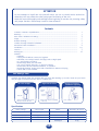
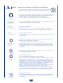
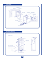
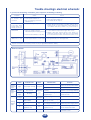
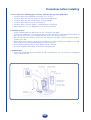
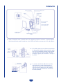
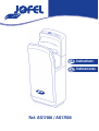
GB Instructions
CAS Instrucciones
Ref. AG17000 / AG17500
ATTENTION
Do not attempt to install the unit yourself unless you are a trained service technician.
Otherwise, this may affect the safety and proper functioning of the unit.
Read this manual thoroughiy and carefully before beginning to use the unit, ensuring safety
and proper function. Please keep it well for later reference.
Contents
Contents > Features > Specifications.......................................................................................
Warning...................................................................................................................................
Parts narne > Dimension drawing...........................................................................................
Usage ......................................................................................................................................
Routine cleaning.....................................................................................................................
Trouble shooting > Electrical schematic..................................................................................
Precaution before installation ................................................................................................
Installation..............................................................................................................................
Test run...................................................................................................................................
Packing list .............................................................................................................................
Features
• Features
• Drying hands without contact, it's hygienic
• Electricity cost saving because of drying hands at high speed.
• It's economical & practical.
• Anti-damage timer, use unworried
• Do not use towels & tissues, no dispose of waste
• Anti-bacteria & environmental materials, no pollution
• Automatic heating, drying hands with comfortable in winter and drying
• Hands with cool in summer
2
3
4
5
6
7
8
8-9
9
10
Anti-damage timer
Installed anti-damage timer, this machine will stop work after working 25 seconds. Draw out your hands
and put again your hands into the dryer to continue use.
1. No need windpipe.
2. High and low sensors.
3. Design in accordance
with human engineering.
stopping
sensor
starting
sensor
drain tank
• Separate airsupply, quite hygienic.
• No drip comes info the unit.
• Prevent water drops from spattering
on the body.
• Ease of use.
Specifications
Rated voltage
AC220-240V
Motor
Brushless DC motor
Inputpower
1650-2050W
Induction method
IRblocking
Wind velocity
95M/S
Protection class
IPX4
Heating power
1000-1200W
Dimensions
330 x 220 x 687 mm
Netweight
11 Kg
GB
A
WARNING
O
Personal injury accidents will happen if use improperly.
• Do not open the front panel, otherwise, this may get an electric shock.
• Children forbidden hanging on the machine, there are risk of falling.
• Do not use in a wet environment, for example, near the bathroom where it
may get the direct water and the places where the condensation may form,
otherwise, this may cause electric shock and unit malfunction.
• Do not allow the unit get wet.otherwise, it will cause electric shock.
Prohibited
Do not use in
the bathtub or
shower room
• Do not modify and disassemble the unit unnecessarily. Otherwise, this may
cause a fire, electric shock, or personal injury.
Donotallow
The unit getwet
• Rated power is required.
• If power tolerance is over +/-10%, there will be breakdown If using incorrect
power supply, fire, electric shock and machine malfunction will happen.
Prohibit
disassembling
• Please use dedicated socket.
If using together with other appliances, the socket may cause abnormal heat
leading to fire.
O
• Power must be cut off when maintenance to prevent the risk of electric shock.
• Drain tank and air filter must be installed.
Do not switch on after power connected for 10 seconds.
• If the machine doesn't work or have abnormal conditions, please cut off
power to prevent accidents; and cióse leakage circuit breaker and ask supplier
to check and repair, or it may lead to fire because of electricity leakage and
short circuit.
Please do
complying with
instruction
©
O
• It must have the reliable grounding wire otherwise it may cause electric shock
risk when the unit failure or leakage.
Ground
WARNING
• Attention when installation:
Do not install when the machine are power connected.
• It must operated by the professional construction person when install the
unit If the construction incorrect, it may cause electric shock and fire accident.
• This appliance is not intended for use by persons (including children) with
reduced physical, sensory or mental capabilities, or lack of experience and
knowledge, unless they have been given supervisión or instruction concerning
use of the appliance by a person responsible for their safety.
If the cord is damaged, it must be replaced by the manufacturer, its service
agent or similarly qualified persons in order to avoid a hazard.
Foradditional protection, the installation of a residual current device (RCD)
having a rated residual operating current not exceeding 30mAis advisable in
the electrical circuit supplying the bathroom. ask your installer for advice.
• Environmental Protection.
Waste electrical products should not be disposed of with household waste.
Please recycle where facilities exist. Check with your Local Authority or retailer
for recycling.
GB
Parts name
Heating button
Power supply
Speed button
Drying time and
fault display
Power indicator
Self-check indicator
Hand drying area
Lamp
Sensor
Drain hose
Power switch
Air filter
Drain tank
Unit
Full level indicator
Dimension drawing
Terminal Box location
Installation Panel
Power Cord hose (rear)
Terminal Box location
Drain Tank
Air Filter
GB
Usage
Using the Unit
• Stretch out both hands and insert them all the way in. The unit starts to run
automatically.
• Pulí them out slowly, letting the air blow the water off.
t
• Pulí them out completely.
Self-check indicator
When a malfunction or error occurs, the self-check indicator on the right side will either light up or flash.
Turn off the power switch, wait about 40 seconds until all the indicators go off, then turn on the power
switch.
If the indicator still lights up or flashes, turn off the power, disconnect the unit from the socket, and contact
your dealer immediately.
Usage Label
Stick the usage label on the visible place
(the front of the unit or the wall nearby).
How to use the "Air Injection" Hand Dryer.
Dry your hands about "7" seconds.
♦
When using the unit.
Turn on the power switch.
• The power indicator lights up.
• The lamp lights up.
• The cover of power supply is closed.
GB
Routine Cleaning
Cleaning the Unit body
Before it gets obviously dirty
Clean the unit with a soft cloth.
If the unit gets very dirty, clean with a soft cloth dampened
with neutral agent, then clean with a dry soft cloth.
Remove the dirt from the sensor, (to prevent malfunction).
Note
WARNING
• Before you clean the unit, tum off the
power switch.
• Do not splatter water on the unit.
• Only use the neutral cleaning agents.
• Do not use thinner, acidic or alkaline toilet
cleaners, or nylon brush. (Otherwise, they may
damage the smoothness of surface).
Only use the alcohol to clean the hand-drying
área. (Do not use alcohol anywhere else).
• Alcohol here means the alcohol used for
disinfection (concentration below 83%).
• If the chemical cloths used, please read their
instructions first.
• Disinfecting agents will damage your unit.
-A<
Caution
The antibacterial coating is effective when the bacteria
exposed the coated surfaces (See the shade áreas on the
figure) The antibacterial coating becomes not effective when
the surfaces get very dirty.
Draining and Cleaning the drain tank
Before it filis up (at least once a week)
Cleaning the air filter
Around once a week
• The water blown off the hands is called "drain water".
• Empty the drain water at any moment, in order to prevent
accumulated water from exceeding the full level.
• It will start smelling if the accumulated water remains in
the tank for too long time.
Remove the air filter.
• Pull the air filter out by the handle.
Handle
Pull the drain tank out in the
horizontal direction.
This ensures the drain water
does not splatter out.
Full level
1. Open the cover and empty
the water.
• Pull the cover up with your
fingers in the direction of
the arrow on top of the
cover, and then remove the
cover completely.
1. Cleaning the air filter.
• Beat it lightly by hand or use a
vacuum cleaner.
• If it is very dirty, wash it off with
cold or warm water.
Air filter
Full level
2. Wash out the interior of the
drain tank.
3. Close the water tank
cover, and Re-attach it to the
unit as original.
• Confirm the
two locations
are firmly
inserted.
Cover
2. Re-attach to the unit.
• Insert it all the way in, until it
stops.(If it is not in place, the dirt
or dust will enter the unit and
shorten its service life.)
Full level
Add 200cc (around 1 cup) of water
through the drain hole. (to prevent
it from getting clogged).
• Use the unit after confirming that
the water tank is in place.
Note
GB
• If you wash the air filter with water,
and dry it as much as possible.
• Do not expose to the fire.
Trouble shootingn electrical schematic
If you discover the following circumstance, please inspection and handling as following:
Problem
Check
No air blows even
if hands are
inserted
• Do the display indicators lights up?
• Is the power switch on?
• Are you putting your hands
alltheway in?
• Turn the ground-fault circuit breaker on.
• Turn the power switch on.
• Put hands all the way in.
Machine works
long time after
hands drawn out,
finally shows E2
• Anydirtorforeign body on sensor?
• Switch off the power button, and then remove dirt or
foreign body on sensor after the power light gone
out. When finished, switch on power button.
Nohotwind
• There is a Built-in heater
intheunit.Anydirton heating sensor?
• Fuse inside terminal box blown?
• Is the ambient temperature higher than 20°C?
• Switch off power, remove front cover. There is a
terminal box inside. Take down the cover of terminal
box. Check the fuse inside box which is blown or not.
• Is the speed button on low level?
• Put speed button on the high level.
Airflow is too low
Action
If the above actions do not work, tum off the power and the ground-fault circuit breaker, and cali your dealer to
inspect and repair it if necessary. (Costs are as per agreement with the dealer)
Electrical schematic
STATUS
Power
indicator
light
STATUS
INTRODUCTIONS
SOLUTION
Power not supply
Light
Extinguish
State
indicator
light
always
light
Digital
changes
Timing
digital
tube
INTRODUCTIONS
Check the external power
source, close the power switch
Power input normally Extinguish
Master board fuse blew out
Don't work
Flashing
light
Working
Countdown work
Motor fault, it can't start
normally
Check motor connecting wires
and the rotor foreign material
Tr i c k o r w o r k i n g
longerthan25s
Clearworkspace foreign material,
restart to work
time
Jump
displayBB
Indicate drying time finished
E1
Motor fault, it can't
start normally
E2
Trick or working time longer
than 25 seconds
Lights ablaze with state
E3
The voltage exceeds
15%
E4
The voltage lower than 15%
Check the power supply circuit
E5
Machine temperatures
higherthan 80t;
E6
Master board temperatures
higherthan 801)
Clear the foreign material of
the air inletand airoutlet
Fan fault
Check whether the Fan sensor
connectis loosen
E8
GB
Precautions before installing
I Do not install in the following types of location, otherwise this may cause malfunction:
•
•
•
•
•
•
Locations where the temperature can exceed -10° C or 40° C.
Locations where the unit may come into direct contact with water.
Locations where the unit is under direct or strong sunlight.
Locations where there is a lot of condensation.
Locations where corrosive, neutral, or reductive gases are present.
Places lower than -20 m or higher than 2.000 m above sea level.
I Installation location
• Install somewhere the unit will be easy to use, as shown in the figure.
If the unit is installed too low, water may get on it when the floor is being cleaned (the bottom of
the unit must be at least 150 mm higher than the floor or any objects under it).
• The left side of the unit must be at least 150 mm away from any walls, because the power switch is
located on the left.
• Ensure there are no mirrors or walls near the right side, as drops of water may splatter to the right
when drying hands (recommended distance is at least 100 mm).
• Avoid locations where people or doors might bump into the unit.
• Choose a completely fíat surface on the wall to install the unit.
I Installation Base
• If your space is limited and the condition of wall is unsatisfactory, you can purchase an installation
base to install this unit.
Power indicator
Self-check indicator
Power supply
Unit
Fixed screws
Installation panel
Power switch
Installation heights
(Recommended)
890 mm (for man)
870 mm (for woman)
Front panel
installation screws
Drain tank
GB
Air filter
Installation Procedures
I Use a single-phase alternating rated voltage supply. (Do not be used with a power supply exceeding
rated voltage +
_ b110%.) I Use a power cord which is between 2mm2 and 2.5mm2
thick. (Cords other than 2mm2 - 2.5mm2 single-core cords cannot be used.)
(A drop in voltage is possible if the power cord exceeds 11 m in length, so we
recommend using a 2.5mm2 cord.)
Wire the unit.
Embed the switchbox in the installation location (1 switchbox no cover) and
wire the power cord (with the green and yellow combined is ground line).
• If no switchbox is used, the power cord will be
pushed out, and prevent the unit from being
installed firmly against the wall.
Attach the installation panel to the wall using the 6
installation screws.
• If the wall is concrete, use commercially available
metal screw plugs (curl plugs, etc.).
• If the wall is not concrete, reinforce it before installation.
1. Remove the drain tank.
2. Remove the front panel.
(1) Remove the two screws.
(2) Remove all the front panel
chuckholes (3).
Chuckhole
3. Remove the terminal box cover.
Remove the terminal box cover screw
and pull the cover out towards you.
Terminal box
cover
Terminal box Lock clutch
Lock clutch
Drain tank
Nit
Screw
Front panel
Screw
Pull the separate line power cord into the unit and secure
inside.
Pull this machine has been with power cord. if you want to
change, please according to the following steps. (1) Pull the
power cord through the power cord hole on the rear of the
unit, attach the rear side to the 3 hooks on the installation
panel, and secure with the installation screws (temporarily
fixed on the unit side) while pushing the unit against the
wall lightly. • The installation screws for the unit will not
tighten completely if the hooks at the bottom of the installation
panel are not in place. Ensure the lower hooks are completely
hooked onto the rear of the unit.
Note: Ensure the unit is hooked on the installation panel, tightened the
safety screws (at the low right), otherwise, this may cause the unit to drop
and be in the danger of theft.
GB
Power socket
Upper hook
Power cord
Power cord
Installation
panel
Lower hook
Installation screw
Stafety screw
Installation Procedures
Wire the terminal box. (There is no polarity.)
Screw
Terminal box
Clip
(1) Strip the wire sheath as shown in the figure at right.
(2) Loosen the screws on the terminal box and connect the
power cord to the terminal box.
(3) Remove the protective seal attached to the terminal
box before connecting the ground wire.
(4) Tighten the screws on the terminal box and pull the
power cord to make sure it is secured firmly.
(5) Bind the power cord using the clip to the right of the
terminal box and fix it to its original location.
Power cord
Ground
line
®
Protective seal
Attach the terminal box cover.
Terminal
box cover
Lock
clutch
(1) Place the terminal box tabs into the holes and retum
the cover to its original position,securing it with the
screw.
(2) Make sure the power cord and other wires are not
pinched.
• The front panel cannot be attached if there are any
wires in front of the terminal box cover. Move the
wires to the right of the terminal box cover.
Nit
Screw
1. Attach the front panel.
(1) Insert the 3 front Panel chuckholes into the unit.
(2) Replace the 2 screws that were removed.
Front panel
Installation screw
2. Attach the drain tank.
Drain tank
Air filter
3. Make sure the air filter is all the way in.
Step
Check
1
Check the voltage of power supply
Please use the rated voltage?
2
Turn the ground-fault circuit breaker on
3
Turn the power switch on
Does the power indicator light up?
4
Dry hands
Is the air blowing?
GB
Result
CAS Instrucciones
Manual de uso e instalación
de las Secadoras de Manos
¡ ATENCIÓN !
• La instalación debe ser ejecutada por un técnico cualificado en conformidad con
las normativas en vigor.
• Antes de cualquier manipulación eléctrica, cortar la corriente.
• Antes de efectuar la instalación, verificar que la ubicación elegida está conforme
con la distancia de seguridad prevista en la normativa CEI*.
• El aparato no puede ser instalado sobre una superficie normalmente inflamable.
• Es necesario instalar un interruptor de corte omnipolar con apertura entre contactos
de 3 mm en la instalación fija de la vivienda según las normas de instalación vigentes
en Europa.
* Ejemplo distancia normativa CEI.
V473
100 cm min.
CAS
Nomenclatura
Botón de activación del aire caliente
Botón de velocidad
Tapa
Tiempo de secado
y display de errores
Indicador de autcomprobación
Piloto de encendido
Ärea de secado de manos
Lámpara
Sensor
Canal de desagüe
Botón de
encendido
Filtro del aire
Tanque del agua
Aparato
Indicador de nivel máximo del agua
Dimensiones
Panel de instalación
Cable alimentación
Terminal de localización
Tanque de agua
Filtro del aire
Esquema eléctrico
CAS
Manual del Usuario
1.
Situar el interruptor del aparato en posición 'on'.
Un piloto ubicado en la parte superior se iluminará para indicar que el aparato está
preparado para funcionar.
A continuación:
a) Introducir las manos
en la abertura como
muestra la figura
inferior, el sensor las
detectará y activará el
secamanos.
b) Seguidamente para
facilitar el secado
mover las manos
hacia arriba y hacia
abajo durante 7
segundos
aproximadamente.
c) Por último,
retirarlas
completamente.
2.
Si el secamanos presenta un problema de funcionamiento,
el indicador de autocomprobación situado en la parte superior del aparato
se ilumina o parpadea.
3.
Si éste es el caso, desconecte el secamanos durante 40 segundos
y vuélvalo a conectar.
SI el indicador continua parpadeando o encendido,
desconecte definitivamente el aparato de la red eléctrica
y contacte con el Servicio Técnico Oficial.
CAS
Mantenimiento del Aparato
Limpieza del polvo de la superficie.
Para realizar la limpieza no utilizar productos agresivos que puedan dañar la cubierta del
secamnos. Se recomienda, en todo caso, utilizar una gamuza humedecida con agua sin
ningún otro producto. Es importante limpiar suavemente la zona del sensor para mantener
un correcto funcionamiento del aparato.
Vaciado y limpieza del depósito de agua residual.
Tirar del depósito hacia fuera teniendo cuidado de no derramar
el agua que contiene.
Máximo
nivel
Levantar la tapa del depósito, vaciar el depósito y limpiarlo.
Volver a colocar la tapa y devolver el depósito a su posición
original en el secamanos.
Verificar el correcto funcionamiento del desagüe vertiendo un
vaso de agua en el mismo y comprobando que drena hasta el
depósito.
Desagüe
Limpieza del filtro de aire.
Retirar el filtro de aire tirando de él hacia fuera.
Filtro del aire
Retirar el polvo mediante una aspiradora. Si estuviera muy sucio
se puede utilizar agua limpiarlo. En este último caso proceda
a secarlo antes de ensamblarlo de nuevo al secamanos.
CAS
Instalación
Piloto de encendido
Aparato
Indicador de autocomprobación
Tornillos fijación
Bastidor
Bastidor
Interruptor
Altura de instalación
(recomendada)
890 mm (para hombre)
870 mm (para mujer)
Tornillos fijación
Panel frontal
Filtro de aire
Depósito de agua
residual
1. Situar el bastidor sobre la pared, marcar los agujeros y fijarlo a la misma. La parte superior
del mismo debe de quedar a 890 mm en los baños de hombres y 870 mm en los de mujeres.
2. El bastidor presenta una abertura que permite
Tornillos
fijación
la alimentación eléctrica del secamanos desde
una caja de conexiones situada sobre la pared.
Por otra parte, el citado bastidor presenta
múltiples agujeros para facilitar su anclaje a
la pared.
Panel de
instalación
Caja de
conexión
eléctrica
Cable eléctrico
(con toma de tierra)
3. La caja de conexiones eléctricas no debe
sobresalir de la pared y debe quedar a
630 mm del suelo. El cable eléctrico que
sale de la misma debe tener, como mínimo,
400 mm para poder realizar las conexiones
de forma sencilla.
CAS
Instalación
Pestaña
Depósito
de agua residual
4. Para anclar el secamanos, primero quitar el depósito
de agua residual situado en la parte inferior.
Tornillos
fijación
panel
frontal
5. Retirar los dos tornillos de sujeción del panel frontal
Panel
frontal
fig. 6
y separar el citado panel de la pestaña superior de
anclaje.
Caja terminales
Tapa caja
de terminales
6. Desmontar la tapa de la caja de terminales retirando
el tornillo que la sujeta y tirando de ella hacia fuera.
Tornillo fijación
Toma de corriente
fig. 7
7. Pasar el cable de conexión a través del agujero que
existe en la parte trasera del secamanos a tal efecto.
Cable de conexión
Ubicación tornillo
Tornillo de seguridad
8. Fijar los cables a los terminales ubicados en la caja
Tornillo de fijación
Sellado de protección
9. Volver a montar el panel frontal y el depósito de
Panel frontal
agua residual. Situar el interruptor del secamanos
situado en la parte lateral izquierda del mismo en
posición 'on'. En este momento el aparato está
preparado para funcionar.
Tornillo de
fijación
Tanque
del agua
de conexiones. Retirar la etiqueta de protección de
la conexión de tierra para realizar la misma. Sujetar
el cable de conexión al 'clip' preparado para tal
efecto. Cuando las conexiones estén terminadas,
colgar el secamanos en el bastidor y ajustar el
tornillo de seguridad situado en la parte inferior
izquierda del mismo (fig. 7). Volver a montar la tapa
de la caja de conexiones en una operación inversa
a la descrita en la figura 6.
Filtro del aire
CAS
Características técnicas
Voltage
AC220-240 V
Motor
Potencia
1650-2050 W
Método Inducción
Velocidad del Viento
Potencia Calor
Clase
95m/s
1.000 - 1.200 W
I
Clase Protección
Dimensiones
Peso
Motor eléctrico sin escobilla
IRblocking
IPX4
330 x 220 x 687 mm
11 Kg
¡ A T E N C IÓ N !
No conectar el secamanos apoyado sobre lavabos, bañeras, duchas
o cualquier lugar en donde pueda entrar en contacto con agua,
incluso de forma excepcional.
CAS