1
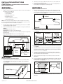
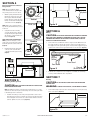
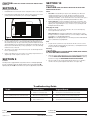
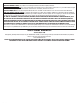
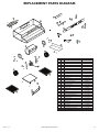
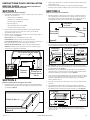
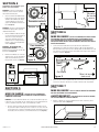
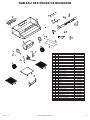
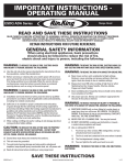
IMPORTANT INSTRUCTIONS OPERATING MANUAL
ESDQ Series
Range Hood
READ AND SAVE THESE INSTRUCTIONS
READ CAREFULLY BEFORE ATTEMPTING TO ASSEMBLE, INSTALL, OPERATE OR MAINTAIN THE PRODUCT DESCRIBED.
PROTECT YOURSELF AND OTHERS BY OBSERVING ALL SAFETY INFORMATION. FAILURE TO COMPLY WITH
INSTRUCTIONS COULD RESULT IN PERSONAL INJURY AND/OR PROPERTY DAMAGE!
RETAIN INSTRUCTIONS FOR FUTURE REFERENCE.
GENERAL SAFETY INFORMATION
When using electrical appliances, basic precautions
should always be followed to reduce the risk of fire,
electric shock and injury to person, including the following:
WARNING: TO REDUCE THE RISK OF FIRE, ELECTRIC SHOCK
AND INJURY TO PERSON, OBSERVE THE FOLLOWING:
WARNING: TO REDUCE THE RISK OF FIRE, ELECTRIC SHOCK, DO
NOT USE THIS FAN WITH ANY SOLID-STATE SPEED CONTROL DEVICE.
a) Use this unit only in the manner intended by the manufacturer.If you
have questions, contact the manufacturer.
b) Before servicing or cleaning the unit, switch power off at service
panel and lock the service disconnecting means to prevent power
from being switched on accidentally. When the service disconnecting means cannot be locked, securely fasten a prominent
warning device, such as a tag, to the service panel.
WARNING: TO REDUCE THE RISK OF A RANGE TOP GREASE FIRE:
WARNING: TO REDUCE THE RISK OF FIRE, ELECTRIC SHOCK
AND INJURY TO PERSON, OBSERVE THE FOLLOWING:
a) Installation work and electrical wiring must be done by qualified
person(s) in accordance with all applicable codes and standards,
including fire-related construction.
b) Sufficient air is needed for proper combustion and exhausting
of gases through the flue (chimney) of fuel burning equipment to
prevent back drafting. Follow the heating equipment manufacturer’s
guideline and safety standards such as those published by the
National Fire Protection Association (NFPA) and the American
Society for Heating, Refrigeration, and Air Conditioning Engineers
(ASHRAE), and the local code authorities.
c) When cutting or drilling into wall or ceiling, do not damage electrical
wiring and other hidden utilities.
CAUTION: TO REDUCE THE RISK OF FIRE AND TO PROPERLY
EXHAUST AIR, BE SURE TO DUCT AIR OUTSIDE - DO NOT VENT
EXHAUST AIR INTO SPACES WITHIN WALLS OR CEILINGS OR INTO
ATTICS, CRAWL SPACES, OR GARAGES.
d) Ducted fans must always be vented to the outdoors.
e) This unit must be grounded.
f) To avoid motor bearing damage and noisy and/or unbalanced
impellers, keep drywall spray, construction dust, etc. off power unit.
g) Read all instructions before installing or using range hood.
a) Never leave surface units unattended at high settings.
Boilovers cause smoking and greasy spillovers that may
ignite. Heat oils slowly on low or medium settings.
b) Always turn hood ON when cooking at high heat or when
flambéing food (ie. Crepes Suzette, Cherries Jubilee,
Peppercorn Beef Flambé).
c) Clean ventilating fans frequently. Grease should not be allowed
to accumulate on fan filter.
d) Use proper pan size. Always use cookware appropriate for
the size of the surface element.
WARNING: TO REDUCE THE RISK OF INJURY TO PERSONS IN
THE EVENT OF A RANGE TOP GREASE FIRE, OBSERVE THE FOLLOWING:
a) SMOTHER FLAMES with a close-fitting lid, cookie sheet, or
metal tray, then turn off burner. BE CAREFUL TO PREVENT
BURNS. If the flames do not go out immediately, EVACUATE
AND CALL THE FIRE DEPARTMENT.
b) NEVER PICK UP A FLAMING PAN - You may be burned.
c) DO NOT USE WATER, including wet dishcloths or towels a violent steam explosion will result.
d) Use an extinguisher ONLY if:
I. You know you have a Class ABC extinguisher, and you
already know how to operate it.
II. The fire is small and contained in the area where it started.
III. The fire department is being called.
IV. You can fight the fire with your back to an exit.
WARNING:
DUCTWORK.
TO REDUCE THE RISK OF FIRE, USE ONLY METAL
SAVE THESE INSTRUCTIONS
5084457 Rev. G 1-11
www.airkinglimited.com
1 of 12
INSTALLATION INSTRUCTIONS
CAUTION:
2. The thickness of the strips should be the same as the recess of the cabinet and
they should be approximately 2" wide.
3. Install the strips using appropriate length wood screws (not included). Make sure
the strips line up to the keyhole slots of the range hood.
SECTION 1
SECTION 3
1. Unpack hood from the carton and confirm that all pieces are present. In addition to
the range hood you should have:
2 - Aluminum Grease Filters
1. Choose the type of ducting you will require. This model is equipped to vent either
Vertically or Horizontally through a 3-1/4" x 10" duct. It can be modified to be ductless (re-circulates the air back into the kitchen) with the addition of 2 models CF-01
Charcoal Filters (not included) (Figure 3).
MAKE SURE POWER IS SWITCHED OFF AT SERVICE PANEL
BEFORE STARTING INSTALLATION.
Prepare the Hood for Installation
Preparing the Range Hood
1 - 3-1/4"x 10" Damper
3 - Damper Mounting Screws
4 - #8 Mounting Screws
1 - GU24 Base, 26W Fluorescent Lamp
1 - Instruction/Safety Sheet
Vertical
Ductless
Horizontal
NOTE: Some hoods may be shipped with a protective plastic adhered to the range
hood. It is recommended to leave this in place during installation to protect the hood
from scratching. Remove when the installation is complete.
2.
Lay the hood flat on a table so the underside is facing you. Use a piece of cardboard
to avoid damaging the table or the hood.
3. Remove the following items from the hood and place in a safe place until needed
(Figure 1):
Grease filters: Pull on tabs to remove.
Bottom cover: Remove the 4 screws holding it in place.
Lamp cover: Squeeze in the sides. The cover is held in place by tension against the
tabs on the hood.
Wire compartment cover: Remove the screw holding it in place.
Blower: Using a 3/8" nut driver or ratchet, remove the 4 nuts holding the blower in place.
Figure 3
2a. Horizontal or Vertical - Remove the apprpriate square knockout by inserting a
screw driver under the edge and break the tabs holding it in place. Peel back with
pliers (Figure 4).
Vertical
Horizontal
Ductless
Lamp Cover
Figure 4
Grease
Filter Tab
2b. Ductless - Lift up and remove the hood’s vent insert located behind the grill, exposing
the front air slots. Do not use a screwdriver or any other object that could scratch the
hood (Figure 4).
Motor
Bottom
Cover
Figure 1
Wire
Compartment
Cover
Determine where the electrical service will enter the hood and remove the appropriate
electrical knockout by inserting a screw driver into the slot and rocking back and forth
until the knockout comes loose (Figure 4).
4.
Once the proper knockout(s) have been removed, either hold the hood up to the
installation location and mark the locations of the ducting, electrical, and mounting
holes or mark the locations by measurement.
5. Cut appropriate holes for ducting connection and electrical connection in the
wall/cabinet.
SECTION 2
6.
Prepare the location for Hood Support
1.
3.
If the hood will be installed under cabinets that have a recessed bottom, it will be
necessary to install wood mounting strips (not included) so the hood will mount
properly (Figure 2).
For 3-1/4" x 10" vertical or horizontal ducting, install the damper assembly to the hood
by sliding the tabbed section of the damper under the hood body and securing with
the two provided screws (Figure 5).
Damper
Hood
Body
Tab
Wood Strip
Figure 5
7.
Install an approved wire connector to the electrical knockout of the hood and guide
the electrical cable through the hood, allowing at least 6" of wire for connections
and tighten.
Figure 2
5084457 Rev. G 1-11
www.airkinglimited.com
2 of 12
SECTION 4
Blower Installation for Ducted
Range Hoods
Horizontal
NOTE: When reinstalling the blower,
ensure that the blower is facing the same
way as how you have chosen to duct it.
1.
With the opening of the blower facing
the direction you have chosen to duct
the hood, place the blower mounting
brackets (brackets on either side of the
blower) over the blower mounting studs
on the interior of the hood (Figure 6).
NOTE: Makes sure to support the blower
in position by hand until it is firmly secured
to the hood.
1/8"
Studs
Vertical
Figure 8
Studs
SECTION 6
2. Using the 4 nuts removed earlier,
secure the blower in place. Start the
nuts by hand first, then tighten with a
3/8" nut driver or ratchet until they are
fully seated (Figure 6).
NOTE: FOR DUCTLESS INSTALLATIONS
ONLY, if you did not already do so in the
earlier steps, remove the vent insert from
behind the grill on the outside of the hood
(Figure 4).
3. Plug the blower into the appropriate
connector on the side of the wire
compartment. It will only fit one way
(Figure 7).
Keyhole
Wiring
CAUTION:
ALL ELECTRICAL CONNECTIONS MUST BE MADE IN ACCORDANCE
WITH LOCAL CODES, ORDINANCES, OR NATIONAL ELECTRICAL CODE. IF YOU ARE
UNFAMILIAR WITH METHODS OF INSTALLING ELECTRICAL WIRING, SECURE THE
SERVICES OF A QUALIFIED ELECTRICIAN.
Ductless
1. Connect the two loose White wire from the range hood to the White wire from
the supply, and the loose Black wire from the range hood to the Black wire of
the supply. Connect the ground wire (green or bare) from the supply to the green
ground screw of the hood. Use approved methods for all connections (Figure 9).
Studs
Figure 6
Neutral
(White)
Hot (Black)
From Hood
From Hood
Figure 9
Connector
Ground
(Green or Bare)
2. Install the wire compartment cover and tighten screw. Make sure all wiring is
securely contained within the wire compartment.
Figure 7
SECTION 7
Ducting
SECTION 5
CAUTION: ALL DUCTING MUST COMPLY WITH LOCAL AND NATIONAL
Installing the Range Hood
CAUTION:
MAKE SURE POWER IS SWITCHED OFF AT SERVICE PANEL
BEFORE STARTING INSTALLATION.
NOTE: If installing into existing construction and you will not have access to the
ductwork once the hood is in place, make ducting connections at this point. Refer
to the Ducting Section for instructions.
BUILDING CODES.
WARNING: TO REDUCE THE RISK OF FIRE, USE ONLY METAL DUCTWORK.
1. Connect the ducting to the hood’s duct collar and damper. Secure in place using
tape to seal all joints (Figure 10).
1. Install the 4 mounting screws at the previously marked locations. Leave
approximately 1/8" clearance. Slide the hood in place through the keyhole
slots and align the front of the hood so that it is flush with the front of the
cabinets. Tighten all screws securely (Figure 8).
Figure 10
5084457 Rev. G 1-11
www.airkinglimited.com
3 of 12
CAUTION:
OR ROOF CAP.
ALWAYS DUCT THE FAN TO THE OUTSIDE THROUGH A WALL
SECTION 10
Maintenance
SECTION 8
CAUTION:
Finishing the Installation
MAKE SURE POWER IS SWITCHED OFF AT SERVICE PANEL
BEFORE SERVICING THE UNIT.
1.
Filters
Reinstall the bottom cover removed in Section 1 using the 4 screws to secure it in place.
2. Reinstall the filters by fitting them into the channel on either side of the hood and
pushing upwards on them until they are secured in place (Figure 11).
1. Grease Filter - Included with your range hood are aluminum grease filters that
should be washed at least once a month. The filters are dishwasher safe and
should be washed in a mild soap or detergent. Reverse the instructions in the
“Finishing the Installation” section of the instructions to remove filters. If the grease
filters become damaged, replace with Air King Model GF-01 Grease Filters.
2. Charcoal Odor Filter - If you have installed the optional charcoal odor filters, they
cannot be washed and must be discarded and replaced when they become noticeably dirty, have stopped filtering the odors, or at least once per year. Replace with
Air King Model CF-01 Odor Filters.
Changing the Lamp
1. Remove the lamp cover by squeezing in the sides. The cover is held in place by
tension against the tabs on the hood.
Figure 11
Channel
3. Install the included 26 watt fluorescent lamp into the lamp holder by lining up the
pins on the lamp base to the socket of the lamp holder and gently turning clockwise until the lamp snaps into place and is firmly seated in the lamp holder. Install
a 4 watt maximum type C7 (candelabra base) night light (not included) into the side
lamp holder and reinstall the lamp cover by squeezing the cover’s sides and fitting
them into the slots on the hood.
4. Turn switches to the “OFF” position and restore power. Test that the light and the
fan are operating properly.
5. If there is any vibration noise, check for the source and try to tighten fasteners or
adjust the tape to make a tighter connection or seal.
SECTION 9
Controls
Your Range Hood is equipped with two rotary switches with one controlling the lighting and
the other controlling the exhaust fan. The light switch has three positions, Main Light ( ● ),
Night Light ( ◗ ), and OFF ( ■ ). The fan switch has four positions, High, Medium, Low, and OFF.
Fluorescent Lamp: Remove lamp by gently twisting counterclockwise to release
the lamp from the base. Installation is the reverse of removal. Replace with Air King
model 26SBL or a compatible 26W GU24 lamp.
Night Light: Unscrew night light bulb from socket and replace with a 4 watt maximum
type C7 (candelabra base) night light bulb.
Fuse
1.
To replace the fuse, turn the fuse cap located next to the wire connector counter
clockwise and pull out. Replace with only a 125-Volt fuse, 1-1/2 Amp Max. Reinstall
the fuse back into the hood (Figure 7).
Cleaning
CAUTION:
DO NOT USE GASOLINE, BENZINE, THINNER, HARSH CLEANSERS,
ETC., AS THEY MAY DAMAGE THE RANGE HOOD.
1. Clean your range hood with a mild detergent, such as dishwashing liquid, and dry with
a soft cloth. NEVER USE ANY ABRASIVE PADS OR SCOURING POWDERS. Completely
dry before restoring power. NEVER IMMERSE ELECTRICAL PARTS IN WATER.
2. The fan assembly can be vacuumed when build up (dirt, lint, etc.) accumulates
over time. The fan is permanently lubricated and does not require oiling.
Troubleshooting Guide
Trouble
Probable Cause
1. Hood does not operate when the switch is on.
1a.
A fuse may be blown or a circuit tripped.
1a. Replace fuse or reset circuit breaker.
Suggested Remedy
1b.
Wiring is not connected properly.
1b. Turn off power to unit. Check that all wires are connected.
2. Hood is operating, but air moves slower than normal.
2.
Obstruction in the exhaust ducting.
2.
Check for any obstructions in the ducting including filter.
3. Hood is making a rattling noise.
3a.
Filters are loose.
3a. Turn off power to unit. Check that all filter are securely in place.
3b.
Duct connection is loose.
3b. Turn off power to unit. Check that duct connection is tight.
Installer:
Installation Date:
Place of Purchase:
Model Number:
5084457 Rev. G 1-11
www.airkinglimited.com
4 of 12
LIMITED WARRANTY
WHAT THIS WARRANTY COVERS: This product is warranted against defects in workmanship and/or materials.
HOW LONG THIS WARRANTY LASTS: This warranty extends only to the original purchaser of the product and lasts for one (1) year from the date of original
purchase or until the original purchaser of the product sells or transfers the product, whichever first occurs.
WHAT AIR KING WILL DO: During the warranty period, Air King will, at its sole option, repair or replace any part or parts that prove to be defective or
replace the whole product with the same or comparable model.
WHAT THIS WARRANTY DOES NOT COVER: This warranty does not apply if the product was damaged or failed because of accident, improper handling or
operation, shipping damage, abuse, misuse, unauthorized repairs made or attempted. This warranty does not cover shipping costs for the return of products
to Air King for repair or replacement. Air King will pay return shipping charges from Air King following warranty repairs or replacement
ANY AND ALL WARRANTIES, EXPRESSED OR IMPLIED (INCLUDING, WITHOUT LIMITATION, ANY IMPLIED WARRANTY OF MERCHANTABILITY), LAST
ONE YEAR FROM THE DATE OF ORIGINAL PURCHASE OR UNTIL THE ORIGINAL PURCHASER OF THE PRODUCT SELLS OR TRANSFERS THE PRODUCT,
WHICHEVER FIRST OCCURS AND IN NO EVENT SHALL AIR KING’S LIABILITY UNDER ANY EXPRESS OR IMPLIED WARRANTY INCLUDE (I) INCIDENTAL OR
CONSEQUENTIAL DAMAGES FROM ANY CAUSE WHATSOEVER, OR (II) REPLACMENT OR REPAIR OF ANY HOUSE FUSES, CIRCUIT BREAKERS OR RECEPTACLES.
NOTWITHSTANDING ANYTHING TO THE CONTRARY, IN NO EVENT SHALL AIR KING’S LIABILITY UNDER ANY EXPRESS OR IMPLIED WARRANTY EXCEED
THE PURCHASE PRICE OF THE PRODUCT AND ANY SUCH LIABILITY SHALL TERMINATE UPON THE EXPIRATION OF THE WARRANTY PERIOD.
Some states and provinces do not allow limitations on how long an implied warranty lasts, or the exclusion or limitation of incidental or consequential damages,
so these exclusions or limitations may not apply to you. This warranty gives you specific legal rights. You may also have other rights which vary from state to
state and province to province. Proof of purchase is required before a warranty claim will be accepted.
CUSTOMER SERVICE:
Toll-Free (800) 465-7300
Our Customer Service team is available to assist you with product questions, service center locations, and replacement parts. They can be reached Monday
through Friday, 8am-4pm Eastern. Please have your model number available, as well as the type and style (located on the label inside of your product).
Please do not return product to place of purchase.
www.airkinglimited.com
PARTS FOR DISCONTINUED, OBSOLETE AND CERTAIN OTHER PRODUCTS MAY NOT BE AVAILABLE. DUE TO SAFETY REASONS, MANY ELECTRONIC
COMPONENTS AND MOST HEATER COMPONENTS ARE NOT AVAILABLE TO CONSUMERS FOR INSTALLATION OR REPLACEMENT.
5084457 Rev. G 1-11
www.airkinglimited.com
5 of 12
REPLACEMENT PARTS DIAGRAM
8
5
1
7
2
4
30
29
27
28
3
9
6
13
10
14
12
22
15
16
21
19
11
18
18
17
19
20
18
17
23
24
25
23
5084457 Rev. G 1-11
26
31
# Qty.
1 2
2 1
3 1
4 1
5 1
6 1
7 1
8 1
9 2
10 1
11 4
12 1
13 1
14 6
15 2
16 1
17 1
18 4
19 2
20 1
21 1
22 1
23 2
24 1
25 4
26 1
27 1
28 1
29 1
30 1
31 1
www.airkinglimited.com
Description
#8 B Screw
Damper
Damper Frame
Wrapper
Vent Cover
Grill
Light Switch
Motor Switch
Knob
Lamp Holder
#6 B Screw
Light Harness
Capacitor Harness
#6 x 3/8 Type A Screw
Air Inlet Collar
Blower Housing
Twin Blower Wheel L
#8-32 Screw
Motor Mounting Bracket
Motor
Twin Blower Wheel R
Wire Compartment Cover
Grease Filter (GF-01)
Bottom Cover
#6 A Screw
Lamp Cover
Fuse
Fuse Holder
Lead Wire in Fuse Holder
Lead Wire Out Fuse Holder
Lamp
Replacement Part #
5S1999015
5S1999014
5S1199013
5S1111014
5S1111040
5S1111043
5S1136071
5S1136070
5S1111046
5S1111016
5S1999017
5S1111052
5S1111019
5S1999113
5S1111023
5S1111024
5S1111025
5S1999003
5S1111027
5S1111028
5S1111029
5S1111048
5S1111033
5S1111032
5S1999113
5S1111053
5S1111054
5S1199205
5S1111055
5S1111056
5S9999010
6 of 12
INSTRUCCIONES IMPORTANTES –
MANUAL DE OPERACIÓN
ESDQ Series
Hotte de cuisinière
LIRE ET CONSERVER CES INSTRUCTIONS
LIRE SOIGNEUSEMENT AVANT DE TENTER D’ASSEMBLER, INSTALLER, OPÉRER OU DE RÉPARER LE PRODUIT DÉCRIT.
PROTÉGEZ VOUS-MÊME ET LES AUTRES EN OBSERVANT TOUTE L’INFORMATION DE SÉCURITÉ. FAILLIR À SE CONFORMER
AUX INSTRUCTIONS PEUT RÉSULTER EN BLESSURE PERSONNELLE GRAVE ET/OU EN DOMMAGE À LA PROPRIÉTÉ.
CONSERVER CES INSTRUCTIONS POUR RÉFÉRENCES FUTURES.
INSTRUCTIONS GÉNÉRALES DE SÉCURITÉ
Lors de l’utilisation d’appareils électriques, des précautions de base doivent
toujours être suivies pour réduire les risques d’incendie, de choc
électrique et de blessures corporelles, incluant ce qui suit:
AVERTISSEMENT: POUR RÉDUIRE LES RISQUES
D’INCENDIE, DE CHOC ÉLECTRIQUE OU DE BLESSURES PERSONNELLES
OBSERVER CE QUI SUIT:
a) Utiliser cette unité seulement de la manière pour laquelle le fabricant
l’a conçu. Si vous aviez des questions, veuillez contacter le fabricant.
b) Avant d’effectuer un service ou de nettoyer l’unité, couper
l’alimentation électrique dans le panneau de distribution
et verrouiller le dispositif de déconnexion afin d’éviter que
l’alimentation ne revienne accidentellement. Lorsque le dispositif
ne peut être verrouillé, fixer solidement un avis d’avertissement,
tel qu’une étiquette, au panneau de distribution.
AVERTISSEMENT: POUR RÉDUIRE LES RISQUES
D’INCENDIE, DE CHOC ÉLECTRIQUE OU DE BLESSURES PERSONNELLES
OBSERVER CE QUI SUIT:
a) Le travail d’installation et le câblage électrique doivent être effectués
par une(des) personne(s) qualifiée(s) en conformité avec tous les codes
et normes applicables, incluant la construction relative aux incendies.
b) De l’air en quantité suffisante est requis pour la bonne combustion
et l’évacuation de gaz par le conduit (cheminée) provenant
d’équipement de brûlage au combustible pour prévenir un
refoulement. Suivre les directives du fabricant de l’équipement de
chauffage et les normes de sécurité telles que celles publiées par
la National Fire Protection Association (NFPA) et de la American
Society for Heating, Refrigeration, and Air Conditioning Engineers
(ASHRAE), et de celles des autorités locales du code.
c) Lorsque vous coupez ou perforez un mur ou un plafond, prenez
garde de ne pas endommager les fils électriques ou tout appareil
qui pourrait être dissimulé.
AVERTISSEMENT: POUR RÉDUIRE LES RISQUES D’INCENDIE
ET POUR ÉVACUER L’AIR ADÉQUATEMENT, ASSUREZ-VOUS D’ÉVACUER
L’AIR VERS L’EXTÉRIEUR – NE PAS ÉVACUER L’AIR DANS DES ESPACES
DANS LES MURS, LES PLAFONDS OU LES GRENIERS, LES GALERIES
TECHNIQUES OU LES GARAGES.
d) Les ventilateurs avec conduits doivent toujours être évacués vers
l’extérieur.
e) Cette unité doit être mise à la terre.
f) Pour éviter des dommages aux roulements des moteurs et/ou des
hélices bruyantes ou déséquilibrées, empêcher la poussière de
cloison sèche, poussière de construction, etc., d’atteindre l’unité
de puissance.
g) Lire toutes les instructions avant d’installer ou d’utiliser la hotte
de cuisine.
5084457 Rev. G 1-11
AVERTISSEMENT: POUR RÉDUIRE LES RISQUES D’INCENDIE
OU DE CHOC ÉLECTRIQUE, NE PAS UTILISER CE VENTILATEUR AVEC UN
RÉGULATEUR DE VITESSE ÉLECTRONIQUE.
AVERTISSEMENT: POUR RÉDUIRE LES RISQUES
D’INCENDIE DE GRAISSE SUR LE DESSUS DE LA CUISINIÈRE:
a) Ne jamais laisser les unités de surface à des degrés élevés
sans surveillance. Les débordements par bouillonnement
produisent de la fumée et des débordements graisseux qui
peuvent s’enflammer. Chauffer les huiles lentement à des
degrés faibles ou modérés.
b) Toujours mettre la hotte EN MARCHE lors de cuisson à haute
température ou lors de flambage de nourriture (par ex., des
Crêpes Suzette, de Cerises Jubilées, steak flambé, etc.)
c) Nettoyer les ventilateurs d’évacuation fréquemment. Aucune
accumulation de graisse ne devrait être tolérée sur les filtres
du ventilateur.
d) Utiliser des poêlons de taille appropriée. Toujours utiliser les batteries de cuisine appropriées pour la taille de l’élément de surface.
AVERTISSEMENT: POUR RÉDUIRE LES RISQUES DE BLES-
SURES PERSONNELLES DANS L’ÉVENTUALITÉ D’UN FEU DE GRAISSE
SUR LA SURFACE DE CUISSON, SUIVRE LES INDICATIONS SUIVANTES:
a) ÉTOUFFER LES FLAMMES avec un couvercle bien ajusté, une
tôle à biscuits, ou un cabaret de métal, puis, mettre le gril
hors fonction. PRENEZ SOIN D’ÉVITER LES BRÛLURES. Si
les flammes ne s’éteignent pas immédiatement, ÉVACUER ET
APPELER LE SERVICE DES INCENDIES.
b) NE JAMAIS SAISIR UN POÊLON EN FLAMME – vous pourriez
être brûlé.
c) NE PAS UTILISER DE L’EAU, incluant les linges à vaisselle
ou les serviettes mouillées – il en résulterait une violente
explosion de vapeur.
d) Utiliser un extincteur SEULEMENT SI:
I. Vous savez que vous avez un extincteur de classe ABC,
et que vous savez déjà comment l’opérer.
II. Le feu est petit et contenu dans la zone où il a commencé.
III. On appelle le service des incendies.
IV. Vous pouvez combattre l’incendie avec une sortie
derrière vous.
AVERTISSEMENT: POUR RÉDUIRE LES RISQUES
D’INCENDIE, UTILISER UNIQUEMENT DES CONDUITS EN MÉTAL.
CONSERVER CES INSTRUCTIONS
www.airkinglimited.com
7 of 12
INSTRUCTIONS POUR L’INSTALLATION
2. L’épaisseur des bandes doit correspondre au retrait de l'armoire et doit avoir une
largeur d'environ 5 cm.
MISE EN GARDE : MAKE SURE POWER IS SWITCHED OFF AT
3.
SECTION 1
SECTION 3
2 - Filtres à graisses en aluminium
1 - Adaptateur de conduit de 8,25 cm x 25,4 cm
1. Déterminez le type de conduits dont vous aurez besoin. Ce modèle peut évacuer
l’air verticalement ou horizontalement par un conduit de 8,25 cm sur 25,4 cm. On
peut également l’utiliser sans évacuation (il rejette alors l’air dans la cuisine) en
ajoutant 2 filtres au charbon de modèle CF-01 (non compris) (Figure 3).
3 - Vis de montage de l’adaptateur
4 - Vis de montage no 8
1 - Base GU24, lampe fluorescente de 26W
1 - Instructions et mesures de sécurité
SERVICE PANEL BEFORE STARTING INSTALLATION.
Préparation de la hotte de cuisinière
1. Sortez la hotte de l’emballage et assurez-vous d’avoir toutes les pièces. En plus
de la hotte, vous devriez avoir :
Préparez la hotte pour l’installation
Évacuation
verticale
2. Déposez la hotte à plat sur la table de manière à ce que la partie inférieure
soit face à vous. Placez un morceau de carton en dessous afin d’éviter
d’endommager la table ou la hotte.
Filtres à graisses : tirez sur les languettes pour les retirer.
Panneau inférieur : retirez les 4 vis qui le maintiennent en place.
Écran protecteur de lampe : appuyez sur les côtés. Le panneau est maintenu en
place grâce à la pression exercée sur les languettes de la hotte.
Couvercle du compartiment des fils : retirez la vis qui le maintient en place.
Ventilateur : à l’aide d’un tournevis à douille ou d’une clé à cliquet de 3/8 po,
retirez les 4 écrous qui tiennent le ventilateur.
Figure 3
2a. Évacuation horizontale ou verticale - Retirez la pièce rectangulaire défonçable.
Pour ce faire, insérez un tournevis dans le pourtour et brisez les attaches qui le
retiennent. Enlevez ensuite la pièce avec des pinces (Figure 4).
Évacuation
verticale
Écran protecteur de lampe
Figure 1
Sans évacuation
2b. Sans évacuation - Soulevez et retirez le panneau de l’évent situé derrière la grille,
exposant ainsi l’entrée d’air frontale. N’utilisez pas de tournevis ni tout autre objet qui
pourrait égratigner la hotte (Figure 4).
Couvercle du
compartiment
des fils
SECTION 2
3.
Déterminez par où les fils entreront dans la hotte et retirez l’entrée électrique défonçable appropriée. Pour ce faire, insérez un tournevis dans la fente et faites un mouvement de va-et-vient jusqu’à ce que la pièce se détache (Figure 4).
4.
Une fois que l’entrée défonçable appropriée a été enlevée, tenez la hotte à l'endroit
où elle sera fixée et marquez l'emplacement des trous pour les conduits, les entrées
électriques et l'installation. Sinon, vous pouvez prendre les mesures et faire les
marques à partir de celles-ci.
5. Percez des trous dans le mur ou l'armoire pour le raccord de conduit et l'entrée
électrique.
Préparez l’emplacement du support de la hotte.
1.
Évacuation
horizontale
Figure 4
Moteur
Panneau
inférieur
Sans
évacuation
Évacuation
horizontale
3. Retirez les pièces suivantes de la hotte et placez-les à un endroit sûr jusqu’à ce
que vous en ayez besoin (Figure 1) :
Languette
du filtre à
graisses
Posez les bandes à l’aide de vis à bois (non comprises) de longueur appropriée.
Assurez-vous que les bandes sont alignées aux encoches en trou de serrure de la hotte.
Pour installer la hotte sous des armoires dont la base est en retrait, il faut d’abord
installer des bandes de fixation en bois (non comprises) afin que la hotte soit fixée
convenablement (Figure 2).
6.
Si vous installez le conduit de 8,25 cm sur 25,4 cm horizontal ou vertical, fixez
l’adaptateur à la hotte. Pour ce faire, insérez la bordure de la hotte dans la rainure
de l’adaptateur et fixez ce dernier avec les deux vis prévues à cet effet (Figure 5).
Adaptateur
Hotte
Bande de bois
Languette
Figure 5
Figure 2
5084457 Rev. G 1-11
7. Passez le câble par l'entrée électrique en prenant soin de garder un jeu de
15,24 cm pour les raccords, puis fixez le capuchon de connexion homologué au
câble en le vissant.
www.airkinglimited.com
8 of 12
SECTION 4
Installation du ventilateur pour
hottes avec évacuation
Évacuation horizontale
REMARQUE : lorsque vous réinstallez le
ventilateur, assurez-vous de le remettre
exactement à la même place.
1.
Une fois l’ouverture du ventilateur dans
la direction choisie, placez les supports
de fixation du ventilateur (de chaque
côté du ventilateur) au-dessus des
goujons du ventilateur à l’intérieur de
la hotte (Figure 6).
REMARQUE : Assurez-vous de bien maintenir
le ventilateur en place jusqu'à ce qu'il soit
solidement fixé à la hotte.
2.
Fixez le ventilateur à l’aide des 4 vis que
vous avez enlevées plus tôt. Commencez
à visser les écrous à la main, puis
serrez-les à l'aide d’un tournevis à
douille ou d’une clé à cliquet de 3/8 po
jusqu’à ce qu'ils soient complètement
enfoncés (Figure 6).
REMARQUE : INSTALLATION SANS
ÉVACUATION SEULEMENT, Si ce n’est
déjà fait, retirez le panneau de l’évent situé
derrière la grille (Figure 4).
3. Branchez le ventilateur au connecteur
approprié sur le côté du compartiment
de fils. Le branchement ne pourra se
faire que dans un seul sens (Figure 7).
0,32 cm
Encoche
en trou de
serrure
Goujons
Évacuation verticale
Figure 8
Goujons
SECTION 6
Câblage
MISE EN GARDE :
Sans évacuation
TOUTES LES CONNEXIONS ÉLECTRIQUES DOIVENT
ÊTRE CONFORMES AUX CODES DU BÂTIMENT LOCAUX, AUX RÈGLEMENTS LOCAUX
OU AU CODE NATIONAL DE L'ÉLECTRICITÉ. SI LES MÉTHODES POUR INSTALLER DES
CÂBLAGES ÉLECTRIQUES NE VOUS SONT PAS FAMILIÈRES, FAITES APPEL AUX SERVICES
D’UN ÉLECTRICIEN QUALIFIÉ.
1. Connectez les deux câbles blancs lâches de la hotte au câble blanc de
l’alimentation, et le câble noir lâche de la hotte au câble noir de l'alimentation.
Branchez le fil de mise à la terre (vert ou dénudé) du bloc d’alimentation à la vis de
mise à la terre verte de la hotte. Suivez les méthodes homologuées pour effectuer
toutes les connexions (Figure 9).
Goujons
Figure 6
Neutre
(blanc)
Chaud (noir)
De la hotte
De la hotte
Figure 9
Connector
Mise à la terre
(vert ou nu)
2. Placez le couvercle du compartiment de fils et serrez la vis. Assurez-vous que
tous les fils sont placés de manière sécuritaire à l’intérieur du compartiment.
Figure 7
SECTION 7
SECTION 5
Conduits
Installation de la hotte
MISE EN GARDE :
MISE EN GARDE : ASSUREZ-VOUS QUE L’ALIMENTATION
ÉLECTRIQUE EST COUPÉE À PARTIR DU PANNEAU DE DISTRIBUTION AVANT DE
COMMENCER L’INSTALLATION.
REMARQUE : si vous installez la hotte dans une construction existante et que vous
n'aurez plus accès aux conduits une fois la hotte fixée, posez-les maintenant. Pour
ce faire, consultez les instructions de la section traitant des conduits.
TOUS LES CONDUITS DOIVENT ÊTRE CONFORMES
AUX CODES DU BÂTIMENT LOCAUX ET NATIONAUX.
AVERTISSEMENT :
AFIN DE RÉDUIRE LES RISQUES D’INCENDIE,
UTILISEZ UNIQUEMENT DES CONDUITS EN MÉTAL.
1. Reliez le conduit au raccord et à l’adaptateur de la hotte. Scellez les joints à
l’aide d’un ruban adhésif (Figure 10).
1. Vissez les 4 vis de montage aux endroits préalablement marqués. Laissez
un jeu d’environ 0,32 cm. Faites glisser les vis dans les encoches en trou de
serrure de la hotte, en prenant soin d’aligner la partie avant de la hotte avec
le rebord des armoires. Ensuite, serrez fermement toutes les vis (Figure 8).
Figure 10
5084457 Rev. G 1-11
www.airkinglimited.com
9 of 12
MISE EN GARDE :
DIRIGEZ TOUJOURS LES CONDUITS DU
VENTILATEUR VERS L’EXTÉRIEUR EN VOUS ASSURANT QUE L’EXTRÉMITÉ EST
MUNIE D’UN CAPUCHON DE MUR OU DE TOIT.
SECTION 10
Entretien
MISE EN GARDE :
SECTION 8
ASSUREZ-VOUS QUE L’ALIMENTATION
ÉLECTRIQUE EST COUPÉE À PARTIR DU PANNEAU DE DISTRIBUTION AVANT DE
PROCÉDER À L’ENTRETIEN DE L’APPAREIL.
Fin de l’installation
1.
Réinstallez le panneau inférieur que vous avez retiré à la Section 1 en le fixant à l’aide
des 4 vis.
2.
Réinstallez les filtres en les glissant dans les rainures, de chaque côté de la hotte, et en
les poussant vers le haut jusqu’à ce qu’ils soient bien en place (Figure 11).
Filtres
1.
Filtre à graisses - Des filtres à graisses en aluminium, que vous devez nettoyer au
moins une fois par mois, sont inclus avec la hotte. Ceux-ci vont au lave-vaisselle et
doivent être lavés avec un savon ou un détergent doux. Pour retirer les filtres, suivez les
instructions de la section « Fin de l’installation » en commençant par la fin. Remplacez
les filtres à graisses endommagés par des filtres Air King de modèle GF-01.
2. Filtre à odeurs au charbon - Les filtres à odeurs au charbon (optionnels) ne peuvent
être nettoyés. S’ils deviennent trop sales et ne filtrent plus les odeurs ou qu’ils ont un
an d’usure, vous devez les jeter et vous en procurer des nouveaux. Remplacez-les
par les filtres à odeurs Air King de modèle CF-01.
Changement de la lampe
1. Retirez l’écran protecteur de lampe en appuyant sur les côtés. Le panneau est
maintenu en place grâce à la pression exercée sur les languettes de la hotte.
Ampoule fluorescente : Retirez la lampe en tournant attentivement dans le sens
contraire des aiguilles d’une montre pour libérer la lampe de la base. L'installation
est l'inverse de la dépose. L'installation est l'inverse du démontage. Remplacez par
le modèle 26SBL de Air King ou une lampe compatible de 26W GU24.
3. Installez la lampe fluorescente de 26 watts incluse dans la douille en alignant les
broches de la base de la lampe à la prise de la douille et le tournant doucement
dans le sens des aiguilles d’une montre jusqu'à ce que la lampe se mette en
place et soit bien installée dans la douille de lampe. Installez une lampe veilleuse
(non comprise) de type C7 (à petit culot) d'un maximum de 4 watts dans la douille
latérale, puis réinstallez l’écran protecteur de lampe. Pour ce faire, serrez les
côtés de l’écran et insérez-les dans les encoches de la hotte.
Lampe veilleuse : dévissez l’ampoule de la veilleuse de la douille et remplacez-la par
une ampoule de veilleuse de type C7 (à petit culot) d'un maximum de 4 watts.
4. Mettez les deux interrupteurs en position « arrêt », puis rétablissez l’alimentation
électrique. Vérifiez si la lumière et le ventilateur fonctionnent correctement.
Nettoyage
Figure 11
Rainure
5. Si vous entendez un bruit de vibration, cherchez-en la source et essayez de
resserrer les fixations. Sinon, vous pouvez ajuster le ruban adhésif afin de
resserrer ou de sceller le point de connexion.
SECTION 9
Commandes
Votre hotte est munie de deux interrupteurs rotatifs dont un règle l’éclairage et l’autre le
ventilateur d’évacuation. L’interrupteur de la lampe a trois positions : lampe principale ( ●
), lampe veilleuse ( ◗ ), et arrêt ( ■ ). L'interrupteur du ventilateur a quatre positions, élevé,
moyen, faible, et arrêt.
Fusible
1.
Pour remplacer la fusible, tournez vers la droite le dessus de la fusible localisée
à coté du fil conducteur et tirez. Remplacez avec une fusible de 125 volts, 1-1/2
ampères max. Remettez la fusible dans son emplacement (Figure 7).
MISE EN GARDE : N’UTILISEZ PAS D’ESSENCE, DE BENZINE, DE
DILUANT, DE PRODUITS D’ENTRETIEN PUISSANTS, ETC., PUISQU’ILS POURRAIENT
ENDOMMAGER LA HOTTE.
1. Nettoyez la hotte avec du savon doux, comme du savon à vaisselle liquide, et un
chiffon doux et sec. N'UTILISEZ JAMAIS DE TAMPON ABRASIF OU DE POUDRE
À RÉCURER. Essuyez complètement l’appareil avant de rétablir l’alimentation
électrique. N’IMMERGEZ JAMAIS DE COMPOSANTS ÉLECTRIQUES DANS L’EAU.
2. Vous pouvez nettoyer les dépôts (saletés, peluches, etc.) qui se sont accumulés
dans le ventilateur à l’aide d’un aspirateur. Comme le ventilateur est continuellement lubrifié, il n’est pas nécessaire de l’huiler.
Guide de dépannage
Trouble
Cause possible
Solution suggérée
1. La hotte ne fonctionne pas lorsque l’interrupteur 1a. Un fusible peut être grillé ou un disjoncteur peut
1a.
est à EN (ON).
être déclenché.
1b. Le câblage n’est pas raccordé correctement.
1b.
2. La hotte fonctionne, mais l’air circule plus
2. Obstruction dans les conduits d’évacuation.
2.
lentement que la normale.
3. La hotte produit un son de crécelle.
3a. Le moteur est lâche.
3a.
3b. Le raccord des conduits est lâche.
3b.
Remplacer le fusible ou réinitialiser le disjoncteur.
Couper l’alimentation de l’unité. Vérifier que tous les fils sont raccordés.
Vérifier pour quelque obstruction dans les conduits incluant le filtre.
Couper l’alimentation de l’unité. Retirer le filtre, vérifier que toutes les
vis sont serrées complètement.
Couper l’alimentation de l’unité. Vérifier que tous les raccords des
conduits sont bien serrés.
Installateur :
Date d’installation :
Lieu de l’achat :
Numéro de modèle :
5084457 Rev. G 1-11
www.airkinglimited.com
10 of 12
GARANTIE LIMITÉE
CE QUE COUVRE CETTE GARANTIE : Ce produit est garanti contre tout vice de fabrication ou de matière.
COMBIEN DE TEMPS CETTE GARANTIE DURE : Cette garantie se rapporte seulement à l'acheteur original du produit et dure pendant une (1) année de la
date de l'achat original ou jusqu'à ce que l'acheteur original du produit vend ou transfère le produit, celui qui se produit en premier.
QUE FERA AIR KING : Au cours de la période de garantie, Air King, à son choix, réparera ou remplacera n'importe quelle partie ou pièces qui s'avèrent
défectueuses ou remplacera le produit entier par le même modèle ou un modèle comparable.
CE QUE CETTE GARANTIE NE COUVRE PAS : Cette garantie ne s'applique pas si le produit était endommagé ou arrête de fonctionner en raison d’un accident,
d’une mauvaise manipulation ou opération, de dommages d’expédition, d’abus, de mauvaise utilisation, de réparation faite ou tentées non autorisées. Cette
garantie ne couvre pas les coûts d'expédition pour le retour des produits à Air King pour la réparation ou le remplacement. Air King payera les frais d'expédition
de retour de Air King après les réparations ou le remplacement de garantie.
TOUTES LES GARANTIES, EXPRESSES OU TACITES (COMPRENANT, SANS LIMITATION, TOUTE GARANTIE TACITE DE VALEUR MARCHANDE), DURENT UN
AN DE LA DATE DE L'ACHAT ORIGINAL OU JUSQU'À CE QUE L'ACHETEUR ORIGINAL DU PRODUIT VEND OU TRANSFÈRE LE PRODUIT, CELUI QUI SE PRODUIT
EN PREMIER ET DANS AUCUN CAS AIR KING N’ASSUME AUCUNE RESPONSABILITÉ EXPRESSE OU TACITE POUR (I) DES DOMMAGES ACCIDENTELS OU
INDIRECTS DE N’IMPORTE QUELLE CAUSE, OU (II) LE REPLACEMENT OU LA RÉPARATION DE TOUS FUSIBLES, DISJONCTEURS OU RÉCEPTACLES DE MAISON.
MALGRÉ N'IMPORTE QUOI À L'EFFET CONTRAIRE, DANS AUCUN CAS LA RESPONSABILITÉ D’AIR KING, SOUS UNE GARANTIE EXPRESSE OU TACITE, NE
DÉPASSERA LE PRIX D'ACHAT DU PRODUIT ET UNE TELLE RESPONSABILITÉ SE TERMINERA AVEC L'EXPIRATION DE LA PÉRIODE DE GARANTIE.
Certains états et provinces ne permettent pas les limitations de la période de garantie, ou l'exclusion ou la restriction des dommages accidentels ou indirects,
et, par conséquent, les présentes restrictions ne peuvent pas s’appliquer. La présente garantie vous donne des droits légaux spécifiques et peut-être certains
autres droits qui peuvent varier selon la province. La preuve d’achat est exigée avant qu'une réclamation de garantie ne soit acceptée.
SERVICE À LA CLIENTÈLE :
Sans frais (800) 465-7300
Notre équipe de service à la clientèle est disponible pour vous aider avec des questions sur le produit, les adresses des centres de service, et les pièces de
rechange. Vous pouvez la rejoindre, du lundi au vendredi, de 8h:00 à 16h:00 HNE. Veuillez avoir le numéro du modèle disponible, ainsi que le genre et le style
(qui se trouvent sur l'étiquette à l'intérieur de votre produit).
Veuillez ne pas renvoyer le produit à l'endroit de l'achat.
www.airkinglimited.com
IL SE PEUT QUE LES PIÈCES POUR LES PRODUITS DISCONTINUÉS, OBSOLÈTES ET AUTRES PRODUITS NE SOIENT PAS DISPONIBLES. POUR DES RAISONS
DE SÛRETÉ, BEAUCOUP DE COMPOSANTS ÉLECTRONIQUES ET LA PLUPART DES COMPOSANTS DES CHAUFFAGES NE SONT PAS À LA DISPOSITION DES
CONSOMMATEURS POUR L'INSTALLATION OU LE REMPLACEMENT.
5084457 Rev. G 1-11
www.airkinglimited.com
11 of 12
TABLEAU DES PIÈCES DE RECHANGE
8
5
1
7
2
4
30
29
27
28
3
9
6
13
10
14
12
22
15
16
21
19
11
18
18
17
19
20
18
17
23
24
25
23
5084457 Rev. G 1-11
26
31
n° Qte.
1 2
2 1
3 1
4 1
5 1
6 1
7 1
8 1
9 2
10 1
11 4
12 1
13 1
14 6
15 2
16 1
17 1
18 4
19 2
20 1
21 1
22 1
23 2
24 1
25 4
26 1
27 1
28 1
29 1
30 1
31 1
www.airkinglimited.com
Description
Pièces de rechange n°
Vis B n° 8
5S1999015
Adaptateur
5S1999014
Cadre d’adaptateur
5S1199013
Hotte
5S1111014
Panneau de l’évent
5S1111040
Grille
5S1111043
Interrupteur de la lampe
5S1136071
Interrupteur du moteur
5S1136070
Bouton
5S1111046
Douille
5S1111016
Vis B n° 6
5S1999017
Câble de la lumière
5S1111052
Câble du condensateur
5S1111019
Vis n° 6 x 3/8 A
5S1999113
Bague d’entrée d’air
5S1111023
Boîtier du ventilateur
5S1111024
Roue du ventilateur double (gauche)
5S1111025
Vis n° 8-32
5S1999003
Support du moteur
5S1111027
Moteur
5S1111028
Roue du ventilateur double (droite)
5S1111029
Couvercle du compartiment des fils
5S1111048
Filtre à graisses (GF-01)
5S1111033
Panneau inférieur 5S1111032
Vis A n° 6
5S1999113
Écran protecteur de lampe 5S1111053
Fusible
5S1111054
Socle à Fusible
5S1199205
Fil conducteur interne
5S1111055
Fil conducteur externe
5S1111056
Lampe
5S9999010
12 of 12