1
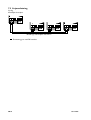
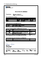
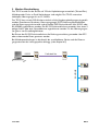
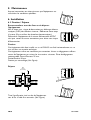
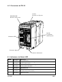
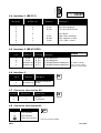
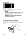
INSTALLATIONSANVISNING
INSTALLATION MANUAL
INSTALLATIONS ANLEITUNG
MANUEL D’INSTALLATION
6611-2001
Galvanic
Isolation
Transient
Protection
Balanced
Transmission
Multidropp 2-tråd
Multidrop 2-wire
Multidrop 2-Draht
Multipoints 2-fils
www.westermo.com
CE
Approved
© Westermo Teleindustri AB • 2002 • REV. C
DC
/
C
A
9
TD-2
em
d
o
m
FSK
Innehållsförteckning
1. Säkerhet
..........................................................................................................................................................................
2. Godkännanden
.......................................................................................................................................................
2.1 Tillverkningsdeklaration (Declaration of conformity) .............................................................
3. Introduktion
..............................................................................................................................................................
3
4
5
6–7
Anslutningar ............................................................................................................................................................. 6
Isolation mellan gränssnitten ...................................................................................................................... 6
Temperaturområde ............................................................................................................................................ 6
Mekanik ........................................................................................................................................................................ 7
Räckvidd och signaldämpning ..................................................................................................................... 7
Vändtider .................................................................................................................................................................... 7
4. Specifikationer
4.1
4.2
4.3
4.4
4.5
4.6
3
5. Underhåll
................................................................................................................................................
.......................................................................................................................................................................
8
8–12
6.1 Montering/Demontering ................................................................................................................................. 8
6.2 Anslutningar ............................................................................................................................................................. 9
6.3 Lysdiodsindikeringar ........................................................................................................................................... 9
6.4 Gränssnitt 1 (RS-232) .................................................................................................................................... 10
6.5 Gränssnitt 2 (RS-422/485) .......................................................................................................................... 10
6.6 Gränssnitt 3 ........................................................................................................................................................... 10
6.7 Matning DC anslutning ................................................................................................................................. 10
6.8 Matning AC anslutning .................................................................................................................................. 10
6.9 Inställning ...................................................................................................................................................... 11–12
6.9.1 Switchinställningar ...................................................................................................................... 11–12
6. Installation
........................................................................................................................................................
13–14
Blockdiagram ....................................................................................................................................................... 13
RS-422/485 anslutning ................................................................................................................................... 13
Linjeanslutning .................................................................................................................................................... 14
7. Funktionell beskrivning
7.1
7.2
7.3
SE.2
................................................................................................................
6611-2001
1. Säkerhet
!
!
!
Allmänt:
Innan enheten används, läs denna manual fullständigt och jämför med uppgifter på
enheten, samt säkerställ att du har förstått all information. Kontrollera att användandet av enheten i din installation inte kommer att överskrida specificerade
säkerhetsprestanda för enheten.
Före installations-, underhålls- eller modifieringsarbete:
Potentialutjämna dig till en jordnings punkt (tex. genom att använda handledsband),
så att skada av intern elektronik på grund av elektrostatiska urladdningar (ESD)
förhindras.
Koppla ifrån enheten från AC/DC matningsnät samt alla andra elektriska
anslutningar, så att åtkomst till farliga spänningar förhindras.
Installation:
Enheten är konstruerad för användning i professionella system. Enheten skall
installeras i utrymmen med begränsad åtkomst, t ex låsbart skåp med tillträde
endast för service personal.
Enheten är konstruerad för fast anslutning till AC/DC matningsnät och skall
installeras av behörig personal.
Enhetens anslutning till matningsnätet skall vara tillräckligt avsäkrat, och om så
krävs skall det vara möjligt att manuellt koppla från enheten från matningsnätet.
Observera att nationella installations regler skall följas.
Enhet med märkspänning överskridande 42,4 V topp eller 60 V DC, är en klass I
utrustning som skall skyddsjordas.
Enhet med märkspänning upp till 42,4 V topp eller 60 V DC, är en klass III utrustning som skall vara separerad från farliga spänningar med dubbel eller förstärkt
isolation.
Enheten kyls genom konvektion. Följ föreskrivna monterings rekommendationer
för att förhindra störningar i kylande luftström kring enheten (se Installation).
TD-29 är avsedd att användas på dedikerade linjer och får ej kopplas in på
allmänna eller hyrda telelinjer. Ej kodkänd enligt Europeisk standard CTR-15.
2. Godkännanden
Uppfyllande av direktiv 73/23/EEC (lågspännings direktivet) har säkerställt genom
tillämpning av standard EN60950.
Uppfyllande av direktiv 89/339/EEC (elektromagnetisk kompabilitet) har säkerställts
genom tillämpning av standard EN61000-6-2 (immunitet i industrimiljö) och standard
EN61000-6-3 (emission från utrustning i bostäder, kontor och liknande miljö).
6611-2001
SE.3
2.1 Tillverkningsdeklaration (Declaration of conformity)
SE.4
6611-2001
3. Introduktion
TD-29 är konstruerad för kommunikation på 2-tråds partvinnad kopparkabel. Multidropp
och punkt till punkt förbindelser med halvduplex är möjliga.TD-29 klarar halv duplex
med 19.2 kbit/s som maximal överföringshastighet.
TD-29 kan ställas in för att passa olika driftsförhållanden med hjälp av omkopplare.
Såväl antal databitar som sändar- och mottagarnivåer samt olika kommunikationsgränssitt
kan väljas. Utrustningar kan anslutas via 9-polig D-sub alternativt skruvplint (RS-232) eller
skruvplint (RS-422/485). Fyra alternativa överföringshastigheter finns.
När modemet är anslutet via RS-232 gränssnittet kan kommunikationsriktningen kontrolleras med eller utan hårdvaruhandskakning (RTS).
Vid multidroppförbindelser är räckvidden beroende av hur många enheter som är anslutna till bussen. (Se kapitel 4.5)
1
2
R+ R-
RS-232
3
4
5
T+ T-
6
7
T+ T-
CHANNEL 3
8
1
R+ R-
CHANNEL 4
PWR
RD
2
R+ R-
Dedikerad linje
3
4
5
T+ T-
8
R+ R-
RD
TD
TD
DCD2
DCD3
DCD3
DCD4
DCD4
CHANNEL 2
R+ R- T+ T1 2 3 4 5
POWER
12-36V DC
-
RS-422/485
POWER
12-36V DC
-
7
CHANNEL 4
PWR
DCD2
CHANNEL 2
R+ R- T+ T1 2 3 4
6
T+ T-
CHANNEL 3
6611-2001
SE.5
4. Specifikationer
4.1 Anslutningar
Matning
TD-29 AC
Märkspänning
Arbetsspänning
Märkström
Märkfrekvens
Anslutning
Anslutningsbar area
TD-29 DC
115 V/230 VAC
24 VDC
104–132/207–264 VAC 12–36 VDC
24 mA/12mA
200 mA
48–62 Hz
–
3-polig skruvplint
2-polig skruvplint
0,2–2,5 mm2 (AWG 24-12)
TD-29 36–55 VDC
48 VDC
36–55 VDC
50 mA
–
2-polig skruvplint
RS-422/485
Elektrisk specifikation
Datahastighet
Anslutning
Anslutningsarea
Kretstyp
RS-422/485
2 400–19.2 kbit/s
5-polig skruvplint
0,2–2,5 mm2 (AWG 24-12)
TNV-1, partvinnade ledare, ej krav på skärm
RS-232
Elektrisk specifikation
Datahastighet
Anslutning
Kretstyp
RS-232
2 400 bit/s–19.2 kbit/s
9 polig D-sub, DCE
SELV, max 15 m längd, ej krav på skärm
FSK-linje
Elektrisk specifikation
Datahastighet
Anslutning
Anslutningsarea
Kretstyp
–
2 400 bit/s–19.2 kbit/s
2 polig skruvplint
0,2–2,5 mm2 (AWG 24-12)
TNV-3
4.2 Isolation mellan gränssnitten
Matning till övriga
FSK-linje till övriga
SE.6
AC: 3 kV RMS @ 50 Hz och 60s varaktighet
DC: 1 kV RMS @ 50 Hz och 60s varaktighet
1,5 kV RMS @ 50 Hz och 60s varaktighet
6611-2001
4.3 Temperaturområde
Temperatur, drift
Temperatur,
lagring och transport
Relativ fuktighet, drift
Relativ fuktighet,
lagring och transport
5–50°C
–40 till +85°C
0 till 95% (icke kondenserande)
0 till 95%
(kondensation utanför förpackning tillåten)
4.4 Mekanik
Dimension (B x H x D)
Vikt
Montering
Skyddsklass, mot åtkomst
55 x 100 x 128 mm
0,5 kg
35 mm DIN skena
IP 20 (IEC 529)
4.5 Räckvidd och signaldämpning
Överföringshastighet
(bit/s)
Räckviddpunkt till punkt
(km)
Dämpning
(dB/km)
Dämpning
hastighet per ansluten enhet
(multidropp) (dB)
2 400
16
1,5
0,2
4 800
14
1,7
0,2
9 600
11
2,1
0,3
19 200
9
2,5
0,4
Uppmätt på Cat. 5 kabel UTP 4x2x24AWG. Signalnivå > –24 dBm. Räckvidden är beroende av linjens kvalitet.
4.6 Vändtider
RS-485
Hastighet bit/s
Vändtid µs
2 400
800
4 800
400
9 600
320
19 200
300
6611-2001
SE.7
5. Underhåll
Inget krav på underhåll, så länge enheten används på avsett sätt
inom specificerade förutsättningar.
6. Installation
6.1 Montering/Demontering
Före montering eller demontering av enheten:
Potentialutjämna dig till en jordnings punkt (tex. genom att
använda handledsband), så att skada av intern elektronik på
grund av elektrostatiska urladdningar (ESD) förhindras.
Koppla ifrån enheten från AC/DC matningsnät samt alla andra
elektriska anslutningar, så att åtkomst till farliga spänningar
förhindras.
CLICK!
Montering
Enheten är avsedd att monteras på en 35 mm DIN skena vilken skall vara horisontellt
fastsatt, tex. på en vägg eller montageplåt i skåp.
Enheten kyls genom konvektion. För att förhindra störningar i kylande luftström kring
enheten krävs ett fritt utrymme på 25 mm ovan/nedan och 10 mm till vänster/höger om
enheten.
Snäppfastsättning utan verktyg, se figur.
Min
10 mm
(0.4 inches)
Demontering
Pressa ner den svarta hållaren på enhetens nedre del
med hjälp av en skruvmejsel, se figur.
SE.8
6611-2001
6.2 Anslutningar
RS-232
5-polig skruvplint
RS-422/RS-485
4-polig skruvplint
9-polig D-sub
RS-232
Lysdioder
Linjeanslutning
Matningsanslutning
6.3 Lysdiodsindikeringar
PWR
RD
TD
RTS
DCD
CTS
6611-2001
LED
LED
LED
LED
LED
LED
LED
LED
LED
LED
LED
LED
till
från
till
från
till
från
till
från
till
från
till
från
Matningsspänning korrekt
Ingen matningsspänning
Mottagen linjedata
Ingen mottagen data
Sänd linjedata
Ingen sänddata
RTS från inkopplad utrustning
Ingen RTS från inkopplad utrustning
DCD aktiv
DCD inaktiv
CTS signal aktiv
CTS signal inaktiv
SE.9
1
2
3
4
5
6
7
8
9
9
6.4 Gränssnitt 1 (RS-232)
9-polig D-sub
Ansl. nr.
9-polig
Skruvplint
Riktning
1
2
3
4
5
6
7
8
9
–
4
3
–
5
–
2
1
–
–
ut
in
–
–
ut
in
ut
–
8
7
6
5
4
3
2
1
6
5
4
3
Beskrivning
–
RD/Received Data
TD/Transmitted Data
–
SG/Signal Ground
DSR/Data Set Ready
RTS/Request to Send
CTS/Clear to Send
–
6.5 Gränssnitt RS-422/485
9-polig
Skruvplint
Riktning
ITU-T V.11
Benämning
9
8
7
6
in
ut
in/ut
in/ut
A’ (R+)
B’ (R–)
A (T+)
B (T–)
9
Beskrivning
RS-422 Mottagare
RS-422 Mottagare
RS-422/485 Sändare/mottagare
RS-422/485 Sändare/mottagare
8
7
2
1
Definitionen R+/R–,T+T–
kan variera mellan olika
tillverkare.
6.6 Linjegränssnitt
2-polig
skruvplint
Riktning
1
2
in/ut
in/ut
Beskrivning
1
2
1
2
Sändare/mottagare
(2-tråd)
6.7 Matning DC anslutning
Anslutning
Benämning
Beskrivning
1
2
–
+
0 V DC
12–55 VDC
6.8 Matning AC anslutning
Benämning
Beskrivning
N
L
N
SE.10
115*/230 VAC
115*/230 VAC
PE/skyddsjord
L
* Specialversion 115 VAC
6611-2001
6.9 Inställning
S2:1–4
1 2 3 4 5 6 7 8 9
S1:1–8
6.9.1 Switchinställningar
DIP-switchar är tillgängliga under locket på toppen av modemet. DIP-switcharna används
för att konfigurera enheten.
!
Varning!
Potentialutjämna dig till en jordnings punkt (tex. genom att använda handledsband),
så att skada av intern elektronik på grund av elektrostatiska urladdningar (ESD)
förhindras, innan locket på modemets topp tas av.
!
Varning! Öppna ej ansluten enhet.
Koppla ifrån enheten från AC/DC matningsnät samt alla andra elektriska
anslutningar, så att åtkomst till farliga spänningar förhindras.
OBS
Vid inställning med hjälp av DIP-switchar kommer utförd inställning att gälla efter tillslag
av AC/DC matning. Om det under drift sker inställning med någon annan metod, åsidosätts DIP-switch inställningen. Efter förnyat tillslag av AC/DC matning så har dock DIPswitch inställningen företräde framför utförd inställning med någon annan metod.
6611-2001
SE.11
Switchblock 1 – S1
Val av antal databitar
Val av
Bärvågsaktivering
ON
S1
10 bitar
ON
1 2 3 4 5 6 7 8
Data
S1
1 2 3 4 5 6 7 8
ON
S1
11 bitar
ON
1 2 3 4 5 6 7 8
S1
RTS
1 2 3 4 5 6 7 8
Val av överföringshastighet
ON
S1
Val av uteffekt*
2 400 bit/s
1 2 3 4 5 6 7 8
ON
S1
–9 dBm
S1
ON
4 800 bit/s
1 2 3 4 5 6 7 8
1 2 3 4 5 6 7 8
ON
ON
S1
S1
9 600 bit/s
5 dBm
1 2 3 4 5 6 7 8
1 2 3 4 5 6 7 8
* Belastning 600 Ω
ON
S1
19 200 bit/s
1 2 3 4 5 6 7 8
Val av nivå
för DCD avkänning
Linjeterminering*
ON
ON
S1
1 2 3 4 5 6 7 8
Ingen
terminering
S1
Terminering
S1
–30 dBm
1 2 3 4 5 6 7 8
ON
ON
S1
–20 dBm
1 2 3 4 5 6 7 8
1 2 3 4 5 6 7 8
S1: 8 används ej
* Terminering av enheten i linjens ändar
Switchblock 2 – S2
Terminering av RS-485*
Terminering av RS-422*
ON
ON
1 2 3 4
1 2 3 4
ON
ON
Terminering
S2
Terminering
S2
Ingen terminering
S2
Ingen terminering
S2
1 2 3 4
1 2 3 4
* Terminering av enheten i linjens ändar
* Terminering av enheten i linjens ändar
Fabriksinställning
ON
S1
1 2 3 4 5 6 7 8
SE.12
ON
S2
1 2 3 4
6611-2001
7. Funktionell beskrivning
7.1 Blockdiagram
D-Sub
Screw terminal
RD TD SG DSR RTS CTS
2
3
6
5
7
CTS RTS TD RD SG B
8
1
2
PWR
LED
5V
0V
RTS LED
Amplifier S1:6
5V
0V
Line
S1:4
Line
switch
RD
LED
0V
S1:7
CTS LED
TD LED
0V
5V
0V
3
4
5
A
6
7
B' A'
9
8
0V
S2:4
S2:3
S2:2
S2:1
DCD
LED
MCU
FSK
Demodulator
0V
Power Supply F1
+5V
0V
–5V
Isolated
Power Supply
7.2 RS-422/485 anslutning
4-tråd
RS-422
utrustning
Tvinnade trådpar
TD-29
9
A Sändare
Mottagare A’
8
B’
B
7
A’ Mottagare
Sändare A
6
B
B’
NC 5
6611-2001
2-tråd
RS-485
utrustning
TD-29
Tvinnade trådpar
Sändare/
Mottagare
7
6
A/A’
A/A’
B/B’
B/B’
Sändare/
Mottagare
NC 5
SE.13
7.3 Linjeanslutning
2-polig
frånskiljbar skruvplint
DCD
LINE CONNECTION
POWER
– +
PWR
PWR
PWR
RD
RD
RD
TD
TD
TD
RTS
RTS
RTS
CTS
CTS
CTS
DCD
DCD
DCD
LINE CONNECTION
POWER
LINE CONNECTION
– +
POWER
– +
LINE CONNECTION
POWER
– +
Multidropp halv duplex med TD-29
Terminering görs med DIP-switchar
SE.14
6611-2001
ANTECKNINGAR
.....................................................................................................................................................................................................................
.....................................................................................................................................................................................................................
.....................................................................................................................................................................................................................
.....................................................................................................................................................................................................................
.....................................................................................................................................................................................................................
.....................................................................................................................................................................................................................
.....................................................................................................................................................................................................................
.....................................................................................................................................................................................................................
.....................................................................................................................................................................................................................
.....................................................................................................................................................................................................................
.....................................................................................................................................................................................................................
.....................................................................................................................................................................................................................
.....................................................................................................................................................................................................................
.....................................................................................................................................................................................................................
.....................................................................................................................................................................................................................
6611-2001
SE.15
Contents
1. Safety
..............................................................................................................................................................................
2. Approvals
...................................................................................................................................................................
2.1 Declaration of conformity ..........................................................................................................................
3. Introduction
...........................................................................................................................................................
17
18
19
20–21
Connections .......................................................................................................................................................... 20
Isolation between interfaces .................................................................................................................... 20
Environmental ..................................................................................................................................................... 20
Mechanical .............................................................................................................................................................. 21
Maximum range and signal loss ............................................................................................................... 21
Turning time ......................................................................................................................................................... 21
4. Specifications
4.1
4.2
4.3
4.4
4.5
4.6
17
5. Maintenance
.............................................................................................................................................
..........................................................................................................................................................
22
22–24
6.1 Mounting/Removal ........................................................................................................................................... 22
6.2 Connections .......................................................................................................................................................... 23
6.3 LED Status Indicators ................................................................................................................................... 23
6.4 Interface 1 (RS-232) ........................................................................................................................................ 24
6.5 Interface 2 (RS-422/485) .............................................................................................................................. 24
6.6 Interface 3 ............................................................................................................................................................... 24
6.7 Power connection DC .................................................................................................................................... 24
6.8 Power connection AC .................................................................................................................................... 24
6.9 Configuration ............................................................................................................................................. 25–26
6.9.1 DIP switch settings ................................................................................................................................ 25
6. Installation
.....................................................................................................................................................
7.1
7.2
7.3
27–28
Block diagram ...................................................................................................................................................... 27
RS-422/485 connection ................................................................................................................................. 27
Line connection .................................................................................................................................................. 28
GB.16
6611-2001
7. Functional description
...................................................................................................................
1. Safety
!
General:
Before using this unit, read this manual completely and gather all information on
the unit. Make sure that you understand it fully. Check that your application does
not exceed the safe operating specifications for this unit.
!
Before installation, maintenance or modification work:
Prevent damage to internal electronics from electrostatic discharges (ESD)
by discharging your body to a grounding point (e.g. use of wrist strap).
Prevent access to hazardous voltages by disconnecting the unit from AC/DC
mains supply and all other electrical connections.
!
Installation:
This unit should only be installed by qualified personnel.
This unit should only be installed in a “restricted access area”, for example a
lockable cabinet where access is restricted to service personnel only.
This unit is intended for permanent connection to the AC/DC mains supply.
The power supply wiring must be sufficiently fused, and if necessary it must be
possible to disconnect manually from the AC/DC mains supply. Ensure compliance
to national installation regulations.
Units with the rated voltage exceeding 42.4 V peak or 60 VDC, are defined as
class I equipment with a protective earthing conductor terminal.
Units with the rated voltage up to 42.4 V peak or 60 VDC, are defined as class III
equipment and shall be separated from hazardous voltage by double or reinforced
insulation.
This unit uses convection cooling.To avoid obstructing the air flow around the
unit, follow the spacing recommendations (see Installation section).
The TD-29 is designed to be used on dedicated lines and is not approved
to European standard CTR-15 (2-wire leased line).
2. Approvals
Conformity with the Directive 73/23/EEC (Low Voltage Directive) has been assessed
by application of the standard EN 60950.
Conformity with the Directive 89/339/EEC (Electromagnetic compatibility)
has been assessed by application of standards EN 61000-6-2 (industrial immunity)
and EN 61000-6-3 (residential emission).
6611-2001
GB.17
2.1 Declaration of Conformity
GB.18
6611-2001
3. Introduction
The TD-29 is designed for communication on 2-wire copper cable (twisted pair).
Multidrop or point to point is possible.The TD-29 will support half duplex at baud rates
up to 19.2 kbit/s.
The TD-29 is easy to configure for different operating conditions with DIP-switches.
Character formats, baud rate, transmission level, DCD detection level and communication interface are selectable. DTE-equipment can be connected through an
RS-232 or an RS-422/485 interface.The RS-232 connection can be made through either
the DB-9 connector or screw terminal on the front of the unit.There are four baud
rate settings.
When using the RS-232 interface the direction of communication can be controlled by
RTS handshake signal or incoming data.
When connecting in multidrop configuration the maximum bus length depends on the
number of units connected. (see chapter 4.5)
1
2
R+ R-
RS-232
3
4
5
T+ T-
6
7
T+ T-
CHANNEL 3
8
1
R+ R-
CHANNEL 4
PWR
RD
2
R+ R-
Dedicated line
3
4
5
T+ T-
8
R+ R-
RD
TD
TD
DCD2
DCD3
DCD3
DCD4
DCD4
CHANNEL 2
R+ R- T+ T1 2 3 4 5
POWER
12-36V DC
-
RS-422/485
POWER
12-36V DC
-
7
CHANNEL 4
PWR
DCD2
CHANNEL 2
R+ R- T+ T1 2 3 4
6
T+ T-
CHANNEL 3
6611-2001
GB.19
4. Specifications
4.1 Connections
Power
TD-29 AC
Rated voltage
Operating voltage
Rated current
Rated frequency
Connection
Connector size
TD-29 DC
115 V/230 VAC
24 VDC
104–132/207–264 VAC 12–36 VDC
24 mA/12mA
200 mA
48–62 Hz
–
3-pos. screw terminal 2-pos. screw term.
0.2–2.5 mm2 (AWG 24-12)
TD-29 36–55 VDC
48 VDC
36–55 VDC
50 mA
–
2-pos. screw term.
RS-422/485
Electrical specification
Data rate
Connection
Connector size
Circuit type
RS-422/485
2 400 bit/s–19.2 kbit/s
5-position screw terminal
0.2–2.5 mm2 (AWG 24-12)
TNV-1, twisted pair, shielding not required
RS-232
Electrical specification
Data rate
Connection
Circuit type
RS-232
2 400 bit/s–19.2 kbit/s
9 position D-sub, DCE
SELV, max 15 m length, shielding not required
Line interface
Electrical specification
Data rate
Connection
Connector size
Circuit type
–
2 400 bit/s–19.2 kbit/s
2 position screw terminal
0,2–2,5 mm2 (AWG 24-12)
TNV-3
4.2 Isolation between interfaces
Power to all other
FSK-Line to all other
GB.20
AC: 3 kV RMS @ 50 Hz and 60s duration
DC: 1 kV RMS @ 50 Hz and 60s duration
1.5 kV RMS @ 50 Hz and 60s duration
6611-2001
4.3 Environmental
Temperature, operating
Temperature,
storage and transportation
Relative humidity, operating
Relative humidity,
storage and transportation
5–50°C
–40 to +85°C
0 to 95% (non-condensing)
0 to 95%
(condensation allowed outside packaging)
4.4 Mechanical
Dimension (W x H x D)
Weight
Mounting
Degree of protection
55 x 100 x 128 mm
0.5 kg
35 mm DIN-rail
IP 20 (IEC 529)
4.5 Maximum range and signal loss
Transmission
speed
(bit/s)
Range
point to point
(km)
Signal loss
(dB/km)
Loss per unit
(multidrop) (dB)
2 400
16
1.5
0.2
4 800
14
1.7
0.2
9 600
11
2.1
0.3
19 200
9
2.5
0.4
Measured with Cat. 5 cable UTP 4x2x24AWG. Signal level >–24 dBm.The bus length depends on the line quality.
4.6 Turning time
RS-485
Data rate bit/s
Turning time µs
2 400
800
4 800
400
9 600
320
19 200
300
6611-2001
GB.21
5. Maintenance
No maintenance is required, as long as the unit is used as
intended within the specified conditions.
6. Installation
6.1 Mounting / Removal
Before mounting or removing the unit:
Prevent damage to internal electronics from electrostatic
discharges (ESD) by discharging your body to a grounding
point (e.g. use of wrist strap).
Prevent access to hazardous voltages by disconnecting the unit
from AC/DC power supply and all other electrical connections.
CLICK!
Mounting
This unit should be mounted on 35 mm DIN-rail which is horizontally mounted on a wall
or cabinet backplate.
This unit uses convection cooling.To avoid obstructions to the airflow around the unit,
use the following spacing rules. Recommended spacing 25 mm (1.0 inch) above/below
and 10 mm (0.4 inches) left/right the unit.
Snap on mounting, see figure
Min
10 mm
(0.4 inches)
Removal
Press down the black support at the back of the unit
using a screwdriver, see figure.
GB.22
6611-2001
6.2 Connections
RS-422/RS-485
4-pos screw terminal
RS-232
5-pos screw terminal
9-pos D-sub
RS-232
LED indicators
Line connection
Power supply
6.3 LED Status Indicators
PWR
RD
TD
RTS
DCD
CTS
6611-2001
LED
LED
LED
LED
LED
LED
LED
LED
LED
LED
LED
LED
on
off
on
off
on
off
on
off
on
off
on
off
Power on
Power off
Receive Line Data active
Receive Line Data inactive
Transmit Line Data active
Transmit Line Data inactive
Request To Send active
Request To Send inactive
Data Carrier Detect active
Data Carrier Detect inactive
Clear To Send active
Clear To Send inactive
GB.23
1
2
3
4
5
6
7
8
9
9
6.4 Interface 1 (RS-232)
9-pos. D-sub
Pin. no.
9-pos.
Screw terminal
Direction
1
2
3
4
5
6
7
8
9
–
4
3
–
5
–
2
1
–
–
out
in
–
–
out
in
out
–
8
7
6
5
4
3
2
1
6
5
4
3
Description
–
RD/Received Data
TD/Transmitted Data
–
SG/Signal Ground
DSR/Data Set Ready
RTS/Request to Send
CTS/Clear to Send
–
6.5 Interface RS-422/485
9-pos.
Screw terminal
9
8
7
6
ITU-T V.11
Direction Description Description
in
out
in/out
in/out
A’ (R+)
B’ (R–)
A (T+)
B (T–)
9
8
7
2
1
RS-422 Receiver
RS-422 Receiver
RS-422/485 Transmitter/Receiver The definition of R+/R–,
RS-422/485 Transmitter/Receiver T+T– can vary between
different manufacturers.
6.6 Line interface
2-pos.
screw terminal
Direction
1
2
in/out
in/out
Description
1
2
1
2
Transmitter/Receiver
(2-wire)
6.7 Power connection DC
Screw no.
Description
Power supply
1
2
–
+
0 V DC
12–55 V DC
6.8 Power connection AC
Screw no.
Power supply
N
L
N
24
115*/230 V AC
115*/230 V AC
PE/Protective Earth
L
* Special version 115 VAC
6611-2001
6.9 Configuration
S2:1–4
1 2 3 4 5 6 7 8 9
S1:1–8
6.9.1 DIP switch settings
DIP-switches are accessable under the lid on top of the unit. DIP-switches are used to
configure the modem.
!
Warning!
Prevent damage to internal electronics from electrostatic discharges (ESD)
by discharging your body to a grounding point (e.g. use of wrist strap),
before the lid on top of the modem is removed.
!
Warning! Do not open connected equipment.
Prevent access to hazardous voltages by disconnecting the unit from AC/DC
power supply and all other electrical connections.
NOTE
When configuring via DIP-switches, the settings of DIP-switches configure the unit only
after a power reset. A setting configured by any other method during normal
operation, overrides the DIP-switch setting. However, at power up, the DIP-switch
settings have precedence over the setting configured by any other method.
6611-2001
25
Switch block 1 – S1
Carrier active using
RTS or incoming data
Character format
ON
S1
10 bit/s
ON
1 2 3 4 5 6 7 8
Data
S1
1 2 3 4 5 6 7 8
ON
S1
11 bit/s
ON
1 2 3 4 5 6 7 8
S1
RTS
1 2 3 4 5 6 7 8
Selection of Baud rate
ON
S1
2 400 bit/s
1 2 3 4 5 6 7 8
Selection of transmission level*
ON
ON
S1
4 800 bit/s
S1
9 600 bit/s
S1
–9 dBm
1 2 3 4 5 6 7 8
1 2 3 4 5 6 7 8
ON
ON
S1
5 dBm
1 2 3 4 5 6 7 8
1 2 3 4 5 6 7 8
ON
S1
19.2 kbit/s
* Load 600 Ω
1 2 3 4 5 6 7 8
Selection of
minimum detection level
Termination of the line*
ON
ON
S1
1 2 3 4 5 6 7 8
No
termination
S1
Termination
S1
–30 dBm
1 2 3 4 5 6 7 8
ON
ON
S1
–20 dBm
1 2 3 4 5 6 7 8
1 2 3 4 5 6 7 8
* The line should be terminated at the end points.
S1: 8 not used
Switch block 2 – S2
Termination of RS-485*
Termination of RS-422*
ON
ON
1 2 3 4
1 2 3 4
ON
ON
Termination
S2
Termination
S2
No termination
S2
No termination
S2
1 2 3 4
1 2 3 4
* The line should be terminated at the end points.
* The line should be terminated at the end points.
Factory setting
ON
S1
1 2 3 4 5 6 7 8
GB.26
ON
S2
1 2 3 4
6611-2001
7. Functional description
7.1 Block diagram
D-Sub
Screw terminal
RD TD SG DSR RTS CTS
2
3
6
5
7
CTS RTS TD RD SG B
8
1
2
3
4
PWR
LED
5V
0V
RTS LED
Amplifier S1:6
5V
0V
Line
Line
switch
S1:4
TD LED
RD
LED
0V
S1:7
CTS LED
0V
5V
0V
5
A
6
7
B' A'
8
9
0V
S2:4
S2:3
S2:2
S2:1
DCD
LED
MCU
FSK
Demodulator
0V
Power Supply F1
+5V
0V
–5V
Isolated
Power Supply
7.2 RS-422/485 connection
4-wire
TD-29
9
Receiver A’
8
B’
7
Transmitter A
6
B
NC 5
6611-2001
RS-422
equipment
Twisted pair
2-wire
RS-485
equipment
TD-29
A Transmitter
B
A’ Receiver
B’
Twisted pair
Transmitter/ 7
A/A’
Receiver
6
B/B’
NC 5
A/A’
Transmitter/
Receiver
B/B’
GB.27
7.3 Line connection
2-position
detachable screw terminal
DCD
LINE CONNECTION
POWER
– +
PWR
PWR
PWR
RD
RD
RD
TD
TD
TD
RTS
RTS
RTS
CTS
CTS
CTS
DCD
DCD
DCD
LINE CONNECTION
POWER
LINE CONNECTION
– +
POWER
– +
LINE CONNECTION
POWER
– +
Multidrop half duplex with TD-29
Termination to be set with DIP-switches
GB.28
6611-2001
OWN COMMENTS
.....................................................................................................................................................................................................................
.....................................................................................................................................................................................................................
.....................................................................................................................................................................................................................
.....................................................................................................................................................................................................................
.....................................................................................................................................................................................................................
.....................................................................................................................................................................................................................
.....................................................................................................................................................................................................................
.....................................................................................................................................................................................................................
.....................................................................................................................................................................................................................
.....................................................................................................................................................................................................................
.....................................................................................................................................................................................................................
.....................................................................................................................................................................................................................
.....................................................................................................................................................................................................................
.....................................................................................................................................................................................................................
.....................................................................................................................................................................................................................
6611-2001
GB.29
Inhalt
1. Sicherheit
..................................................................................................................................................................
2. Zulassungen
............................................................................................................................................................
2.1 Konformitätserklärung .................................................................................................................................
3. Modem Beschreibung
31
32
33
34–35
Anschlüsse .............................................................................................................................................................. 34
Isolation zwischen Schnittstelle ............................................................................................................ 34
Umgebungsbedingungen ............................................................................................................................. 35
Mechanisches ........................................................................................................................................................ 35
Maximale Übertragungsweite und Signaldämpfungen ........................................................ 35
Umschaltzeit ......................................................................................................................................................... 35
4. Technische Daten
4.1
4.2
4.3
4.4
4.5
4.6
...............................................................................................................................
31
5. Wartung
.................................................................................................................................
......................................................................................................................................................................
36
36–40
6.1 Montage/Demontage ...................................................................................................................................... 36
6.2 Anschlüsse .............................................................................................................................................................. 37
6.3 LED Status Anzeigen ...................................................................................................................................... 37
6.4 Schnittstelle 1 (RS-232) ............................................................................................................................... 38
6.5 Schnittstelle 2 (RS-422/485) ..................................................................................................................... 38
6.6 Schnittstelle 3 ...................................................................................................................................................... 38
6.7 Spannungsversorgungs Anschluss DC ............................................................................................... 38
6.8 Spannungsversorgungs Anschluss AC ................................................................................................ 38
6.9 Konfiguration ............................................................................................................................................. 39–40
6.9.1 DIP-Schalter Einstellung ................................................................................................................... 40
6. Installation
.....................................................................................................................................................
41–42
Blockdiagramm .................................................................................................................................................. 42
RS-422/485 Anschluss ..................................................................................................................................... 42
Leitungsanschluss .............................................................................................................................................. 43
7. Funktionsbeschreibung
7.1
7.2
7.3
DE.30
................................................................................................................
6611-2001
1. Sicherheit
!
!
!
Allgemeines:
Vor dem Einsatz des Gerätes ist die Bedienungsanleitung vollständig zu lesen.
Überprüfen Sie, dass der Einsatz dieser Geräte keine Vorschriften verletzt, und
den Spezifikationen des Geräts entspricht.
Vor der Installation,Wartung oder Modifikation:
Vermeiden Sie Schaden an der Elektronik durch elektrostatische Aufladung
(ESD) indem Sie sich vorher an einem Erdpunkt entladen (z.B. Einsatz eines
Erdarmbandes).
Installation:
Dieses Gerät wurde für den professionellen Einsatz entwickelt. Es sollte nur in
einem gesicherten Umfeld betrieben werden, zu dem nur Servicepersonal
Zutritt hat.
Die Einheit ist zum permanenten Anschluss an AC/DC Spannungsversorgungen
gedacht und darf nur von geeignetem Personal installiert werden.
Die AC/DC Versorgungsleitungen sind ausreichend abzusichern, und eine manuelle
Unterbrechungsmöglichkeit ist bei Bedarf vorzusehen. Beachten Sie auch die
nationalen Vorschriften zu diesem Thema.
Dieses Gerät ist ein Klasse II Einheit und benötigt keine Schutzerde.
Zur Kühlung des Gerätes wird die Außenluft benutzt, daher sollte die
Luftströmung um das Gerät nicht gestört sein.
Siehe Installationshinweise auf Seite 36
Das TD-29 wurde für private Standleitungen entwickelt, und ist nicht nach
dem europäischen CTR15 (2-Draht Standleitungen) zugelassen.
2. Zulassungen
Konformität mit den Richtlinien 73/23/EEC (Niederspannungs Richtlinien) wurde
erreicht auf der Basis des Standards EN 60950.
Konformität mit den Richtlinien 89/339/EEC (EMV Verträglichkeit) wurde erreicht
auf der Basis der Standards EN 61000-6-2 (industrielle Einstrahlung) und EN 61000-6-3
(industrielle Abstrahlung).
6611-2001
DE.31
2.1 Konformitätserklärung
DE.32
6611-2001
3. Modem Beschreibung
Das TD-29 wurde für den Einsatz auf 2-Draht Kupferleitungen entwickelt (Twisted Pair).
Multidrop oder Punkt zu Punkt Verbindungen sind möglich. Das TD-29 unterstützt
halbduplex Übertragungen bis zu 19.2 Kbit/s.
Das TD-29 kann mittels DIP-Schaltern einfach auf die Umgebungsbedingungen eingestellt
werden. Datenformat, Baudraten, Übertragungspegel, DCD Erkennungsempfindlichkeit
und die Übertragungsschnittstelle sind einstellbar. DEE-Geräte können über RS-232 oder
RS-422/485 angeschlossen werden. Die RS-232 Schnittstelle kann entweder über einen 9poligen Sub-D oder eine Schraubklemme angeschlossen werden. Für die Übertragungsraten gibt es vier Einstellmöglichkeiten.
Bei Einsatz der RS-232 Schnittstelle kann die Richtungsumschaltung entweder über RTS
oder ankommende Daten gesteuert werden.
Bei Multidropverbindungen ist die Anzahl der anschließbaren Geräte und die Übertragungsweite von der Leitungsqualität abhängig. (siehe Kapitel 4.5)
1
2
R+ R-
RS-232
3
4
5
T+ T-
6
7
T+ T-
CHANNEL 3
8
1
R+ R-
CHANNEL 4
PWR
RD
2
R+ R-
Dedicated line
3
4
5
T+ T-
8
R+ R-
RD
TD
TD
DCD2
DCD3
DCD3
DCD4
DCD4
CHANNEL 2
R+ R- T+ T1 2 3 4 5
POWER
12-36V DC
-
RS-422/485
POWER
12-36V DC
-
7
CHANNEL 4
PWR
DCD2
CHANNEL 2
R+ R- T+ T1 2 3 4
6
T+ T-
CHANNEL 3
6611-2001
DE.33
4. Technische Daten
4.1 Anschlüsse
Spannungsanschluss
TD-29 AC
Eingangsspannung
Betriebsspannung
Stromaufnahme
Frequenz
Anschluss
Leitungsquerschnitt
TD-29 DC
115 V/230 VAC
24 VDC
104–132/207–264 VAC 12–36 VDC
24 mA/12mA
200 mA
48–62 Hz
–
3-pol
2-pol
Schraubklemme
Schraubklemme
2
0,2–2,5 mm (AWG 24-12)
TD-29 36–55 VDC
48 VDC
36–55 VDC
50 mA
–
2 pol
Schraubklemme
RS-422/485 Schnittstelle
Elektrische Daten
Übertragungsrate
Anschluss
Leitungsquerschnitt
Anschlusstyp
RS-422/485
2 400 Bit/s–19.2 Kbit/s
5-pol. Schraubklemme
0,2–2,5 mm2 (AWG 24-12)
TNV-1,Twisted Pair, Schirm nicht benötigt
RS-232 Schnittstelle
Elektrische Daten
Übertragungsrate
Anschluss
Anschlusstyp
RS-232
2 400 Bit/s–19.2 Kbit/s
9-pol. Sub-D Buchse, DÜE
SELV, max .15 m, Schirm nicht benötigt
FSK-Leitung Schnittstelle
Elektrische Daten
Übertragungsrate
Anschluss
Leitungsquerschnitt
Anschlusstyp
–
2 400 Bit/s–19.2 Kbit/s
2 pol Schraubklemme
0,2–2,5 mm2 (AWG 24-12)
TNV-3
DE.34
6611-2001
4.2 Isolation zwischen den Schnittstellen
Netz zu allem
AC: 3 kV RMS @ 50 Hz und 60s Dauer
DC: 1 kV RMS @ 50 Hz und 60s Dauer
FSK-Leitung Schnittstelle zu allem 1.5 kV RMS @ 50 Hz und 60s Dauer
4.3 Ungebungsparameter
Betriebstemperatur
Lager- und Transport
Luftfeuchtigkeit
Lager- und Transport
5–50°C
–40 bis +85°C
0 bis 95% (nicht kondensierend)
0 bis 95%
(Kondensation außerhalb Verpackung erlaubt)
4.4 Mechanisch
Abmessungen (B x H x T)
Gewicht
Montage
Schutzart
55 x 100 x 128 mm
0,5 kg
Schnappbar auf 35mm Hutschiene
IP20 (IEC 529)
4.5 Maximale Übertragungsweite und Signaldämpfungen
Übertragungsgeschwindigkeit
(Bit/s)
Reichweite
Punkt zu Punkt
(Km)
Signaldämpfung
(dB/km)
Dämpfung pro Gerät
(Multidrop)
(dB)
2 400
16
1,5
0,2
4 800
14
1,7
0,2
9 600
11
2,1
0,3
19 200
9
2,5
0,4
Gemessen mit Cat.5 Kabel UTP 4x2x24AWG. Signalpegel >–24 dBm. Die Buslänge hängt von der Leitungsqualität ab.
4.6 Umschaltzeit
RS-485
Datenrate Bit/s
Umschaltzeit µs
2 400
800
4 800
400
9 600
320
19 200
300
6611-2001
DE.35
5. Wartung
Es sind keine Wartungsarbeiten erforderlich, solange das Gerät
innerhalb der Spezifikation betrieben wird.
6. Installation
6.1 Montage/Demontage
Vor der Montage oder Demontage des Geräts:
Vermeiden Sie Schaden an der Elektronik durch elektrostatische
Aufladung (ESD) indem Sie sich vorher an einem Erdpunkt entladen (z.B. Einsatz eines Erdarmbandes).
Um ein Berühren spannungsführender Teile zu vermeiden, ist das
Gerät vor der Montage/Demontage von allen Spannungsführenden Teilen abzuklemmen.
CLICK!
Montage
Das Gerät ist für die Montage auf einer horizontalen 35 mm Hutschiene vorgesehen.
Zur Kühlung des Gerätes müssen bestimmte Mindestabstände eingehalten werden.
Über und unter dem Gerät min. 25 mm (1.0 Inch) und links und rechts min. 10 mm
(0.4 Inches).
Aufschnapp Montage (Skizze)
Min
10 mm
(0.4 inches)
Demontage
Die schwarze Halterung auf der Unterseite mit einem
Schraubendreher nach unten ziehen und das Geraät
nach oben von der Hutschiene nehmen (Skizze).
DE.36
6611-2001
6.2 Anschlüsse
RS-422/RS-485
4-polige Schraubklemme
RS-232
5-polige Schraubklemme
9-polige Sub-D
für RS-232
Anschluß
LED’s
Leitungsanschluß
Spannungsanschluß
6.3 LED Status Anzeigen
PWR
RD
TD
RTS
DCD
CTS
6611-2001
LED
LED
LED
LED
LED
LED
LED
LED
LED
LED
LED
LED
on
off
on
off
on
off
on
off
on
off
on
off
Power on
Power off
Receive Line Data active
Receive Line Data inactive
Transmit Line Data active
Transmit Line Data inactive
Request To Send aktive
Request To Send inaktive
Data Carrier Detect active
Data Carrier Detect inactive
Clear To Send active
Clear To Send inactive
DE.37
1
2
3
4
5
6
7
8
9
9
6.4 Schnittstelle 1 (RS-232)
9-pol. Sub-D
Pin-Nr.
9-pol
Schraubklemme
Richtung
1
2
3
4
5
6
7
8
9
–
4
3
–
5
–
2
1
–
–
Aus
In
–
–
Aus
In
Aus
–
8
7
6
5
4
3
2
1
6
5
4
3
Beschreibung
–
RD/Received Data
TD/Transmitted Data
–
SG/Signal Ground
DSR/Data Set Ready
RTS/Request to Send
CTS/Clear to Send
–
6.5 Schnittstelle 2 (RS-422/485)
9-pol
Schraubklemme
9
8
7
6
ITU-T V.11
Richtung Beschreibung Beschreibung
In
Aus
In/Aus
In/Aus
A’ (R+)
B’ (R–)
A (T+)
B (T–)
9
RS-422 Empfänger
RS-422 Empfänger
RS-422/485 Sender/Empfänger
RS-422/485 Sender/Empfänger
8
7
2
1
Die Bezeichnungen R+/R–,
T+/T– können
Herstellerabhängig
variieren.
6.6 Schnittstelle 3
Anschluss
Nr.
2-pol
Schraubklemme
1
2
In/Aus
In/Aus
Beschreibung
1
2
1
2
Sender/Empfänger
(2-Draht)
6.7 Spannungsversorgungs Anschluss DC
Klemme
Nr
Beschreibung
1
2
–
+
Spannungsversorgung
0 VDC
12–55 VDC
6.8 Spannungsversorgungs Anschluss AC
Klemme Nr
Spannungsversorgung
N
L
N
DE.38
115*/230 VAC
115*/230 VAC
PE/Schutzerde
L
* 115V AC Sonderversion
6611-2001
6.9 Konfiguration
S2:1–4
1 2 3 4 5 6 7 8 9
S1:1–8
6.9.1 DIP-Schalter Einstellungen
Die DIP-Schalter befinden sich unter der oberen Abdeckung des Gerätes.
Die DIP-Schalter werden zur Konfiguration verwendet.
!
Warnung!
Vermeiden Sie Schaden an der Elektronik durch elektrostatische Aufladung
(ESD) indem Sie sich vorher an einem Erdpunkt entladen (z.B. Einsatz eines
Erdarmbandes), bevor Sie die Abdeckung abnehmen.
!
Warnung! Keine unter Spannung stehenden Geräte öffnen.
Um Berührungen mit der Versorgungspannung zu vermeiden, sind die geräte
vor der Einstellung immer Spannungslos zu schalten.
Hinweis
Die DIP-Schalter werden immer erst nach einem Spannungsreset eingelesen. Eine
Einstellung während des Betriebes überschreibt die DIP-Schalter Einstellung. Jedoch
wird beim nächsten Reset die aktuelle DIP-Schalter Einstellung eingelesen.
Die DIP-Schalter haben vorrang vor allen anderen Konfigurationen.
6611-2001
DE.39
DIP-Schalter 1 – S1
Sender Aktivierung mit RTS
oder empfangenen Daten
Datenformat
ON
S1
10 Bits
ON
1 2 3 4 5 6 7 8
Data
S1
1 2 3 4 5 6 7 8
ON
S1
11 Bits
ON
1 2 3 4 5 6 7 8
S1
RTS
1 2 3 4 5 6 7 8
Baudrate
ON
S1
2 400 Bit/s
Übertragungspegel*
1 2 3 4 5 6 7 8
ON
S1
–9 dBm
S1
ON
4 800 Bit/s
1 2 3 4 5 6 7 8
1 2 3 4 5 6 7 8
ON
ON
S1
S1
9 600 Bit/s
5 dBm
1 2 3 4 5 6 7 8
1 2 3 4 5 6 7 8
ON
S1
19.2 Kbit/s
* Bei 600 Ω
1 2 3 4 5 6 7 8
DCD
Empfindlichkeit
Leitungstermination*
ON
S1
1 2 3 4 5 6 7 8
ON
Keine
Termination
S1
Termination
S1
–30 dBm
1 2 3 4 5 6 7 8
ON
ON
S1
–20 dBm
1 2 3 4 5 6 7 8
1 2 3 4 5 6 7 8
* Die Termination sollte an den Endstellen der Leitung gesetzt sein.
S1: 8 nicht benutzt
DIP-Schalter 2 – S2
RS-485 Termination*
RS-422 Termination*
ON
ON
1 2 3 4
1 2 3 4
ON
ON
Termination
S2
Termination
S2
Keine Termination
S2
Keine Termination
S2
1 2 3 4
1 2 3 4
* Die Termination sollte an den Endstellen der Leitung gesetzt sein.
* Die Termination sollte an den Endstellen der Leitung gesetzt sein.
Werkseinstellung
ON
S1
1 2 3 4 5 6 7 8
DE.40
ON
S2
1 2 3 4
6611-2001
7. Funktionsbeschreibung
7.1 Blockdiagramm
D-Sub
Screw terminal
RD TD SG DSR RTS CTS
2
3
6
5
7
CTS RTS TD RD SG B
8
1
2
3
PWR
LED
5V
0V
RTS LED
Amplifier S1:6
5V
0V
Line
Line
switch
S1:4
TD LED
RD
LED
0V
S1:7
CTS LED
0V
5V
0V
4
5
A
6
7
B' A'
8
9
0V
S2:4
S2:3
S2:2
S2:1
DCD
LED
MCU
FSK
Demodulator
0V
Power Supply F1
+5V
0V
–5V
Isolated
Power Supply
7.2 RS-422/485 Anschluss
4-Draht
TD-29
9
Empfänger A’
8
B’
7
Sender A
6
B
NC 5
6611-2001
RS-422
Ausrüstung
Twisted Pair
2-Draht
RS-485
Ausrüstung
TD-29
A Sender
Twisted pair
B
A’ Empfänger
B’
Sender/
Empfänger
7
6
A/A’
A/A’
B/B’
B/B’
Sender/
Empfänger
NC 5
DE.41
7.3 Leitungsanschluss
2-polige Schraubklemme
DCD
LINE CONNECTION
POWER
– +
PWR
PWR
PWR
RD
RD
RD
TD
TD
TD
RTS
RTS
RTS
CTS
CTS
CTS
DCD
DCD
DCD
LINE CONNECTION
POWER
LINE CONNECTION
– +
POWER
– +
LINE CONNECTION
POWER
– +
Multidrop Halbduplex mit TD-29
Termination, mit DIP-Schalter schaltbar
DE.42
6611-2001
EIGENE KOMMENTARE
.....................................................................................................................................................................................................................
.....................................................................................................................................................................................................................
.....................................................................................................................................................................................................................
.....................................................................................................................................................................................................................
.....................................................................................................................................................................................................................
.....................................................................................................................................................................................................................
.....................................................................................................................................................................................................................
.....................................................................................................................................................................................................................
.....................................................................................................................................................................................................................
.....................................................................................................................................................................................................................
.....................................................................................................................................................................................................................
.....................................................................................................................................................................................................................
.....................................................................................................................................................................................................................
.....................................................................................................................................................................................................................
.....................................................................................................................................................................................................................
6611-2001
DE.43
Sommaire
1. Sécurité
........................................................................................................................................................................
2. Homologations
..................................................................................................................................................
2.1 Déclaration de conformité ........................................................................................................................
3. Description du modem
45
46
47
48–49
Connexions ............................................................................................................................................................ 48
Isolation entre interfaces ............................................................................................................................ 48
Environnement climatique ........................................................................................................................ 49
Mécanique ............................................................................................................................................................... 49
Performance de transmission et atténuation ............................................................................. 49
Temps de retournement ............................................................................................................................. 49
4. Spécifications
4.1
4.2
4.3
4.4
4.5
4.6
..........................................................................................................................
45
5. Maintenance
.............................................................................................................................................
..........................................................................................................................................................
50
50–54
6.1 Fixation / Dépose .............................................................................................................................................. 50
6.2 Connexions ............................................................................................................................................................ 51
6.3 Indicateurs de Statut LED ......................................................................................................................... 51
6.4 Interface 1 (RS-232) ........................................................................................................................................ 52
6.5 Interface 2 (RS-422/485) .............................................................................................................................. 52
6.6 Interface 3 ............................................................................................................................................................... 52
6.7 Connexion alimentation DC .................................................................................................................... 52
6.8 Connexion alimentation AC ..................................................................................................................... 52
6.9 Configuration ............................................................................................................................................. 53–54
6.9.1 Interrupteurs DIP ................................................................................................................................... 53
6. Installation
.....................................................................................................................................................
55–56
Schéma simplifié ................................................................................................................................................ 55
Connexion RS-422/485 .................................................................................................................................. 55
Connexion ligne ................................................................................................................................................. 56
7. Description fonctionnelle
7.1
7.2
7.3
FR.44
..........................................................................................................
6611-2001
1. Sécurité
!
!
!
Généralités:
Lire le manuel d'installation en détails et s'assurer de la bonne compréhension
de son contenu avant de mettre en service cet équipement.
Vérifier que votre application n'excède pas les spécifications technique de
fonctionnement de cet équipement.
Avant toute intervention sur ce matériel:
Afin d'éviter tout risque de destruction par décharges électrostatiques (OSD) des
éléments internes, Référencez votre corps à la terre. (Par ex:utiliser des bracelets
electrostatique).
Installation:
Cet équipement est conçu pour un usage industriel. il doit être installé dans un
local technique dont l'accès est limité au seules personnes autorisées.
Cet équipement est destiné a être alimenté en permanence à une source AC/DC
et ne peut être installé que par du personnel qualifié.
La source d'alimentation AC/DC doit être équipée avec des protections électriques adaptées et doit permettre autant que possible de débrancher manuellement l'équipement.
S'assurer de la bonne conformité de l'installation avec la réglementation nationale
en vigueur.
Cet équipement est de classe II et ne doit pas être raccorder à la terre.
Cet équipement utilise une ventilation par convection.Veiller à laisser suffisament
d'espace tout autour de celui-ci pour permettre une bonne ventilation.
(Se reporter au chapitre Installation).
Le TD-29 a été conçu pour être utilisé sur des lignes privées et n’est donc pas
homologué au standard Européen CTR-15 (ligne louée 2 fils).
2. Homologations
La conformité à la directive 73/23/EEC (Directive basse tension) à été obtenue par l'application du standard EN 60950.
La conformité à la directive 89/339/EEC (compatibilité electromagnétique) à été obtenue
par application des standards EN 61000-6-2 (immunité industrielle) et EN 61000-6-3
(émission résidentielle).
6611-2001
FR.45
2.1 Déclaration de conformité
FR.46
6611-2001
3. Description du modem
Le TD-29 a été conçu pour des liaisons en paire torsadée (2 fils ) point à point ou multipoints. Le TD-29 supporte une vitesse pouvant aller jusqu’à 19 200 bit/s en half duplex.
La configuration du TD-29 s’effectue simplement à l’aide de micro-interrupteurs DIP.
Les paramètres suivants sont configurables : format des caractères, vitesse, niveau de transmission, niveau de détection de la porteuse DCD, et le type d’interface de transmission.
Le TD-29 peut être raccordé vers une interface RS-232 ou RS-422/485.
Le raccordement RS-232 peut se faire depuis le connecteur Sub-D9 ou bien depuis le bornier à vis détachable situé sur la façade du modem. Il y a 4 niveaux de débit de données
configurable.
Lorsque l’on utilise l’interface RS-232, la direction du flux des données peut être pilotée par
le signal de contrôle de flux RTS ou bien par la détection de la direction du flux de données.
Dans le cas d’une application multipoints, le nombre maximum de modems que l’on peut
connecter sur le bus et la longueur du réseau dépendent de la qualité de la ligne. (4.5)
La valeur typique à 9 600 bit/s, est de 10 unités pour une distance de 10 Km.*
Le TD-29 a été conçu pour être utilisé sur des lignes privées et n’est donc pas
homologué au standard Européen CTR-15 (ligne louée 2 fils).
1
2
R+ R-
RS-232
3
4
5
T+ T-
6
7
T+ T-
CHANNEL 3
8
1
R+ R-
CHANNEL 4
PWR
RD
2
R+ R-
Ligne dédiée
3
4
5
T+ T-
8
R+ R-
RD
TD
TD
DCD2
DCD3
DCD3
DCD4
DCD4
CHANNEL 2
R+ R- T+ T1 2 3 4 5
POWER
12-36V DC
-
RS-422/485
POWER
12-36V DC
-
7
CHANNEL 4
PWR
DCD2
CHANNEL 2
R+ R- T+ T1 2 3 4
6
T+ T-
CHANNEL 3
* Le nombre d’unité et la longueur du bus ont été calculés pour un câble ayant une résistivité de
123 Ohm et une capacitance de 42nf/km
6611-2001
FR.47
4. Spécifications
4.1 Connexions
Alimentation
Tension
d'alimentation
Plage d’alimentation
Consommation
Fréquence
Connexion
Section des
conducteurs
TD-29 AC
TD-29 DC
TD-29 36–55 VDC
115 V/230 VAC
24 VDC
48 VDC
104–132/207–264 VAC
24 mA/12 mA
48–62 Hz
Bornier á vis
3 positions
12–36 VDC
200 mA
–
Bornier á vis
2 positions
36–55 VDC
50 mA
–
Bornier á vis
2 positions
0,2–2,5 mm2 (AWG 24-12)
Interface RS-422/485
Spécification Electrique
Vitesse de transmission
Connexion
Section conducteurs
Type de Circuit
RS-422/485
2 400 bit/s–19.2 kbit/s
Bornier à vis 5 positions
0,2–2,5 mm2 (AWG 24-12)
TNV-1, paire torsadée, blindage non requis
Interface RS-232
Spécification Electrique
Vitesse de transmission
Connexion
Type de circuit
RS-232
2 400 bit/s–19.2 kbit/s
sub-D 9 positions, DCE
SELV, longueur 15 m max, blindage non requis
Interface Ligne FSK
Spécification Electrique
Vitesse de transmission
Connexion
Section conducteurs
Type de Circuit
–
2 400 bit/s–19.2 kbit/s
Bornier à vis 2 positions
0,2–2,5 mm2 (AWG 24-12)
TNV-3
4.2 Isolation entre interfaces
Alimentation vers toutes autres
Ligne FSK vers toutes autres
FR.48
AC: 3 kV RMS @ 50 Hz et durant 60s
DC: 1 kV RMS @ 50 Hz et durant 60s
1.5 kV RMS @ 50 Hz et durant 60s
6611-2001
4.3 Environnement climatique
Température
en fonctionnement
Température,
transport et stockage
Humidité relative
en fonctionnement
Humidité relative
Transport et stockage
5–50°C
–40 to +85°C
0 à 95% (non condensé)
0 à 95%
Condensation permise à l'extérieur de l'emballage
4.4 Mécanique
Dimension (L x H x P)
Poids
Fixation
Indice de protection
55 x 100 x 128 mm
0,5 kg
Rail-DIN 35 mm
IP 20 (IEC 529)
4.5 Performance de transmission et atténuation
Vitesse de
Transmission
(bit/s)
Distance
point à point
(km)
Atténuation
du signal
(dB/km)
Atténuation par modem
(Multi-point)
(dB)
2 400
16
1,5
0,2
4 800
14
1,7
0,2
9 600
11
2,1
0,3
19 200
9
2,5
0,4
Mesuré avec du câble de Cat 5 UTP 4x2x24 AWG. Niveau du signal>–24 dBm.
La longueur du bus dépend de la qualité de la ligne.
4.6 Temps de retournement
RS-485
Vitesse bit/s
Temps retournement µs
2 400
800
4 800
400
9 600
320
19 200
300
6611-2001
FR.49
5. Maintenance
Aucune intervention est nécessaire tant que l'équipement est
utilisé dans les conditions spécifiées.
6. Installation
6.1 Fixation / Dépose
Recommandions avant de fixer ou de déposer
l'équipement:
Afin d' éviter tout risque de destruction par décharges électrostatiques (OSD) des éléménts internes, Référencez votre corps
à la terre (Par ex:utiliser des bracelets electrostatiques).
Débrancher l'équipement de la source d'alimentation AC/DC
ainsi que toutes les autres connections pour éviter tout risque
d'électrocution.
CLICK!
Fixation
Cet équipement doit être installé sur un rail DIN 35 mm fixé horizontalement sur un
mur ou dans une armoire technique.
Cet équipement utilise une ventilation par convection. Laisser un dégagement suffisant
autour de l'équipement en suivant les instructions suivantes: Zone de dégagement
recommandée, Dessus/Dessous: 25 mm.
Droite/Gauche: 10 mm.
Fixation par verrouillage (Voir Figure)
Dépose
Min
10 mm
(0.4 inches)
Tirez l'agraffe noire situé au dos de l'équipement
vers le bas à l'aide d'un tournevis. (Voir Figure).
FR.50
6611-2001
6.2 Connexions du TD-29
RS-232
Bornier à vis 5 points
RS-422/RS-485
Bornier à vis 4 points
RS-232
Connecteur
Sub-D9 points
Indicateurs LED
Connexion Ligne
Connexion alimentation
6.3 Indicateurs de Statut LED
PWR
RD
TD
RTS
DCD
CTS
6611-2001
LED Allumée
LED Eteinte
LED Allumée
LED Eteinte
LED Allumée
LED Eteinte
LED Allumée
LED Eteinte
LED Allumée
LED Eteinte
LED Allumée
LED Eteinte
LED Eteinte
Pas d ’alimentation
Réception de données sur la ligne
Aucune donnée reçue
Transmission de données sur la ligne
Aucune donnée transmise
Signal RTS Actif
Signal RTSInactif
Détection de porteuse active
Détection de porteuse inactive
Signal CTS actif
Signal CTS inactif
FR.51
1
2
3
4
5
6
7
8
9
9
6.4 Interface 1 (RS-232)
Sub-D 9 pos.
Broche N°
9-pos.
Bornier à vis
Direction
1
2
3
4
5
6
7
8
9
–
4
3
–
5
–
2
1
–
–
Sortie
Entrée
–
–
Sortie
Entrée
Sortie
–
8
7
6
5
4
3
2
1
5
4
3
Description
–
RD / Donnée Reçue
TD / Donnée Transmise
–
SG / Masse
DSR / Data Set Ready
RTS / Request to Send
CTS / Clear to Send
–
6.5 Interface 2 (RS-422/485)
Bornier à vis
9-pos.
Direction
9
8
7
6
Entrée
Sortie
Entrée/Sortie
Entrée/Sortie
Description
ITU-T V.24 Description
A’ (R+)
B’ (R–)
A (T+)
B (T–)
9
8
7
6
2
1
RS-422 Récepteur
RS-422 Récepteur
RS-422/485 Emetteur/Récepteur Les définitions R+/R–,
RS-422/485 Emetteur/Récepteur T+/T– peuvent changer
suivant les constructeurs.
6.6 Interface 3
Bornier N
2-pos.
1
2
Direction
Description
1
2
1
2
Entrée/Sortie Emetteur/Récepteur
Entrée/Sortie (2 fils)
6.7 Connexion alimentation DC
Bornier N°
Description
Alimentation
1
2
–
+
0 V DC
12–55 VDC
6.8 Connexion alimentation AC
Bornier
Alimentation
N
L
N
FR.52
115*/230 VAC
115*/230 VAC
Terre de protection
L
* Version Spéciale 115 VAC
6611-2001
6.9 Configuration
S2:1–4
1 2 3 4 5 6 7 8 9
S1:1–8
6.9.1 Interrupteurs DIP
Les Interrupteurs DIP se trouvent sous le capot supérieur de l'équipement.
Ils permettent la configuration du modem.
!
Attention!
!
Attention! Ne pas ouvrir un équipement sous tension.
Avant de démonter le capot du modem, référencez votre corps à la terre
(Par ex:utiliser des bracelets electrostatiques).
Afin d' éviter tout risque de destruction par décharges électrostatiques
(OSD) des éléménts internes,
Pour éviter tout risque d'électrocution.
débrancher l'équipement de la source d'alimentation AC/DC ainsi que toutes
les autres connections.
Remarque
Lorsque la configuration est réalisée par les interrupteurs DIP, la prise en compte de
celle ci est éffective après avoir éteint et rallumé le modem.
Toute autre commande de configuration définie par la suite au cours du fonctionnement
normal, ira modifer la configuration initiale des interrupteurs DIP.
Cependant, à la mise sous tension seule la configuration par interrupteurs DIP est
prioritaire.
6611-2001
FR.53
Interrapteurs DIP 1 – S1
Format caractère
ON
S1
Activation de porteuse avec
RTS ou flux de données
10 bits
ON
1 2 3 4 5 6 7 8
Data
S1
1 2 3 4 5 6 7 8
ON
S1
11 bits
ON
1 2 3 4 5 6 7 8
S1
RTS
1 2 3 4 5 6 7 8
Vitesse transmission
Configuration du niveau
de transmission*
ON
S1
2 400 bit/s
1 2 3 4 5 6 7 8
ON
ON
S1
4 800 bit/s
–9 dBm
S1
1 2 3 4 5 6 7 8
1 2 3 4 5 6 7 8
ON
S1
ON
9 600 bit/s
S1
1 2 3 4 5 6 7 8
5 dBm
1 2 3 4 5 6 7 8
ON
S1
19 200 bit/s
1 2 3 4 5 6 7 8
Terminaison de ligne*
* Charge 600 Ω
Configuration du niveau
minimum de détection DCD
ON
ON
S1
1 2 3 4 5 6 7 8
Pas de
terminaison
S1
Terminée
S1
–30 dBm
1 2 3 4 5 6 7 8
ON
ON
S1
–20 dBm
1 2 3 4 5 6 7 8
1 2 3 4 5 6 7 8
* La ligne devrait être terminée à chaque extrémité
S1:8 Non utilisé.
Interrapteurs DIP 2 – S2
Terminaison RS-485*
Terminaison RS-422*
ON
S2
1 2 3 4
ON
Pas de
terminaison
S2
Terminée
S2
1 2 3 4
ON
ON
S2
Pas de
terminaison
Terminée
1 2 3 4
1 2 3 4
* La ligne devrait être terminée à chaque extrémité
* La ligne devrait être terminée à chaque extrémité
Configuration Usine
ON
S1
1 2 3 4 5 6 7 8
FR.54
ON
S2
1 2 3 4
6611-2001
7. Description fonctionnelle
7.1 Schéma simplifié
D-Sub
Screw terminal
RD TD SG DSR RTS CTS
2
3
6
5
7
CTS RTS TD RD SG B
8
1
2
PWR
LED
5V
0V
RTS LED
Amplifier S1:6
5V
0V
Line
S1:4
Line
switch
RD
LED
0V
S1:7
CTS LED
TD LED
0V
5V
0V
3
4
5
A
6
7
B' A'
8
9
0V
S2:4
S2:3
S2:2
S2:1
DCD
LED
MCU
FSK
Demodulator
0V
Power Supply F1
+5V
0V
–5V
Isolated
Power Supply
7.2 Connexion RS-422/485
4 fils
Equipement
RS-422
Paires torsadées
TD-29
9
A Emetteur
Récepteur A’
8
B’
B
7
A’ Récepteur
Emetteur A
6
B
B’
NC 5
6611-2001
2 fils
Equipement
RS-485
TD-29
Paires torsadées
Emetteur/
Récepteur
7
6
A/A’
A/A’
B/B’
B/B’
Emetteur/
Récepteur
NC 5
FR.55
7.3 Connexion Ligne
Bornier à vis détachable à 2 positions
DCD
LINE CONNECTION
POWER
– +
PWR
PWR
PWR
RD
RD
RD
TD
TD
TD
RTS
RTS
RTS
CTS
CTS
CTS
DCD
DCD
DCD
LINE CONNECTION
POWER
LINE CONNECTION
– +
POWER
– +
LINE CONNECTION
POWER
– +
Liaison multipoint half duplex avec le TD-29
Terminaison à configurer avec les micro-interrupteurs DIP
FR.56
6611-2001
VOS REMARQUES
.....................................................................................................................................................................................................................
.....................................................................................................................................................................................................................
.....................................................................................................................................................................................................................
.....................................................................................................................................................................................................................
.....................................................................................................................................................................................................................
.....................................................................................................................................................................................................................
.....................................................................................................................................................................................................................
.....................................................................................................................................................................................................................
.....................................................................................................................................................................................................................
.....................................................................................................................................................................................................................
.....................................................................................................................................................................................................................
.....................................................................................................................................................................................................................
.....................................................................................................................................................................................................................
.....................................................................................................................................................................................................................
.....................................................................................................................................................................................................................
6611-2001
FR.57
Application example
1
2
3
R+ R-
4
5
6
T+ T-
7
T+ T-
CHANNEL 3
8
R+ R-
CHANNEL 4
PWR
RD
TD
DCD2
DCD3
DCD4
2
3
4
5
T+ T-
6
7
T+ T-
CHANNEL 3
8
1
R+ R-
R+ R-
CHANNEL 4
PWR
2
3
4
5
T+ T-
6
7
T+ T-
CHANNEL 3
8
1
R+ R-
R+ R-
CHANNEL 4
PWR
RD
2
3
4
5
T+ T-
6
7
T+ T-
CHANNEL 3
8
1
R+ R-
R+ R-
CHANNEL 4
2
3
4
RD
5
T+ T-
6
7
T+ T-
CHANNEL 3
PWR
8
1
R+ R-
R+ R-
CHANNEL 4
PWR
RD
2
3
4
5
T+ T-
6
7
T+ T-
CHANNEL 3
8
1
R+ R-
R+ R-
CHANNEL 4
PWR
RD
2
3
4
5
T+ T-
RD
TD
TD
TD
TD
TD
DCD2
DCD2
DCD2
DCD2
DCD2
DCD3
DCD3
DCD3
DCD3
DCD3
DCD4
DCD4
DCD4
DCD4
DCD4
DCD4
CHANNEL 2
R+ R- T+ T1 2 3 4
POWER
12-36V DC
-
CHANNEL 2
R+ R- T+ T1 2 3 4
POWER
12-36V DC
-
CHANNEL 2
R+ R- T+ T1 2 3 4
POWER
12-36V DC
-
CHANNEL 2
R+ R- T+ T1 2 3 4 5
8
R+ R-
RD
TD
DCD3
POWER
12-36V DC
-
7
CHANNEL 4
PWR
DCD2
CHANNEL 2
R+ R- T+ T1 2 3 4
6
T+ T-
CHANNEL 3
POWER
12-36V DC
-
CHANNEL 2
R+ R- T+ T1 2 3 4 5
POWER
12-36V DC
-
Westermo Teleindustri AB • SE-640 40 Stora Sundby, Sweden
Phone +46 16 42 80 00 Fax +46 16 42 80 01
E-mail: [email protected]
Westermo Web site: www.westermo.com
Subsidiaries
Westermo Data Communications Ltd
Unit 14 Talisman Business Centre • Duncan Road
Park Gate, Southampton • SO31 7GA
Phone: +44(0)1489 580 585 • Fax.:+44(0)1489 580586
E-Mail: [email protected]
Westermo Data Communications GmbH
Goethestraße 67, 68753 Waghäusel
Tel.: +49(0)7254-95400-0 • Fax.:+49(0)7254-95400-9
E-Mail: [email protected]
Westermo Data Communications S.A.R.L.
9 Chemin de Chilly 91160 CHAMPLAN
Tél : +33 1 69 10 21 00 • Fax : +33 1 69 10 21 01
E-mail : [email protected]
Westermo Teleindustri AB have distributors in several
countries, contact us for further information.
03.10 Mälartryck AB, Eskilstuna, Sweden
1
R+ R-
POWER
12-36V DC
-
T03-0198 • 6611-2001
CHANNEL 2
R+ R- T+ T1 2 3 4