1
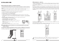
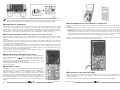
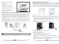
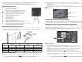
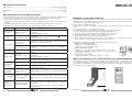
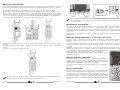
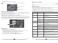
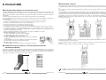
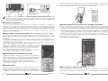
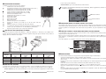
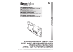
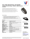
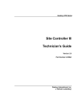
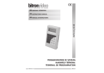
CARATTERISTICHE DI FUNZIONAMENTO E INSTALLAZIONE
INSTRUCTIONS MANUAL
OPERATING AND INSTALLATION FEATURES
MANUEL D’INSTRUCTIONS
GVM70/0 • AN6074/L
CARATERISTIQUES DE FONCTIONNEMENT ET INSTALLATION
GVM70/1 • AN6082/L
MANUALE ISTRUZIONI
MODULI VIDEO GVM70
GVM70 VIDEO MODULES
MODULES VIDEO GVM70
DS90368-001A
LBT90019
COMPONIBILITA’ VERTICALE
ITALIANO
CARATTERISTICHE GENERALI E TIPOLOGIE DI IMPIANTO
La pulsantiera DOMULAR CLASSIC EVOLUTION è basata su una filosofia modulare che permette la realizzazione
degli impianti citofonici e videocitofonici con un estrema semplicità. La pulsantiera si presenta con una finitura
grigio alluminio anodizzato, per quanto riguarda, i supporti dei moduli, le testate superiore ed inferiore, ed i
moduli.
La retro illuminazione del cartellino porta nome, è realizzata mediante diodi LED di colore BLU.
E’ disponibile una vasta gamma di prodotti per coprire le diverse necessità degli impianti citofonici e
videocitofonici.
I componenti della pulsantiera che devono essere inseriti secondo le necessità sono:
• la scatola incasso muro, che è la base di partenza di qualunque composizione;
• la visiera, che è l’elemento protettivo dalle intemperie;
• il supporto moduli, che sono la struttura portante;
• i moduli funzionali, che sono il cuore dell’impianto;
• i moduli con chiamata digitale, che sono realizzati mediante una tastiera numerica od i tasti normali;
• i moduli pulsanti, che sono il punto di partenza delle chiamate verso gli utenti; e sono disponibili in
versioni ad 1 tasto (2 utenti), a 2 tasti (4 utenti) a 3 tasti (6 utenti) e a 4 tasti per un massimo di 8 utenti
per modulo.
La pulsantiera modulare EVOLUTION permette di realizzare le seguenti tipologie di impianto:
• SISTEMI ANALOGICI con chiamata tradizionale
- Il sistema audio GCM 1+n e 4+n (fonia standard)
- Il sistema video GVM (video su 5 fili senza coassiale)
• SISTEMI ANALOGICI con chiamata digitale
- Il sistema €BUS (audio 2 fili e video 5 fili totali con massimo 100
utenti)
- Il sistema MDK (studiato per grossi impianti con repertorio nomi
massimo 400 utenti)
• SISTEMI 2 FILI non polarizzati
- Il sistema BFAST (2 fili non polarizzati con massimo 32 utenti)
I supporti portamoduli (KSM 70/1 - KSM 70/2 e KSM 70/3 KSM70/4) vengono forniti con la testata inferiore
in plastica, già assemblata. Si presentano con una colorazione grigio allumino (anodizzato) sia per i supporti
che per le testate. (es.AN6025/L).
Per completare la pulsantiera è sufficiente inserire il/i modulo/i nelle apposite scanalature come indicato nel
disegno.
Nel caso della realizzazione di una pulsantiera con più moduli tasti, prima di inserire il secondo modulo,
ricordarsi di svitare le due viti laterali del “Comune Pulsanti” del modulo inferiore. Interporre il distanziale in
plastica già fornito nel corredo dei supporti moduli, inserire il modulo seguente accertandosi che le 2 linguette
a forcella si inseriscano correttamente sotto le due viti del modulo precedentemente inserito (NON SERRARE
LE VITI). Eseguire tutti i passaggi come indicato nelle tre figure presenti sulla scatola imballo (e nelle figure
sottostanti).
Completare la preparazione della pulsantiera, inserendo la testata superiore e serrando a fondo, le due viti di
chiusura testata, fornite a corredo.
Nel caso di pulsantiere a più moduli, completare il montaggio con il serraggio delle due viti del modulo tasti.
A questo punto la pulsantiera è pronta e correttamente assemblata.
COMPOSIZIONE ED INSTALLAZIONE E DELLA PULSANTIERA MODULARE EVOLUTION
SCATOLA INCASSO
1,70 - 1,73 m
Per la realizzazione dell’impianto videocitofonico occorre come prima cosa stabilire il numero di utenti e
di conseguenza la dimensione della pulsantiera. Attenzione ai moduli di completamento. A questo punto
procedere con la composizione della scatola incasso come mostrato in figura. Terminata questa operazione
procedere alla muratura della composizione seguendo le indicazione del disegno seguente.
Ricordare che nell’ultimo modulo in basso, (quello a contatto con la testata inferiore) occorre piegare di
90° le due forcelle del comune pulsanti, come indicato nelle figure per evitare interferenze.
2
DS90368-001A
DS90368-001A
3
Ricordare che nel caso del montaggio di moduli tasti diversi da quello a 4 tasti il “comune pulsanti” deve
essere realizzato mediante due fili di collegamento tra il modulo superiore ed il modulo inferiore (nel caso
di impianti speciali attenersi alle indicazioni specifiche dei manuali o degli schemi di impianto).
COLLEGAMENTO DEI FILI DELL’IMPIANTO AL MODULO TASTI
COMPONIBILITA’ ORIZZONTALE
Le pulsantiere sono componibili anche in senso orizzontale (max 3 file). Per quest’applicazione, sono forniti
con i supporti moduli, dei profilati di accoppiamento da inserire nelle due scanalature esterne dei supporti
moduli adiacenti. Tale operazione deve essere tassativamente effettuata prima di fissare le testate superiori.
Quest’accessorio consente di risparmiare l’utilizzo di cornici, garantendo comunque un perfetto allineamento
delle pulsantiere. (Come indicato nelle figure presenti sulla scatola imballo e nelle figure a pag. 3).
COLLEGAMENTO COMUNE PULSANTI (Per impianti audio video standard)
Al fine di evitare i ponticelli volanti, tutti i moduli pulsanti (incluso il modulo videocitofonico a 1 tasto,
GVM70/1 AN6082/L) portano sul lato inferiore due forcelle, in corrispondenza dei due contatti “comune
pulsanti”.
Per il collegamento del comune pulsanti tra modulo e modulo, sarà sufficiente allentare la vite del primo
pulsante sul modulo inferiore, inserire la forcella e richiudere la vite. Operazione già descritta in precedenza
nel paragrafo della composizione verticale.
Se si utilizzano versioni di pulsantiere su più file, occorrerà utilizzare un filo di collegamento tra i due comuni
pulsanti delle file adiacenti. Nel caso di versioni video su più file, ma con un solo modulo per fila (configurazione
orizzontale), non essendo accessibile la vite del comune pulsanti, collegare il comune del modulo pulsanti con
un filo al morsetto CP del modulo video (GVM 70/1)
E’ inoltre sempre necessario, ponticellare il comune pulsanti di destra, con
quello di sinistra, all’interno della stessa fila.
Ancorata la pulsantiera alla scatola incasso, provvedere al cablaggio dei seguenti morsetti di ogni modulo
pulsanti:
• Morsetti P (seguito da un numero). Sono presenti su di ogni circuito tasti e devono essere collegati ai fili
della colonna montante che sono collegati al filo “C” del monitor oppure al filo di chiamata del citofono.
• Morsetto CD “comune diodi”. (Operazione richiesta in tutti gli impianti 1+n e video 5 fili )Tale filo deve
essere portato dal modulo audio o video 5 fili al morsetto denominato CD di tutti i circuiti tasti presenti
nella composizione (tale collegamento deve essere eseguito tranne nel caso in cui si stia realizzando un
impianto particolare, in tal caso seguire le istruzioni di collegamento fornite a corredo).
Qualora si stiano realizzando impianti diversi da quelli tradizionali fare riferimento alle istruzioni di montaggio
allegate ai singoli prodotti. Per i dettagli vedere la figura seguente.
COLLEGAMENTO ILLUMINAZIONE PULSANTIERA
L’illuminazione dei cartellini è ottenuta collegando i fili dell’alimentazione
identificata dai morsetti ~ e ~ presenti nella morsettiera del gruppo audio/
video e anche 0 e ~ nel gruppo audio ai due morsetti identificati con “L”
presenti sul circuito stampato posizionato dietro al modulo pulsanti. (per i
dettagli vedere le istruzioni dei moduli pulsanti).
Tale cablaggio è da effettuare per ciascun modulo pulsanti sia a 1 a 2 a 3 o a
4 tasti. Vedere figura.
MONTAGGIO A MURO
Terminata la fase di composizione della pulsantiera, provvedere all’ancoraggio
delle testate inferiori alle scatole incasso mediante le viti in dotazione ai
“supporti moduli”, procedere con il collegamento dei fili dell’impianto
descritto nel paragrafo seguente e quindi, realizzato l’allineamento corretto
provvedere nello stesso modo al fissaggio della testata superiore. Attenzione:
Nelle composizioni a più moduli orizzontali ricordarsi di fissare tutte le viti
sia inferiori che superiori, in caso contrario la pulsantiera potrebbe risultare
non perfettamente aderente al muro ed incorrere in problemi d’infiltrazione
d’acqua.
4
UTILIZZO DEL CARTELLINO PORTA NOME
Il tasto di chiamata nei moduli ove presente è studiato per accogliere sia il foglio di PVC bianco, fornito a
corredo, sul quale poter scrivere con un pennarello indelebile sia il cartellino porta nome inciso che l’utente
dovrà far realizzare.
Per quanto riguarda la prima ipotesi l’unica accortezza è di utilizzare un pennarello indelebile
DS90368-001A
DS90368-001A
5
Per quanto riguarda il cartellino inciso
bisogna rispettare scrupolosamente le
seguenti indicazioni:
• Le dimensioni fornite dal disegno
sottostante sia per il mono che per il
bi utente;
• La dimensione del catrattere inciso
per facilitare la visione (utilizzare
un carattere con incisione da 0.7mm
compatibilmente con i nomi da
scrivere;
• Il colore neutro della scritta incisa
(nel caso in cui venga realizzato in
modo colorato la visibilità del nome
risulterebbe molto bassa).
NOTA
La piastrina porta-nome deve avere le dimensioni descritte.
MODULO AUDIOVIDEO GVM 70 EVOLUTION
DESCRIZIONE DEL MODULO VIDEO GVM70/0 e GVM70/1 in versione EVOLUTION
Il modulo audio/video GVM70 è la base dell’impianto videocitofonico a 5 fili senza cavo coassiale, viene fornito
in versione grigio anodizzato, ed in due versioni di allestimento con o senza il tasto di chiamata.
Il modulo predisposto con il tasto di chiamata (GVM70/1), permette la realizzazione dei impianti completi
mono o bi utente in una sola unità, senza la necessita di aggiungere un ulteriore modulo tasti. Il tasto di
chiamata in questo caso viene fornito precablato come indicato nei disegni, e completo di piastra diodi.
TRASFORMAZIONE TASTO DA SEMPLICE A DOPPIO
I moduli pulsanti vengono forniti con i tasti in configurazione monoutente con cartellino unico. La pressione
del tasto sia dalla parte destra che da quella sinistra genererà la chiamata sia sul norsetto P1 che sul morsetto
P2. In questa configurazione va ricordato che gli utenti collegabili sono esclusivamente uno per tasto, e che il
cablaggio del filo di chiamata dovrà necessariamente essere eseguito sui morsetti DISPARI (P1 P3 P5 P7).
Per configurare il tasto da singolo a doppio utente, bisogna effettuare le due attività seguenti.
• Per quanto riguarda la parte elettrica basterà tagliare il o i ponticelli J1--J4 presenti sul circuito e collegare
tutti i fili dei pulsanti (P1,P2,P3…….). Per effettuare questa operazione eè sufficiente una forbice da
elettricista.
• Per quanto riguarda la parte meccanica, è necessario trasformare l’alloggiamento del cartellino porta nome
esterno da singolo a doppio. Per fare ciò, bisogna intervenire sulla parte esterna del tasto modificando il
porta cartellino. L’accessibilità è ottenuta utilizzando l’apposito attrezzo in dotazione, facendo leva in uno
qualsiasi dei quattro angoli del copritasto. Gli accessori porta cartellini e cartellini in PVC sono forniti a
corredo dei moduli tasti.
Per la trasformazione del tasto da singolo a doppio, operare nel modo indicato nelle figure seguenti.
A
A1
B
Le caratteristiche del sistema videocitofonoico GVM70 / GVCM70 sono:
• 5 fili per il collegamento dei monitor al posto esterno;
• Alimentatore unico centralizzato;
• Gestione integrata dell’elettroserratura
• Posti esterni e videocitofoni alimentati da un unico alimentatore;
• Retro illuminazione dei cartellini mediante diodi LED
• Possibilità di realizzare impianti misti AUDIO/VIDEO ed AUDIO
• Scatola relais per la gestione degli impianti con piu posti esterni (Primario, Secondari);
• Possibilità di gestire fino a 2 monitor in parallelo per ciascun utente senza necessita di componenti
aggiuntivi;
• Possibilità di realizzare un impianto a COLORE mediante il modulo con telecamera a colore (GVCM70);
• Monitor utilizzabili T-Line, MV1000 e MV3000 sia BIANCO/NERO che COLORE;
• Citofoni utilizzabili: AN9136 con fonia 1+N e T-Line AV1407/002;
Effettuare questa operazione con l’impianto scollegato o spento.
6
L’illuminazione del cartellino è realizzata mediante LED di colore BLU che garantiscono una maggior
affidabilità.
Nel gruppo in versione evolution audio/video GVM70/1, per configurare il tasto di chiamata da singolo a doppio
oltre le operazioni meccaniche riguardanti il cartellino porta nome bisogna effettuare le seguenti operazioni:
- rimuovere con attenzione la parte posteriore (plastica) del gruppo spostandola verso l’alto
- effettuare il taglio del ponticello (o della resistenza) presente nella parte centrale del circuito montato al
di sopra del foro. Tale operazione deve essere effettuata con attenzione.
- estrarre i due fili dal mammouth e collegarli singolarmente ai fili della chiamata (in colonna) di 2 utenti
differenti;
- assemblare nuovamente la parte plastica precedentemente rimossa.
Fare riferimento alle due foto seguenti che illustrano le operazioni da eseguire:
DS90368-001A
DS90368-001A
7
• Cablaggio in derivazione tramite distributore o in entra esci direttamente sui morsetti del monitor;
• Autoaccensione dell’impianto direttamente dal monitor con il tasto specifico;
• Possibilità di realizzare impianti con chiamata digitale mediante i moduli della serie €BUS
DESCRIZIONE DEI MORSETTI
Talvolta, può rendersi necessario variare tale regolazione. In tal caso procedere come segue:
- Volume esterno: agire sul trimmer EXT in senso orario, per aumentare il volume ed in senso opposto per
ridurre il volume.
- Volume interno: agire sul trimmer INT in modo analogo al precedente.
Se nell’impianto si verificasse un innesco Larsen (fischio), ridurre leggermente entrambi i volumi, per
eliminarlo.
Il modulo si presenta con i seguenti morsetti
~
Alimentazione elettroserratura
AP
Comando apertura porta (elettroserratura tra AP e ~)
~
Alimentazione proveniente dall’alimentatore A70 (12Vac)
~
Alimentazione proveniente dall’alimentatore A70(12Vac)
+
Positivo proveniente dall’alimentatore A70 (20Vdc)
Negativo proveniente dall’alimentatore A70 (20Vdc)
1
Comune impianto video
3
Alimentazione dei monitor in colonna
A
Segnale video negativo
B
Segnale video positivo
V
Segnale video 75 OHM
S
Massa segnale video
0
Riferimento della fonia dell’impianto
CP
Comune pulsanti (da collegare con filo ai due lati dei pulsanti)
CH
Ripetizione chiamata per comando dispositivi remoti.
CD
Comune Diodi deve essere collegato ai morsetti CD dei moduli pulsanti.
(vedere istruzioni nel caso di impianti particolari)
9
Segnale di sincronizzazione per dispositivi digitali
Volume interno
Volume esterno
PROTEZIONE AL CORTOCIRCUITO SULLA CHIAMATA
Un eventuale cortocircuito sui morsetti di chiamata, farà intervenire la protezione in corrente che interrompe
le chiamate per alcuni secondi. Trascorso tale tempo, il posto esterno sarà nuovamente in grado di generare
una nuova chiamata. Se non verrà eliminato il cortocircuito, il ciclo si ripeterà alla successiva chiamata.
FUNZIONE JUMPER J1 PER PROTEZIONE BOBINA ELETTROSERRATURA
REGOLAZIONE INCLINAZIONE TELECAMERA
La telecamera che equipaggia i moduli video GVM70/0 – AN6074/L e GVM 70/1 – AN 6082/L, è installata su
un apposito supporto che può essere orientato al fine di ottimizzare l’angolo di ripresa verticale. Per la sua
regolazione procedere come indicato in figura.
Il modulo GVM70 è settato in origine con una protezione sul comando AP che ne permette l’azionamento
temporizzato per un tempo massimo di 3 sec.
Qualora sia necessario rimuovere questa protezione è necessario separare il GVM dal frontale, aprire i 2 gruppi
in plastica e inserire il jumper J1, posizionato sul lato inferiore del CS vicino al relè apriporta. Per questa
operazione si consiglia di contattare il servizio tecnico Bitron Video.
0
m 1.9
m 1.80
m 1.70
m 1.4
0
m1
.30
J1
m 0.50
COLLEGAMENTI
TABELLA SEZIONE CONDUTTORI
Distanza
Filo
1/3
Filo
C/E/T/P
Filo
A-B
Filo
+/-/al/al-
m
mm2
mm2
mm2
mm2
50
0,75
0,5
0,3
1,5
100
1,50
0,75
0,30 twisted
200
2,50
1,00
0,30 twisted
REGOLAZIONE DEI VOLUMI
Il gruppo video, viene regolato in fase di produzione sui valori ottimali, per un impianto di media grandezza.
8
DS90368-001A
Per quanto riguarda i collegamenti, è opportuno tenere presente alcune regole fondamentali:
- rispettare scrupolosamente le sezioni indicate nella tabella.
- evitare di posare i cavi dell’impianto vicino a quelli della normale rete elettrica (almeno 30 cm di
distanza).
- Collegare i fili di massa esattamente come indicato negli schemi applicativi per evitare ronzii.
- Posizionare l’alimentatore ad una distanza massima dal Posto Esterno, di 50 mt.
- Utilizzare per la connessione dei terminali ~ e ~, anche + e - dei conduttori da 1,5 mm2.
- Rispettare inoltre scrupolosamente i collegamenti indicati sullo schema, al fine di evitare ronzii sulla
fonia
- I morsetti di chiamata dovranno essere utilizzati esclusivamente per l’uso previsto onde evitare
funzionamenti anomali sulla fonia.
DS90368-001A
9
CARATTERISTICHE TECNICHE
ENGLISH
Alimentazione: .........................................................................................12 V c.a. (80 mA in stand-by)
20 Vc.c. 0,3 A
Dimensioni: ........................................................................................................... 110 x 120 x 56 mm
Peso: ......................................................................................................................................280 gr
FUNZIONAMENTO E RISOLUZIONE DEI PROBLEMI
Guasto
Pulsantiera non
illuminata
Fonia e video
mancante
Fonia mancante
Video mancante
Monitor spento
Chiamata non
disponibile
Immagine
non corretta o
disturbata
Fonia disturbata
Funzione
Apriporta non
disponibile
10
Causa
Mancanza
dell’alimentazione
12Vca
Mancanza
alimentazione 12Vca
Errata o mancante
connessione del
morsetto CD
Possibile risoluzione
• Fili alimentatore non connessi ai morsetti L delle
pulsantiere
• Fusibili alimentatore interrotti
• Fili alimentatore non connessi ai morsetti ~ e ~ del gruppo
video GVM
• Fusibili alimentatore interrotti
Controllare le connessioni del filo CD proveniente dal gruppo
GVM al morsetto CD delle pulsantiere
Controllare l’effettiva connessione dei morsetti P delle
Mancanza connessione
pulsantiere con i morsetti C del monitor o con il morsetto 2
dei fili dell’impianto
del citofono
Mancanza connessione Controllare i fili A e B del gruppo video o del monitor
fili A e B
collegato.
• Fili alimentatore non connessi ai morsetti + e – del gruppo
Mancanza
video GVM
alimentazione 20Vcc
• Fusibili alimentatore interrotti
Errata connessione dei
Controllare i fili 1 e 3 del gruppo video o del monitor collegato
fili 1 e 3
Errata connessione del Controllare il collegamento tra il morsetto P della pulsantiera
filo C
ed il morsetto C del monitor
Mancanza
In alcuni monitor è necessaria l’alimentazione ai morsetti 1 e 3
alimentazione
per generare la chiamata
Fili A e B collegati non correttamente oppure disturbi prelevati
Problemi nel
dai cavi ad alta tensione adiacenti. Controllare il passaggio dei
collegamento dei fili
cavi.
AeB
Controllare posizionamento dei fili della colonna montante.
Problemi nel cablaggio Controllare eventuali dispositivi elettrici nelle vicinanze quali
apricancello elettrico, sistemi di illuminazione o altri dispositivi
dei fili dell’impianto
simili.
• Controllare i fili 1 e CD dell’impianto,
• Controllare le sezioni dei conduttori utilizzati e le distanze
Problemi nel cablaggio
di esercizio
dei fili dell’impianto
• Nel caso di distanze eccessive utilizzare l’alimentatore
supplementare
DS90368-001A
GENERAL FEATURES AND SYSTEM TYPES
The DOMULAR CLASSIC EVOLUTION panel is the expression of a modular concept for installing doorphone and
video doorphone systems with extreme ease. The panel, the module supports, the upper and lower heads and
the modules have a grey anodised aluminium finish.
The name tags are backlit by blue LEDs.
A wide range of products is available to provide answers to all doorphone and video doorphone system
needs.
The panel components to be assembled as needed are:
• the wall embedding box (this element is the starting point for all compositions);
• the hood (this element protects the device from the weather elements);
• the module supports (these elements are the structural part of the device);
• the functional modules (these elements are the heart of the system);
• digital calling modules (with keypad or traditional buttons);
• button modules (these elements are the starting point for calls to users) - 1 button (2 users), 2 buttons (4
users), 3 button (6 users) and 4 buttons (up to 8 user) per module.
The EVOLUTION modular panel can be used in the following types of systems:
• Traditional call ANALOGUE SYSTEMS
- GCM audio 1+n e 4+n (standard audio)
- GVM video (5-wire video without coax)
• Digital call ANALOGUE SYSTEMS
- €BUS system (2-wire audio and 5-wire video with up to 100 users)
- MDK system (designed for large systems with a name directory
containing up to 400 users)
• Non-polarised 2-WIRE SYSTEMS
- BFAST system (2 wires, non-polarised, with up to 32 users).
EVOLUTION MODULAR PANEL COMPOSITION AND INSTALLATION EMBEDDING BOX
The first thing you need to establish when installing a video doorphone system is the number of users and
consequently the dimensions of the panel. Remember the completion modules. At this point, you can start
by mounting the embedding box, as shown in the figure. At the end of this operation, embed the box in the
masonry as shown in the drawing below.
1,70 - 1,73 m
Il funzionamento del posto esterno audio video GVM è di tipo molto tradizionale, il generatore della chiamata
e tutte le funzioni necessarie per l’accensione dei monitors sono all’interno del modulo audio video.
In impianti tradizionali la pressione del tasto di chiamata genera due eventi,
• la generazione della nota bitonale inviata in colonna ed utilizzata come suoneria e come accensione del
monitor;
• l’accensione della parte video del gruppo con l’invio dei segnali video e alimentazione in colonna.
La tabella seguente illustra la possibile risoluzione dei problemi in impianti tradizionali.
DS90368-001A
11
VERTICAL CONFIGURATION
The module holder supports (KSM 70/1 - KSM 70/2 and KSM 70/3 KSM70/4) are provided with a preassembled
lower plastic head. Both the supports and the heads have an anodised grey aluminium colour (e.g. AN6025/
L).
To complete the panel, simply insert the module(s) in the specific grooves, as shown in the drawing.
When making a panel with several button modules, before inserting the second module, remember to loosen
the two screws on the side of the “Button Common” of the lower module. Arrange the plastic spacer included
with the module support, insert the next module making sure that the 2 forked tabs are correctly inserted
under the two screws of the previously inserted module (DO NOT TIGHTEN THE SCREWS). Proceed following the
steps shown in the free figures on the embedding box (and the figures below).
When assembling button modules with other than 4 buttons, connect two wires between the upper and the
lower module for the “button common” (follow the specific instructions shown in manuals and diagrams
for special systems).
HORIZONTAL CONFIGURATION
The panels may also be assembled horizontally (up to 3 rows). Coupling profiles are included with the module
supports for this application. Insert the profiles in the two external grooves of the two module supports
arranged side by side. Perform this operation before fixing the upper heads. The profile accessory allows to
perfectly align the panels without the use of frames (as shown in the figures on the packing and in the figures
on page 12).
button common to the left button common in the same row (unless otherwise specified in specific system
instructions).
BUTTON COMMON CONNECTION (in standard audio-video systems)
Complete the panel preparation by inserting the upper head and tightening the two head closing screws
included.
For panels formed by several modules, complete assembly by tightening the two screws of the button
module.
The panel is now ready and correctly assembled.
In order to avoid in-line jumpers, all button modules (including the 1-button GVM70/1 AN6082/L video
doorphone module) have two forks on the lower side in correspondence of the two “button common”
contacts.
To connect the button common between module and module, simply loosen the screw of the first button on
the lower module, insert the fork and close the screw. The operation is described in the vertical assembly
paragraph.
If multiple row panel versions are used, use one connection wire between the two button commons of the
adjacent rows. For video versions on multiple rows with only one module in each row (horizontal configuration),
connect the button module common with a wire to the CP terminal of the video
module (GVM 70/1), since the button common screw is not accessible.
You will still need to jump the right button common to the left button common
within the same row.
PANEL BACKLIGHT CONNECTION
The name tags lighting is obtained by connecting the power wires identified by
terminals ~ and ~ on the audio/video or 0 ~ on the audio group unit to the two
terminals identified by letter “L” on the printed circuited positioned behind the
module. (Refer to the button module instructions for details).
Proceed in the same manner for each button module (1, 2, 3 or 4 buttons).
See figure.
WALL INSTALLATION
Remember to fold the two button common forks by 90° on the last module on the bottom (the one in
contact with the lower head) as shown in the figures to avoid interference.
12
DS90368-001A
After assembling the panel, anchor the lower heads to the embedding boxes
using the screws included with the “module supports”. Proceed by connecting
the system wires as described in the following paragraph and then, once
correctly aligned, fasten the upper head in the same manner. Important: In
horizontal configurations, remember to fix all the upper and lower screws:
otherwise the panel may not adhere perfectly to the wall and water infiltration
may occur.
DS90368-001A
13
In the first case, remember to use a
permanent ink pen.
Follow the indications below for engraved
name tags:
• The dimensions are shown in the
drawing below (one and two users).
• Choose the right size of the engraved
character to make it easy to read (0.7
mm size characters are recommended,
compatible with the name to be
engraved).
• Choose a neutral colour for the engraved
letters (visibility is very low if coloured
letters are used).
NOTE
The name-tag shall have the following dimensions.
SYSTEM WIRE CONNECTION TO BUTTON MODULE
After anchoring the panel to the embedding box, connect the wiring to the following terminals of each
button
module:
• P (+ digit) terminals. These terminals are present on each button circuit and must be connected to the
riser column wires, which are in turn connected either to the “C” wire of the monitor or to the calling wire
of the doorphone.
• CD “common diode” terminal. (The operation is required for all 1+n and 5-wire systems). This wire must be
connected from the audio or 5-wire video module to the CD terminal of all button circuits in the assembly
(for special systems, follow the specific instructions provided).
Refer to the specific assembly instructions attached to the single products when making systems different from
a traditional system. Refer to the following figure for details.
BUTTON TRANSFORMATION FROM SIMPLE TO DOUBLE
The button modules are supplied with buttons in one-user, one-name-tag configuration. Pressing either the
right button or the left button will generate a call either to terminal P1 or to terminal P2. In this configuration,
remember that only one user can be connected to each button and that the calling wire must be connected to
the ODD terminals (P1 P3 P5 P7).
Proceed with the following two steps to configure the button from one-user to two-user configuration:
• For the electrical part, simply cut jumper(s) J1--J4 on the circuit and connect all the wires of buttons
(P1,P2,P3…….). Electrical cutters may simply be used for this operation.
• As concerns the mechanical part, the name tag housing must be transformed from a single housing into a
double housing. To do this, you will be need to change the name tag from the outside of the button. Use
the specific tool supplied to open the unit by levering in any one of the four button cover corners. The name
tag accessories and PVC name tags are included with the button modules.
Proceed as shown in the following figures to transform from single to double button configuration.
A
A1
B
The system must be either disconnected or off to perform this operation.
NAME TAG USE
The calling button (in modules where applicable) is designed to accommodate either the included white PVC
sheet (on which the name may be written in permanent ink) and the engraved name tag provided by the
user.
14
DS90368-001A
DS90368-001A
15
GVM 70 EVOLUTION AUDIO-VIDEO MODULE
DESCRIPTION OF TERMINALS
DESCRIPTION OF EVOLUTION VIDEO MODULE GVM70/0 AND GVM70/1
The module has the following terminals:
~
Lock power
AP
Door open command (lock between AP and ~)
~
Power from A70 power unit (12Vac)
~
Power from A70 power unit (12Vac)
+
Positive from A70 power unit (20Vdc)
Negative from A70 power unit (20Vdc)
1
Video system common
3
Column monitor power
A
Negative video signal
B
Positive video signal
V
75 OHM system signal
S
Video signal ground
0
System audio reference
CP
Button common (to be connected with wire to the two sides of the
buttons)
CH
Call repeat for controlling remote devices
CD
Diode common to be connected to CD terminals of button modules (see
instructions for special systems)
9
Digital device synchronisation signal
The GVM70 audio-video module is the basis of the 5-wire no coax video doorphone system. It is anodised grey
in colour and two versions are available (with or without calling button).
The setup module with calling button (GVM70/1) allows to make complete one or two user system with only
one unit and without the need for additional button modules. The calling button in this case is pre-wired as
shown in the drawings and complete with diode plate.
CAMERA INCLINATION ADJUSTMENT
The camera fitted in GVM70/0 – AN6074/L and GVM 70/1 – AN 6082/L video modules is installed on a specific
support and may be adjusted to optimise the vertical shooting angle. Proceed as shown in the figure to
adjust.
0
m 1.9
m 1.80
m 1.4
0
m1
.30
m 1.70
The name tag is lit by means of high-reliability blue LEDs.
In evolution audio/video GVM70/1 group, to configure the call button from single to double it is necessary to
perform the mechanical operations on the name holder tag and the following operations:
- remove with care the group back side (plastic) by moving it up;
- cut the jumper (or the resistor) in the middle of the circuit placed over the hole; this operation must be
performed with care;
- take out the wires from the terminal block and connect each one to the call wires (in column) of 2 different
users;
- mount again the plastic part previously removed;
Refer to the following two photos that show the operations to be performed:
m 0.50
The features of the GVM70 / GVCM70 video doorphone system are:
• 5 wires connecting the monitor to the door panel.
• One centralised power unit.
• Integrated lock management.
• Apartment stations and video doorphone powered by the same, single power unit.
• Name tag backlighting with LEDs.
• Possibility of making combined AUDIO-VIDEO and VIDEO systems.
• Relay box for managing systems with several door panels (Primary, Secondary).
• Possibility of managing up to 2 monitors in parallel for each user without additional components.
• Possibility of making a COLOUR system by using a colour camera (GVCM70).
• Possibility of using T-Line, MV1000 and MV3000 monitors, either BLACK AND WHITE or COLOUR.
• Possibility of using AN9136 with 1+N audio and T-Line AV1407/002 module doorphones.
• Extension wiring via distributor or in in-out mode directly to device terminals.
• System auto power-on directly from the monitor using the specific button.
• Possibility of making digital call systems using UBUS series modules.
16
DS90368-001A
WIRE DIAMETER AND CROSS-SECTION AREA
Distance
Wire
1/3
Wire
C/E/T/P
Wire
A-B
Wire
+/-/al/al-
m
mm2
mm2
mm2
mm2
1,5
50
0,75
0,5
0,3
100
1,50
0,75
0,30 twisted
200
2,50
1,00
0,30 twisted
VOLUME ADJUSTMENT
The video unit settings are optimal for a system of average size by default.
The settings may however need to be changed. Proceed as follows in such a case (Fig. 5):
- External volume: turn trimmer EXT clockwise to turn the volume up and anticlockwise to turn it down.
DS90368-001A
17
-
TECHNICAL SPECIFICATIONS
Internal volume: turn trimmer INT in a similar way.
Power: .......................................................................................................... 12 Vac (80 mA stand-by)
20 Vdc 0.3 A
Dimensions: ........................................................................................................... 110 x 120 x 56 mm
Weight: ....................................................................................................................................280 g
Turn down both volumes slightly if feedback loop howl occurs to eliminate the problem.
TROUBLESHOOTING
Internal volume
The GVM audio-video door panel is a very traditional device. The call generator and all the functions needed
to switch the monitors on are found within the audio-video module itself.
Two effects are generated when the call button is pressed in a traditional system:
• a two-tone call is generated, sent to the column, and used either to operate the ringer and to switch on
the monitor;
• the video section of the system is switched on and video and power signals are sent to the column.
The following table shows how to solve problems occurring in traditional systems.
External volume
CALL SHORT CIRCUIT PROTECTION
The protection system will cut off calls for a few seconds in the event of a calling terminal short circuit. After
this time, the door panel will be able to generate a new call. The cycle will be repeated when the next call is
generated if the short circuit problem is not solved.
ELECTRIC LOCK COIL PROTECTION, USE OF THE JUMPER J1
The module GVM 70 is equipped with a protection on the door release input that allows current to the coil
of the electric lock for a maximum time of about 3 sec. In those cases where it is necessary to by-pass this
protection it is necessary to separate the speaker set from the aluminium front panel, open the plastic housing
of the speaker and then insert the jumper J1 located on the lower part of the circuit near to the lock release
relay. For this operation it is suggested to get in contact with the Bitron Video technical centre.
Fault
Cause
Panel does not
light up
No power 12Vca
No audio and
video
No power 12Vca
No audio
No video
Incorrect or missing
connection of CD
terminal
No system wire
connection
No connection of
wires A and B
No power 20Vcc
J1
Monitor off
Call not available
CONNECTIONS
No power
The following rules must be observed for connections:
- Follow the instructions shown in the table carefully.
- Avoid installing system wires close to electrical mains wires (they should be at least 30 cm apart).
- Connect the ground wires exactly as shown in the diagrams to avoid buzzing.
- Position the power supply at a maximum distance from the door panel of 50 metres.
- Use 1.5 mm2 wires for connecting terminals ~ and ~ for + and - Also respect the connections shown on the diagram to prevent noise.
- Calling terminals must be used only for their intended use to avoid audio faults.
18
Wrong connection of
wires 1 and 3
Wrong connection of
wire C
DS90368-001A
Picture not sharp
or disturbed
Problems in the
connection of wires A
and B
Disturbed audio
System wiring
problems
Door opening
function not
working
System wiring
problems
DS90368-001A
Possible solution
• Power unit wires not connected to L terminals of door
panels
• Power unit fuses blown
• Power unit wires not connected to terminals ~ and ~ of the
GVM video unit
• Power unit fuses blown
Check CD wire connections from GVM unit to CD terminal of
panels
Check that P terminals on the panels are actually connected to
C terminals of the monitor or to terminal 2 of the door phone
Check wires A and B of the video unit or connected monitor
• Power unit wires not connected to terminals + and - of the
GVM video unit
• Power unit fuses blown
Check wires 1 and 3 of the video unit or connected monitor
Check connection between terminal P of panel and terminal C
of monitor
Power to terminals 1 and 3 for generating the call is needed
for some monitors
Wires A and B not correctly installed or interference from nearby
high-voltage wires. Check wire installation.
Check position of wires in riser column.
Check nearby electrical devices, such as gates, lights or other
similar devices.
• Check wires 1 and CD in the system
• Check wire cross-section area and distances
• Use a supplementary power unit if the distances are
excessive
19
COMPOSITION VERTICALE
FRANÇAIS
CARACTERISTIQUES GENERALES ET TYPES D’INSTALLATION
La platine DOMULAR CLASSIC EVOLUTION est basée sur une philosophie modulaire qui permet de réaliser des
installations d’interphones et de vidéophones avec une extrême simplicité. La platine se présente avec une
finition grise en aluminium anodisé, au niveau des supports des modules, des châssis supérieur et inférieur et
des modules.
Le rétro-éclairage de l’étiquette porte-nom est réalisé par des diodes DEL de couleur BLEUE.
Une vaste gamme de produits est disponible pour couvrir les différentes exigences des installations d’interphones
et de vidéophones.
Les composants de la platine qui doivent être introduits selon les nécessités sont les suivants :
• le boîtier d’encastrement mural, qui est la base de départ de n’importe quelle composition ;
• la visière, qui est l’élément de protection contre les intempéries ;
• le support des modules, qui correspond à la structure portante ;
• les modules fonctionnels, qui constituent le cœur de l’installation ;
• les modules avec appel numérique, qui sont réalisés avec une platine numérique ou des touches normales ;
• les modules touches, qui sont le point de départ des appels vers les utilisateurs, sont disponibles en versions
à 1 touche (2 utilisateurs), à 2 touches (4 utilisateurs), à 3 touches (6 utilisateurs) et à 4 touches pour un
maximum de 8 utilisateurs par module.
La platine modulaire EVOLUTION permet de réaliser les typologies d’installation ci-dessous:
• SYSTEMES ANALOGIQUES avec appel traditionnel
- le système audio GCM 1+n et 4+n (phonie standard)
- le système vidéo GVM (vidéo sur 5 fils sans coaxial)
• SYSTEMES ANALOGIQUES avec appel numérique
- Le système €BUS (audio 2 fils et vidéo 5 fils totaux avec 100 utilisateurs
au maximum)
- le système MDK (conçu pour des installations de dimensions importantes
avec une rubrique noms de 400 utilisateurs maximum)
• SYSTEMES 2 FILS non polarisés
- le système BFAST (2 fils non polarisés avec 32 utilisateurs maximum)
les supports porte-modules (KSM 70/1 - KSM 70/2 et KSM 70/3 KSM70/4) sont fournis avec le châssis inférieur
en plastique, déjà assemblé. Les supports et les châssis sont de couleur gris aluminium (anodisé). (ex.AN6025/
L).
Pour compléter la platine, il suffit d’introduire le(s) module(s) dans les rainures prévues qui sont indiquées
sur le dessin.
En cas de réalisation d’une platine avec plusieurs modules touches, avant d’introduire le deuxième module, se
rappeler de dévisser les deux vis latérales du “Commun des touches” du module inférieur. Intercaler l’entretoise
en plastique fournie de série avec les supports modules et introduire le module ci-dessous en vérifiant que les
2 languettes à fourche sont introduites correctement sous les deux vis du module fixé auparavant. (NE PAS
SERRER LES VIS) Suivre toutes les étapes indiquées par les trois figures situées sur le boîtier d’emballage (et
par les figures ci-dessous).
Compléter la préparation de la platine, en positionnant le châssis supérieur et en serrant à fond les deux vis
de fermeture du châssis fournies de série.
En cas de platines dotées de plusieurs modules, terminer le montage en serrant les deux vis du module
touches.
Au terme de cette procédure, la platine est prête et correctement assemblée.
COMPOSITION ET INSTALLATION DE LA PLATINE MODULAIRE EVOLUTION
BOITIER D’ENCASTREMENT
1,70 - 1,73 m
Pour réaliser l’installation de vidéophones, il faut d’abord définir le nombre d’utilisateurs et par conséquent la
dimension de la platine. Attention aux modules de finition. A cette étape, continuer avec la composition du
boîtier d’encastrement comme illustré à la figure. Au terme de cette opération, procéder au maçonnage de la
composition conformément aux indications du dessin ci-dessous.
Se rappeler de plier à 90° les deux fourches du fil commun touches du dernier module en bas (celui en
contact avec le châssis inférieur) selon les indications des figures pour éviter toute interférence.
20
DS90368-001A
DS90368-001A
21
adéquat, suivre la même procédure pour la fixation du châssis supérieur. Attention : Dans les compositions à
plusieurs modules horizontaux, veiller à fixer toutes les vis aussi bien inférieures que supérieures, pour que la
platine adhère parfaitement au mur et éviter des problèmes d’infiltration d’eau.
Se rappeler qu’en cas de montage de modules touches différents de celui à 4 touches, le “commun des
touches” doit être réalisé au moyen de deux fils de raccordement qui seront fixés entre le module supérieur
et le module inférieur (dans le cas d’installations spéciales, respecter les indications spécifiques des
manuels ou des schémas d’installation)
COMPOSITION HORIZONTALE
Les platines peuvent également être composées selon une configuration horizontale (avec un maximum de
3 rangées). Pour cette application, les supports des modules sont fournis avec des profilés d’accouplement à
glisser dans les deux rainures externes des supports des modules adjacents. Il est impératif d’exécuter cette
opération avant de fixer les châssis supérieurs. Cet accessoire permet d’économiser l’utilisation de cadres et
garantit un parfait alignement des platines. (Conformément aux indications des figures situées sur le boîtier
d’emballage ou les figures page 21).
BRANCHEMENT DU COMMUN DES TOUCHES (dans les installations audio vidéo standard)
Pour éviter les liaisons volantes, tous les modules touches (y compris le module vidéophone à 1 touche,
GVM70/1 AN6082/L) sont dotés de deux fourches du côté inférieur, au niveau des deux contacts du “commun
des touches“.
Pour raccorder le commun des touches entre les modules, il suffit de desserrer la vis de la première touche sur
le module inférieur, d’introduire la fourche et de serrer la vis. Opération déjà décrite précédemment dans le
paragraphe de la composition verticale.
En cas d’utilisation de versions de platines dotées de plusieurs rangées, il faut utiliser un fil de raccordement
entre les deux communs des touches des rangées adjacentes. En cas de
versions vidéo sur plusieurs rangées, mais avec un seul module par rangée
(configuration horizontale), il est nécessaire de raccorder le commun du
module des touches avec un fil à la borne CP du module vidéo (GVM 70/1) en
raison de l’inaccessibilité de la vis du commun des touches.
Il est en outre toujours nécessaire d’exécuter un strap entre le commun des
touches de droit et celui de gauche, au sein de cette rangée.
BRANCHEMENT DES FILS DE L’INSTALLATION AU MODULE DES TOUCHES
Après avoir fixé la platine au boîtier d’encastrement, procéder au câblage des bornes du module d’appel:
• Bornes P (suivi d’un numéro). Elles sont présentes sur chaque circuit de touches et doivent être raccordées
aux fils de la colonne montante qui sont branchés au fil “C” du moniteur ou au fil d’appel de l’interphone.
• Borne CD “commun des diodes”. (Opération requise dans toutes les installations 1+n et vidéo 5 fils) Ce fil
doit être porté du module audio ou vidéo 5 fils à la borne dénommée CD de tous les circuits de touches
présents dans la composition (cette liaison doit être exécutée sauf dans le cas de la réalisation d’une
installation particulière où il faudra suivre les instructions de branchement fournies de série).
En cas de réalisation d’installations différentes des installations habituelles, se référer aux instructions de
montage fournies avec chaque produit.
Pour les détails, consulter la figure ci-dessous.
BRANCHEMENT DE L’ECLAIRAGE DE LA PLATINE
L’éclairage des étiquettes est obtenu en branchant les fils de l’alimentation
identifiée par les bornes ~ et ~ situées dans le bornier du groupe audio/vidéo
at 0 at ~ dans du groupe audio aux deux bornes identifiées par la lettre “L”
situées sur le circuit imprimé positionné derrière le module touches. (pour les
détails, consulter les instructions relatives aux modules touches).
Ce câblage doit être exécuté pour chaque module de touches aussi bien à 1, 2,
3 ou 4 touches. Voir figure.
MONTAGE MURAL
UTILISATION DE L’ETIQUETTE PORTE-NOMS
Au terme de la phase de composition de la platine, il faut fixer les châssis
inférieurs sur boîtiers d’encastrement au moyen des vis fournies avec les
supports modules. Procéder au raccordement des fils de l’installation selon
les indications du paragraphe ci-dessous et après avoir obtenu l’alignement
22
La touche d’appel dans les modules (si présente) est conçue pour accueillir aussi bien la feuille de PVC blanche,
fournie de série, sur laquelle il est possible d’écrire avec un marqueur indélébile, que l’étiquette porte-noms
DS90368-001A
DS90368-001A
23
gravée que l’utilisateur fera réaliser.
Dans le premier cas de figure, l’unique condition
consiste à utiliser un marqueur indélébile.
Dans le cas de l’étiquette gravée, il faut
respecter scrupuleusement les indications
suivantes:
• Les dimensions fournies par les dessins
ci-dessous aussi bien en cas d’utilisateur
unique qu’en cas de deux utilisateurs;
• La dimension du caractère gravé pour
simplifier la lecture (utiliser un caractère
avec gravure de 0,7 mm en fonction des
noms à écrire;
• La couleur neutre des lettres gravées (en cas
de réalisation colorée, la visibilité du nom
sera très faible).
NOTE
La plaque porte-nom doit avoir les dimensions suivantes.
MODULE AUDIO VIDEO GVM 70 EVOLUTION
DESCRIPTION DU MODULE VIDEO VIDEO GVM70/0 et GVM70/1 en version EVOLUTION
Le module audio/vidéo GVM70 est la base de l’installation de vidéophones à 5 fils sans câble coaxial, il est
proposé en version gris anodisé et en deux versions avec ou sans la touche d’appel.
Le module pré-équipé de la touche d’appel (GVM70/1), permet de réaliser des installations complètes mono- ou
bi-utilisateur dans une seule unité, sans recourir à l’ajout d’un module de touches supplémentaire. La touche
d’appel est dans ce cas fournie pré-câblée conformément à l’illustration des dessins et dotée de la plaque à
diodes.
TRANSFORMATION DE TOUCHE SIMPLE A TOUCHE DOUBLE
Les modules touches sont fournis avec une configuration des touches de type mono-utilisateur avec une
étiquette unique. La pression de la touche, aussi bien du côté droit que du côté gauche, déclenchera l’appel
sur la borne P1 et sur la borne P2. Cette configuration ne permet la connexion que d’un utilisateur par touche
et le câblage du fil d’appel ne doit être exécuté que sur les bornes IMPAIRES (P1 P3 P5 P7).Pour configurer la
touche de simple à double utilisateur, il faut procéder aux deux opérations suivantes.
• Au niveau de la partie électrique, il suffira de couper la ou les barrettes J1--J4 situées sur le circuit et de
raccorder tous les fils des touches (P1,P2,P3…….). Pour exécuter cette opération, il suffit d’utiliser une
pince coupante.
• Au niveau de la partie mécanique, il est nécessaire de transformer l’emplacement du porte-étiquette externe
d’individuel à double. Il faut intervenir sur la partie externe de la touche, en modifiant le porte-étiquettes.
Son accès est possible en utilisant l’outil spécifique fourni de série pour faire levier sur un des quatre coins
du couvre-touches. Les accessoires porte-étiquettes et les étiquettes en PVC sont fournis de série avec les
modules de touches.
Pour la transformation de la touche d’individuel à double, opérer selon les indications des figures ci-dessous.
A
A1
B
Les caractéristiques du système de vidéophones GVM70 / GVCM70 sont:
• 5 fils pour raccorder les moniteurs à la platine extérieure;
• Alimentation unique centralisée;
• Gestion intégrée de la serrure électrique
• Platines extérieures et vidéophones alimentés par une alimentation unique;
• Rétro éclairage des étiquettes au moyen de diodes DEL
• Possibilité de réaliser des installations mixtes AUDIO/VIDEO et AUDIO
• Boîtier relais pour la gestion des installations avec plusieurs platines extérieures (Primaires, Secondaires);
• Possibilité de gérer jusqu’à 2 moniteurs pour chaque utilisateur sans aucun composant supplémentaire;
• Possibilité de réaliser une installation COULEURS grâce au module avec caméra couleurs (GVCM70);
• Moniteurs utilisables T-Line, MV1000 et MV3000 aussi bien NOIR ET BLANC que COULEURS;
• Interphones utilisables: AN9136 avec phonie 1+N et T-Line AV1407/002;
• Répartition du signal par répartiteur ou en entrée-sortie directement sur les bornes du moniteur;
• Auto-allumage de l’installation directement à partir du moniteur à l’aide de la touche spécifique;
• Possibilité de réaliser des installations avec appel numérique au moyen des modules de la série €BUS.
Procéder à cette opération avec l’installation débranchée ou éteinte.
24
Dans le groupe version audio/vidéo GVM70/1, outre les opérations mécaniques concernant l’étiquette portenom, pour configurer la touche d’appel d’unique à double, il faut effectuer les opérations suivantes:
- enlever avec attention la partie postérieure (plastique) du groupe en la déplaçant vers le haut;
- couper le jumper (ou la résistance) présent dans la partie centrale du circuit monté sur le trou; cette
opération doit être effectuée avec attention;
- sortir les fils du bornier et les brancher individuellement aux fils de l’appel (en colonne) de 2 utilisateurs
différents;
- assembler de nouveau la partie en plastique précédemment enlevée
Faire référence aux deux photos suivantes qui expliquent les opérations à effectuer:
DS90368-001A
DS90368-001A
25
DESCRIPTION DES BORNES
-
Le module se présente avec les bornes suivantes:
~
Alimentation de la serrure électrique
AP
Commande d’ouverture de porte (serrure électrique entre AP et ~)
~
Alimentation provenant du dispositif A70 (12 VCC)
~
Alimentation provenant du dispositif A70 (12 VCC)
+
Positif provenant de l’alimentation A70 (12 VCC)
Négatif provenant de l’alimentation A70 (12 VCC)
1
Commun de l’installation vidéo
3
Alimentation des moniteurs en colonne
A
Signal vidéo négatif
B
Signal vidéo positif
V
Signal vidéo 75 OHM
S
Masse signal vidéo
0
Référence de la phonie de l’installation
CP
Commun des touches (à raccorder par un fil des deux côtés des
boutons)
CH
Répétition appel pour commande des dispositifs distants.
CD
Le commun des diodes doit être branché aux bornes CD des modules de
touches. (voir les instructions en cas d’installations particulières)
9
Signal de synchronisation pour composants numériques
le sens inverse pour le diminuer.
Volume intérieur: agir sur le levier INT de la même manière.
En présence d’un phénomène d’amorçage Larsen (sifflement), abaisser légèrement les volumes de manière
à éliminer le problème.
Volume intérieur
Volume extérieur
PROTECTION CONTRE LES COURTS-CIRCUITS SUR L’APPEL
Un éventuel court-circuit sur les bornes d’appel provoquera l’intervention du dispositif de protection qui
interrompt les appels pendant plusieurs secondes. Au terme de ce délai, la platine extérieure est à nouveau en
mesure de générer un nouvel appel. Si le court-circuit n’est pas éliminé, le cycle se répètera lors du prochain
appel.
REGLAGE DE L’INCLINAISON DE LA CAMERA
FONCTION JUMPER J1 POUR PROTECTION BOBINE ELECTRO-SERRURE
La caméra qui équipe les module vidéo GVM70/0 – AN6074/L et GVM 70/1 – AN 6082/L, est installée sur un
support spécifique qui peut être orienté de manière à optimiser l’angle de reprise verticale. Pour procéder au
réglage, suivre les indications de la figure.
Le module GVM70 a été géré en origine avec une protection sur la commande AP qui permet à l’actionnement
temporisé pour un temps maxi de 3 sec.
Dans le cas où il serait nécessaire d’enlever cette protection il est nécessaire de séparer GVM par le frontal,
ouvrir le boîtier en plastique et insérer le pontet placé sur le côté inférieur du circuit imprimé près du rélais
ouvre-porte.
Pour cette opération on conseille de contacter le service technique Bitron Video.
0
m 1.9
m 1.80
m 1.70
m 1.4
0
m1
.30
m 0.50
J1
DIAMÈTRE ET SECTION DES CONDUCTEURS
Distance
Fil
1/3
Fil
C/E/T/P
Fil
A-B
Fil
+/-/al/al-
m
mm2
mm2
mm2
mm2
50
0,75
0,5
0,3
1,5
100
1,50
0,75
0,30 twisted
200
2,50
1,00
0,30 twisted
REGLAGE DES VOLUMES
Le groupe vidéo est réglé de série sur des valeurs optimales, pour une installation de dimensions moyennes.
Il est parfois nécessaire de modifier ce réglage. Dans ce cas, suivre la procédure décrite ci-dessous (Fig. 5):
- Volume extérieur: agir sur le sélecteur EXT dans le sens horaire, de manière à augmenter le volume et dans
26
DS90368-001A
BRANCHEMENTS
Au niveau des branchements, il est opportun de respecter plusieurs règles fondamentales:
- respecter scrupuleusement les sections indiquées dans le tableau.
- éviter de poser les câbles de l’installation à proximité de ceux du réseau électrique (à une distance d’au
moins 30 cm).
- brancher les fils de masse exactement à l’endroit indiqué par les schémas d’application pour éviter tout
sifflement.
- Positionner le bornes à une distance maximum de la platine extérieure de 50 mètres.
- Utiliser pour la connexion des bornes ~ et ~ et/au + et - des conducteurs de 1,5 mm2.
- Respecter scrupuleusement les branchements indiqués par le schéma, pour éviter tout sifflement sur la
phonie
- Les bornes d’appel doivent être utilisées uniquement pour l’application prévue de manière à éviter tout
fonctionnement anormal sur la phonie.
DS90368-001A
27
CARACTERISTIQUES TECHNIQUES
Panne
Alimentation: .......................................................................................... 12 V c.a. (80 mA en stand-by)
20 Vc.c. 0,3 A
Dimensions: .......................................................................................................... 110 x 120 x 56 mm.
Poids: .....................................................................................................................................280 gr
Fonction
Ouvre-porte non
disponible
FONCTIONNEMENT ET RESOLUTION DES PROBLEMES
Cause
Problème au niveau
du câblage des fils de
l’installation
Résolution possible
• Contrôler les fils 1 et CD de l’installation,
• Contrôler les sections des conducteurs utilisés et les
distances de service
• En présence de distances excessives, utiliser l’alimentation
supplémentaire
Le fonctionnement de la platine extérieure audio vidéo GVM est de type très traditionnel, le générateur de
l’appel et toutes les fonctions requises pour l’allumage des moniteurs sont situés à l’intérieur du module audio
vidéo.
Dans des installations traditionnelles, la pression du bouton d’appel génère deux évènements,
• la génération de la tonalité bitonale envoyée dans la colonne et utilisée comme sonnerie at comme allumage
du moniteur;
• l’allumage de la partie vidéo du groupe avec l’envoi des signaux vidéo at alimentation vers la colonne.
Le tableau ci-dessous illustre les résolutions possibles aux problèmes éventuellement présents dans les
installations traditionnelles
Panne
Cause
Résolution possible
Défaut d’alimentation
12Vca
• Fils de l’alimentation non raccordés aux bornes L des
platines extérieures
• Fusibles de l’alimentation interrompus
Défaut de phonie Défaut d’alimentation
at appel
12Vca
• Fils de l’alimentation non raccordés aux bornes ~ et ~ du
groupe vidéo GVM
• Fusibles de l’alimentation interrompus
Platine
extérieure non
éclairée
Défaut ou mauvaise
connexion de la borne CD
Contrôler les connexions du fil CD provenant du groupe
GVM à la borne CD des platines extérieures
Défaut de connexion des
fils de l’installation.
Contrôler la connexion correcte des bornes P des platines
extérieures avec les bornes C du moniteur ou avec la borne
2 de l’interphone
Défaut de connexion des
fils A et B
Contrôler les fils A et B du groupe vidéo ou du moniteur
branché
Défaut d’alimentation
20Vcc
• Fils de l’alimentation non raccordés aux bornes + et – du
groupe vidéo GVM
• Fusibles de l’alimentation interrompus
Mauvaise connexion des
fils 1 et 3
Contrôler les fils 1 et 3 du groupe vidéo ou du moniteur
branché
Mauvaise connexion du
fil C
Contrôler la connexion entre la borne P de la platine
extérieure et la borne C du moniteur
Défaut d’alimentation
Dans certains moniteurs, il est nécessaire d’alimenter les
bornes 1 et 3 pour générer l’appel
Image incorrecte
ou perturbée
Problèmes au niveau du
raccordement des fils A
et B
Fils A et B connectés de façon incorrecte ou perturbations
prélevées par les câbles à haute tension adjacents.
Contrôler le passage des câbles.
Phonie perturbée
Problème au niveau
du câblage des fils de
l’installation
Contrôler le positionnement des fils de la colonne
montante.
Contrôler les dispositifs électriques éventuellement situés
à proximité d’un ouvre-portail électrique, de systèmes
d’éclairage ou d’autres dispositifs semblables
Défaut de phonie
Défaut vidéo
Moniteur non
alumè
Appel non
disponible
28
DS90368-001A
DS90368-001A
29
IMPIANTO VIDEOCITOFONICO (SISTEMA “5 FILI”)
CON 1 POSTO ESTERNO, 2 UTENTI,
+ CHIAMATA AL PIANO
“5 WIRES” VIDEO DOORPHONE SYSTEM,
WITH 1 VISITOR PANEL, 2 USERS,
+ FLOOR CALL
SISTEME VIDEO A “5 FILS”
AVEC UNE PLATINE, 2 FAMILLE,
ET APPEL ELECTRONIQUE A L’ETAGE
30
All rights reserved - Diritti riservati a Norma di Legge
175 946 51/A
DS90368-001A
DS90368-001A
31
IMPIANTO VIDEOCITOFONICO (SISTEMA “5 FILI”)
CON 1 POSTO ESTERNO, 1 COLONNA,
+ CHIAMATA AL PIANO
“5 WIRES” VIDEO DOORPHONE SYSTEM,
WITH 1 VISITOR PANEL, 1 RISER,
+ FLOOR CALL
SISTEME VIDEO A “5 FILS”
AVEC UNE PLATINE, UNE COLONNE
ET APPEL ELECTRONIQUE A L’ETAGE
32
All rights reserved - Diritti riservati a Norma di Legge
175 946 51/B
DS90368-001A
DS90368-001A
33
175 946 51/C
IMPIANTO VIDEOCITOFONICO (SISTEMA “5 FILI”),
2 POSTI ESTERNI (1 AUDIO), 1 COLONNA,
“5 WIRES” VIDEO DOORPHONE SYSTEM,
2 VISITOR PANELS, (1 AUDIO ONLY)1 RISER,
SISTEME VIDEO A “5 FILS”
AVEC 2 PLATINE, (1 AUDIO) UNE COLONNE
34
DS90368-001A
DS90368-001A
35
175 946 51/D
IMPIANTO VIDEOCITOFONICO (SISTEMA “5 FILI”),
CON 2 POSTI ESTERNI VIDEO, 1 COLONNA,
“5 WIRES” VIDEO DOORPHONE SYSTEM,
WITH 2 VIDEO VISITOR PANELS, 1 RISER,
SISTEME VIDEO A “5 FILS”
AVEC 2 PLATINE VIDEO, UNE COLONNE
36
DS90368-001A
DS90368-001A
37
38
DS90368-001A
DS90368-001A
39
Bitron Video adotta una politica di continuo sviluppo. Bitron Video
si riserva il diritto di effettuare modifiche e miglioramenti a qualsiasi
prodotto descritto nel presente documento senza preavviso.
Bitron Video follows a policy of continuous evolution of its products.
Therefore Bitron Video reserves the right to introduce changes or
modifications all its products in any moment and without prior
notice.
Bitron Video applique une mèthode de dèveloppement continu.
Par conséquent, Bitron Video se réserve le droit d’apporter des
changements et des améliorations à tout produt décrit dans ce
document, sans aucun préavis.
BITRON VIDEO s.r.l.
http://www.bitronvideo.com
e-mail : [email protected]
DS90368-001A
LBT90019