1
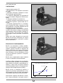
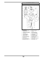
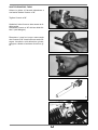
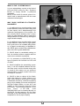
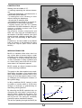
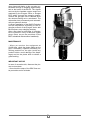
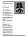
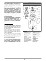
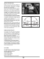
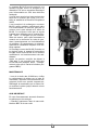
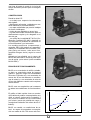
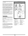
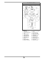
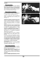
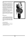
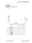
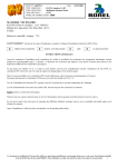
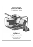
M.T.M. s.r.l.
Regione Oltre Tanaro, 6/B
I - 12062 - Cherasco (Cn)
Tel. ++39 0172 48681
Fax ++39 0172 488237
S
y
s
t
è
m
e
BLOS
BRC Gas Equipment
NT
PA
TE
BL
ED
OS
BRC
by
MTM
• Manuale Istruzioni •
• Instruction Manual •
• Mode d'emploi •
• Folleto de Instrucciones •
04.99
M.T.M. s.r.l.
COS’E’ IL “SYSTEME BLOS”?
Si tratta di una formidabile novità nel campo dei miscelatori GPL e metano per autotrazione. “Système BLOS”, o più semplicemente “BLOS”, è coperto da un brevetto
che si estende su scala mondiale.
BLOS è il frutto di anni di ricerca ed è realizzato con tecnologie d’avanguardia.
PERCHE’ “BLOS” ANZICHE’ UN MISCELATORE TRADIZIONALE?
1 - Un miscelatore tradizionale avente un
piccolo diametro interno funziona bene al
minimo ed a bassi regimi, ma penalizza le
prestazioni massime del motore. BLOS invece si comporta come un miscelatore di
grande diametro, capace di ridurre al minimo le perdite di carico, lasciando respirare
il motore a pieni polmoni.
1
2 - Un miscelatore tradizionale avente un
grande diametro interno funziona bene a
piena potenza, ma origina una carburazione instabile al minimo, vuoti nell’accelerazione, rischi di ritorni di fiamma. BLOS ovvia a tutti questi inconvenienti per la maggiore soddisfazione dell’utente finale.
3 - BLOS permette di risparmiare considerevolmente carburante. La sua eccellente
carburazione risponde alle più severe norme di emissione.
4 - E’ possibile installare BLOS su qualsiasi
tipo di vettura a iniezione alimentata sia a
GPL che a metano.
5 - BLOS semplifica il montaggio: può essere installato tra il debimetro a paletta ed il
corpo farfallato senza alcun apridebimetro
nè alcuna compensazione di pressione. Un
solo modello copre la gamma intera dei
veicoli.
6 - BLOS è capace di ridurre tutti i rischi di
ritorno di fiamma dovuti a una carburazione
imperfetta (è evidente che non potrebbe
mai porre rimedio ad un ritorno dovuto ad
una candela difettosa o ad una dispersione
di corrente proveniente dai cavi alta tensione o, ancora ad un impiego che arrivi fino
allo svuotamento completo del serbatoio
GPL). Il dispositivo di protezione del debimetro ø 70F-70M cod. 90AV99010033
può essere montato direttamente sul
BLOS. Allo scopo, limare il bordino di metallo della ghiera del corpo BLOS previsto
3
per il manicotto aria.
COSTRUZIONE
A partire dalla metà del ’97:
- una lavorazione che rispetta le tolleranze
più rigide,
- membrane rinforzate, realizzate in materiale resistente agli idrocarburi,
- un coperchio ridisegnato che permette di
lavorare evitando sfregamenti della membrana,
- il tubo gas realizzato in acciaio inox,
- il pistone bronzato internamente per uno
scorrimento regolare e senza usura sul tubo gas,
- un controllo qualità M.T.M. S.r.l. (Certificazione Qualità ISO 9001 ottenuta nel ’98)
che garantisce un prodotto affidabile sia nel
funzionamento che nella durata.
I modelli precedenti (componenti e centralina DEG 100) devono essere ricondizionati
dall’installatore della rete BRC (impiego pistone in bronzo, tubo acciaio inox, centralina Ecogas Junior) secondo la direttiva
BRC.
Inoltre sono state integrate sul corpo del
BLOS due borchie da filettare per vapori
d’olio ed aria minimo (raccordo a gomito
M14X1 della BRC).
2
PRINCIPIO DI FUNZIONAMENTO
BLOS è un miscelatore a orifizio variabile,
cioè un miscelatore capace di diventare
grande o piccolo secondo le esigenze del
motore. Equivale così ad un miscelatore
con meno di 10 mm di diametro in condizioni di minimo e ad un miscelatore di oltre
45 mm di diametro quando è completamente aperto.
BLOS crea un’aspirazione quasi costante
in tutte le condizioni di funzionamento.
BLOS, invece, in condizioni di minimo, è
capace di generare un’aspirazione in media maggiore da 20 a 50 volte, assicurando
una portata di gas assolutamente precisa.
Grafico Comparativo Mix Tradizionale - BLOS
∆p
4 0
Aspirazione Mix
Il grafico a fianco spiega come un miscelatore tradizionale produce un’aspirazione
molto debole al minimo (carburazione instabile) e molto forte al regime massimo
(causa di perdita di carico e conseguente limitazione del riempimento dei cilindri).
3
Mix Tradizionale
3 0
BLOS
2 0
1 0
0
Osservando l’esploso del BLOS si riconosce il corpo principale 6 nel quale scorre il
0
2
Min
4
4
6
8
Max
Portata Aria
pistone 18, guidato dal tubo 8. La membrana 19 è fissata al pistone per mezzo della
ghiera 20. La molla 22 spinge costantemente il pistone verso il basso.
Il flusso d’aria che passa attraverso il
BLOS (nel senso delle frecce) è sottoposto ad una caduta di pressione. Il differenziale di pressione che si crea, si propaga
sui due lati della membrana provocando
una forza che, risultando verso l’alto, produce l’apertura del pistone fino al conseguimento della posizione di equilibrio.
Si può quindi considerare che ad ogni valore di portata d’aria corrisponde una posizione del pistone ben definita.
In funzione della sua posizione, il pistone
scopre dunque una parte variabile della feritoia situata lungo il tubo 8, permettendo al
gas di uscire in proporzione alla portata necessaria.
SYSTEME BLOS
Bisogna osservare che:
a - un solo modello di BLOS si adatta alla
gamma intera dei veicoli. Il tubo acciaio
inox di adduzione gas è fornito con quattro
tipi di feritoie:
Feritoia E: portata normale (80% dei veicoli)
Feritoia D: portata maggiorata (15% dei
veicoli)
Feritoia A: portata super maggiorata (5%
dei veicoli)
Feritoia P: portata debole.
b - La posizione della feritoia può essere
regolata grazie alla ghiera 10 che permette
al tubo 8 di scorrere senza ruotare grazie
all’inserto a "M" 9. La ghiera 10 è l’equivalente della vite di registro tradizionale.
c - La vite 11 permette la regolazione della
carburazione al minimo, rendendo possibile
il passaggio d’un flusso supplementare di
gas attraverso l’orifizio che si trova sul fondo del corpo 6.
DENOMINAZIONE
1
CURVA INGRESSO GAS
2
OR2068 VITON
3
GHIERA D’ACCOPPIAMENTO
4
VITE TRILOBATA TE M4X10
5
COPERCHIO
6
CORPO PRINCIPALE
7
FASCETTA SERFLEX 70-90
8
TUBO BLOS IN INOX
RETTIFICATO
9
INSERTO A “M” BLOS
10 GHIERA REGOLAZIONE
PORTATA GAS
11 VITE REGOLAZIONE MINIMO
12 ANELLO DI TENUTA OR2012
VITON
13 OR3081 VITON
14 VITE APERTURA DISP.
EMERG. MANUALE
5
15 ANELLO DI TENUTA OR2015
NBR
16 CILINDRO DISP. EMERG.
MANUALE
17 RONDELLA ALLUMINIO
14X10X1
18 PISTONE BLOS CON GHIERA
IN RAME
19 MEMBRANA BLOS
20 GHIERA BLOCCAGGIO
MEMBRANA
21 VITE AUTOFILETTANTE
22 MOLLA
23 OR2050 VITON V.
24 OR2025 VITON V.
BLOS EVOLUTION
DENOMINAZIONE
1 CURVA INGRESSO GAS
2 OR2068 VITON
3 GHIERA D’ACCOPPIAMENTO
4 VITE TRILOBATA TE M4X10
5 COPERCHIO
6 CORPO PRINCIPALE
7 VALVOLA MINIMO
8 OR2012 VITON VERDE
9 FASCETTA 70-90
10 TUBO BLOS IN INOX RETT.
11 STAFFA SUPP.MOT. P.P.
12 INSERTO A “M”
13 NOTTOLINO DI CHIUSURA
14 MOLLA MOTORE P.P.
15 MOTORE P.P. CON ALETTA
6
16
17
18
19
20
21
22
23
24
25
26
27
28
29
30
VITE T.C.E.I. M5X25
OR3075
FILTRO IN FELTRO
OR2025 VITON VERDE
OR2081 VITON VERDE
VITE APERT. DISP. MAN.
OR2015 NBR
CILINDRO DISP. MAN.
PISTONE CON GHIERA
MEMBRANA BLOS
GHIERA BLOC. MEMBRANA
MOLLA CONICA
GHIERA PER ALBERO ROT.
OR15X1 NBR
VITE AUTOFIL. 2.9X6.5
INSTALLAZIONE DEL BLOS
BLOS è stato progettato per essere installato su vetture ad iniezione ma, grazie al pistoncino d’apertura a depressione, s’adatta
anche a quelle a carburatore.
Sulle vetture dotate di debimetro viene installato tra il debimetro ed il corpo farfallato, mentre su quelle senza debimetro il
BLOS deve essere collocato tra il filtro aria
ed il corpo farfallato.
Le frecce devono essere rivolte verso il
corpo farfallato. Inoltre bisogna verificare
che la feritoia del tubo ed i 2 fori del pistone
siano ben rivolti verso il motore.
La tubazione che porta il gas dal riduttore
al BLOS deve essere raccordata al gomito
1 e rimanere morbida per non creare tensione su questo raccordo in ottone. Non allungare inutilmente questa tubazione.
Su certe vetture si può facilmente tagliare il
manicotto originario per creare la sede per
il BLOS.
In altri casi è possibile utilizzare diversi tipi
di manicotti forniti dalla BRC, diritti o a gomito (60x70 o 70x70 o 80x70). Come nella
foto in alto, si consiglia di fissare direttamente sul Blos, lato motore, il salvadebimetro BRC 70x70 cod. 90AV99010033.
4
OK
OK
NO
NOTA IMPORTANTE
Un corretto serraggio delle fascette deve
garantire la tenuta di queste installazioni, in
particolare tra il BLOS ed il tubo d’adduzione gas.
E’ preferibile installare BLOS con la curva
di adduzione rivolta verso l’alto e con il motore passo a passo eventuale in basso, o
inclinato sopra il piano orizzontale come indicato nello schema.
La posizione con la curva verso il basso è
da evitare.
Il coperchio del BLOS è sigillato e non deve essere smontato, pena della scadenza
della garanzia (un montaggio scorretto potrebbe creare degli sfregamenti che pregiudicherebbero il buon funzionamento).
I TUBI
I tubi acciaio inox sono forniti con quattro tipi di feritoie che si adattano a diversi veicoli:
Feritoia E: portata normale
Feritoia D: portata maggiorata
Feritoia A: portata super maggiorata
Feritoia P: portata debole
BLOS è fornito con una feritoia D di serie.
7
OK
NO
SOSTITUZIONE DEL TUBO
Svitare la ghiera 10 facendo attenzione a
non lasciar cadere l’inserto a “M”.
Togliere l’inserto a “M”.
Sostituire il tubo 8 con un altro avente la feritoia scelta.
Rimontare l’inserto a “M” dal lato della feritoia !! (vedi disegno).
5
Rimontare i pezzi sul corpo osservando
che l’inserto a “M” rientri nella sua sede. Bisogna introdurlo nella direzione giusta,
spingere a fondo ed avvitare di circa un giro.
6
7
8
9
8
REGOLAZIONE
Regolazione del riduttore
La vite di regolazione del minimo del riduttore BRC deve essere avvitata a fondo
mentre la vite di regolazione della “sensibilità” deve mantenere la sua taratura originaria, con la sola eccezione dei veicoli a
carburatore e con l’avviamento diretto a
gas.
10
Regolazione vetture non catalitiche
Regolare la ghiera 10 verso la metà della
sua corsa (avvitare a fondo e svitare di 2
giri e oltre se necessario) (fig. 10).
Regolare la vite del minimo (avvitare a fondo e svitare di un giro e mezzo) (fig. 11).
Avviare il motore e commutare a gas. Utilizzando un analizzatore gas di scarico, fare
girare il motore a 3500 RPM e ricercare la
regolazione che permette d’ottenere nello
stesso tempo il massimo di CO2 ed il minimo di CO.
Regolare con estrema cura la ghiera 10
esattamente come una vite di regolazione
tradizionale (più si svita, più si dà gas). In
tutti i casi, uno spostamento di ± 2 mm del
tubo (2 giri della ghiera 10) modifica ampiamente l’arricchimento della miscela.
Regolare il CO - CO2 al minimo con la vite
del minimo (11) e ricontrollare a 3500 RPM
se è corretto.
Il Set 2000 potrà essere molto utile, particolarmente le prime volte, per acquisire
esperienza.
La vettura, una volta regolata correttamente, deve poter girare fino a 100-110 km/h
con una carburazione leggermente povera
(velocità costante) ma la carburazione deve arricchirsi rapidamente quando si
schiaccia a fondo sull’acceleratore. Ai regimi massimi il gas non deve mancare.
Perfezionare la regolazione del minimo
agendo sulla vite 11.
Per maggior sicurezza, ripetere l’operazione completa almeno due volte.
11
Regolazione vetture catalitiche
Il sistema BLOS Evolution è un perfezionamento del BLOS standard realizzato per i
veicoli catalitici.
Il sistema BLOS Evolution associato alla
centralina Ecogas Junior o Ecogas e al riduttore Fox è un complessivo omologato
per l’alimentazione a GPL dei veicoli catalitici.
Ha superato positivamente le prove più severe in materia di emissioni (CO, HC, NOx)
9
e risponde alla Direttiva Europea 96/69.
E’ costituito dal miscelatore BLOS a orifizio
variabile, perfezionato grazie alla motorizzazione del tubo gas con un motore passo
a passo adattato alla base del BLOS. I segnali emessi dalla sonda Lambda sono
analizzati dalla centralina Ecogas Junior
o Ecogas che, tramite il motore passo a
passo, controlla la salita o la discesa del tubo gas, quindi l’impoverimento o l’arricchimento della miscela. In modo permanente
ed automatico la carburazione dispone di
una miscela ottimale.
Un montaggio corretto del BLOS Evolution
e la regolazione secondo il manuale istruzioni Ecogas Junior associato con il BLOS
portano ad un funzionamento molto soddisfacente.
Dopo un primo controllo a 1000 km, si consiglia una revisione ogni 20.000 km (candele, filtri, come previsto nel libretto manutenzione programmata BRC).
MANUTENZIONE
- Alla revisione dei 20.000 km, verificare lo
scorrimento del pistone sul tubo. Se necessario nebulizzare esclusivamente del prodotto sbloccante (evitare qualsiasi prodotto
che potrebbe danneggiare la membrana)
sul tubo e far scorrere il pistone fino ad ottenere un buon funzionamento.
AVVISO IMPORTANTE
In caso di sporcizia eccessiva, smontare i
pezzi per pulirli.
- Controllare anche lo stato del salvadebimetro BRC e della sua paletta.
10
WHAT IS THE “SYSTEME BLOS”?
It is an extraordinary novelty in the field of
LPG and CNG mixers for cars. “Système
BLOS”, or simply “BLOS”, is patented
worldwide.
BLOS is the result of several years of research and is manufactured with the most
advanced technologies.
WHY “BLOS” INSTEAD OF A TRADITIONAL MIXER?
1 - A traditional mixer provided with a small
inside diameter works well while idling and
at slow speed, but it disadvantages the
maximum performances of the engine. On
the contrary BLOS behaves like a mixer
having a great diameter, able to reduce the
charge losses to a minimum, by leaving the
engine breathe deeply.
1
2 - A traditional mixer provided with a great
inside diameter works well at high speed,
but it gives rise to an unstable idling mixture, to gaps in accelerating, to flashback risks. BLOS gets round all these disadvantages to the user’s great satisfaction.
3 - BLOS allows a remarkable saving on
fuel. Its excellent mixture complies with the
most severe emission regulations.
4 - It is necessary to install BLOS on any
type of injection car fed both on LPG and
on CNG.
5 - BLOS simplifies the assembling operations: it can be installed between the bladed flow meter and the throttle body with
no need of flow meters nor any pressure
compensation. A single model covers the
full range of vehicles.
6 - BLOS is able to reduce all the flashback risks owing to a faulty mixture (it is
plain that it would be never able to remedy
a flashback caused by a defective sparking
plug or by a leakage of current coming from
the high voltage cables, or even by a use
leading to the complete emptying of the
LPG tank). The protection device of the
flow
meter
ø 70F-70M
code
90AV99010033 can be installed directly on
the BLOS. On this purpose, file the metal
flat band of the BLOS body ring nut contemplated for the air pipe coupling.
11
CONSTRUCTION
Starting from the middle of ’97:
- a working respecting the strictest tolerances,
- reinforced diaphragms, manufactured in a
hydrocarbon-proof material,
- a redesigned cover allowing to work
without rubbing the diaphragm,
- the gas pipe in stainless steel,
- the piston bronzed inside for a regular sliding and with no wear on the gas pipe,
- a quality control of M.T.M. S.r.l. (Quality
Certification ISO 9001 obtained in ’98) guarantees a reliable product both in its
working and in its life.
The previous models (components and
DEG 100 unit) must be reconditioned by
the installer of the BRC network (use of the
piston bronzed, stainless steel pipe, Ecogas Junior unit) according to BRC instructions.
Furthermore, we have added on the BLOS
body two bosses to be threaded for idling
oil and air vapors (BRC union elbow
M14X1).
2
WORKING PRINCIPLES
BLOS is a variable orifice mixer, that is to
say a mixer able to become large or small
according to the engine requirements. So it
is equivalent to a mixer having less than
10 mm of diameter in idling conditions and
to a mixer having more than 45 mm of diameter when it is completely opened.
BLOS creates an almost constant suction
in all the working conditions.
The graph on the side explains how a traditional mixer generates a very weak suction
while idling (unstable mixture) and a very
strong one at a high speed (cause of charge leakages and consequent limitation of
the cylinder filling).
By observing the BLOS exploded view, we
recognize the main body 6 where the piston 18 slides, guided by the pipe 8. The
diaphragm 19 is fixed to the piston through
the ring nut 20. The spring 22 constantly
pushes the piston towards the bottom.
The air flow passing through the BLOS (in
Comparative Graph between a Traditional Mixer and BLOS
∆p
4 0
Mixer suction
In idling conditions BLOS, instead, is able
to produce a suction which is 20-50 times
stronger on average, by guaranteeing an
absolutely precise gas flow.
3
Traditional Mixer
3 0
BLOS
2 0
1 0
0
0
2
Min
12
4
6
8
Max
Air Flow
the direction of the arrows) is subjected
to a pressure drop. The pressure differential created propagates on the two sides of
the diaphragm by provoking a resulting
upward force that produces the piston opening till the balance position is reached.
It is possible therefore to consider that a
well defined piston position corresponds to
every air flow value.
Depending on its position, the piston then
discovers a variable part of the slit situated
along the pipe 8 and enables the gas to come out in proportion to the necessary flow.
SYSTEME BLOS
It is necessary to remark that:
a - A single model of BLOS fits the full range of vehicles. The stainless steel gas feeding pipe is currently supplied with four types of slits:
Slit E: normal flow (80% of the vehicles)
Slit D: increased flow (15%of the vehicles)
Slit A: much increased flow (5% of the vehicles)
Slit P: weak flow
b - The position of the slit can be adjusted
thanks to the ring nut 10 which enables the
pipe 8 to slide without turning thanks to the
"M" piece 9. The ring nut 10 is the equivalent of the traditional adjusting screw.
c - The screw 11 allows the idling mixture
adjustment, enabling an additional gas flow
to pass through the orifice which is on the
bottom of the body 6.
DESIGNATION
1 GAS INLET ELBOW
2 OR2068 VITON
3 COUPLING RING NUT
4 M4X10 TRILOBED SCREW
5 COVER
6 MAIN BODY
7 CLAMP SERFLEX 70-90 H9
8 BLOS STAINLESS PIPE RECT.
9 “M” PIECE
10 GAS FLOW ADJUSTING
RING NUT
11 IDLING ADJUSTING SCREW
12 GAS RING OR2012
GREEN VITON
13 OR3081 VITON
13
14 EM.MANUAL DEVICE
OPENING SCREW
15 GAS RING OR2015 NBR
16 EM. MANUAL DEVICE
CYLINDER
17 ALUMINIUM WASHER
14X10X1
18 BLOS PISTON WITH COPPER
RING NUT
19 BLOS DIAPHRAGM
20 DIAPHRAGM LOCKING RING
21 SELF-THREADING SCREW
22 SPRING
23 OR2050 GREEN VITON
24 OR2025 GREEN VITON
BLOS EVOLUTION
DESIGNATION
1 GAS INLET ELBOW
2 OR2068 VITON
3 COUPLING RING NUT
4 TE M4X10 TRILOBED SCREW
5 COVER
6 MAIN BODY
7 IDLING ADJUSTING SCREW
8 OR2012 GREEN VITON
9 CLAMP 70-90
10 BLOS STAINLESS PIPE RECT.
11 STEPPING ENGINE SUPPORT
BRACKET
12 “M” PIECE
13 PAWL
14 STEPPING ENGINE SPRING
15 STEPPING ENGINE WITH TON
GUE
14
16
17
18
19
20
21
22
23
24
25
26
27
28
29
30
T.C.E.I. M5X25 SCREW
OR3075
FELT FILTER
OR2025 GREEN VITON
OR2081 GREEN VITON
MAN. DEVICE OP. SCREW
OR2015 NBR
MAN. DEVICE CYLINDER
PISTON WITH RING NUT
BLOS DIAPHRAGM
DIAPHRAGM LOCK.
RING NUT
CONICAL SPRING
ROT. SHAFT RING NUT
OR15X1 NBR
SELF-THREAD.SCREW
BLOS ASSEMBLY
BLOS has been devised to be installed on
injection cars but, thanks to the small vacuum opening piston, it also fits the carburettor ones.
On the vehicles provided with a flow meter,
BLOS is installed between the flow meter
and the throttle body. On the vehicles unprovided with a flow meter, it is installed
between the air filter and the throttle body.
The arrows must be turned towards the throttle body. It is furthermore necessary to
check that the pipe slit and the 2 piston holes are well turned towards the engine.
The pipe carrying gas from the reducer to
the BLOS must be jointed to the elbow 1
and remain soft not to produce tension on
thIS brass pipe fitting. Do not lengthen this
pipe pointlessly.
On some cars it is possible to cut easily the
original pipe coupling in order to create the
housing for the BLOS.
In other cases, it will be possible to use several types of pipe couplings supplied by
BRC, both straight and elbow (60x70 or
70x70 or 80x70). As per the above photo, it
is advisable to fix the BRC flow meter protection 70x70 code 90AV99010033 directly
on the Blos (engine side).
4
OK
OK
NO
IMPORTANT REMARK
A correct clamping shall guarantee the tightness of these installations, in particular
between the BLOS and the gas feeding pipe.
It is better to instal the BLOS with the feeding elbow turned upwards and with the
stepping engine (if any) down below, or inclined above the horizontal plane as per
the layout.
The position contemplating the elbow
downwards is to be avoided.
The BLOS cover is sealed and must not be
dismounted, to remain under warranty (an
incorrect assembly could generate rubbing
which would prejudice the good working).
THE PIPES
The stainless steel pipes are provided with
four types of slits allowing to fit the different
vehicles:
Slit E: normal flow
Slit D: increased flow
Slit A: much increased flow
Slit P: weak flow
BLOS is currently provided with a slit D.
15
OK
NO
REPLACEMENT OF THE PIPE
Unscrew the ring nut 10, making sure not
to let the “M” piece fall.
Remove the “M” piece.
Replace the pipe 8 with another one having
the slit chosen.
Remount the “M” piece from the slit side!!
(see the drawing)
5
Remount the pieces on the body by observing that the “M” piece re-enters its housing. It is necessary to introduce it in the right direction, to push to the bottom and to
screw of approximately a turn.
6
7
8
9
16
ADJUSTMENT
Reducer adjustment
The idling adjusting screw of the BRC reducer shall be screwed to the bottom and the
“sensitivity” adjusting screw shall maintain
its original setting, with the only exception
of the carburettor vehicles and cars starting
up directly on gas.
Non catalytic cars adjustment
Adjust the ring nut 10 towards the middle of
its stroke (screw to the bottom and unscrew
2 turns and more if necessary) (fig. 10).
10
Adjust the idling screw (screw to the bottom
and unscrew a turn and a half) (fig. 11).
Start the engine and change over to gas.
By using an exhaust gas analyser, let the
engine run at 3500 rpm and look for the
adjustment allowing to get the maximum
CO2 and the minimum CO in the same time.
Adjust carefully the ring nut 10 exactly like
a traditional adjusting screw (the more you
unscrew, the more you supply gas). In any
case, a shift of ± 2 mm of the pipe (2 turns
of the ring nut 10) greatly changes the mixture richness.
Adjust the CO - CO2 while idling through
the idling screw (11) and check again at
3500 rpm whether it is correct.
The Set 2000 shall be very useful, in particular the early times, to gain experience.
The car, once it is adjusted properly, shall
run up to 100-110 km/h with a slightly lean
mixture (constant speed) but the mixture
shall be quickly enriched while you step
completely on the accelerator. Gas mustn’t
fail at the highest speeds.
Improve the idling adjustment by acting on
the screw 11.
To be certain, repeat the complete operation at least twice.
11
Catalytic cars adjustment
The BLOS Evolution system is a completion of the standard BLOS manufactured
for the catalytic cars.
The BLOS Evolution system with the Ecogas Junior or Ecogas ECU and with the
Fox reducer is an approved unit for the
LPG feeding of the catalytic cars.
It has positively overcome the most severe
tests on emissions (CO, HC, NOx) and is in
accordance with the European Direction
96/69.
It consists of the variable orifice BLOS
17
mixer improved thanks to the gas pipe motorization through a stepping engine adapted on the basis of the BLOS. The signals
sent out by the Lambda oxygen sensor are
analysed by the Ecogas Junior or Ecogas
ECU which, through the stepping engine,
controls the gas pipe rise or descent, then
the mixture leaning out or enrichment. The
carburation has permanently and automatically an optimum mixture.
A correct installation of the BLOS Evolution
and the adjustment according to the instruction manual of the Ecogas Junior with
BLOS allow a very satisfying working.
After a first check at 1000 kms, it is advisable to overhaul it every 20.000 kms (spark
plugs, filters, as per the provisions of the
BRC scheduled maintenance handbook).
MAINTENANCE
- When you service the equipment at
20.000 kms, check the piston sliding on the
pipe. If necessary, vaporize exclusively unlocking products on the pipe (avoid any
product which could damage the diaphragm) and let the piston slide to obtain a
good working.
IMPORTANT NOTICE
In case of excessive dirt, dismount the pieces to clean them.
- Also check the state of the BRC flow meter protection and of its blade.
18
QU’EST QUE C’EST LE “SYSTEME
BLOS”?
Il s’agit d’une formidable nouveauté dans le
domaine des mélangeurs GPL et GNV
pour tous véhicules. “Système BLOS”, ou
plus simplement “BLOS”, est breveté dans
le monde entier.
BLOS est le résultat de plusieurs années
de recherche et il est réalisé avec les technologies les plus modernes.
POURQUOI “BLOS” AU LIEU D’UN MELANGEUR TRADITIONNEL?
1 - Un mélangeur traditionnel ayant un petit
diamètre intérieur marche bien au ralenti et
aux bas régimes, mais pénalise les performances maximum du moteur. Par contre,
BLOS se comporte comme un mélangeur
de grand diamètre, capable de réduire au
minimum les pertes de charge, laissant le
moteur respirer à pleins poumons.
1
2 - Un mélangeur traditionnel ayant un
grand diamètre intérieur marche bien en
pleine puissance, mais donne lieu à une
carburation instable au ralenti, à des trous
à l’accélération, à des risques de retour de
flamme. BLOS pallie tous ces inconvénients pour la plus grande satisfaction de
l’utilisateur.
3 - BLOS permet une remarquable économie de carburant. Son excellente carburation satisfait aux normes de rejets les plus
sévères.
4 - On peut installer BLOS sur n’importe
quel type de voiture à injection alimentée
aussi bien au GPL qu’au GNV.
5 - BLOS simplifie le montage: il peut être
installé entre le débitmètre à palette et le
papillon sans aucun ouvre-débimètre ni aucune compensation de pression. Un seul
modèle couvre la gamme des véhicules.
6 - BLOS est capable de réduire tous les risques d’explosion dûs à une carburation
imparfaite (il est évident qu’il ne pourrait jamais remédier à un retour dû à une bougie
défectueuse ou à une dispersion de courant venant des câbles haute tension, ou
encore à une utilisation allant jusqu’à la vidange complète du réservoir de GPL) Le
dispositif de protection du débitmètre ø
70F-70M code 90AV99010033 peut être
monté directement sur BLOS. A cet effet li19
mer le bourrelet de métal de la bague du
corps de BLOS prévu pour la durite.
CONSTRUCTION
Depuis la mi ’97:
- un usinage respectant les tolérances plus
strictes
- des membranes renforcées, réalisées
dans un élastomère résistant aux hydrocarbures
- un couvercle redessiné permettant un travail sans frottement de la membrane
- le tube gaz réalisé en acier inox
- le piston bagué bronze intérieurement
pour un coulissement régulier et sans usure sur le tube gaz
- un contrôle qualité des services M.T.M.
(Certification Qualité ISO 9001 obtenue
en’98) garantissent un produit fiable dans
le fonctionnement et dans la durée.
Les modèles antérieurs (pièces en composite et centrale DEG 100) doivent être reconditionnés par l’installateur du réseau
BRC (utilisation piston bagué, tube acier
inox, centrale Ecogas Junior) selon la directive BRC.
De plus il a été ajouté sur le corps de
BLOS deux bossages à tarauder pour vapeurs d’huile et air ralenti (raccord coudé
M14X1 de BRC).
2
PRINCIPE DE FONCTIONNEMENT
BLOS est un mélangeur à orifice variable,
c’est à dire un mélangeur capable de devenir grand ou petit selon les besoins du moteur. Il equivaut ainsi à un mélangeur de
moins de 10 mm de diamètre en conditions
de ralenti et à un mélangeur de plus de 45
mm de diamètre quand il est complètement
ouvert.
BLOS crée une aspiration quasi constante
dans toutes les conditions de fonctionnement.
BLOS, par contre, en condition de ralenti,
est capable d’engendrer une aspiration en
moyenne 20 à 50 fois plus forte, assurant
un débit de gaz absolument précis.
En observant l’éclaté du BLOS on recon-
Comparaison Mélangeur Traditionnel - BLOS
∆p
4 0
Aspiration Mélangeur
Le graphique ci-contre explique comme un
mélangeur traditionnel produit une aspiration très faible au ralenti (carburation instable) et très forte au régime maximum (diminution du taux de remplissage des cylindres).
3
Mélangeur Traditionnel
3 0
BLOS
2 0
1 0
0
0
2
Min
20
4
6
8
Max
Débit Air
naît le corps principal 6 dans lequel coulisse le piston 18, guidé par le tube 8. La
membrane 19 est fixée au piston par la bague 20. Le ressort 22 pousse constamment
le piston vers le bas.
Le flux d’air qui passe à travers BLOS
(dans le sens des flèches) est soumis à
une chute de pression. Le différentiel de
pression se propage alors sur les deux
côtés de la membrane en provoquant une
force résultante vers le haut, ce qui produit
l’ouverture du piston jusqu’à ce que la position d’équilibre soit atteinte.
On peut donc considérer qu’à chaque valeur de débit d’air correspond une position
du piston bien definie.
En fonction de sa position, le piston découvre donc une partie variable de la fente située le long du tube 8, ce qui permet au
gaz de sortir en proportion du débit nécessaire.
SYSTEME BLOS
Il faut remarquer que:
a - un seul modèle de BLOS convient pour
l’ensemble des véhicules. Le tube acier
inox qui introduit le gaz est livré avec quatre types de fente:
Fente E: débit normal (80% des véhicules)
Fente D: débit majoré (15% des véhicules)
Fente A: très gros débit (5% des véhicules)
Fente P: faible débit
b - la position de la fente peut être reglée
grâce à l’embout 10 qui permet au tube 8
de coulisser sans tourner par le biais de la
pièce "M" 9. Cet embout est l'équivalent de
la vis de réglage traditionelle.
c - La vis 11 permet le réglage de la carburation au ralenti, rendant possible le passage d'un flux supplémentaire de gaz à travers l'orifice qui se trouve sur le fond du
corps 6.
DENOMINATION
1 COUDE ENTREE GAZ BLOS
2 OR2068 VITON
3 BAGUE D’ENCLIQUETAGE
BLOS
4 VIS TRILOBEE TE M4X10
5 COUVERCLE BLOS
6 CORPS BLOS
7 COLLIER SERFLEX 70-90 H9
8 TUBE BLOS IX “D” RECTIFIE
9 PIECE INTERCALAIRE “M”
BLOS
10 BAGUE REGLAGE DEBIT GAZ
11 VIS REGLAGE RALENTI BLOS
12 BAGUE D’ETANCHEITE
OR2012 VITON V.
13 OR3081 VITON
21
14 VIS OUVERTURE DISP. URG.
MANUEL
15 BAGUE D’ETANCHEITE
OR2015 NBR
16 CYLINDRE DISP. URG. MAN.
17 RONDELLE ALUMINIUM
14X10X1
18 PISTON BLOS AVEC BAGUE
EN CUIVRE
19 MEMBRANE BLOS
20 BAGUE BLOCAGE
MEMBRANE
21 VIS AUTOFILETANTE
22 RESSORT
23 OR2050 VITON V.
24 OR2025 VITON V.
BLOS EVOLUTION
DENOMINATION
1 COUDE ENTREE GAZ
2 OR2068 VITON
3 BAGUE D’ENCLIQUETAGE
4 VIS TRILOBEE TE M4X10
5 COUVERCLE BLOS EVOL.
6 CORPS BLOS EVOLUTION
7 POINTEAU RALENTI BLOS EV.
8 OR2012 VITON VERT
9 COLLIER 70-90
10 TUBE BLOS IX “E” RECT.
11 BRIDE SUPP. MOT. P.P.
12 PIECE INTERCALAIRE “M”
13 GRIFFE FERMETURE
14 RESSORT MOTEUR P.P.
15 MOTEUR P.P. AVEC AILETTE
22
16
17
18
19
20
21
22
23
24
25
26
27
28
29
30
VIS T.C.E.I. M5X25
OR 3075
FILTRE EN FEUTRE
OR2025 VITON VERT
OR2081 VITON VERT
VIS OUVERT. DISP. MAN.
OR2015 NBR
CYLINDRE DISP. MAN.
PISTON AVEC BAGUE
MEMBRANE BLOS
BAGUE BLOC. MEMBRANE
RESSORT CONIQUE
BAGUE POUR ARBRE ROT.
OR15X1 NBR
VIS AUTOFIL. 2.9X6.5
INSTALLATION DU BLOS
BLOS a été conçu pour être installé sur
voitures injection, mais, grâce au petit piston d’ouverture à dépression, il s’adapte
également aux carburateurs.
Sur les voitures avec débitmètre, on l’installe entre le débitmètre et le papillon,
alors que s’il n’y a pas de débitmètre,
BLOS doit être placé entre le filtre à air et
le papillon. Les flèches doivent être
tournées vers le papillon. De plus, vérifier
que la fente du tube et les 2 trous du piston
soient bien retournés vers le moteur.
Le tuyau qui amène le gaz du vapo-détendeur au BLOS doit être raccordé au coude
1 et rester souple pour ne pas créer de
contrainte sur ce raccord en laiton. Ne pas
allonger ce tuyau inutilement.
Sur certaines voitures on peut facilement
couper la durite d’origine pour créer l’emplacement pour le BLOS.
Dans d’autres cas, on pourra profiter de
plusieurs types de durites de fourniture
BRC, droites ou coudées (60x70 ou 70x70
ou 80x70). Comme sur la photo ci-dessus il
est conseillé de fixer directement sur Blos,
côté moteur, le sauve débitmètre BRC
70x70 code 90AV99010033.
4
OK
OK
NON
REMARQUE IMPORTANTE
Un serrage correct des colliers doit garantir
l’étanchéité de ces montages, particulièrement entre BLOS et la pipe d’admission. Il
faut veiller à ce que ces raccords ne s’aplatissent pas à chaud, à l’aspiration.
BLOS fonctionne de préférence tête en
haut et moteur pas à pas en bas, ou encore incliné au-dessus de l’horizontal comme
indiqué sur le schéma.
La position tête en bas est à proscrire pour
un fonctionnement correct dans la durée.
Le couvercle du BLOS est scellé et ne doit
pas être démonté, sous peine de l’échéance de la garantie (un montage incorrect
pourrait créer des frottements qui nuiraient
au bon fonctionnement).
LES TUBES
Les tubes acier inox sont fournis avec quatre types de fentes qui permettent de satisfaire aux différents véhicules:
Fente E: débit normal
Fente D: débit majoré
Fente A: très gros débit
Fente P: faible débit
BLOS est livré d’origine avec une fente D.
23
OK
NON
REMPLACEMENT DU TUBE
Dévisser l’embout 10 en faisant attention à
ne pas laisser tomber la pièce à “M”.
Enlever la pièce “M”.
Remplacer le tube 8 par un autre ayant la
fente choisie.
Remonter la pièce à “M” du côté de la fente!!
5
Remonter les pièces sur le corps en observant que la “M” rentre dans son siège. Il
faut l’introduire dans la bonne direction,
pousser à fond et visser d’environ un tour.
6
7
8
9
24
REGLAGE
Réglage du vapodétendeur
Le pointeau de réglage du ralenti du vapodétendeur BRC doît être vissé à fond, alors
que la vis de réglage de la “sensibilité” gardera son étalonnage d’origine, à la seule
exception des véhicules à carburateur et
démarrant directement au gaz.
Réglage voitures non catalysées
Régler l’embout 10 vers la moitié de sa
course (visser à fond et dévisser 2 tours et
plus si besoin) (fig. 10).
10
Régler la vis du ralenti (visser à fond et dévisser un tour et demi) (fig. 11).
Démarrer le moteur et commuter au gaz.
En utilisant un analyseur de gaz d’échappement, faire tourner le moteur à 3500
RPM et rechercher le réglage qui permet
d’obtenir en même temps le maximun de
CO2 et le minimum de CO.
Régler finement l’embout 10 exactement
comme une vis de réglage traditionnelle
(plus on dévisse, plus on donne du gaz).
Dans tous les cas, un déplacement de ± 2
mm du tube (2 tours du bouton moleté 10)
modifie grandement la richesse du mélange.
Régler le CO - CO2 au ralenti par la petite
vis et recontrôler à 3500 tr/min si OK.
Le Set 2000 pourra être très utile, particulièrement les premières fois, pour acquérir
de l’expérience.
La voiture, une fois réglée correctement,
doit pouvoir rouler jusqu’à 100-110 km/h
avec une carburation légèrement pauvre
(vitesse constante) mais la carburation doit
s’enrichir rapidement dès que l’on appuie
au fond de l’accélérateur. Aux régimes
maximum le gaz ne doit pas manquer.
Perfectionner le réglage du ralenti en agissant sur la vis 11.
Pour plus de sûreté, recommencer l’opération complète deux fois de suite.
11
Réglage voitures catalysées
Le système BLOS Evolution est un perfectionnement du BLOS standard réalisé pour
les véhicules catalysés.
La motorisation du tube de gaz par un moteur pas à pas permet d’ajuster automatiquement en permanence le flux de gaz selon les indications de la sonde lambda transmises par la centrale Ecogas Junior ou
Ecogas.
Cet ensemble répond aux normes de rejet
les plus sévères.
25
Le système BLOS Evolution associé à la
centrale Ecogas Junior ou Ecogas et au
détendeur Fox est un ensemble homologué
pour l’alimentation au GPL des véhicules
catalysés.
Il a subi avec succès les épreuves les plus
sévères en matière de rejets (CO, HC,
NOx) et satisfait à la Directive Européenne
96/69.
Il est constitué du mélangeur novateur
BLOS à orifice variable, perfectionné grâce
à la motorisation du tube de gaz par un
moteur pas à pas adapté à la base de
BLOS. Les signaux émis par la sonde
Lambda sont analysés par la centrale Ecogas Junior ou Ecogas qui par l’intermédiaire du moteur pas à pas commande la
monteé ou la descente du tube de gaz,
donc l’apauvrissement ou l’enrichissement
du mélange. En permanence et automatiquement la combustion dispose d’un mélange optimal.
Un montage correct de BLOS Evolution et
le réglage selon le manuel d’instructions
Ecogas Junior avec BLOS de la centrale
conduisent à un fonctionnement très satisfaisant.
Après un premier contrôle de départ à
1000 kms, il est conseillé une visite tous
les 20.000 kms (bougies, filtres, ...vidange,
comme prévu par le carnet d’entretien programmé BRC).
MAINTENANCE
- Lors de la visite des 20.000 kms, vérifier
le coulissement du piston sur le tube. Si
nécessaire, vaporiser exclusivement du dégrippant (éviter tout produit risquant endommager la membrane) sur le tube et faire coulisser le piston jusqu’à obtenir un bon
fonctionnement.
AVIS IMPORTANT
En cas d’encrassement anormal démonter
les pièces pour les nettoyer.
- Contrôler également l’état du sauve-débitmètre BRC et de son volet.
26
¿QUÉ ES EL “SYSTEME BLOS”?
Es una formidable novedad en el sector de
los mezcladores GPL y GNC para todos
los coches. “Système BLOS” o, más sencillamente “BLOS”, es cubierto por una patente que se extiende a escala mundial.
BLOS es el resultado de años de investigaciones y se realiza con tecnologías de vanguardia.
¿PORQUÉ “BLOS” EN LUGAR DE UN
MEZCLADOR TRADICIONAL?
1 - Un mezclador tradicional con un diámetro interior pequeño marcha bien al ralentí
y a los bajos regímenes, pero perjudica el
rendimiento máximo del motor. En cambio
BLOS se comporta como un mezclador
con un gran diámetro, capaz de reducir al
mínimo las pérdidas de cargo, dejando el
motor respirar.
1
2 - Un mezclador tradicional con un gran
diámetro interior funciona bien con potencia máxima, pero produce una carburación
inestable al ralentí, vacíos en la aceleración, riesgos de contraexplosiones. BLOS
remedia todos estos inconvenientes para la
mayor satisfacción del cliente.
3 - BLOS permite ahorrar considerablemente carburante. Su excelente carburación se ajusta a las normas más severas
en materia de emisiones.
4 - Se puede instalar BLOS en cualquier tipo de coche a inyección alimentado sea
por GPL sea por GNC.
5 - BLOS simplifica el montaje: puede instalarse entre el debímetro de paleta y la
mariposa sin ningún abre-debímetro ni ninguna compensación de presión. Un solo
modelo se ajusta a la gama entera de los
vehículos.
6 - BLOS puede reducir todos los riesgos
de contraexplosiones debidas a una carburación imperfecta (es evidente que no podría nunca remediar una contraexplosión
debida a una bujía defectuosa o a una dispersión de corriente procedente de los cables alta tensión, o además a un empleo
que prevé hasta el vaciado completo del
tanque de GPL). El dispositivo de protección del debímetro ø 70F-70M cód.
90AV99010033 puede montarse directamente en el BLOS. A este propósito, hay
27
que limar el borde de metal de la virola del
cuerpo del BLOS previsto para el manguito
de aire.
CONSTRUCCION
Desde la mitad ’97:
- un trabajo que respecte las tolerancias
más rígidas,
- diafragmas reforzados, realizados en material resistente a los hidrocarburos,
- una tapa rediseñada que permite trabajar
sin frotar el diafragma,
- el tubo de gas realizado en acero inox,
- el pistón bronceado interiormente para un
deslizamiento regular y sin desgaste en el
tubo de gas,
- un control de la cualidad M.T.M. Srl (Certificación Cualidad ISO 9001 obtenida en
’98) aseguran un producto de confianza en
el funcionamiento y en la duración.
Los modelos anteriores (componentes y
centralita DEG 100) deben ser recondicionados por el instalador de la red BRC (empleo pistón en bronce, tubo acero inox,
centralita Ecogas Junior) según la norma
BRC.
Además se han añadido en el cuerpo del
BLOS dos tachuelas a enroscar para vapores de aceite y aire ralentí (unión acodada
M14X1 BRC).
2
PRINCIPIO DE FUNCIONAMIENTO
BLOS es un mezclador de orificio variable,
es decir un mezclador capaz de hacerse
grande o pequeño según las necesidades
del motor. Equivale así a un mezclador de
menos de 10 mm de diámetro en condiciones de ralentí y a un mezclador de más de
45 mm de diámetro cuando está completamente abierto.
3
BLOS crea una aspiración casi constante
en todas las condiciones de funcionamiento.
Gráfico Comparativo Mezc. Tradicional - BLOS
El gráfico al lado explica cómo un mezclador tradicional produce una aspiración muy
débil al ralentí (carburación inestable) y
muy fuerte al máximo de las revoluciones
por minuto (causa de pérdida de cargo y
consiguiente limitación del relleno de los cilindros).
Succión Mix
4 0
Mezclador Trad.
3 0
BLOS
2 0
1 0
BLOS, en cambio, en condiciones de ralentí, es capaz de engendrar una aspiración en media de 20 a 50 veces más fuer-
0
0
2
Min
28
4
6
8
Capacidad de Aire
Max
te, asegurando un flujo de gas absolutamente preciso.
SYSTEME BLOS
Observando la vista pormenorizada del
BLOS se reconoce el cuerpo principal 6
donde desliza el pistón 18, guiado por el
tubo 8. El diafragma 19 está fijado al pistón por la virola 20. El resorte 22 empuja
constantemente el pistón hacia abajo.
El flujo de aire que pasa a través del
BLOS (en el sentido de las flechas) está
sometido a una caída de presión. El diferencial de presión que se crea se propaga
en los dos lados del diafragma provocando
una fuerza resultante hacia arriba, lo que
produce la abertura del pistón hasta que se
alcance la posición de equilibrio.
Se puede entonces considerar que a cada
valor de flujo de aire corresponde una posición del pistón bien definida.
En función de su posición, el pistón descubre una parte variable de la tronera situada
a lo largo del tubo 8, lo que permite al gas
salir en proporción con el flujo necesario.
Hay que notar que:
a - un solo modelo de BLOS se aplica a todos los vehículos. El tubo acero inox que
introduce el gas se suministra con cuatro tipos de troneras:
Tronera E: flujo normal (80% de los vehículos)
Tronera D: flujo agrandado (15% de los
vehículos)
Tronera A: flujo muy agrandado (5% de los
vehículos)
Tronera P: flujo débil
b - la posición de la tronera puede ajustarse gracias a la virola 10 que permite al tubo 8 deslizar sin rodar gracias a la pieza
"M" 9. La virola 10 es el equivalente del tornillo de ajuste tradicional.
DENOMINACION
1 CURVA ENTRADA GAS
2 OR2068 VITON
3 VIROLA DE ACOPLAMIENTO
4 TORNILLO TE M4X10
5 TAPA
6 CUERPO PRINCIPAL
7 ABRAZADERA SERFLEX
70-90 H9
8 TUBO BLOS EN INOX RECT.
9 PIEZA “M”
10 VIROLA AJUSTE FLUJO GAS
11 TORNILLO AJUSTE RALENTI
12 ANILLO AISLADOR
OR2012 VITON V.
13 OR3081 VITON
14 TORNILLO ABERTURA DISP.
EM. MANUAL
c - El tornillo 11 permite ajustar la carburación al ralentí, haciendo posible el pasaje
de un flujo adicional de gas a través del orificio que está en el fondo del cuerpo 6.
29
15 ANILLO AISLADOR OR2015
NBR
16 CILINDRO DISP. EM.
MANUAL
17 ARANDELA ALUMINIO
14X10X1
18 PISTON BLOS CON VIROLA
EN COBRE
19 DIAFRAGMA BLOS
20 ANILLO SUJECION
DIAFRAGMA
21 TORNILLO
AUTOENROSCANTE 2.9X6.5
22 RESORTE
23 OR2050 VITON V.
24 OR2025 VITON V.
BLOS EVOLUTION
DENOMINACION
1
CURVA ENTRADA GAS
2
OR2068 VITON
3
VIROLA DE ACOPLAMIENTO
4
TORNILLO TE M4X10
5
TAPA
6
CUERPO PRINCIPAL
7
TORNILLO RALENTI
8
OR2012 VITON VERDE
9
ABRAZADERA 70-90
10 TUBO EN INOX RECT.
11 SOPORTE MOT. P.P.
12 PIEZA “M”
13 PERRO DE CIERRE
14 RESORTE MOTOR P.P.
15 MOTOR P.P. CON ALETA
30
16
17
18
19
20
21
22
23
24
25
26
27
28
29
30
TORNILLO T.C.E.I. M5X25
OR3075
FILTRO EN FIELTRO
OR2025 VITON VERDE
OR2081 VITON VERDE
TORNILLO AB. DISP. MAN.
OR2015 NBR
CILINDRO DISP. MAN.
PISTON CON VIROLA
DIAFRAGMA BLOS
ANILLO SUJ. DIAFRAGMA
RESORTE CONICO
ANILLO PARA ARBOL ROT.
OR15X1 NBR
TORNILLO AUTOENR.
INSTALACION DEL BLOS
BLOS ha sido concebido para ser instalado
en coches a inyección pero, gracias al pequeño pistón de abertura a depresión, se
aplica también a los a carburación.
En los coches con debímetro, se lo instala
entre el debímetro y la mariposa, mientras
que si no hay debímetro el BLOS debe posicionarse entre el filtro de aire y la mariposa.
Las flechas deben volverse hacia la mariposa. Además, hay que verificar que la tronera del tubo y los 2 agujeros del pistón
estén bien vueltos hacia el motor.
El tubo que trae el gas del reductor al
BLOS debe acoplarse a la curva 1 y quedarse suave para no crear tensión en la
unión en latón. No alarguen este tubo inútilmente.
En algunos coches se puede fácilmente
cortar el manguito originario para crear el
asiento para el BLOS.
En otros casos, se podrán utilizar diversos
tipos de manguitos BRC, derechos o acodados (60x70 ó 70x70 ó 80x70). Como en
la foto arriba, se aconseja fijar directamente en el Blos, lado motor, el salvadebímetro
BRC 70x70 cód. 90AV99010033
4
OK
OK
NON
NOTA IMPORTANTE
Un momento de torsión correcto de las
abrazaderas debe asegurar el sellado de
estas instalaciones, en particular entre el
BLOS y el tubo de alimentación gas.
Es preferible instalar el BLOS con la curva
de alimentación vuelta hacia arriba y con el
motor paso a paso (eventual) abajo, o inclinado sobre el plano horizontal, como indicado en el esquema.
Hay que evitar la posición con la curva hacia abajo.
La tapa del BLOS está sellada y no debe
desmontarse, so pena la pérdida de la garantía (un montaje incorrecto podría crear
frotamientos que perjudicarían el buen funcionamiento).
LOS TUBOS
Los tubos acero inox se suministran con
cuatro tipos de troneras que se aplican a
los diferentes vehículos:
Tronera E: flujo normal
Tronera D: fjujo agrandado
Tronera A: flujo muy agrandado
Tronera P: flujo débil
BLOS tiene de serie una tronera D.
31
OK
NON
SUBSTITUCION DEL TUBO
Desatornillen la virola 10 sin dejar caer la
pieza “M”.
Quiten la pieza “M”.
Substituyen el tubo 8 con otro con la tronera elegida.
¡¡Remonten la pieza “M” del lado de la tronera!! (vean el dibujo)
5
Remonten las piezas en el cuerpo observando que la “M” vuelva a entrar en su
asiento. Hay que introducirla en el sentido
correcto, empujar a fondo y atornillar de
una vuelta aproximadamente.
6
7
8
9
32
AJUSTE
Ajuste del reductor
El tornillo de ajuste ralentí del reductor
BRC debe atornillarse a fondo mientras
que el tornillo de ajuste de la “sensibilidad”
debe mantener su ajuste originario, con la
sola excepción de los vehículos a carburador y con arranque directo de gas.
Ajuste coches no catalíticos
Ajusten la virola 10 hacia la mitad de su recorrido (atornillen a fondo y desatornillen 2
2 vueltas y más si necesario) (fig. 10).
10
Ajusten el tornillo del ralentí (atornillen a
fondo y desatornillen de una vuelta y media) (fig. 11).
Arranquen el motor y conmuten a gas. Utilizando un analizador de gas de escape, accionen el motor a 3500 rpm y busquen el
ajuste que permite obtener en el mismo
tiempo el máximum de CO2 y el mínimum
de CO.
Ajusten finamente la virola 10 exactamente
como un tornillo de ajuste tradicional (más
se desatornilla, más se da gas). En todos
los casos, un desplazamiento de ± 2 mm
del tubo (2 vueltas de la virola 10) modifica
mucho el enriquecimiento de la mezcla.
Ajusten el CO - CO2 al ralentí con el tornillo
del ralentí (11) y vuelvan a controlar a
3500 rpm si es correcto.
El Set 2000 podrá ser muy útil, en particular las primeras veces, para adquerir experiencia.
El coche, cuando esté ajustado correctamente, debe marchar hasta 100-110 km/h
con una carburación algo pobre (velocidad
constante) pero la mezcla debe enriquecerse rápidamente cuando se apriete a fondo
el acelerador. Al máximo de las revoluciones por minuto, el gas no debe faltar.
Perfeccionen el ajuste del ralentí actuando
con el tornillo 11.
Para mayor seguridad, repitan la operación
completa al menos dos veces.
11
Ajuste coches catalíticos
El sistema BLOS Evolution es un perfeccionamiento del BLOS estándar realizado
para los vehículos catalíticos.
El sistema BLOS Evolution asociado a la
centralita Ecogas Junior o Ecogas y al reductor Fox es un conjunto homologado para la alimentación por GPL de los vehículos
catalíticos.
Ha sido sometido positivamente a los ensayos de emisión más severos (CO, HC,
33
NOx) y se ajusta a la Directiva Europea
96/69.
Es compuesto por el mezclador BLOS con
orificio variable, perfeccionado gracias a la
motorización del tubo de gas por un motor
paso a paso adaptado según el BLOS. Las
señales emitidas por la sonda Lambda son
analizadas por la centralita Ecogas Junior
o Ecogas que, por medio del motor paso a
paso, controla la subida o la bajada del tubo de gas, pues el empobrecimiento o el
enriquecimiento de la mezcla. Permanente
y automáticamente la carburación dispone
de una mezcla óptima.
Un montaje correcto del BLOS Evolution y
el ajuste con arreglo al folleto de instrucciones Ecogas Junior con BLOS producen un
funcionamiento muy satisfactorio.
Después de un control inicial a los 1000
kms, se aconseja un repaso todos los
20.000 kms (bujías, filtros, como previsto
en el folleto de manutención programada
BRC).
MANUTENCION
- Al efectuar el repaso de los 20.000 kms,
verifiquen el deslizamiento del pistón sobre
el tubo. Si necesario, pulvericen exclusivamente producto soltador (eviten cualquier
producto que podría perjudicar el diafragma) en el tubo y hagan deslizar el pistón
hasta que se alcance un buen funcionamiento.
AVISO IMPORTANTE
En caso de suciedad excesiva, desmonten
las piezas para limpiarlas.
- Controlen asimismo el estado del salvadebímetro BRC y de su paleta.
34
TA720001
M.T.M. s.r.l. Regione Oltre Tanaro 6/B 12062 - Cherasco (Cn) - Italy