1
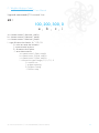
Adaptative Aggregation-Based Building System
An alternative to large scale 3D printing
MANUEL // MANUAL
© Charles BOUYSSOU // Oswald PFEIFFER // Mathieu VENOT
I : AABBS Theory (Explanation)
Article Théorique // Theorical Paper
« The Newtonian paradigm places the emphasis on external forces: gravity, natural
selection, the market, and so on. Taking nonlinearity into effect means we concentrate
more on the system: in evolution the developmental system of the organism, in economics
the nature of society and the people who make it up. It does not, as do relativity and
quantum mechanics, introduce entirely new scientific principles, but it can completely alter
the direction of our research all the same. »
- Peter Saunders (1)
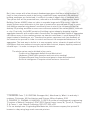
DEALING WITH THE UNPREDICTABLE
Dealing with unpredictable materials and emergent systems has been at the heart
of an important number of Architectural research projects over the past ten years. The
study of natural systems and how they could influence the way we design our own human
constructions brought a new paradigm to architecturaldesign: we do not have to design
everything in a top down approach, we can choose instead to declare a set of rules for a
system and then let the system itself determine its evolution. René Doursat, Hiroki Sayama
and Olivier Michel theorize the role of these potential meta-designers in A review of
morphogenetic engineering: “meta-designers will focus on creating local mechanisms that
allow small agents or components to assemble, coalesce, grow, or generate architectures
by themselves.” (2). It is obvious that the development of computer simulations has been a
major factor in that shift, allowing the interaction of a large amount of discrete elements,
often referred to as agents. Simulations based on this principle are commonly known
as Multi-agent Simulations, in which, because we only describe the rules that guide
individuals, we can only roughly predict the global behaviour of a swarm, thus the exact
position of an agent at a given moment in time, t, remains unpredictable. The emergent
complexity of such a stochastic approach generally offers a positive and a negative side
for architects and designers: a high degree of redundancy and self-organization on one
hand, but a problematic fabrication process due to the abstract geometry of the resulting
forms on the other. For these reasons, working directly on concepts such as redundancy,
self-organization and, as will be discussed here, aggregation, within the fabrication
process seems a more logical approach than designing using multi-agent systems and only
posthumously trying to recreate the form as accurate as possible. This last approach is in
fact highly contradictory and raises a lot of questions, such as; When should the simulation
be stopped? Do we have to build the resultant form exactly as-is? Is there a disparity
between the simulated material’s behaviour and the real one’s? Etc.
Recent research on large scale 3D printing (3) leads us to believe that additive
manufacturing will be an important breakthrough for architecture. This process shows a
lot of advantages from the removal of the need for formwork to an increased freedom in
the shapes’ definition (which together give rise to the possibility of optimizing the topology
of the elements produced) and eventually to an autonomy of the construction process.
© Charles BOUYSSOU // Oswald PFEIFFER // Mathieu VENOT
2
But it also comes with a few inherent disadvantages given that the printing process in
itself is slow, elements needs to be factory-made with heavy equipment, the machines’
building envelopes are limited and it is difficult to make it bigger once it has been built.
The system that will be presented here, referred to as Autonomous Aggregation-based
Building System (AABS), does not claim to overtake large scale 3D printing, it should
simply be seen as an alternative to this type of construction process and strives to prove
that additive manufacturing doesn’t necessarily have to mimic the increasingly familiar
desktop 3D printing workflow or even use continuous material like melted plastic, concrete
or clay. Practically, the AABS consists of building a given shape by dropping singular
aggregate elements with a cable robot. As we know, the unpredictable nature of aggregates
can induce errors in the creation process: an element could down, it could bounce off its
target instead of hooking on, etc. Therefore the system requires a real-time feedback of
the construction process in order to control and correct the unexpected behaviour of the
aggregates. The best way to do this is to use computer vision, a branch of weak artificial
intelligence that uses sensors to acquire optical data (colours, shapes, depth by means of
infrared rays...) in order to interpret its direct environment.
The whole system can be divided in four parts:
- Construction (Aggregate definition and fabrication)
- Hardware (Cable robot operation and instruction sending)
- Software (General User Interface and generic shape discretization)
- Artificial intelligence (Computer vision and error correction)
__________
1. SAUNDERS Peter T, DI CRISTINA Giuseppa (dir), «Nonlinearity. What it is and why it
matters», Chichester, AD Architecture and Science, Wiley-Academy, 2001
2. DOURSAT, R., SAYAMA, H. & MICHEL, O. (2013) A review of morphogenetic engineering.
“Frontiers of Natural Computing” (FNC 2012) Special Issue. Lones, M., Tyrrell, A., Stepney,
S. & Caves, L., eds. Natural Computing 12(2): 517-535, p.531
3. For an example see: Yingchuang New Materials, the chinese company that printed 10
houses in a day using large scale concrete printers.
I : AABBS Theory (Explanation)
Article Théorique // Theorical Paper
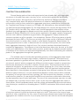
CONSTRUCTION (AGGREGATES)
Several design and architectural experiments have already dealt with aggregate
structures in the past few years, serving, in fact, as the starting point for the broader
scope of this project. Among others, Karola Dierichs and Achim Menges provided a
very complete work about the physical behaviour of cohesion-based elements at a
microscopic scale for their research on aggregate structures conducted at the Institute
for Computational Design, University of Stuttgart (4). Minimaforms also worked on lasercut and hand projected aggregates for the stage design of a concert during summer 2014
(5). Another work, that uses clay, offers a very similar approach in the machine vision
feedback loop and aggregation-based construction system: Remote material deposition by
Gramazio & Kohler Research (6). As the system exposed in this paper needs to be generic,
such as most additive manufacturing processes, the aggregates’ shape, material, and
cohesion method can all be variable. Just as desktop, filament 3D printers were originally
developed for basic ABS or PLA but can actually use a large variety of different filaments
from tensile plastic to carbon fibre, wood or metal based composites. Nevertheless, for
testing purposes and in order to demonstrate the concept of the system, the robot needs
basic aggregate elements to deal with so a first solution has been developed based on
mechanical aggregation. The different criteria that have been taken into account so far deal
mainly with optimization of the fabrication process: producing the highest possible number
of modules at the lowest cost and machining/assembly time while maximizing the cohesion
power of the aggregates through their geometry.
The method used to find the best possible geometry of the aggregates was based
on a fitness analysis through a high number of physical simulations. Three families of
wireframe parametric geometries (star-like forms, pyramid-like shapes and branch-like
structures), each of which contained six different variations were tested in a proprietary
benchmark, developed in Unity3D, to define a fitness value. This benchmark ran in two
sequential iterations, ten generations of ten modules dropping for a first, then a hundred
generations of fifty modules for the second iteration. Once the two best module options
were identified, a second phase consisted of designing three different modules (for three
different types of density) in a more detailed way based on these results which revealed
the potency of using a hook and loop typology, just like hook and loop fastener, in order to
maximize the cohesion. A new physical simulation set was then conducted to determine
the best possible size of hooks and loops. The aim of this second phase was also to make
the shapes easy to produce with a laser-cutter. In the end, each aggregate was made of
three planar, slotted cardboard pieces and the cutting and assembling process took about
two minutes per module for a bounding box of 15x15x15 centimetres and minimal material
costs.
This fast and cheap solution served well for testing purposes but can’t be considered
a long term material to build architectural objects in itself. There are in fact a very large
amount of other possibilities for this, some of which have already been tested like using the
aggregation as a substructure for a lycra-epoxy shell that can even be reinforced with glass
© Charles BOUYSSOU // Oswald PFEIFFER // Mathieu VENOT
4
fibres, while others need more financial investment and research into their application but
possess a real construction potential, such as metal aggregates as a support for shotcrete.
Although these two options are based on mechanical aggregation, chemical aggregation
could be another interesting possibility because it would not require any subsequent
solidification.
__________
4. See the two following papers: DIERICHS Karola, MENGES Achim, Aggregate structures.
Material and machine computation of designed granular substances, Institute for
Computational Design, University of Stuttgart, John Wiley & Sons, 2012 DIERICHS Karola,
MENGES Achim, Material Computation in Architectural Aggregate Systems, Institute for
Computational Design, University of Stuttgart, ACADIA 2010
5. This project can be seen on the Minimaforms website : http://minimaforms.com/
imogenheap/
6. This project can be seen on the Gramazio & Kohler Research website : http://
gramaziokohler.arch.ethz.ch/web/e/lehre/276.html
I : AABBS Theory (Explanation)
Article Théorique // Theorical Paper
HARDWARE (ROBOTICS)
The cable robot that is being developed for dropping the aggregates offers several
important advantages compared to a regular three axis CNC. For this particular case,
the research has been focused on portability, modularity and compactness. All the
mechanical parts are grouped inside the robot’s head, that way setting up the system in
any environment is incredibly easy: you just need to attach the three cables to three points
in space (these three points form a triangle that defines the system’s working space). The
modularity also comes from the fact that there’s some space remaining on the robot’s head,
allowing the user to add three more cables to improve the robot’s precision and stability if
needed.
The fact that we can arbitrarily define the anchor points and can ignore cable
overlay (a problem that plagues cable robots where the cable winds onto itself causing
massive imprecision by effectively changing the spindle’s radius) is afforded by a servitude
algorithm that allows us to avoid absolute coordinates.
What this means is that the robot’s operations are controlled by a feedback loop that
determines the difference between the desired action and the actual one. This workflow
uses machine vision and is very close to the construction correction routine that was
briefly outlined earlier, the only difference here resides in the fact that the vision is not
based on the same algorithm. Here, the space and the position of the robot’s head are
acquired using markers, specific patterns that looks a bit like QR codes.
In order to pick up the aggregates, the robot’s pendulous head uses a simple claw
at its bottom that is ample thanks to the aggregates’ own hooks. It will then drop them
one by one, from the bottom to the top. The electronics parts are controlled by an opensource Arduino PCB, so instructions for the motors can be sent using Arduino software or
Processing, which, as we will describe in the next section, has its own advantages.
SOFTWARE (GENERAL USER INTERFACE)
In 3D printing, the discretization of a shape and its conversion to instructions for the
printer is provided by a software called a slicer. As the name suggests it slices a 3D model,
typically a .stl file, into a G-code-like file. The user then has two options to execute this
code, either transferring this file to the printer via an external storage device or connecting
a computer directly to the printer to read the file in real time. Recently, a new generation
of slicers have appeared called voxelizers, because the discretization of the 3D object
file works with voxels (3D pixels) instead of slices. It is an interesting approach, because
the printer deals with a three dimensional array of small blocks of material, which makes
multi-material model fabrication much more viable.
The AABS needs a constant feedback because it’s a dynamic system that can’t
© Charles BOUYSSOU // Oswald PFEIFFER // Mathieu VENOT
6
work with a simple series of linear instructions. Because of that, a software able to deal
with real-time environment data acquired from computer vision needs to stay connected
to the robot. As it also deals with aggregates of different materials, sizes and densities
that are potentially customizable, it was chosen to encode a specific voxelizer software
on Processing able to, first of all, guide any user through the different discretization steps,
material assignment, and construction settings, then run the robot in real time while
returning information and statistics about the construction process to the user. This also
allows him to see the disparity between the theoretical model (the system’s production
target) and the current state of the construction process.
Different voxelization strategies are established, for example, it can be based on
a recursion using three sizes of modules, that way the centre of the shape can be filled
with large aggregates while the borders can be built with smaller modules, giving a higher
resolution finish. Another possibility is to use bigger aggregates at the bottom of the
construction, strengthening its base, and smaller aggregates at the top or for crossings.
ADAPTATIVE (COMPUTER VISION)
At the heart of the AABS resides the construction process’s artificial intelligence. So
far, it is able to detect and deal with three different error types :
(1) An aggregate can fall, miss or rebound off its target instead of hooking on, and
stay isolated on the floor.
(2) One or several aggregates can fall, or the target spacing generated by the initial
shape discretization can be too wide for the chosen aggregate density, resulting in a lack of
density at some points of the structure compared to the ideal simulation.
(3) The target spacing generated by the initial discretization can be too dense for
the chosen aggregate density, resulting in emergent artefacts due to a too high amount of
modules dropped at the same place.
The computer vision uses two Kinect cameras to scan the environment in real time, this
generates coloured points in space, resulting from the interpolation of the camera colors
and of the distances given by the infrared ray casting. Every n aggregates dropped, the
software will isolate the scanned aggregates using their colour (the best way to do that
is to use the equivalent of a chroma key) before comparing their actual positions to their
theoretical positions to solve errors (2) and (3). Obviously, it is nigh-on impossible to
identify single elements from a collection of aggregates, so in order to determine if a target
has been missed (error type 2), the software checks its distance to the closest scanned
point of the ensemble before filling the structure’s holes. We use the same process for the
error type 3, but this time the software is also checking the heights of the scanned points
to know if some elements have been dropped above the highest targets reached so far, if
I : AABBS Theory (Explanation)
Article Théorique // Theorical Paper
so, the surrounding targets will be consider as reached already. To solve error type 1, the
robot needs to detect and grab one particular module, for which we use a Blob Detection
algorithm, allowing the program to identify an isolated object by its outline. After checking
if this aggregate is reachable (if the cables are not going to intersect the structure), the
robot will be able to grab it and reuse it.
DEVELOPMENT
Of course, the AABS detailed here can be seen as a simple proposal to deal with
unpredictable material constructions. It was never desired that any of the four subresearches that have been presented here be irreplaceable: the aggregates could have
different shapes and properties, the cable robot could be replaced by drones or by six-axis
robots, the shape discretization could be done with alternative strategies, the feedback loop
could use other types of sensors etc. Diversity is in fact encouraged as it keeps pushing
this approach further.
The AABS is an interesting proposal because it works in its entirety and therefore
proves that it is possible, here and now, to build complex architectural objects at a large
scale based on unpredictable materials and local interactions: the user feeds the software
some simple rules (an overall 3D shape, a discretization strategy, a variety of aggregates...)
and then the system builds on its own, calibrating its actions on a physical feedback and
thus allowing the emergence and self- organization of the growing structure.
© Charles BOUYSSOU // Oswald PFEIFFER // Mathieu VENOT
8
Adaptative Aggregation-Based Building System
An alternative to large scale 3D printing
AABBS SLIC3R (TOOLPATH SOFTWARE)
© Charles BOUYSSOU // Oswald PFEIFFER // Mathieu VENOT
10
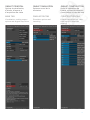
A : AABBS Slic3r (Toolpath Software)
Manuel d’Utilisateur // User Manual
Manuel //Manual
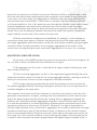
1. Import d’un mesh à l’ouverture
Mesh importation at the software opening
2. Réglage de l’espacement des cibles
Setting targets spacing
Equipement // Equipment :
- Processing 3.0a5
Processing 3.0a5
- Java 1.6
Java 1.6
3. Acquisition des cibles
Targets acquisition
11
A : AABBS Slic3r (Toolpath Software)
Manuel d’Utilisateur // User Manual
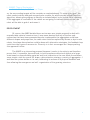
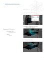
4. Correction éventuelle des cibles mal
positionnées
Possible correction of the bad targets
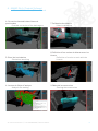
7. Calibration des kinects
Kinects calibration
5. Envoi de la simulation
Simulation launching
8. Définition d’une couleur à détecter avec les
kinects
Definition of a color to track with the kinects
6. Lecture du fichier d’analyse
Analysis file reading
9. Début de la construction
Starting the construction
© Charles BOUYSSOU // Oswald PFEIFFER // Mathieu VENOT
12
ONGLET PRINCIPAL
ONGLET SIMULATION
ONGLET CONSTRUCTION
Options de visualisation,
d’échelle, d’exports et
d’acquisition des cibles
Options et envoi de la
simulation
Outils de calibration des
kinects, utilitaire de sélection
d’une couleur et envoi du code
MAIN TAB
SIMULATION TAB
CONSTRUCTION TAB
Visualization, scaling, export
options and targets acquisition
Simulation options and
launching
Kinects calibration tool, color
tracking utility and code
sending
13
Adaptative Aggregation-Based Building System
An alternative to large scale 3D printing
WIREBOT (CABLE ROBOT)
© Charles BOUYSSOU // Oswald PFEIFFER // Mathieu VENOT
14
B : WireBot (Cable Robot)
Manuel d’Utilisateur // User Manual
Réglages // Settings :
Equipement // Equipment :
- Moteurs NEMA 2400 N-cm
NEMA Steppers 2400 N-cm
(http://www.selectronic.fr/c/coffretsdissipateurs-quincaillerie/moteurs/pas-a-pasbipolaires/moteur-pas-a-pas-modele-pap-20.
html)
- Controleurs Moteurs 6A
Stepper Drivers 6A
(http://www.selectronic.fr/c/robotiquemoteurs-accessoires/control-modules/
commandes-de-moteurs-pas-a-pas/modulede-commande-pour-moteur-pas-a-pascw8060.html)
- Alimentation Variable 24V
24V Variable Power Supply
(http://www.selectronic.fr/alimentationvariable-a-decoupage-0-a-30v-0-a-20a.html)
- Profilés ELCOM
ELCOM Structure Frame
- Mécanique HPC
HPC Mechanics
- Moteurs NEMA 2400 N-cm
Pair de cables 1 = Vert & Rouge
Pair de cables 2 = Bleu & Jaune
NEMA Steppers 2400 N-cm
Cables pair 1 = Green & Red
Cables pair 2 = Blue & Yellow
- Controleurs Moteurs 6A
Microstep = 1/2
Courant de sortie = 3,71A
Stepper Drivers 6A
Microstepping = 1/2
Current Output = 3,71A
- Alimentation Variable 24V
Voltage de sortie = 24V
Courant de sortie = 6A
24V Variable Power Supply
Voltage Output = 24V
Current Output = 6A
- Cable acier 2mm
Steel cable 2mm
- Démultiplication 2:1
Ratio 2:1
15
B : WireBot (Cable Robot)
Manuel d’Utilisateur // User Manual
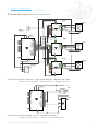
Schémas éléctriques // Electric schematics :
Contrôle des moteurs (Arduino - Controleurs Moteurs - Moteurs pas à pas)
Motor control (Arduino - Stepper Drivers - Stepper Motors)
Contrôle de la pince (Arduino - Servo - Recepteur optionel)
Gripper control (Arduino - Servo - Optional Receiver)
© Charles BOUYSSOU // Oswald PFEIFFER // Mathieu VENOT
16
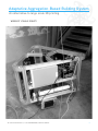
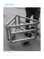
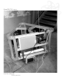
Montage de la structure // Structure assembly :
Modular
structure
Power and
control box
Winding
system
Motor
Vue éclatée
Exploded view
B : WireBot (Cable Robot)
Manuel d’Utilisateur // User Manual
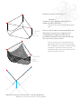
Espace de travail // Workspace :
Unreachable area
Reachable area
Espace utile atteignable du WireBot
WireBot reachable area
© Charles BOUYSSOU // Oswald PFEIFFER // Mathieu VENOT
18
Espace de travail // Workspace ::
- Variables
Charge du robot, puissance des moteurs,
rapport de démultiplication.
Charge of the robot power motor, gear ratio.
Potential
area
307 m3
Pour le robot à câbles, la zone exploitable est
définie par la tension et la longueur du fil.
L’évaluation de l’espace est faite par un
procédé stochastique évalué par la méthode
des trois forces concurrentes.
Potential
area
143 m3
Méthode des forces concourantes, “statique graphique”
Method of concurrent forces “static graphic”
For the wirebot, the workable area is defined by the wire tension and length.
The evaluation of space is made using a
stochastic method to determine the reachable space with the method of the three concurrent forces.
X_ : Chapter
Proposition pour le controle // Control proposal :
Anchor point 1
L1
l1
Pos P
Pos P+1
Cam 1
© Charles BOUYSSOU // Oswald PFEIFFER // Mathieu VENOT
20
Proposition pour le controle // Control proposal :
Anchor point 2
- Variables
Vitesse d’enroulement maximum permise au
robot.
Vmax
Relation d’asservisement proposée :
Slaving relationship :
L1 - L2 = ∆L
l1 - l2 = ∆l
L2
V∆x = ∆x/Vmax
l2
if (dist(Pos P , Pos P+1) ≈ 0){
Vmax = 0
}
Cam 2
- Principe
L’acquisition rapide des caméras 3D (25
FPS) permet de positionner précisément le
robot dans l’espace de manière relative à son
environnement par l’application continue de la
boucle d’asservissement.
- Principle
The rapid acquisition of 3D cameras (25 FPS) can precisely set the robot in the space relativly to its environment
by the continuous application of the control loop feedback.
21
B : WireBot (Cable Robot)
Manuel d’Utilisateur // User Manual
Vues 3D // 3D views :
Vue d’un cadre type
Frame type view
© Charles BOUYSSOU // Oswald PFEIFFER // Mathieu VENOT
22
Vues 3D // 3D views :
Vue d’un cadre type
Frame type view
Adaptative Aggregation-Based Building System
An alternative to large scale 3D printing
WIREBOT (ARDUINO CODE)
© Charles BOUYSSOU // Oswald PFEIFFER // Mathieu VENOT
24
C : WireBot (Arduino Code)
Manuel d’Utilisateur // User Manual
Réglages // Settings :
- Libraries
AccelStepper (controle moteurs)
Servo (controle pince)
VirtualWire (optionel, controle sans fil)
Libraries
AccelStepper (stepper control)
Servo (gripper control)
VirtualWire (optional, wireless control)
Equipement // Equipment :
- Arduino DUE
Arduino DUE
- Arduino IDE 1.6.4
Arduino IDE 1.6.4
- Pins
2 = Step M1
3 = Step M2
4 = Step M3
5 = Direction M1
6 = Direction M2
7 = Direction M3
Pins
2 = Step M1
3 = Step M2
4 = Step M3
5 = Direction M1
6 = Direction M2
7 = Direction M3
- Variables
BUFFSIZE = 256
Serial.begin = 9600 (vitesse baudrate)
Variables
BUFFSIZE = 256
Serial.begin = 9600 (baudrate speed)
25
C : WireBot (Arduino Code)
Manuel d’Utilisateur // User Manual
Ligne de commande // Command line :
ex :
100, 200, 300, 0
a , b , c , i
a = vitesse moteur 1 (decimal , pas/s)
b = vitesse moteur 2 (decimal , pas/s)
c = vitesse moteur 3 (decimal , pas/s)
i = type d’instruction (entier, 0 / 1 / 2 / -1)
0 : mise en route des moteurs
1 : ouverture de la pince
2 : fermeture de la pince
-1 : arret des moteurs
a = speed motor 1 (float, step/s)
b = speed motor 2 (float, step/s)
c = speed motor 3 (float, step/s)
i = instruction type (integer, 0 / 1 / 2 / -1)
0 : motors run
1 : gripper opening
2 : gripper closing
-1 : motors stop
© Charles BOUYSSOU // Oswald PFEIFFER // Mathieu VENOT
26
Adaptative Aggregation-Based Building System
An alternative to large scale 3D printing
AGGREGATED STRUCTURE (MODULE CONSTRUCTION)
© Charles BOUYSSOU // Oswald PFEIFFER // Mathieu VENOT
28
D : Aggregated Structure (Module Construction)
Manuel d’Utilisateur // User Manual
Réglages // Settings :
Equipement // Equipment :
- Programme
-Software
Processing IDE :
import toxi.geom.*;
import toxi.geom.mesh.*; // GEOMETRIE
import peasy.*; // DISPLAY
import java.awt.Frame; // GUI
import java.awt.BorderLayout; // GUI
import controlP5.*; // GUI
import SimpleOpenNI.*; //SENSOR
import OpenCV.*; //VISION MACHINE
import processing.serial.*; //
HARDWARE COMMUNICATION
- Matériel
-Hardware
Robot ABB 1600 145
pince schunk avec préhension
2 kinect (Xbox)
ABB Robot 1600 145
Schunk gripper with gripping
Kinect 2 (Xbox)
- Eléments de construction
-Building elements
Module en carton
Époxy et fibre de verre
Lycra
Cardboard module
Epoxy and fiberglass
Lycra
- Programme
-Software
Les variables sont :
vitesse de déplacement
Domaine de vision, colorimétrique, spatiale
Domaine de sensibilité a l’erreur
Méthode de choix des modules
Méthode de choix des cibles a atteindre
Variables are:
Speeding
Field of vision, color, space
Sensitivity field error
Method of selection of modules
Method of selection of targets to be achieved
- Robot
-Robot
Le système de positionnement peut être
n’importe quel utilitaire de déplacement à 2
axes ou plus.
Pour les tests effectués :
- Robot a cables
- ABB 1600 145
The positioning system may be any displacement utility with 2 axes or
more.
To perform the tests:
- Cables robot
- ABB 1600 145
- Eléments de construction
--Building elements
modules en carton
- 3 typologies de modules
- 5 tailles de modules
Cardboard module
- 3 module types
- 5 module sizes
29
X_ : Chapter
© Charles BOUYSSOU // Oswald PFEIFFER // Mathieu VENOT
30
D : Aggregated Structure (Module Construction)
Manuel d’Utilisateur // User Manual
Manuel // Manual :
- Robot
- Robot
mise sous tension
calibration si nécessaire
mise en communication du robot avec
l’ordinateur
Turning trying
Calibration (if necessary)
Communication of the robot with
the computer
- Environement
- Environment
Préparation du rack a modules
Modules rack preparation
- Programme
- Program
Préparation du model 3D
3D model preparation
- Construction
- Construction
Mise en route de la communication entre la
machine et le programme
Initialization of the communication
between the machine and the program
31
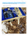
Adaptative Aggregation-Based Building System
An alternative to large scale 3D printing
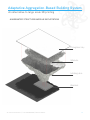
AGGREGATED STRUCTURE (MODULE EXPLOITATION)
Plexiglass tray
Modules
Holding skin
Bedrock
© Charles BOUYSSOU // Oswald PFEIFFER // Mathieu VENOT
32
D : Aggregated Structure (Module Exloitation)
Manuel d’Utilisateur // User Manual
Equipement // Equipment :
- Matériel
-Hardware
Empilement de modules mis en forme
Époxy et fibre de verre
Fondations (béton)
Plateaux (Verre, PMMA)
Module pile shaped
Epoxy and fiberglass
Foundation (concrete)
Boards (glass, PMMA)
Construction // Construction :
- Temps de construction
-Construction time
mise en forme des modules :
modules shaping :
45 min
Renforcement de la coque :
Shell reinforcement:
2h
Ancrage et fabrication de la dalle :
Slab fabrication and anchoring:
2h
33