1
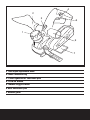
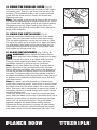
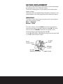
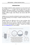
24
SAFETY AND OPERATING MANUAL
Original instructions
PLANER 900W
TTB291PLN
Congratulations on your purchase of a
power tool from Titan Power Tools
(UK) Ltd. We want you to continue getting the best performance from it so this
handbook includes information on safety, handling and care. Please retain this
handbook in case you need to refer to any of the information in the future.
Your
power tool comes with a 24-month guarantee, so should it develop
a fault within this period contact your retailer.
GUARANTEE
This
product carries a guarantee of 24 months. If your product develops a fault
within this period, you should, in the first instance contact the retailer where the item was
purchased.
This guarantee specifically excludes losses caused due to:
- Fair wear and tear
- Misuse or abuse
- Lack of routine maintenance
- Failure of consumable items (such as batteries)
- Accidental dammage
- Cosmetic damage
- Failure to follow manufacturer’s guidelines
- Loss of use of the goods
This guarantee does not affect your statutory rights. This guarantee is only valid in the
UK.
For any enquiries relating to the guarantee please refer to your retailer.
GENERAL SAFETY INSTRUCTIONS
WARNING! Read all safety warnings designated by the symbol
all instructions.
and
WARNING! Read all safety warnings and all instructions. Failure to follow the
warnings and instructions may result in electric shock, fire and/or serious injury.
Save all warnings and instructions for future reference.
The term "power tool" in the warnings refers to your mains-operated (corded) power tool or
battery-operated (cordless) power tool.
1. Work area safety
a. Keep work area clean and well lit. Cluttered or dark areas invite accidents.
b. Do not operate power tools in explosive atmospheres, such as in the
presence of flammable liquids, gases or dust. Power tools create sparks which
may ignite the dust or fumes.
c. Keep children and bystanders away while operating a power tool.
Distractions can cause you to lose control.
2. Electrical safety
a. Power tool plugs must match the outlet. Never modify the plug in any way.
Do not use any adapter plugs with earthed (grounded) power tools.
Unmodified plugs and matching outlets will reduce risk of electric shock.
b. Avoid body contact with earthed or grounded surfaces, such as pipes,
radiators, ranges and refrigerators. There is an increased risk of electric shock if
your body is earthed or grounded.
c. Do not expose power tools to rain or wet conditions. Water entering a power
tool will increase the risk of electric shock.
d. Do not abuse the cord. Never use the cord for carrying, pulling or
unplugging the power tool. Keep cord away from heat, oil, sharp edges or
moving parts. Damaged or entangled cords increase the risk of electric shock.
e. When operating a power tool outdoors, use an extension cord suitable for
outdoor use. Use of a cord suitable for outdoor use reduces the risk of electric shock.
f. If operating a power tool in a damp location is unavoidable, use a residual
current device (RCD) protected supply. Use of an RCD reduces the risk of electric
shock.
3. Personal safety
a. Stay alert, watch what you are doing and use common sense when
operating a power tool. Do not use a power tool while you are tired or under
the influence of drugs, alcohol or medication. A moment of inattention while
operating power tools may result in serious personal injury.
b. Use personal protective equipment. Always wear eye protection. Protective
equipment such as dust mask, non-skid safety shoes, hard hat, or hearing protection
used for appropriate conditions will reduce personal injuries.
c. Prevent unintentional starting. Ensure the switch is in the off-position
before connecting to power source and/or battery pack, picking up or
carrying the tool. Carrying power tools with your finger on the switch or energising
power tools that have the switch on invites accidents.
PLANER 900W
TTB291PLN
d. Remove any adjusting key or wrench before turning the power tool on. A
wrench or a key left attached to a rotating part of the power tool may result in personal
injury.
e. Do not overreach. Keep proper footing and balance at all times. This enables
better control of the power tool in unexpected situations.
f. Dress properly. Do not wear loose clothing or jewellery. Keep your hair,
clothing and gloves away from moving parts. Loose clothes, jewellery or long
hair can be caught in moving parts.
g. If devices are provided for the connection of dust extraction and collection
facilities, ensure these are connected and properly used. Use of dust collection
can reduce dust-related hazards.
4. Power tool use and care
a. Do not force the power tool. Use the correct power tool for your
application. The correct power tool will do the job better and safer at the rate for
which it was designed.
b. Do not use the power tool if the switch does not turn it on and off. Any
power tool that cannot be controlled with the switch is dangerous and must be
repaired.
c. Disconnect the plug from the power source and/or the battery pack from
the power tool before making any adjustments, changing accessories, or
storing power tools. Such preventive safety measures reduce the risk of starting the
power tool accidentally.
d. Store idle power tools out of the reach of children and do not allow
persons unfamiliar with the power tool or these instructions to operate the
power tool. Power tools are dangerous in the hands of untrained users.
e. Maintain power tools. Check for misalignment or binding of moving parts,
breakage of parts and any other condition that may affect the power tool’s
operation. If damaged, have the power tool repaired before use. Many
accidents are caused by poorly maintained power tools.
f. Keep cutting tools sharp and clean. Properly maintained cutting tools with sharp
cutting edges are less likely to bind and are easier to control.
g. Use the power tool, accessories and tool bits etc. in accordance with
these instructions, taking into account the working conditions and the work
to be performed. Use of the power tool for operations different from those intended
could result in a hazardous situation.
5. Service
a. Have your power tool serviced by a qualified repair person using only
identical replacement parts. This will ensure that the safety of the power tool is
maintained.
ADDITIONAL SAFETY INSTRUCTIONS FOR YOUR PLANER
1. Wait for the cutter to stop before setting the tool down. An exposed cutter may
engage the surface leading to possible loss of control and serious injury.
2. Always wear a dust mask and hearing protectors when using this planer.
3. Do not use damaged or worn blades. Use only sharp blades.
4. Periodically check the screws that hold the blades, loose blades can cause damage to
materials and injuries.
5. Do not start the machine when the blade is in contact with the workpiece.
6. Always move the planer in the cutting direction.
7. Maintain constant pressure on the front and rear of planer.
8. Always inspect and remove all nails and screws etc from timber before planing. Always check
with a metal detector.
9. Ensure the workpiece is firmly clamped to prevent movement.
10. Where possible, seal off the working area to contain the dust for later removal.
11. Always use the appropriate safety equipment that is required for the product. e.g.
goggles/Safety Spectacles, Ear defenders(essential with tools with a noise rating of over 80dB(A),
Gloves and face masks. In all ensure that the safety equipment is in good condition.
WARNING! Some dust particles created by power sanding, sawing, grinding, drilling and
other construction jobs contain chemicals known to cause cancer, birth defects or other
reproductive harm. Some examples of these chemicals are:
Lead from lead-based paints.
Crystalline silica from bricks and cement and other masonry products.
Arsenic and chromium from chemically treated timber.
Your risk form these exposures varies, depending upon how often you do this type of work. To
reduce your exposure to these chemicals:
Work in a well ventilated area.
Work with approved safety equipment, such as those dust masks that specially designed to filter
out microscopic particles and use the dust extraction facility at all time.
VIBRATION
The European Physical Agents (Vibration) Directive has been brought in to help reduce hand arm
vibration syndrome injuries to power tool users. The directive requires power tool manufacturers
and suppliers to provide indicative vibration test results to enable users to make informed
decisions as to the period of time a power tool can be used safely on a daily basis and the choice
of tool.
Further Advice can be found at www.hse.gov.uk
Vibration total values (triax vector sum) determined according to EN 60745:
Planing
PLANER 900W
Vibration planing ah = 2.671m/s2
Uncertainty K = 1.5m/s2
TTB291PLN
The declared vibration emission value should be used as a minimum level and should be used
with the current guidance on vibration.
Calculating the actual period of the actual period off use can be difficult and the HSE website has
further information.
The declared vibration emission been measured in accordance with a standardised test stated
above and may be used to compare one tool with another.
The declared vibration emission value may also be used in a preliminary assessment of exposure.
Warning: The vibration emission value during actual use of the power tool can differ from
the declared value depending on the ways in which the tool is used dependant on the
following examples and other variations on how the tool is used:
How the tool is used and the materials being cut.
The tool being in good condition and well maintained
The use of the correct accessory for the tool and ensuring it is sharp and in good condition.
The tightness of the grip on the handles.
And the tool is being used as intended by its design and these instructions.
This tool may cause hand-arm vibration syndrome if its use is not adequately
managed
Warning: identify safety measures to protect the operator that are based on an
estimation of exposure in the actual conditions of use (taking account of all parts of the
operating cycle such as the times when the tool is switched off and when it is running idle in
addition to the trigger time).Note The use of other tools will reduce the users’ total working period
on this tool.
Helping to minimise your vibration exposure risk.
Maintain this tool in accordance with these instructions and keep well lubricated (where
appropriate)
Avoid using tools in temperatures of 10°C or less
Plan your work schedule to spread any high vibration tool use across a number of days.
Health Surveillance
All employees should be part of an employer’s health surveillance scheme to help identity any
vibration related diseases at an early stage, prevent disease progression and help employees stay
in work.
Double insulation:
The tool is double insulated. This means that all the external metal parts are electrically insulated
from the mains power supply. This is done by placing insulation barriers between the electrical and
mechanical components making it unnecessary for the tool to be earthed.
Important note:
Be sure the supply is the same as the voltage given on the rating plate. The tool is fitted with a
two-core cable and plug.
Remove the mains plug from socket before carrying out any adjustment or servicing.
SYMBOLS
To reduce the risk of injury, user must read instruction manual
Warning
Waste electrical products should not be disposed of with household waste.
Please recycle where facilities exist. Check with your Local Authority or retailer
for recycling advice.
Wear ear protection
Wear eye protection
Wear dust mask
Double insulation
Conformity to CE directive
PLANER 900W
TTB291PLN
4
2
3
5
1
6
7
1 Cut depth adjustment knob
2 Dust collection bag
3 Lever right/left for extraction port
4 Lock-off button
5 ON/OFF trigger switch
6 Dust extraction port
7 Parallel guide
TECHNICAL DATA
Voltage:
Input power:
No load speed:
230-240V~ 50Hz
900W
16000/min
Planing width:
82mm
Cutting depth:
0-3mm
Rebate depth:
0-12mm
Protection class:
II
Machine weight:
3.3kg
NOISE DATA
A weighted sound pressure
A weighted sound power
Wear ear protection when sound pressure is over
90.2dB(A) / KpA: 3dB(A)
101.2dB(A) / KwA: 3dB(A)
80dB
ACCESSORIES
Dust collection bag
Depth guide
Parallel guide
Spanner
Hex key
Drive belt
PLANER 900W
1pc
1pc
1pc
1pc
1pc
1pc
TTB291PLN
OPERATIONS INSTRUCTIONS
Note: Before using the tool, read the instruction
book carefully.
INTENDED USE
This planer shall be used for wood working only.
Other uses for the tool will lead to the damage of the tool
and a series of dangers to the operator. This tool is
intended for DIY home use, or occasional professional use.
Fig. 1
1. SWITCHING ON AND OFF (Fig. 1)
To start the tool, firstly press in the lock off button(4) fully,
then depress the on/off switch(5). Release the on/off switch
to stop.
Always lift the planer from the work before switching on or
the finish of the workpiece may be damaged.
2. DUST COLLECTION BAG (Fig. 2 & Fig. 3)
Fig. 2
Your planer is equipped with a dust collection bag. To
attach it, insert the dust collection bag on the left or on the
right dust extraction port. You need to change the airflow
with the lever (3) depending the side you will choose. Make
sure the bag is tightened securely on the dust extraction
port.
3. TO ADJUST PLANING DEPTH (Fig. 4)
Fig. 3
Fig. 4
The planing depth can be adjusted from 0mm to 3mm. To
adjust the depth, turn the knob until the required depth
setting aligns with the arrow on housing. Turn clockwise to
increase and anticlockwise to decrease cutting depth.
Always work from a rough cut to a finish cut. The
approximate setting for rough planing is 0.8mm to 3.0mm.
For finish planing use a setting of approximately 0mm to
0.8mm. It is recommended that test cuts be made in scrap
wood after each adjustment to make sure that desired
amount of wood is being removed by your planer.
Note: To protect blades during storage, transporting,
etc., fully retract blade into the machine body depth
adjustment 0mm.
4. USING THE PARALLEL GUIDE (Fig. 5)
Insert the screw provided through the hole on the support
of parallel guide. Then turn the screw into the nut on the
housing. Fix the parallel guide on the support of parallel
guide with the screw and nut. Ensure the screws are
tightened securely.
Note: The parallel guide should be fitted on left of housing.
To adjust the parallel guide to required width of cut, loosen
the nut and slide the parallel guide to the required position.
Retighten the nut fully. When making cuts using your
parallel guide, the guide should be held firmly against the
edge of the workpiece.
Fig. 5
5. USING THE DEPTH GUIDE (Fig. 6)
Insert the screw provided through the slot on the depth
guide. Then turn the screw into the nut on the housing.
The cut depth adjustment can be set from 0mm to 12mm.
To adjust the depth guide to depth of cut, place the planer
on a flat board, then loosen the screw and slide the cut
depth adjustment guide up and down for required depth,
then tighten the thumb screw fully.
6. BLADE REPLACEMENT (Fig. 7 & Fig. 8)
WARNING! Before replace the blades remove
mains plug from mains supply. Always put on safety
gloves. Secure your planer in an upside down position.
Using the blade spanner provided, loosen the three
installation screws on the drum by turn clockwise.
Note: Do not over loosen the screws. If screws are too
loose, alignment of the new blade will not be accurate.
Before removing old blades, take notice of the direction of
cut as well as how the tapered edge of the old blades are
oriented. The tapered edge of the new blades must be in
the same orientation as the original blades. Using the tip of
a spanner (or screwdriver) to push blade out of the drum
and then remove.
Note: If a blade cannot be pushed out of blade drum
easily after loosening screws, use a block of wood to break
the blade loose from the blade holder, with a short sharp
blow. Then push with a screwdriver to remove the blades. If
necessary, tap block of wood sharply with a small hammer
to break blades loose.
Clean any sawdust or wood chips from around the blade
area. Slide new blade into the slot of the blade drum. Use a
spanner (or screwdriver) to push the blade into the blade
drum until it is centred into position. Using the blade
spanner, retighten the three blade installing screws.
Repeat the above procedure to change the other blades.
After blades are replaced, check that blades are parallel
and same surface as the rear base plate with ruler. If not,
PLANER 900W
Fig. 6
Fig. 7
Fig. 8
TTB291PLN
Fig. 9
you can adjust the blades with hexagonal wrench provided.
To adjust the blades, firstly loosen the three screws on the
blade holder. Then turn clockwise the socket head screw,
the blade will be risen, turn anti-clockwise the socket
head screw, the blade will be lowered down. Finally
retighten the three screws fully. When restarting the planer
after adjusting blades please ensure that this blade is
pointing away from anyone and towards a safe area in
case the blade is ejected. Gradually speed up the planer
until full no load speed has been achieved. The Planer can
now be used if there has been no movement of the blade.
7. CHAMFERING (Fig. 9)
Fig. 10
The planer has been designed with chamfering grooves in
the front base plate. The purpose for this groove is
chamfering edges of boards. Before making a cut on good
timber, practice cutting on scrap timber to determine the
amount to be removed. Clamp the work piece so it will not
move during this operation. Firmly holding the cut depth
adjustment knob with your left hand and the rear handle
with your right hand, place the chamfering groove on the
edge of board to be cut. Start your planer and let it reach
full speed, then slowly move it into the work piece.
Maintain downward pressure to keep your planer flat at the
beginning and the end of the work surface.
8. DRIVE BELT REPLACEMENT
Fig. 11
Fig. 12
(Fig. 10 & Fig. 11)
If the belt needs to be replaced, firstly switch off and
remove mains plug from mains supply then remove the
drive belt cover. To do this, remove the screws of the belt
cover and take off. To remove drive belt, first pull out the old
belt forcibly from the large pulley turning, then completely
remove it from small pulley. Install the new belt over the
small pulley, then turn the belt and push it on the large
pulley. Replace the belt cover. Install belt cover screw
and tighten fully.
WORKING HINTS FOR YOUR PLANER
Adjust your planer to the desired depth of cut. With your left
hand holding the front depth adjustment knob and your right
hand holding the rear handle, place the front base plate on
the edge of workpiece to be planed. Make sure blades are
not touching the workpiece. Apply pressure to the handle so
that the front base plate is completely flat on the workpiece.
Switch on to start your planer and let the motor reach
maximum speed. Hold the planer firmly and push forward
into the workpiece, using a slow, steady motion. As the end
of the planed cut is reached, apply downward pressure
toward the rear handle. This will help keep the rear section
of the planer base in contact with the workpiece and will
prevent the front of the planer from gouging the cut. The
speed and depth of cut determine the kind of finish. Be
careful to avoid hitting nails during planning operation, this
could nick, crack, or damage
blades. We suggest that you always keep an extra set of
blades on hand. As soon as the blades in your planer show
signs of becoming dull, replace them.
Caution: Always use two hands on the tool for any
operation, this assures you maintain control and avoid the
risk of serious personal injury. Workpiece must always be
properly supported and clamped so both hands will be free
to control the planer.
Caution: At the back of the base plate, you have a small
stand (Fig. 12), you can use it to avoid to damage the
workpiece when you set the tool down.
MAINTENANCE
Remove the plug from the socket before carrying
out any adjustment, servicing or maintenance.
Your power tool requires no additional lubrication or
maintenance. There are no user serviceable parts in your
power tool. Never use water or chemical cleaners to clean
your power tool. Wipe clean with a dry cloth. Always store
your power tool in a dry place. Keep the motor ventilation
slots clean. Keep all working controls free of dust.
Occasionally you may see sparks through the ventilation
slots. This is normal.
If the supply cord is damaged, it must be replaced by the
manufacturer, its service agent or similarly qualified
persons in order to avoid a hazard.
ENVIRONMENTAL PROTECTION
Waste electrical products should not be
disposed of with household waste. Please
recycle where facilities exist. Check with your
Local Authority or retailer for recycling advice. For further
information visit www.recyclemore.co.uk
PLANER 900W
TTB291PLN
UK PLUG REPLACEMENT
The fuse in the main plug of your power tool should always
be replaced with one of identical rating.
Check the voltage given on your power tool matches the
supply voltage.
The power tool is supplied with a fitted plug, however if you
should need to fit a new plug follows the instruction below.
IMPORTANT
The wire in the mains lead are coloured in accordance
with the following code:
Blue ---Neutral
Brown ---Live
The wire that is coloured blue must be connected to
the terminal that is marked with the letter N. The wire
that is coloured brown must be connected to the
terminal that is marked with the letter L.
A 13 AMP (BS1363 or BS1363/A) plug must be used and
a 13 AMP fuse must be fitted.
BLUE
N (NEUTRAL)
13 AMP
FUSE
BROWN
L (LIVE)
OUTER
SLEEVE
CABLE GRIP
Declaration of Conformity
We, Importer
Titan Power Tools (UK) Ltd
Trade house, Mead Avenue, BA22 8RT
Declare that the product:
Designation: PLANER 900W
Model: TTB291PLN
Complies with the following Directives:
2004/108/EC Electromagnetic Compatibility Directive,
2006/42/EC Machinery Directive
2006/95/EC Low Voltage Directive,
2002/95/EC Restrictions of the Use of Certain Hazardous Substances in Electrical and Electronic Equipment
2002/96/EC and 2003/108/EC Waste Electrical and Electronic Equipment (WEEE),
Standards and technical specifications referred to:
EN 60745-1: 2009
EN 60745-2-14: 2009
EN 55014-1: 2006+A1: 2009
EN 55014-2:1997+A1: 2001+A2: 2008
EN 61000-3-2: 2006
EN 61000-3-3: 2008
Authorised signatory and technical file holder
Date:
07/07/2010
Signature:________________
Name / title: Peter Harries / Quality Manager
Titan Power Tools (UK)Ltd. Trade House , Mead Avenue ,BA22 8RT
PLANER 900W
TTB291PLN