1
MEGA-ARC® 4030D
300 Amp Constant Current Diesel
Engine-Driven Welding Generator
For the Following Specs:
e 6298E-1
A THERMADYNE.: Company
OWNER'S MANUAL Number 430429-427 (Rev - AA)
Revised February 21, 2000
| IMPORTANT: Read these instructions before installing, operating, or servicing this system. |
THERMAL ARC INC., TROY, OHIO 45373-1085, U.S.A.
430429-427
Table of Contents
CALIFORNIA
Proposition 65 Warning
Diesel engine exhaust and some of its constituents
are known to the State of California to cause cancer,
birth defects, and other reproductive harm.
INTRODUCTION 1
How To Use This Manual . . . ................. aaa aaa aaa 1-1
Equipment identification . . ...... 0 aaa 1-1
Receipt Of Equipment. . ..... ea ea aa aa 1-1
ARC WELDING SAFETY INSTRUCTIONS AND WARNINGS 2
DESCRIPTION OF EQUIPMENT 3
Generator ... aaa aaa aaa aaa 3-1
Engine . ..... aaa aaa aaa aa 3-1
Identification . . ..... aa aaa aa 3-1
Tabulated Data . . . . . . 4 4 LL LL LL LL LL LL LL LL 110 3-1
Supplementary Materials . . . . . 1122124 4 4 4 LL LL LL LL LL LL LL LL 40 3-2
Engine Controls and Instruments. .. . 1... 2221214241 4 4 4 LL LL LL 4120 3-2
Generator Controls .. ...... 0 4141 LL LL LL LL LL LL 111110 3-3
INSTALLATION | 4
General Engine Driven Welder Installation . . . ...... ea 4-1
Location . . . aaa aaa aaa aaa ee 4-1
Safety . ..... aaa aaa aaa aa aaa aaa aaa 4-1
Indoor Installation . ...... aaa aa 4-1
Portable Installation . . . . . . . aaa a 4-1
Initial Preparation For Use .... 1.221211 11 LL LL LL LL LL A LL LL 4 110 4-2
Welding Leads . . . ..... 2 24 LL LL LL LL LL LL LL LL LL LL 1220 4-3
OPERATION 5
Prestarting Instructions . . . . 1.111414 4 4 LL LL LL LL 4 4 4 4 La LL LL 12140 5-1
Break-in Procedures . . ... 1.222 1211 LL LL LL LL LL LL LVL LL LL 20 5-2
Prewelding Instructions . . . 1... 112110111111 1 LL LL LL LL 4 LL LL 1 4140 5-2
Welding .... 111111 1 1 LL LL LL LL LL LL LL LL LL LL LL LA LL 4 LL LL 5-3
Stopping The Engine .. . 1... 2111211122 LL LL LL LL LL LL LL 1120 5-3
Storage . ..... 4 LL LL LL LL LL LL LL LL LL LL LL LL LL 120 5-3
Adverse Weather Precautions . 1... 2102211111 LL 4 LL LL 4 aaa 5-3
MAINTENANCE 6
Engine And Related Components . . . . . . . 14 11414 44 4 44 1124220 6-1
Inspection And Cleaning ...... 0.000 aaa 6-1
Lubrication. . . . aaa aaa aaa 6-1
August 24, 1998 Page 1
430429-427
Table of Contents
TROUBLESHOOTING
PARTS LIST
Equipment Identification . . . . . . .
How To Use ThisParts List . . . . . .
How To Select Recommended Spares
MATERIAL SAFETY DATA SHEET
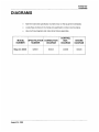
DIAGRAMS
ADDENDUM
WARRANTY
Page 2
February 21, 2000 Revised
430429-427
INTRODUCTION
INTRODUCTION
How To Use This Manual
This Owners Manual usually applies to just the
underlined specification or part numbers listed on
the cover. If none are underlined, they are all cov-
ered by this manual.
Throughout this manual, the words WARNING,
CAUTION, and NOTE may appear. Pay particular
attention to the information provided under these
headings. These special annotations are easily rec-
ognized as follows:
WARNING gives information re-
garding possible personal in-
jury. Warnings will be enclosed
in a box such as this.
CAUTION refers to possible equipment
damage. Cautions will be shown in bold
type.
NOTE offers helpful information concern-
ing certain operating procedures. Notes
will be shown in italics.
Equipment Identification
The unit's identification number (specification or
part number), model, and serial number usually
appear on a nameplate attached to the control
panel. In some cases, the nameplate may be at-
tached to the rear panel. Equipment which does not
have a control panel such as gun and cable assem-
blies are identified only by the specification or part
number printed on the shipping container. Record
these numbers for future reference.
Receipt Of Equipment
When you receive the equipment, check it against
the invoice to make sure it is complete and inspect
the equipment for possible damage due to shipping.
lfthere is any damage, notify the carrier immediately
to file a claim. Furnish complete information con-
cerning damage claims or shipping errors to
Thermal Arc, Order Department, 2200 Corporate
Drive, Troy, Ohio 45373-1085. Include all equipment
identification numbers as described above along
with a full description of the parts in error.
Move the equipment to the installation site before
uncrating the unit. A lifting eye extends through the
top of the cabinet on most equipment to facilitate
handling with a hoist or crane. Use care to avoid
damaging the equipment when using bars, ham-
mers, etc., to uncrate the unit.
WARNING: Falling machine due
to lifting eye failure may cause
death or serious injury.
e Lifting device may fail when overloaded.
This lifting device is designed to lift the
power source ONLY. If the machine is
equipped with a trailer or accessories over
100 pounds, DO NOT LIFT by lifting eyes.
e Avoid sudden jerks, drops, or swinging.
e Check lifting device components visually
for looseness and signs of metal fatigue.
e Before changing any hardware, check
grade and size of bolts, and replace with
bolts of equal or higher size and grade.
Additional copies of this manual may be purchased
by contacting Thermal Arc at the address given
above. Include the Owner's Manual number and
equipment identification numbers.
August 24, 1998
1-1
430429-427
INTRODUCTION
This page intentionally left blank.
1-2 August 24, 1998
ARC WELDING SAFETY INSTRUCTIONS AND WARNINGS
Instruction 830001
ARC WELDING SAFETY INSTRUCTIONS AND WARNINGS
NET
PROTECT YOURSELF AND OTHERS FROM POSSIBLE SERIOUS INJURY OR DEATH. KEEP CHILDREN AWAY. PACEMAKER
ARC WELDING can be hazardous.
WEARERS KEEP AWAY UNTIL CONSULTING YOUR DOCTOR. DO NOT LOSE THESE INSTRUCTIONS. READ OPERATING/INSTRUC-
TION MANUAL BEFORE INSTALLING, OPERATING OR SERVICING THIS EQUIPMENT.
Welding products and welding processes can cause serious injury or death, or damage to other equipment or property, if the operator does
not strictiy observe all safety rules and take precautionary actions.
Safe practices have developed from past experience in the use of welding and cutting. These practices must be learned through study and
training before using this equipment. Anyone not having extensive training in welding and cutting practices should not attempt to weld.
Certain of the practices apply to equipment connected to power lines; other practices apply to engine driven equipment.
Safe practices are outlined in the American National Standard Z49.1 entitled: SAFETY IN WELDING AND CUTTING. This publication and
other guides to what you should learn before operating this equipment are listed at the end of these safety precautions.
HAVE ALL INSTALLATION, OPERATION, MAINTENANCE, AND REPAIR WORK PERFORMED ONLY BY QUALIFIED PEOPLE. .
A
—
ELECTRIC SHOCK can Kill.
Touching live electrical parts can cause fatal shocks
or severe burns. The electrode and work circuit is
electrically live whenever the output is on. The input
power circuit and machine internal circuits are also
live when power is on. in semiautomatic or auto-
matic wire welding, the wire, wire reel, drive roll
housing, and all metal parts touching the welding
wire are electrically live. incorrectly installed or im-
properly grounded equipment is a hazard.
1. Do not touch live electrical parts.
2. Wear dry, hole-free insulating gloves and body protection.
3. Insulate yourself from work and ground using dry insulating
mats or covers.
4. Disconnect input power or stop engine before installing or
servicing this equipment. Lock input power disconnect switch
open, or remove line fuses so power cannot be turned on
accidentally.
5. Properly install and ground this equipment according to its
Owners Manual and national, state, and local codes.
6.
7.
12.
13.
14.
15.
Turn off ali equipment when not in use. Disconnect power to
equipment if it will be left unattended or out of service.
Use fully insulated electrode holders. Never dip holder in water
to cool it or lay it down on the ground or the work surface. Do
not touch holders connected to two weiding machines at the
same time or touch other people with the holder or electrode.
. Do not use worn, damaged, undersized, or poorly spliced ca-
bles.
. Do not wrap cables around your body.
10.
11.
Ground the workpiece to a good electrical (earth) ground.
Do not touch electrode while in contact with the work (ground)
circuit.
Use only weli-maintained equipment. Repair or replace dam-
aged parts at once.
In confined spaces or damp locations, do not use a welder with
AC output unless it is equipped with a voltage reducer. Use
equipment with DC output.
Wear a safety harness to prevent falling if working above floor
level.
Keep all panels and covers securely in place.
hearing.
ARC RAYS can burn eyes and skin;
NOISE can damage hearing.
Arc rays from the weiding process produce intense
heat and strong ultraviolet rays that can burn eyes
and skin. Noise from some processes can damage
4.
5.
. Wear a welding helmet fitted with a proper shade of filter (see
ANSI Z49.1 listed in Safety Standards) to protect your face and
eyes when welding or watching.
. Wear approved safety glasses. Side shields recommended.
. Use protective screens or barriers to protect others from flash
and glare; warn others not to watch the arc.
Wear protective clothing made from durable, flame-resistant
material (wool and leather) and foot protection.
Use approved ear plugs or ear muffs if noise level is high.
Eye protection filter shade selector for welding
or cutting (goggles or helmet), from AWS A6.2-73.
Electrode Size Filter Electrode Size Filter
Welding or Cutting Metal Thickness Shade Welding or Cutting Metal Thickness Shade
Operation or Welding Current No. Operation or Welding Current No.
Torch soldering — 2 Gas metal-arc welding (MIG)
Torch brazing — 3or4 Non-ferrous base metal All 11
Oxygen cutting Ferrous base metal All 12
Light Under 1 in., 25 mm 3or4| Gastungsten arc welding (TIG) All 12
Medium 1 to 6 in, 25-150 mm 40or5 | Atomic hydrogen welding All 12
Heavy Over 6 in., 150 mm 5or6 | Carbon arc welding All 12
Gas welding Plasma arc welding All 12
Light Under 1/8 in., 3 mm 40or5! Carbon arc air gouging
Medium 1/8 to 1/2 in., 3-12mm | 5o0r6 Light 12
Heavy Over 1/2 in., 12 mm 60r8 Heavy 14
Shielded metal-arc welding Under 5/32 in., 4 mm 10 Plasma arc cutting
(stick) electrodes 5/32 to 1/4 in, 4 to 6.4 mm 12 Light Under 300 Amp 9
Over 1/4 in, 6.4 mm 14 Medium 300 to 400 Amp 12
Heavy Over 400 Amp 14
May 8, 1996 2-1
ARC WELDING SAFETY INSTRUCTIONS AND WARNINGS
Instruction 830001
FUMES AND GASES can be hazardous
to your health.
Welding produces fumes and gases. Breathing
these fumes and gases can be hazardous to your
health.
1.
2.
3.
Keep your head out of the fumes. Do not breath the fumes.
if inside, ventilate the area and/or use exhaust at the arc to
remove welding fumes and gases.
If ventilation is poor, use an approved air-supplied respirator.
. Read the Material Safety Data Sheets (MSDSs) and the manu-
facturer's instruction for metals, consumables, coatings, and
cleaners.
. Work in a confined space only if it is well ventilated, or while
wearing an air-supplied respirator. Shielding gases used for
welding can displace air causing injury or death. Be sure the
breathing air is safe.
. Do not weld in locations near degreasing, cleaning, or spraying
operations. The heat and rays of the arc can react with vapors
to form highly toxic and irritating gases.
. Do not weld on coated metals, such as galvanized, lead, or
cadmium plated steel, uniess the coating is removed from the
weld area, the area is well ventilated, and if necessary, while
wearing an air-supplied respirator. The coatings and any metals
containing these elements can give off toxic fumes if weided.
A
WELDING can cause fire or explosion.
Sparks and spatter fly off from the welding arc. The
flying sparks and hot metal, weld spatter, hot work-
piece, and hot equipment can cause fires and burns.
Accidental contact of electrode or welding wire to
metal objects can cause sparks, overheating, or fire.
~~
AN
. Protect yourself and others from flying sparks and hot metal.
. Do not weld where flying sparks can strike flammable material.
. Remove all flammables within 35 ft (10.7 m) of the welding arc.
If this is not possible, tightly cover them with approved covers.
5. Watch for fire, and keep a fire extinguisher nearby.
6. Be aware that welding on a ceiling, floor, bulkhead, or partition
10.
can cause fire on the hidden side.
. Do not weld on closed containers such as tanks or drums.
. Connect work cable to the work as close to the welding area as
practical to prevent welding current from traveling long, possibly
unknown paths and causing electric shock and fire hazards.
. Do not use welder to thaw frozen pipes.
Remove stick electrode from holder or cut off welding wire at
contact tip when not in use.
Engines produce harmful exhaust gases.
4. Be alert that welding sparks and hot materials from welding can 11. Wear oil-free protective garments such as leather gloves, heavy
easily go through small cracks and openings to adjacent areas. shirt, cuffless trousers, high shoes, and a cap.
в FLYING SPARKS AND HOT METAL can
cause Injury. 1. Wear approved face shield or safety goggles. Side shields
CA Chipping and grinding cause flying metal. As welds recommended.
~~ cool, they can throw off slag. 2. Wear proper body protection to protect skin.
CYLINDERS can explode if damaged. 3. Keep cylinders away from any welding or other electrical cir-
| cuits.
Е | ; ; 4. Never allow a welding electrode to touch any cylinder.
Shielding gas cylinders contain gasunderhighpres- 5 Use only correct shielding gas cylinders, regulators, hoses, and
sure. If damaged, a cylinder can explode. Since gas fittings designed for the specific application; maintain them and
cylinders are normally part of the welding process, associated parts in good condition.
be sure to treat them carefully. ;
6. Turn face away from valve outlet when opening cylinder valve.
7. Keep protective cap in place over valve except when cylinder is
1. Protect compressed gas cylinders from excessive heat, me- in use or connected for use.
chanical shocks, and arcs. 8. Read and follow instructions on compressed gas cylinders,
2. Install and secure cylinders in an upright position by chaining associated equipment, and CGA publication P-1 listed in Safety
them to a stationary support or equipment cylinder rack to Standards.
prevent falling or tipping.
ENGINES can be hazardous.
ENGINE EXHAUST GASES can kill. 1. Use equipment outside in open, well-ventilated areas.
2. if used in a closed area, vent engine exhaust outside and away
from any building air intakes.
2-2
May 8, 1996
ARC WELDING SAFETY INSTRUCTIONS AND WARNINGS
Instruction 830001
ENGINE FUEL can cause fire or
explosion.
Engine fuel is highly flammable.
1. Stop engine before checking or adding fuel.
2. Do not add fuel while smoking or if unit is near any sparks or open
flames,
3. Allow engine to cool before fueling. If possible, check and add
fuel to cold engine before beginning job.
4. Do not overfill tank — allow room for fuel to expand.
5. Do not spill fuel. If fuel is spilled, clean up before starting engine.
MOVING PARTS can cause injury.
Moving parts, such as fans, rotors, and belts can cut
fingers and hands and catch loose clothing.
Ve
1. Keep all doors, panels, covers, and guards closed and securely
in place.
2. Stop engine before installing or connecting unit.
3. Have only qualified people remove guards or covers for mainte-
nance and troubleshooting as necessary.
4. To prevent accidental starting during servicing, disconnect nega-
tive (-) battery cable from battery.
5. Keep hands, hair, loose clothing, and tools away from moving
parts.
6. Reinstall panels or guards and close doors when servicing is
finished and before starting engine.
COOLANT can burn face, eyes, and
skin.
The coolant in the radiator can be very hot and under
pressure.
SPARKS can cause BATTERY GASES 1. Always wear a face shield when working on a battery.
TO EXPLODE; BATTERY ACID can 2. Stop engine before disconnecting or connecting battery cables.
burn eyes and skin. 3. Do not allow tools to cause sparks when working on a battery.
Batteries contain acid and generate explosive gases. 4. Do not use welder to charge batteries or jump start vehicles.
5. Observe correct polarity (+ and —) on batteries.
STEAM AND PRESSURIZED HOT 1. Do not remove radiator cap when engine is hot. Allow engine to
cool.
2. Wear gloves and put a rag over cap area when removing cap.
3. Allow pressure to escape before completely removing cap.
WARNING: This product, when used for welding or cutting, produces fumes or gases which contain chemicals known to the State
of California to cause birth defects and, in some cases, cancer.
(California Health & Safety Code Sec. 25249.5 et seq.)
NOTE: Considerations About Welding And The Effects Of Low Frequency Electric And Magnetic Fields
The following is a quotation from the General Conclusions Section of the U.S. Congress, Office of Technology Assessment, Biological Effects
of Power Frequency Electric & Magnetic Fields — Background Paper, OTA-BP-E-63 (Washington, DC: U.S. Government Printing Office, May
1989): “... there is now a very large volume of scientific findings based on experiments at the cellular level and from studies with animals and
people which clearly establish that low frequency magnetic fields can interact with, and produce changes in, biological systems. While most of
this work is of very high quality, the results are complex. Current scientific understanding does not yet allow us to interpret the evidence in a
single coherent framework. Even more frustrating, it does not yet allow us to draw definite conclusions about questions of possible risk or to
offer clear science-based advice on strategies to minimize or avoid potential risks.”
To reduce magnetic fields in the workplace, use the following procedures:
1. Keep cables close together by twisting or taping them.
2. Arrange cables to one side and away from the operator.
About Pacemakers:
3. Do not coil or drape cables around the body.
4. Keep welding power source and cables as far away from body as
practical.
The above procedures are among those also normally recommended for pacemaker wearers. Consult your doctor for complete information.
PRINCIPAL SAFETY STANDARDS
Safety in Welding and Cutting, ANSI Standard Z49.1, from American
Welding Society, 550 NW. LeJeune Rd., Miami, FL 33126.
Safety and Health Standards, OSHA 28 CFR 1910, from Superinten-
dent of Documents, U.S. Government Printing Office, Washington,
D.C. 20402.
Recommended Safe Practices for the Preparation for Welding and
Cutting of Containers That Have Held Hazardous Substances, Ameri-
can Welding Society Standard AWS F4.1, from American Welding
Society, 550 N.W. LeJeune Rd., Miami, FL 33126.
National Electrical Code, NFPA Standard 70, from National Fire
Protection Association, Batterymarch Park, Quincy, MA 02269.
Safe Handling of Compressed Gases in Cylinders, CGA Pamphlet
P-1, from Compressed Gas Association, 1235 Jefferson Davis High-
way, Suite 501, Arlington, VA 22202.
Code for Safety in Welding and Cutting, CSA Standard W117.2, from
Canadian Standards Association, Standards Sales, 178 Rexdale
Boulevard, Rexdale, Ontario, Canada MSW 1R3.
Safe Practices for Occupation and Educational Eve and Face Pro-
tection, ANSI Standard Z87.1, from American National Standards
Institute, 1430 Broadway, New York, NY 10018.
Cutting and Welding Processes, NFPA Standard 51B, from National
Fire Protection Association, Batterymarch Park, Quincy, MÁ 02269.
September 22, 1999 Revised
2-3
ARC WELDING SAFETY INSTRUCTIONS AND WARNINGS
Instruction 830001
This page intentionally left blank.
2-4 May 8, 1996
PRECAUTIONS DE SECURITE EN SOUDAGE A LARC
Instruction 830002
PRECAUTIONS DE SECURITE EN SOUDAGE A L ARC
MI SE EN GARDE a LE SOUDAGE A L'ARC EST DANGEREUX
PROTEGEZ-VOUS, AINSI QUE LES AUTRES, CONTRE LES BLESSURES GRAVES POSSIBLES OU LA MORT. NE LAISSEZ PAS LES
ENFANTS S’APPROCHER, NI LES PORTEURS DE STIMULATEUR CARDIAQUE (A MOINS QU'ILS N'AIENT CONSULTE UN
MEDECIN). CONSERVEZ CES INSTRUCTIONS. LISEZ LE MANUEL D'OPERATION OU LES INSTRUCTIONS AVANT D'INSTALLER,
UTILISER OU ENTRETENIR CET EQUIPEMENT.
Les produits et procédés de soudage peuvent sauser des blessures graves ou la mort, de même que des dommages au reste du matériel
et à la propriété, si l'utilisateur n'adhère pas strictement à toutes les règles de sécurité et ne prend pas tes précautions nécessaires.
En soudage et coupage, des pratiques sécuritaires se sont développées suite à l'expérience passée. Ces pratiques doivent être apprises
par étude ou entraînement avant d'utiliser l'equipement. Toute personne n'ayant pas suivi un entraînement intensif en soudage et coupage
ne devrait pas tenter de souder. Certaines pratiques concernent les équipements raccordés aux lignes d'alimentation alors que d’autres
s'adressent aux groupes électrogènes.
La norme Z49.1 de l'American National Standard, intitulée “SAFETY IN WELDING AND CUTTING” présente les pratiques sécuritaires à
suivre. Ce document ainsi que d'autres guides que vous devriez connaître avant d'utiliser cet équipement sont présentés à la fin de ces
instructions de sécurité.
SEULES DES PERSONNES QUALIFIEES DOIVENT FAIRE DES TRAVAUX D’INSTALLATION, DE REPARATION, D'ENTRETIEN ET
D'ESSAI.
L’'ELECTROCUTION PEUT ETRE 6. Arrêtez tout équipement après usage. Coupez l'alimentation de
MORTELLE. l'équipement s’il est hors d'usage ou inutilisé.
7 Une décharge électrique peut tuer ou brûler grave- 7. N'utilisez que des porte-électrodes bien isolés. Ne jamais plon-
_ ment. L'électrode et le circuit de soudage sont sous ger les porte-électrodes dans l’eau pour les refroidir. Ne jamais
les laisser traîner par terre ou sur les pièces à souder. Ne touchez
pas aux porte-électrodes raccordés à deux sources de courant
en même temps. Ne jamais toucher quelqu'un d'autre avec
I'électrode ou le porte-électrode.
8. N'utilisez pas de câbles électriques usés, endommagés, mal
épissés ou de section trop petite.
tension dès la mise en circuit. Le circuit d'alimenta-
tion et les circuits internes de l'équipement sont
aussi sous tension dès la mise en marche. En
soudage automatique ou semi-automatique avec
fil, ce dernier, le rouleau ou la bobine de fil, le
logement des galets d'entrainement et toutes les
pièces métalliques en contact avec le fil de soudage 9. N'enroulez pas de câbles électriques autour de votre corps.
| _ sont sous tension. Un equipement inadequatement 10. N’utilisez qu’une bonne prise de masse pour la mise à la terre
installé ou inadéguatement mis a la terre est dangereux. de la pièce à souder. |
1. Ne touchez pas à des pièces sous tension. 11. Ne touchez pas à l’électrode lorsqu’en contact avec le circuit de
soudage (terre).
12. N'utilisez que des équipements en bon état. Réparez ou rem-
placez aussitôt les pièces endommagées.
13. Dans des espaces confinés ou mouillés, n'utilisez pas de source
le moteur avant de l'installer ou d'en faire l'entretien. Bloquez le de courant alternatif, à moins qu'il soit muni d'un réducteur de
commutateur en circuit ouvert ou enievez les fusibles de l'ali- tension. Utilisez plutôt une source de courant continu.
mentation afin d'éviter une mise en marche accidentelle. 14. Portez un harnais de sécurité si vous travaillez en hauteur.
5. Veuillez à installer cet équipement et à le mettre à ia terre selon 15. Fermez solidement tous les panneaux et les capots.
le manuel d'utilisation et les codes nationaux, provinciaux et
locaux applicables.
2. Portez des gants et des vêtements isolants, secs et non troués.
3. Isolez-vous de la pièce à souder et de ia mise à la terre au moyen
de tapis isolants ou autres.
4. Déconnectez la prise d’alimentation de l'équipement ou arrêtez
pour vous protéger le visage et les yeux lorsque vous soudez ou
que vous observez l’exécution d'une soudure.
LE RAYONNEMENT DE L'ARC PEUT A
BRULER LES YEUX ET LA PE AU: LE 2. cortez des uneties de sécurité approuvées. Des écrans latéraux
BRUIT PEUT ENDOMMAGER L'OUIE. 3
. Entourez l'aire de soudage de rideaux ou de cloisons pour
l’arc de soudage produit une chaleur et des protéger les autres des coups d'arc ou de l'éblouissement;
rayons ultraviolets intenses, susceptibles de avertissez les observateurs de ne pas regarder l'arc.
brûler les yeux et la peau. Le bruit causé par 4. Portez des vêtements en matériaux ignifuges et durables (laine
certains procédés peut endommager l'oule. et cuir) et des chaussures de sécurité.
5. Portez un casque antibruit ou des bouchons d'oreille approuvés
1. Portez une casque de soudeur avec filtre oculaire de nuance ner
lorsque le niveau de bruit est élevé.
appropriée (consultez la norme ANSI Z49 indiquée ci-après)
8-V-96 2-1
PRECAUTIONS DE SECURITE EN SOUDAGE À L’ARC
Instruction 830002
SELECTION DES NUANCES DE FILTRES OCULAIRES POUR LA PROTECTION DES YEUX EN COUPAGE ET SOUDAGE
( selon AWS A 8.2-73 )
Opération Dimension d'électrode ou Nuance de
de Epaisseur de métal ou de filtre
Coupage ou soudage Intensité de courant oculaire
brasage tendre au chalumeau toutes conditions 2
Brasage fort au chalumeau toutes conditions 3ou4
Oxycoupage
mince moins de 1 po. (25 mm) 2 ou 3
moyen de 1 à 6 po. (25 à 150 mm) 4 ou 5
épais plus de 6 po. (150 mm) 5ou6
Soudage aux gaz
mince moins de 1/8 po. (3 mm) 4 ou 5
moyen de 1/8 à 1/2 po. (3 à 12 mm) 50u6
épais plus de 1/2 po. (12 mm) 6 ou 8
Soudage à l'arc avec moins de 5/32 po. (4 mm) 10
electrode enrobées (SMAW) de 5/32 a 1/4 po. (4 46.4 mm) 12
plus de 1/4 po. (6.4 mm) 14
Soudage à l'arc sous gaz
avec fil plein (GMAW)
métaux non-ferreux toutes conditions 11
métaux ferreux toutes conditions 12
Soudage à l'arc sous gaz
avec électrode de tungstène (GTAW) toutes conditions 12
Soudage à l'hydrogène
atomique (AHW) toutes conditions 12
Soudage à l’arc avec
electrode de carbone (CAW) toutes conditions 12
Soudage á l'arc Plasma (PAW) toutes dimensions 12
Gougeage Air-Arc avec
électrode de carbone
mince 12
épais 14
Coupage a Parc Piasma (PAC)
mince moins de 300 ampéres 9
moyen de 300 à 400 ampères 12
épais plus de 400 ampères 14
LES VAPEURS ET LES FUMEES SONT
DANGEREUSES POUR LA SANTE.
Le soudage dégage des vapeurs et des fumées
dangereuses à respirer.
. Eloignez la tête des fumées pour éviter de les respirer.
. Al'intérieur, assurez-vous que l’aire de soudage est bien ven-
tilée ou que les fumées et les vapeurs sont aspirées à l'arc.
. Si la ventilation est inadequate, portez un respirateur à adduc-
tion d'air approuvé.
. Lisez les fiches signalétiques et les consignes du fabricant
relatives aux métaux, aux produits consummables, aux revéte-
ments et aux produits nettoyants.
5. Ne travaillez dans un espace confiné que s'il est bien ventilé;
sinon, portez un respirateur à adduction d'air. Les gaz protec-
teurs de soudage peuvent déplacer l’oxygène de l'air et ainsi
causer des malaises ou la mort. Assurez-vous que l'air est
propre à la respiration.
. Ne soudez pas à proximité d'opérations de dégraissage, de
nettoyage ou de puivérisation. La chaleur et les rayons de l'arc
peuvent réagir avec des vapeurs et former des gaz hautement
toxiques et irritants.
. Ne soudez des tôles galvanisées ou plaquées au plomb ou au
cadmium que si les zones à souder ont été grattées à fond, que
si l'espace est bien ventilé; si nécessaire portez un respirateur
à adduction d'air. Car ces revêtements et tout métal qui con-
tient ces éléments peuvent dégager des fumées toxiques au
moment du soudage.
8-V-96
PRECAUTIONS DE SECURITE EN SOUDAGE A L’ARC
Instruction 830002
LE SOUDAGE PEUT CAUSER UN IN-
CENDIE OÙ UNE EXPLOSION
L’arc produit des étincellies et des projections. Les
particules volantes, le métal chaud, les projections
de soudure et l'équipement surchauffé peuvent
causer un incendie et des brûlures. Le contact
accidentel de l'électrode ou du fil-électrode avec un
objet métallique peut provoquer des étincelles, un échauffement
ou un incendie.
1. Protégez-vous, ainsi que les autres, contre les étincelles et du
métal chaud.
2. Ne soudez pas dans un endroit où des particules volantes ou
des projections peuvent atteindre des matériaux inflammabies.
3. Enlevez toutes matières inflammables dans un rayon de 10, 7
mètres autour de l’arc, ou couvrez-les soigneusement avec des
bâches approuvées.
14.
. Méfiez-vous des projections brulantes de soudage suscep-
tibles de pénétrer dans des aires adjacentes par de petites
ouvertures ou fissures.
. Méfiez-vous des incendies et gardez un extincteur à portée de
la main.
. N'oubliez pas qu'une soudure réalisée sur un plafond, un
plancher, une cloison ou une paroi peut enflammer l'autre côté.
. Ne soudez pas un récipient fermé, tel un réservoir ou un baril.
. Connectez le câble de soudage le plus près possible de la zone
de soudage pour empêcher ie courant de suivre un long par-
cours inconnu, et prévenir ainsi les risques d'électrocution et
d'incendie.
. Ne dégelez pas tes tuyaux avec un source de courant.
10.
Otez l’électrode du porte-électrode ou coupez ie fil au tube-con-
tact lorsqu’inutilisé après le soudage.
Portez des vêtements protecteurs non huileux, teis dés gants
en cuir, une chemise épaisse, un pantalon revers, des bottines
de sécurité et un casque.
LES ETINCELLES ET LES PROJEC-
TIONS BRULANTES PEUVENT
CAUSER DES BLESSURES.
Le piquage et le meulage produisent des particules métailiques
volantes. En refroidissant, la soudure peut projeter du éciats de
laitier.
4.
2.
Portez un écran facial ou des lunettes protectrices approuvées.
Des écrans latéraux sont recommandés.
Portez des vêternents appropriés pour protéger la peau.
LES BOUTEILLES ENDOMMAGEES
PEUVENT EXPLOSER
Les bouteilles contiennent des gaz protecteurs
sous haute pression. Des bouteilles endommagées
peuvent exploser. Comme les bouteilles font nor-
malement partie du procédé de soudage, traitez-
les avec soin.
1. Protégez les bouteilles de gaz comprimé contre les sources de
chaleur intense, les chocs et les arcs de soudage.
2. Enchainez verticalement les bouteilles à un support ou à un
cadre fixe pour les empêcher de tomber ou d'être renversées.
3. Eloignez les bouteilles de tout circuit électrique ou de tout
soudage.
. Empêchez tout contact entre une bouteille et une électrode de
soudage.
. N'utilisez que des bouteilles de gaz protecteur, des détendeurs,
des boyauxs et des raccords conçus pour chaque application
spécifique; ces équipements et les pièces connexes doivent
être maintenus en bon état.
. Ne placez pas le visage face à l'ouverture du robinet de la
bouteille lors de son ouverture.
. Laissez en place le chapeau de bouteille sauf si en utilisation
ou lorsque raccordé pour utilisation.
. Lisez et respectez les consignes relatives aux bouteilles de gaz
comprimé et aux équipements connexes, ainsi que la publica-
tion P-1 de la CGA, identifiée dans la liste de documents
ci-dessous.
LES GAZ D'ECHAPPEMENT DES
MOTEURS PEUVENT ETRE MORTELS.
Les moteurs produisent des gaz d'échappement
nocifs.
LES MOTEURS PEUVENT ETRE DANGEREUX
. Utilisez l'équipement à l'extérieur dans des aires ouvertes et
bien ventilées.
. Si vous utilisez ces équipements dans un endroit confiné, les
fumées d'échappement doivent être envoyées à l'extérieur, loin
des prises d'air du bâtiment.
LE CARBURANT PEUR CAUSER UN IN-
CENDIE OU UNE EXPLOSION.
|e carburant est hautement inflammable.
1. Arrétez le moteur avant de vérifier le niveau de
carburant ou de faire le piein.
. Ne faites pas le plein en fumant ou proche d'une source
d'étincelles ou d'une fiamme nue.
. Si c'est possible, laissez le moteur refroidir avant de faire le
plein de carburant ou d’en vérifier le niveau au début du
soudage.
. Ne faites pas le plein de carburant à ras bord: prévoyez de
l’espace pour son expansion.
. Faites attention de ne pas renverser de carburant. Nettoyez tout
carburant renversé avant de faire démarrer ie moteur.
8-V-96
PRECAUTIONS DE SECURITE EN SOUDAGE A L’ARC
Instruction 830002
~ DES PIECES EN MOUVEMENT PEU-
ve | VENT CAUSER DES BLESSURES.
+ .. .
Des pièces en mouvement, tels des ventilateurs, des
rotors et des courroies peuvent couper doigts et
mains, ou accrocher des vétements amples.
1. Assurez-vous que les portes, les panneaux, les capots et les
protecteurs soient bien fermés.
2. Avant d'installer ou de connecter un système, arrêtez le moteur.
3. Seules des personnes qualifiées doivent démonter des protec-
teurs ou des capots pour faire l'entretien ou le dépannage
nécessaire.
4. Pour empêcher un démarrage accidente! pendant l'entretien,
débranchez le câble d'accumulateur à la borne négative.
5. N'approchez pas les mains ou les cheveux de pièces en mou-
vement; elles peuvent aussi accrocher des vêtements amples
et des outils.
6. Réinstaliez les capots ou les protecteurs et fermez les portes
après des travaux d'entretien et avant de faire démarrer le
moteur.
DES ETINCELLES PEUVENT FAIRE EX-
PLOSER UN ACCUMULATEUR;
L’ELECTROLYTE D'UN ACCUMU-
LATEUR PEUT BRULER LA PEAU ET
LES YEUX.
Les accumulateurs contiennent de l’électrolyte
acide et dégagent des vapeurs explosives.
1. Portez toujours un écran facial en travaillant sur un accumu-
lateur.
2. Arrêtez le moteur avant de connecter ou de déconnecter des
câbles d'accumulateur.
3. N'utilisez que des outils anti-étincelles pour travailler sur un
accumulateur.
4. N’utilisez pas une source de courant de soudage pour charger
un accumulateur ou survolter momentanément un véhicule.
5. Utilisez la polarité correcte (+ et —) de l'accumulateur.
LA VAPEUR ET LE LIQUIDE DE RE-
FROIDISSEMENT BRULANT SOUS
PRESSION PEUVENT BRULER LA
PEAU ET LES YEUX.
Le liquide de refroidissement d'un radiateur peut
être brûlant et sous pression.
1. N'ôtez pas le bouchon de radiateur tant que le moteur n'est pas
refroidi.
2. Mettez des gants et posez un torchon sur le bouchon pour l'ôter.
3. Laissez la pression s'échapper avant d'ôter complètement le
bouchon.
PRINCIPALES NORMES DE SECURITE
Safety in Welding and Cutting, norme ANSI Z49.1, American Weld-
ing Society, 550 N.W. LeJeune Rd., Miami, FL 33128.
Safety and Health Standards, OSHA 28 CFR 1910, Superintendent
of Documents, U.S. Government Printing Office, Washington, D.C.
20402.
Recommended Safe Practices for the Preparation for Welding and
Cutting of Containers That Have Held Hazardous Substances,
norme AWS F4.1, American Welding Society, 550 NW. LeJeune Rd.,
Miami, FL 33128.
National Electrical Code, norme 70 NFPA, National Fire Protection
Association, Batterymarch Park, Quincy, MÁ 02269.
Safe Handling of Compressed Gases in Cylinders, document P-1,
Compressed Gas Association, 1235 Jefferson Davis Highway, Suite
501, Arlington, VA 22202.
Code for Safety in Welding and Cutting, norme CSA W117.2 Asso-
ciation canadienne de normalisation, Standards Sales, 276 Rexdale
Boulevard, Rexdale, Ontario, Canada M9W 1R3.
Safe Practices for Occupation and Educational Eye and Face Pro-
tection, norme ANSI Z87.1, American National Standards Institute,
1430 Broadway, New York, NY 10018.
Cutting and Welding Processes, norme 518 NFPA, National Fire
Protection Association, Batterymarch Park, Quincy, MA 02268.
2-4
8-V-96
430429-427
DESCRIPTION OF EQUIPMENT
DESCRIPTION OF EQUIPMENT
Generator
The Mega-Arc® diesel engine-driven arc welding
machine is a self-contained unit, mounted on a
welded steel frame. The unit is covered by a sheet
metal canopy, bolted directly to the frame. The
control panel is at the back (generator) end of the
unit.
The generator is an asynchronous brushless self-
excited design. The rotor assembly is supported on
a heavy duty shaft by a single bearing at the rear and
a flexible disc coupling at the engine flywheel.
The generator is a self-excited design utilizing AC
capacitors permanently connected to an excitation
winding on the stator.
The welding circuit 3-phase, wye connected, rec-
tified to DC power by the output rectifier, and stabi-
lized by the stability reactor. The auxiliary power
current provides 115-volt and 230-volt AC power to
the receptacles on the Control Panel for operation
of small tools, lights, etc. See Tabulated Data for
‘rated auxiliary power of your unit.
Engine
The engine used in this unit is a Perkins Industrial
3-162 diesel engine. It is directly coupled to the
welding generator shaft by a flexible coupling.
Identification
The welding generator unit has an identification
plate attached to the control panel on the left-hand
side. The unit is identified as to SPEC number, by
the dash (—) number which follows it.
The engine identification number is stamped on
right-hand side ofthe cylinder block. When ordering
spare parts, or communicating about this machine,
be sure to specify the engine serial number, engine
type, unit specification and serial numbers. Left-and
right-hand sides of the unit are determined when
facing the control panel. See Supplementary Mate-
rials for address for communicating or ordering
engine parts.
Tabulated Data
Generator:
Output, Auxiliary Power. . 3kVA, 115/230V AC
Output, Welding Generator ......... 12 KW
Amperes, rated ................ 300 Amps
Voltage, rated ................... 40 Volts
Voltage, open-circuit ....... (max.) 75 Volts
Duty Cycle, rated .................. 100%
Current Range —
Ce Low Range 15to 200 À
LL LL 1111200 High Range 30 to 400 A
Operating Speed ......... See Engine Data
Engine:
Make and model —
SE Detroit Diesel/Perkins 3-152
TYPE Industrial diesel
Displacement ....... 152 cu. in. (2.50 liters)
Brake horsepower .... 38 BHP @ 1800 RPM
Oil sump capacity. . . . .. 7-1/2 quarts (7 liters)
Cooling system capacity —
aaa eee 912 quarts (Q liters)
Fuel tank capacity —
ana 17 gallons (U.S.) (64.4 liters)
Weight (dry) .......... 463 pounds (210 kg)
Normal operating RPM. ......... 1800 RPM
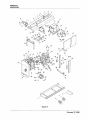
Dimensions and Weight: (See Figure 4-1)
Width (doors closed) ... 28 inches (711 mm)
Width (doors open). ... 77 inches (1956 mm)
Length........... 61-1/2 inches (1562 mm)
Height (top of canopy) —
Ce 41 inches (1041 mm)
Height (over eye in top) —
Ce 46 inches (1168 mm)
Weight (shipping) —
ee approx. 1700 pounds (765 kg)
August 24, 1998
3-1
430429-427
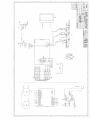
DESCRIPTION OF EQUIPMENT
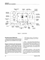
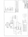
Range Selector
Switch
Current Arc Force 15 Am
Control Ampere Control Circuit
Breakers
Voltmeter
(Optional)
Ammeter
(Optional) —
115 Volt
Receptacle
230 Volt
— —— Receptacle
Control Box___— Current
Door ©: Control
E Switch
Fuel 8
Gauge © $
Contactor 8
Control — 8 Ba Remote
Switeh ©) \ A A Receptacle
Throttle Ignition Thermostart Hour
Switch Pushbutton Alternator Water eter
Oil Pressure 8 Temp.
Light Gauge A—467
Figure 3-1 Control Panel
Supplementary Materials
A copy ofthe Perkins Handbook for Diesel Engines
is included with each welding generator unit. Addi-
tional copies may be obtained from the manufac-
turer.
Engine Controls and Instruments
Ignition Switch — The diesel engine starting motor
is actuated by this switch, located in the lower
left-hand corner of the control panel. Do NOT crank
the engine for more than 30 seconds at a time, as
this may cause the starting motor to overheat. Allow
motor to cool before attempting to start the engine
again. Place switch in START position to start, and
return to RUN position after the engine has started.
When engine is shut down, place switch in OFF
position.
NOTE: Switch must be in OFF position to
avoid lighting the Alternator and Oil Pres-
sure light.
Throttle — This control shuts the diesel fuel sup-
ply off, for normal shutdown of the engine. Pull the
control handle OUT all the way for engine to run at
rated RPM (1800). Push the handle / against the
panel! to shut engine down. Turn contro! handle
counterclockwise to loosen, and clockwise to lock
it in position.
Thermostart Pushbutton — Place the starter
switch in RUN position and hold the pushbutton IN
for 15 to 20 seconds, prior to placing the starter
switch in START position. Continue to hold it /N until
engine fires.
3-2
August 24, 1998
430429-427
DESCRIPTION OF EQUIPMENT
CAUTION: Do not hold the pushbutton
IN for any longer period of time than the
20 seconds (above). If engine does not
start first time, place starter switch in
OFF position, then repeat above proce-
dure.
Oil Pressure Light — Glows (red) when oil pressure
drops to 3-5 psi for any reason.
Alternator Light — Glows when engine alternator
circuit is not charging the battery at sufficient level.
Fuel Gauge — Indicates level of fuel in fuel tank.
Hour Meter — Indicates run time on engine.
Water Temp. Gauge — Indicates coolant tempera-
ture.
Generator Controls
Range Selector Switch — This toggle switch is
used to select either the low or high welding range,
as indicated on the Current Control.
Current Control — The welding current control is
located in the center of the control box door panel.
Turning knob clockwise will increase welding cur-
rent, counterclockwise will decrease current.
Voltmeter (Optional) — Indicates open-circuit and
welding arc voltage, when supplied.
Ammeter (Optional) — Indicates welding current
being used to weld, when supplied.
Arc Force Ampere Control — Varies the short-cir-
cuit (welding arc) current and produces an increase
of amperage when arc length is shortened. Turning
this control clockwise increases arc force, counter-
clockwise decreases arc force. See Operation
chapter for details.
Welding Terminals — (See Figure 3-2) — The two
welding terminals are located on the Welding Output
Panel, which is located on the left-hand side of the
unit (facing the control panel). See instructions in
Initial Preparation for Use located in the Installation
chapter.
Auxiliary Power Receptacle — Duplex receptacles
located on the Control Panel (see Figure 3-1) furnish
3-KVA, 115-volt and 230-volt, 60-Hz power.
NOTE: The output voltage will drop below
the rated volts when engine is in the idling
mode. Low voltage may damage electrical
equipment connected to the generator
through this receptacle.
Welding
Terminals
Figure 3-2 Weld Output Panel
August 24, 1998
430429-427
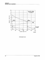
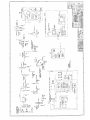
DESCRIPTION OF EQUIPMENT
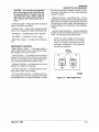
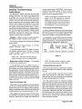
WELDING VOLTS (DC)
100
VOLT-AMP CURVES
90 MODEL MA-4030D
(TYPICAL)
B0-
oS
50 BD.
50-H— LOW — HIGH
MINIMUM MAXIMUM
и —
40- > 1 NEMA
_ + LINE
30 ===
ma — - 7
- =” - = 7
20- =
Ne - UTIL ARC FORCE
10- — = NL SETTINGS
\ N А ~ \ > > 10
0,2 > =~ 0 0 2 5 So
O { ^ > 2 [ >
0 100 200 300 400 500 600
WELDING AMPS (DC
(DC) А-457
Volt-Ampere Curve
3-4
August 24, 1998
430429-427
INSTALLATION
INSTALLATION
General Engine Driven Welder
Installation
The frame of an engine driven welder is intended
to be a base to held the welder components to-
gether. This frame is not intended to be the primary
structure of a trailer or wagon. This welder is in-
tended to be installed on a rigid, flat surface. This
surface must allow the weight of the welder to be
distributed evenly along the length of the welder
frame.
Never install any vibration isolation material (shock
mounts, etc.) beneath the welder frame. This could
defeat the engine/generator shock mounts and
cause abnormal vibration throughout the welder
and produce vibration related problems.
Before choosing an installation location, make
note of where the service items are located on the
welder (oil change/fill, battery, air filter, fuel fill, etc.)
Install the welder for best access to the important
service items. Allow sufficient room for cooling air
intake and exhaust.
if you are unsure about any installation consult the
factory.
Trailer Installation: Do not use the frame assem-
bly of this welder as the frame of a trailer (do not
attach axles or tongues directly to this frame). When
a trailer is required, use only trailers with its own
support frame that has a gross weight rated to carry
the weight of the welder and any other components
mounted on the trailer. Be sure the trailer tires are
for use with trailers. The soft sidewall design used in
radial tires can cause vibration related problems. Be
sure welder frame and trailer frame are electrically
bonded together.
Truck Bed Installation: When installing this
welder on the bed of a truck allow the welder to sit
flat on the bed, or a surface which completely con-
tacts the bottom of the welder frame. Do not modify
the welder frame by cutting or otherwise damaging
it or the warranty may be voided. Bolt the welder
frame directly to the bed to secure it. Do not install
any vibration absorption device (shock mounts, etc)
between the welder and the truck bed. Be sure
welder frame and truck frame are electrically
bonded together.
Ground Installation: The welder will operate per-
fectly fine just sitting on the ground, with or without
the shipping skid. No special precautions are re-
quired.
Location
For best operating characteristics and longest unit
life, take care in selecting an installation site. Avoid
locations exposed to high humidity, dust, high am-
bient temperature, or corrosive fumes. Moisture can
condense on electrical components, causing corro-
sion or shorting of circuits. Dirt on components
helps retain this moisture and also increases wear
on moving parts.
Safety
Refer to additional installation instructions under
the Safety Warnings chapter included in this man-
ual.
Indoor Installation
Adequate air circulation is needed at all times in
order to assure proper operation. Provide at least
24 inches (610 mm) of space at radiator end of unit.
Make sure that ventilation openings are not ob-
structed. Allow ample space to open canopy doors
on sides of the unit (see Tabulated Data in Descrip-
tion of Equipment chapter for dimensions) for serv-
icing, and space at the control panel end of unit for
operation.
If unit is to be operated inside a building, make
certain there is adequate ventilation to carry off
escaping exhaust fumes and to provide an ample
supply of oxygen.
Place unit so that exhaust fumes are carried out of
the building using the shortest exhaust pipe possi-
ble and one with the fewest possible number of
bends. Exhaust back pressure can seriously affect
engine efficiency.
All exhaust connections must be gastight.
Portable Installation
For portable use, the machine may be located
within 12 inches (305 mm) of a truck cab, panel, or
whatever, if it is to be operated in the open air.
The engine of the welding machine must be placed
at the tongue end of the portable mounting for
proper balance. if leads, etc., are to be stored on the
August 24, 1998
4-1
430429-427
INSTALLATION
unit, they must be forward of the axle to maintain
proper balance of loading on the tongue end of the
unit.
NOTE: The unit should be operated in as
near a normal horizontal position as possi-
ble and never at a tilt greater than 10° side-
ways and/or 7° maximum, rear down.
Initial Preparation For Use
1. Open canopy doors on sides of engine.
CAUTION: The canopy doors may fall to
a closed position during operation of the
unit if it is resting on an inclined surface,
or for other reasons. Tie the doors to
each other, to lifting eye or fuel filler cap.
Failure to do so may result in injury to
operating personnel.
2. Inspect unit thoroughly to be sure it is in proper
working order. Check all fuel and wire connections
to be certain they are secure. Tighten any loose
screws, nuts, or bolts. Check closely for any dam-
age which may have occurred in transit.
3. Remove all special tags from the machine, read
carefully and follow any special directions they may
carry. Keep tags with manual for future reference.
4. Make certain that all radiator air passages and
cooling fins are free from foreign matter. Use clean,
dry compressed air to blow dirt and dust out of
cooling passages and control cabinet, 25 psi (172
kPa) maximum pressure.
5. Attach battery cables to poles of battery as
indicated on wiring diagram. The negative (—) pole
should be grounded to the frame of the unit in a
secure manner.
WARNING: Connect proper bat-
tery cable clamp to the positive
(+ ) battery post first, then the
other cable clamp to the nega-
tive (—) post.
CAUTION: A short circuit to rectifier is
created if a battery is installed with po-
larity reversed. Current can flow from
positive terminal of battery through
negative and positive rectifiers and into
heat sink. From heat sink a completed
circuit exists back to negative battery
terminal. Full battery voltage will be im-
pressed on rectifiers, in the alternator.
The resulting high current will damage
rectifiers and/or wiring harness.
6. Fill fuel tank with grade of fuel recommended by
engine manufacturer. (Consult engine instruction
manual.) Be sure fuel is free of WATER and other
foreign matter. Make sure air vent to fuel tank is
open. See Safety Warnings chapter included in this
manual for precautions necessary when filling the
tank.
7. Check to be sure that radiator is full (about 1"
below neck). If not, add enough coolant (560/50 mix
of water and antifreeze) to fill.
8. Pull the dipstick and check the oil level in crank-
case. Ifit is necessary to add oll, fill to dipstick mark
with correct seasonal grade of quality detergent oil.
See engine operator's manual for recommended
viscosity and temperature chart (unit is shipped with
SAE 10W30 oil installed).
9. After engine has been properly prepared for use,
start the engine, and allow it to idle for 30 minutes
or so. Carefully check again for any leaks or loose
connections during this period.
10. Determine which welding polarity will be suit-
able for the welding job to be done.
a. For STRAIGHT polarity (DCEN) attach ELEC-
TRODE lead (leading to electrode holder) to the
NEGATIVE (—) terminal on the Terminal and Recep-
tacle Panel. Attach the WORK lead (with clamp on
end) to POSITIVE (+ ) terminal.
b. For REVERSE polarity (DCEP) attach ELEC-
TRODE lead (leading to electrode holder) to the
POSITIVE (+ ) terminal. Attach the WORK lead (with
clamp on end) to the NEGATIVE (—) terminal.
CAUTION: Do not change welding leads
while generator is running, as open-cir-
cuit voltage (80 volts) is furnished to the
terminals. Shut engine down to change
leads.
11. Make sure that no loose bars, tools, parts, etc.,
are in or on any part of engine as they could cause
4-2
August 24, 1998
430429-427
INSTALLATION
serious damage to or wreckage of engine or gener- Weld ing Leads
ator, or personal injury to anyone standing nearby.
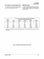
Table 4-1 shows welding lead sizes recommended
for various lengths of leads. The footage shown
includes complete welding circuit, both electrode
and work leads.
12. Carefully read and follow "Operating Instruc-
tions" in your engine operator's manual.
TOTAL LENGTH OF LEAD CIRCUIT IN FEET (AND METERS)
Welding (ELECTRODE LEAD PLUS WORK LEAD)
Current 50 Feet 100 Feet 150 Feet 200 Feet 250 Feet
Amperes (15.2 M) (30.5 M) (45.7 M) (61.0 M) (76.2 M)
100 #4 #4 #2 # 1 #1
150 #2 #2 #1 # 1/0 # 2/0
200 # 1 # 1 # 1/0 # 2/0 # 3/0
250 # 1/0 # 1/0 # 2/0 # 3/0 # 4/0
300 # 2/0 # 2/0 # 3/0 # 4/0 2-#2/0
350 # 3/0 # 3/0 # 3/0 2 -#2/0 2-4 3/0
400 H 4/0 # 4/0 # 4/0 2 -#2/0 2 -#3/0
NOTE: Cable size shown is for 90°C (194°F) cable insulation, 30°C (86°F) ambient, and not over 4.5 volts
cable drop.
Table 4-1 Suggested Copper Welding Lead Size Guide
August 24, 1998
430429-427
INSTALLATION
This page intentionally left blank.
4-4 August 24, 1998
OPERATION
430429-427
OPERATION
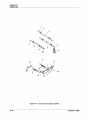
WARNING: MA-4030D mounted on a trailer may develop a rough' running
low idle. Normal idle speed is around 1300 RPM. When mounted on some
trailers, the unit will interact with the trailer leaf springs and tires and cause
it to run rough. To eliminate, adjust the idle screw on the injection pump (see
Figure 5-1) by turning either clockwise or counterclockwise to raise or lower
the low idle speed. Be sure, however, not to adjust the low idle below 1000
RPM as the generator will not operate properly.
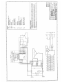
Figure 5-1
Prestarting Instructions
In all probability, the welding unit will be moved
from one location to another many times during its
lifetime of service. Therefore, reference to Initial
Preparation For Use located in Installation chapter
is suggested each time the unit is moved prior to
using it.
1. Check the supply of fuel, crankcase oil and
radiator coolant. See Perkins Engine Handbook for
specifications.
2. Inspect the unit thoroughly to be sure it is in
proper working order. Check all fuel line and wire
connections to be certain they are secure. Tighten
any loose screws, nuts or bolts.
3. Wipe off the entire unit and clean the air pas-
sages, control box and hard-to-reach places with
compressed air not over 25 psi (172 kPa).
4. Make sure that no loose bars, tools, parts, etc.,
are in or on any part of the engine as they could
August 24, 1998
5-1
430429-427
OPERATION
cause serious damage to the engine, generator, or
personal injury to anyone standing nearby.
5. Ifthe unit is operated indoors, make sure that an
exhaust line is properly connected to the engine
exhaust system, and discharges out of doors. Avoid
short bends or reduction in line size in exhaust
pipes, and locate the unit so as to necessitate the
shortest possible exhaust line to insure the least
amount of back-pressure on the engine. Back-pres-
sure can cause engine damage and loss of power.
6. Attach welding leads, as described under Initial
Preparation For Use located in Installation chapter.
Observe Table 4-1 and determine that welding leads
are proper size for amperage being used for weld-
ing.
Break-in Procedures
A proper break-in procedure for a new diesel en-
gine-driven welding generator is extremely impor-
tant to avoid future problems. Long periods of
operation at idle or light load condition may result in
cylinder wall "glazing" and resultant poor seating of
piston rings so that oil consumption will be exces-
sive. Also, it may result in "wet stacking”, which is
unburned fuel that accumulates in the exhaust pipe
due to extremely low exhaust temperatures. The
following procedure will apply a load to the engine,
assuring the hot exhaust [at least 450°F (232°C)],
which will aid in preventing "wet stacking”.
1. Open the fuel shut-off valve at fuel tank.
2. Start the engine (see instructions under Engine
Controls and Instruments included in Description of
Equipment chapter) and let it idle for a few minutes
to warm up lubricating oil and coolant, and then shut
the engine off.
NOTE: Idling RPM is approximately 1300.
3. Check engine for low oil pressure, leaks or
malfunctioning parts. If oil pressure does not show
a sufficient, steady pressure within 5 seconds, shut
engine down and determine cause.
4. Start engine again. Pull throttle control handle
all the way OUT. Operate unit with canopy doors
closed.
NOTE: Covering the radiator partially with
cardboard or plywood during this operat-
ing period will speed up the engine warm-
up. Care must be taken, however, to avoid
overheating and boiling the coolant in the
radiator.
5. Apply a load to the welding generator. This can
be accomplished by attaching a proper resistance
load across the welding terminals and setting the
current control. The load should be equal to at least
one-half of the normal full load output of the unit
(rated 300 amps/40 volts).
6. Operate the engine-generator unit for approxi-
mately one hour under the above loading condi-
tions.
NOTE: This procedure can be followed at
any time that wet-stacking becomes a
problem, in order to burn out the unburned
hydrocarbons that accumulate in the ex-
haust stack.
Prewelding Instructions
To adjust weld current and arc characteristics
while welding, the High/Low Range Switch, Current
Control, and Arc Force Control can all be adjusted
under load, without damaging the welding ma-
chine. However, caution should be used in switch-
ing from low to high range on the Range Selector
Switch, as this would cause the welding current to
be immediately doubled. This might be more than
the electrode in use could stand. This would cause
immediate problems with the welding arc.
Note that on the Current Control dial, the low range
is just one-half of the high range values. For exam-
ple, leaving the Current Control setting constant, the
high range would deliver 200 amperes, and the low
range 100 amperes. This relation holds consistent
through the entire range of the welding machine,
giving two widely overlapping current ranges. The
low range is 15 to 200 amperes, and the high range
is 30 to 400 amperes. The entire usable range of the
machine for stick electrode (SMAW) welding can be
obtained in the single high range.
Adjustable Arc Force control for the welding proc-
ess gives the operator great flexibility in selecting
the arc characteristics needed for a particular job.
(Refer to Volt-Amp Curves in installation chapter.)
Setting the Arc Force Control at 4 to 6, or in the
FORCEFUL range will adjust the welding charac-
teristics of the machine to be normal and similar to
many of the conventionally controlled engine-driven
stick-electrode welding machines. However, turning
down the Arc Force Control to the 2 to 4, or
SMOOTH range, gives a softer, less "spatter" type
of welding arc. Setting the Arc Force Control to
DIGGING, 6 to 10 range, gives a very forceful, driv-
August 24, 1998
430429-427
OPERATION
ing arc, which makes "sticking" the electrode nearly
impossible.
Note on the Volt-Amp Curves that this adjustment
of arc characteristics is accomplished by changing
the short-circuit-to-welding current ratios as indi-
cated by the dotted lines for arc force settings of O,
2, 5, and 10 on the dial.
Welding
After ail Prestarting and Break-In Procedures have
been carried out, the controis for using the gene-ra-
tor for welding may be set and welding accom-
plished. Follow this procedure:
1. Start engine per above instructions. Operate unit
with canopy doors closed.
2. Set Range Selector Switch on desired range and
adjust current control for desired current. Turning
the current control clockwise increases the welding
current and open-circuit voltage; while turning it
counterclockwise decreases the welding current.
3. Strike an arc and begin welding. If a change in
welding current is desired, increase by turning knob
clockwise until desired current is obtained. See
Prewelding Instructions above for details on current
range, current level, and arc force control.
Stopping The Engine
1. Stop welding.
2. Push the throttle control handle IN towards the
panel as far as it will go.
3. Allow engine to cool sufficiently, then check
coolant and crankcase oil level. If engine oil is to be
changed, it can be done most effectively while en-
gine is still warm.
CAUTION: Use extreme care when re-
moving a radiator cap from an over-
heated engine. Turn the cap only to the
first notch, and allow steam to escape
before removing the cap completely.
4. After engine has cooled completely, fill the fuel
tank. See Safety Warnings chapter included in this
manual for precautions that should be taken when
filling the fuel tank.
Storage
Nightly — After operation, the following steps
should be taken before storing the welding machine
for short periods of time.
1. Clean up around working area. Put all tools,
parts and supplies in their proper places.
2. Disconnect welding leads from machine. Coil
them and stow away in their place.
3. lf unit is to be stored outdoors, it is wise to cover
it with a tarpaulin.
Extensive Storage Time — If unit is to be laid-up
for some time, please refer to Withdrawing An En-
gine From Service, in Maintenance Section of
Perkins Handbook for Diesel Engines, which is sup-
plied with each unit.
Adverse Weather Precautions
Cold Weather Operation — Operation of engine-
driven welding units at sub-zero temperatures re-
quires special precautions and extra servicing from
both operation and maintenance personnel if poor
performance or total functional failure is to be
avoided. Consult Engine Workshop Manual and rec-
ommendations below.
a. Fuel System — Keep system clean and free
from water which may collect in alow spot in the fuel
line and freeze, plugging the line. Fuel tanks should
be kept FULL to prevent water condensation from
the air above the fuel. Check the filter bowl daily for
presence of water.
b. Fuel — Keep fuel storage tanks or drums as
full as possible to avoid condensation of moisture
from the air above the fuel. After filling or moving fuel
containers, allow fuel to settle before using. Never
draw fuel from the extreme bottom of the container.
Strain all fuel to remove any foreign matter. When
operating outdoors, take steps to prevent the entry
of snow, water and ice into the fuel containers.
c. Cooling System — Prior to cold weather, drain
ad flush the cooling system to remove accumula-
tions of rust and sediment. Mix and add antifreeze
solution, check the cooling system connections for
leaks. Add a can of rust inhibitor to the radiator
when system is winterized. This will keep system
cleaner and furnish lubrication for the water pump.
d. Lubrication — Drain the crankcase (prefer-
ably when warm after running) and fill with a lighter
grade of oil. See Engine Oil Recommendations chart
in the Maintenance and Operators Manual for rec-
ommended viscosity oil for various atmospheric
temperatures. In cold weather, drain oil more fre-
quently. Water condenses and collects quickly,
mixes with the oil and increases deposits to form a
sludge. Check oil frequently for this condition. Water
in crankcase or oil lines may freeze and cause
August 24, 1998
5-3
430429-427
OPERATION
serious damage to the oil pump, or shut off the oil
supply.
e. Battery — Battery efficiency decreases
sharply with lower temperatures. Maintain the spe-
cific gravity of the battery between 1.275 and 1.300
(fully charged condition). Make sure of full charge
before attempting to start engine in sub-zero condi-
tions.
Operation in Hot And Humid Conditions
a. Cooling System — Elevate welding machine
6 to 8 inches (150 to 200 mm) above floor or ground
level to provide adequate circulation of air. Maintain
a more frequent check of the coolant level in the
radiator.
b. Battery — The specific gravity and proper
level of the battery electrolyte should be maintained.
Observe recommendations in the Maintenance and
Operator's Engine Manual for proper care of the
battery.
Operation In Extremely Dusty Conditions — If
unit is to be operated under dusty, out-of-door con-
ditions, place in a sheltered area. Take advantage of
any natural barriers which may offer protection from
blowing dust. If the installation is more than tempo-
rary, erect a protection shield.
a. Fuel System — Drain the fuel water-trap sedi-
ment bowl frequently, and keep all fuel containers
covered and protected against dust entry.
b. Oil Filter and Air Cleaner — These both need
more frequent attention under dusty conditions.
Check air cleaner dally. Replace oil filter cartridge
as needed. Change element in the air cleaner as
required.
с. Crankcase — The crankcase oil level will bear
close attention. Dusty conditions tend to load crank-
case oil with dirt. Watch for dirty and gritty oil con-
ditions, and change oil more frequently as required.
Operation In Salt Water Areas
a. Canopy — Wash canopy regularly to remove
salt film. Repaint any damaged places and oil the
side panel hinges regularly.
b. Covering — To protect the engine and gener-
ator as much as possible from salt water atmos-
phere, keep the side panels on the canopy closed,
when not in use. lt is advisable to keep the unit
covered with a tarpaulin, if available, while not in
operation. Salt water should be wiped from the
engine, and all terminals and connections in the
electrical system wiped dry. Keep all linkage oiled.
c. Brushes — The brushes of the welding gener-
ator and exciter should be inspected regularly to
make certain that they are free in the holders. Lift the
brushes in the brushholders about every two days,
to insure their freedom to slide within the holder.
Wipe dry all the parts that can be reached, and use
compressed air, if available, to dry the parts of the
generator that cannot otherwise be reached. See
Maintenance chapter for brush and commutator
care.
d. Field Coils — The fields should be dried as
thoroughly as possible. If they have become damp,
proceed with recommended procedure in Mainte-
nance chapter.
e. Battery Terminals — Thoroughly clean the
battery terminals and connections. Coat terminals
and connections with petroleum jelly to retard cor-
rosion.
5-4
August 24, 1998
430429-427
MAINTENANCE
MAINTENANCE
Engine And Related Components
NOTE: Check Detroit Diesel/Perkins Hand-
book for Diesel Engines for all engine-re-
lated maintenance.
Inspection And Cleaning
Every Day, check for oil, coolant, or fuel leaks.
Also check for loose electrical connections. Check
oil pressure with engine running at rated RPM (1800
RPM). Do not operate engine if oil pressure light
stays ON. Wipe accumulated water off all electrical
connections and instruments. Make sure that the
alternator light is not glowing, which indicates bat-
tery is being fully charged.
Every Week, wipe accumulated dust, dirt, and oil
off from the engine and generator. Check all parts
for looseness and wear. If arcing has occurred at
any electrical connection, recondition it and se-
curely refasten. Check engine oil and coolant levels.
Every Month, blow out generator windings with
compressed air, not over 25 psi (172 kPa) pressure
or remove with a suction type cleaner with a non-
metallic nozzle. If windings should become slightly
damp, use space heaters or electric light bulbs to
effectively dry out the windings. If dampness is
excessive, apply external heat under a canvas
cover, wellvented. Heating should notexceed 194°F
(90°C).
Pound out any dents in the canopy. Sand, prime,
or repaint any dented or rusted spots.
Lubrication
Engine — Consult Perkins Handbook for Diesel
Engines.
August 24, 1998
6-1
430429-427
MAINTENANCE
This page intentionally left blank.
6-2 August 24, 1998
430429-427
TROUBLESHOOTING
TROUBLESHOOTING
The following chart contains information which can be used to diagnose and correct unsatisfactory opera-
tion or failure of the various components of the welding generator. Each symptom of trouble is followed by
a list of probable causes and the procedure necessary to correct the problem.
Troubleshooting Guide
No output at 115-V and 230-V Receptacles or Welding Terminals (Unit won't build
up voltage)
Loose connections.
Check connections completely.
Broken wiring.
Repair.
No output at welding terminals (115-V and 230-V receptacle output OK).
Shorted power diode SCR, or flyback diode in output rectifier assembly.
Replace defective device.
Fuses to control P.C. Board blown.
Replace fuses.
Control P.C. Board failure.
Replace P.C. Board.
Output voltage too high.
Engine overspeeding.
Check engine RPM; should read 1825-1840 (no load).
Output voltage too low.
Engine running underspeed.
Check engine RPM.
Engine
See Detroit Perkins Handbook For Diesel Engines.
August 24, 1998 7-1
430429-427
~ TROUBLESHOOTING
Detailed Troubleshooting
Instructions
The Mega-Arc* 4030D machines are solid-state
welding machines. The method of troubleshooting
is different, but it is not more difficult than trou-
bleshooting a conventional unit. Do not overlook the
obvious. As in the case of all electrical equipment,
loose connections are the primary cause of mal-
function both internal and external to the power
source. Do not overlook bad grounds, shorted con-
trol cables, wrong settings, blown fuses, miscon-
nections from auxiliary equipment, misapplications,
etc. The only equipment needed to properly detect
a problem on this power source is a simple vol-
tohmmeter, although an oscilloscope is the best
method to quickly "see" the problem.
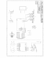
Voltages — Refer to proper connection diagram.
See Diagram chapter included in this manual.
The following voltages should be read at 1800 RPM
engine speed.
1. Welding circuit phase-to-phase, on all three
phases — 60 VAC + 10%.
2. Check for blown fuses F3-F8. Refer to Connec-
tion Diagram. Between wires 13 brown, 14 orange,
15 grey, 16 black, 17 yellow, and 18 blue on fuse
block — 60 V AC + 10%.
NOTE: The + 10% value indicates the pos-
sibility of having a high or low engine RPM.
Malfunction In SCRs Or Diodes — The following
conditions will probably exist:
1. One SCR does not turn on (either it is open, or
gate signal is not being received by the SCR [gate
circuit open]) and a very small change will occur at
the welding arc, and will be difficult to detect by the
average welding operator. Generally when this hap-
pens, it will be necessary to adjust the current con-
trol on the front of the power source (see Figure 3-1),
increasing the current to obtain the same welding
current that was being produced before the SCR
defect occurred.
Open-Circuit Voltage Test
If the power source is suspected, a very simple test
can tell you a great deal about the power source.
Observe the open-circuit voltage of the machine by
placing a voltmeter across the output terminals. The
voltage reading should be approximately 75 V DC.
If the voltage is not equal or close to 75 V DC, there
is something wrong with the power source (welding
machine). Note that this voltage was observed at
normal engine speed (1800 RPM). It will vary ac-
cording to the engine speed. If the 75 V DC is
observed, there is a very good chance that the
power source is operating properly.
NOTE: It is important to note that in the LOW
range (15 to 200 amperes) at minimum
setting of the Current Control, the open-cir-
cuit voltage will drop to a lower value and
vary slightly with the current control. This is
not a malfunction, but a normal situation.
Power Diode And SCR Testing
In case of a severe malfunction such as a shorted
SCR, do NOT turn the unit ON. Disconnect the leads
from the generator to the rectifier assembly, and
check with a VOM for shorted SCRs and diodes.
An open gate or an open SCR cannot be checked
with a VOM. If an SCR is not firing, the open-circuit
voltage will shift down. Check the following table for
typical values for a Mega-Arc® 4030D unit.
All Three
SCRs | One Not | Two Not Not
Firing Firing Firing Firing
Max
OCV 75VDC 50VDC 25VDC OVDC
Table 7-1
NOTE. The above values in Table 7-1 were
recorded at normal engine RPM (1800).
Isolating Malfunctioning SCR
This can be done best by trial-and-error method.
Use proper diagram as reference while inspecting
the unit.
On the output rectifier heat sink there are three
SCRs, each having two small leads. The leads, a
white and red one, are connected to a wire harness
providing the gate signal to the SCRs.
Turn the Current Control to maximum position
(fully clockwise) and begin disconnecting the white
leads from the harness, one at a time. As the first
lead is disconnected, observe the open-circuit volt-
age of the machine. If the OCV drops to a lower
value, it will indicate that this particular SCR is work-
ing properly. Reconnect this lead, and proceed to
do the same with the remaining two leads until you
discover which disconnection does not cause the
OCV to drop to a lower level. This will be the SCR
which should be changed.
7-2
August 24, 1998
Printed Circuit Board Testing
The next step is to check the Printed Circuit Board
inside the unit. See Figure 7-4 and Table 7-2 for
location of test points and voltage values at the test
points.
The following conditions indicate the possibility of
a defective P.C. Board:
1. Loss of welding arc completely.
2. Rough, sputtering arc, very noticeable.
3. Loss of welding arc control.
4. Difficulty in starting arc.
If any voltage measurement does not agree with
Table 7-2 voltage values, the P.C. Board is probably
defective.
NOTE: Do not attempt to repair or recali-
brate these voltages, as they are factory
set.
Mounting Procedure for SCRs
1. Thoroughly clean heat sink surface to eliminate
any dirt or contamination.
430429-427
TROUBLESHOOTING
2. Apply a thin coat of Alcoa #2 compound to
cleaned surface. Alcoa # 2 is available from Thermal
Arc, part number 903870.
3. Positively locate the SCR in place in the heat
sink. A small spring pin in the extruded heat sink will
locate the SCR.
4. Place the clamp in position with the bolts
through the holes in the heat sink, and proceed in
following manner.
5. Tighten the nuts evenly until finger tight.
6. Tighten each bolt in 1/4 turn increments using
correct size hex key.
7. Place the Force Indicator Gauge (903878) firmly
against the springs as shown. Be sure both ends and
the center are in firm contact with the springs. The
gauge notch location will indicate the spring deflec-
tion or force. Correct mounting force is indicated as
shown below.
8. Spring deflection over 2-1/4 inches of spring is
037" + .002" for all clamps.
9. All clamps to be set at 4° mark. This corresponds
to the VE3000-VE2500 section on the gauge label.
August 24, 1998
430429-427
TROUBLESHOOTING
— Force Gage, shown 1
position (003878)
Clamp(405140)
Neal Sink
а Sink
| A-487 |
Figure 7-1
To Calibrate Force Gauge:
Examples:
Less than rated
force. Tighten
nuts alternately
1/4 turn at a time
until points coin-
cide.
Correct rated
force.
Figure 7-2
Top edges lined up
Excessive
force. Loosen
both nuts and
start over.
Never adjust
force by back-
ing off the nuts.
Friction will
produce a false
reading. AL
ways start from
Step 1.
If the gauge is suspected of being out of calibration due to wear or damage, check it on a flat surface as
shown below.
E
=
=
True flat surface
(or straight edge)
See
| A-489 |
if the calibration edges do not line up, mol the
gauge by filing the bottom contact points.
Figure 7-3
7-4
August 24, 1998
430429-427
TROUBLESHOOTING
14 1 2
| / /
© ABER BE ENERO ERAN = АННЕ REPO ©
O Z 1 я 1 6 1 O
_
“ae
13 | ©
.
У +
12
11 =
4
MP
< =
< Il
7 = |=
8 = |->
0 = |
TP
65 — IE
O
O ‘09 "SOME JMVEOH ©
491238
Figure 7-4 Control P.C. Board
TEST TEST POINTS | CALLOUTS VOLTAGE CONDITIONS REMARKS
1 TP-N to TP-E 2 to 13 +40.0/+21.0 1800 RPM/idie No Load
2 TP-M to TP-E 14 to 13 —40.0/-21.0 1800 RPM/Idie No Load
3 TP-C to TP-E 3 to 13 +20.0 1800 or Idie No Load
4 TP-D to TP-E 12 to 13 —20.0 1800 or idle No Load
5 TP-A to TP-E 4 to 13 +15.0 1800 or Idle No Load
6 TP-B to TP-E 11 to 13 —15.0 1800 or Idle No Load
7 TP-F to TP-E 5 to 13 +4.3 1800 or Idle No Load
TP-G to TP-E 7 to 13 +4.3 1800 or Idle No Load
TP-H to TP-E 9 to 13 +43 1800 or Idie No Load
8 TP-J to TP-E 6 to 13 +18.3 1800 or Idle No Load
TP-K to TP-E 8 to 13 +18.3 1800 or Idle No Load
TP-L to TP-E 10 to 13 +18.3 1800 or Idle No Load
Table 7-2
August 24, 1998 7-5
430429-427
TROUBLESHOOTING
This page intentionally left blank.
7-6 August 24, 1998
430429-427
PARTS LIST
PARTS LIST
Equipment Identification
All identification numbers as described in the Intro-
duction chapter must be furnished when ordering
parts or making inquiries. This information is usually
found on the nameplate attached to the equipment.
Be sure to include any dash numbers following the
Specification or Assembly numbers.
How To Use This Parts List
The Parts List is a combination of an illustration
(Figure Number) and a corresponding list of parts
which contains a breakdown of the equipment into
assemblies, subassemblies, and detail parts. All
parts ofthe equipment are listed except forcommer-
cially available hardware, bulk items such as wire,
cable, sleeving, tubing, etc., and permanently at-
tached items which are soldered, riveted, or welded
to another part. The part descriptions may be in-
dented to show part relationships.
To determine the part number, description, quan-
tity, or application of an item, simply locate the item
in question from the illustration and refer to that item
number in the corresponding Parts List.
An “Application Code” is used to distinguish parts
that are applicable only to certain Specifications
and/or Assemblies. This code is found in the right-
most column of the Parts List. If an item in the Parts
List applies to all Specifications or Assemblies, the
word “ALL” will bein the Application Code column.
Refer to the following list to determine the appro-
priate Application Codes for the Specifications or
Assemblies covered by this manual. If only the
assembly or specification number is listed, the use
of an Application Code does not apply to this
manual.
How To Select Recommended
Spares
The first two columns of the Parts List are used to
show the recommended quantity of parts which
are typically required for spares or replacement
purposes. The quantities under Class 1 are for
parts that are consumed or that may need replace-
ment in two years or less depending on operating
hours. Class 2 quantities are for parts that may
need replacement under unusual service condi-
tions or additional operating hours. These are sug-
gested quantities based on expected usage or the
minimum package quantity. Class 1 spares are
repeated under Class 2 but the quantities may be
larger to allow for additional operating hours. Con-
tact your equipment dealer for assistance in estab-
lishing the spare parts program best suited for your
needs.
SPEC NUMBER
6298E-1
August 24, 1998
8-1
430429-427
PARTS LIST
Figure 8-1 Control Panel
Quantity
Recomm. Item Part
Spares No. Number
Class 1 Class 2
Parts List for Figure 8-1
Description
Qty
per
Assy
494119-10
494096-1
404089
403091-4
403091-12
79C-1149-1
494150-1
OO RL ON A
Panel - Control Assembly
. Panel - Control
. Receptacle - Duplex, 3 Wire, 230 V
. Plug - Hole, Plastic
. Plug - Hole, Plastic
. Meter - Engine Hour
. Gauge - Water Temp.
=D — ed == oe —i >
8-2
August 24, 1998
430429-427
PARTS LIST
Parts List for Figure 8-1
Quantity
Recomm. Item Part Description Qty
Spares No. Number per
Class 1 Class 2 Assy
7 406004-1 . Light - Snap Mt., Red 2
8 Deleted
9 403091-2 . Plug - Hole, Plastic 1
10 30GH-1119 . Switch - Pushbutton 1
11 494134-1 . Gauge - Fuel 1
12 404856 . Switch - Toggle, DPDT, MOM, ON 1
13 405982-1 . Cover - Hole, Meter 2
14 402670 . Receptacie - Duplex, 3 Wire 115 V 1
15 409527-3 . Circuit Breaker - Thermal 3
492010-8 . Box - Control, Assembly 1
16 492036-1 .. Box - Control 1
17 406003-2 .. Strip - Terminal Q.C., 12 Station 1
18 406003-1 .. Strip - Terminal Q.C., 6 Station 1
19 404915-1 .. Spacer - P.C. Board 6
20 491238 .. Board - P.C. Control Assembly 1
21 W-11166-9 . Fuse - 1 Amp, Fast Blow 6
22 405129-1 . Block - Fuse 1
23 367579 . Insulator - Fuse Block 1
— 405157 . Label - Fuse 1
491454-1 . Door - Control Box Assembiy 1
24 491446-1 .. . Door - Assembly 1
25 406040 .. Boot - Toggle Switch 3
26 405365-1 .. Switch - Toggle, SPST 1
27 367703-1 .. Resistor - 1/2 Watt Assembly 1
28 406926-1 .. Potentiometer - 2 Watt, 5 K 2
29 492576 .. Board - Mtg. Pot. 1
30 402663 .. Nut - Pot. Lock 2
31 406806-3 .. Knob - Control 1
32 491773-3 . Knob - Control 1
33 8BW-106A .. Spacer 1
34 402682 . Switch - Toggle 2
35 400758 .. Receptacle - 6 Pin Amphenol 1
36 404875 ‚.. Сар & Chain - Assembly 1
37 494097-1 Panel - Rear, Lower 1
38 DW-4333 Rod - Throttle 1
— Not lllustrated
August 24, 1998 8-3
430429-427
430429-427
PARTS LIST
Parts List for Figure 8-2
Quantity
Recomm. Item Part Description Qty
Spares No. Number per
Class 1 Class 2 Assy
800023 Generator - Assembly 1
1 491758-3 Cover - Hole, Flywheel Housing 1
2 800021 Housing - Flywheel 1
3 800042 Coupling - Assembly 1
4 490594 Fan - Coupling 1
5 C-31 Key - Coupling 1
6 800023-5 Armature - Assembly 1
7 800023-7 Bearing - Snap Ring, O-Ring 1
8 800023-2 Cover - Upper Stator 1
9 800023-1 Housing - Gen. Assembly 1
10 800023-11 Screw - Fan 1
11 800023-6 Cooling Fan - Generator 1
12 800023-3 Cover - Lower Stator 1
August 24, 1998 8-5
430429-427
PARTS LIST
Figure 8-3
August 24, 1998
8-6
430429-427
PARTS LIST
Parts List for Figure 8-3
Quantity
Recomm. Item Part Description Qty
Spares No. Number per
Class 1 Class 2 Assy
1 492364-3 Top - Canopy 1
2 409158 Label - Danger 1
3 405089 Label - Fuel 1
4 406000 Label - Warning, Fuel 1
5 494445 Label - Precautionary 1
6 494130 Shield - Safety 1
7 494133 Cap - Fuel Tank 1
8 DDW-495-8 Cap - Rain 1
9 407366 Label 1
10 359699-1 Brace - Canopy 2
11 406187 Bracket - Mtg. Air Cleaner 2
12 406927 Cleaner - Air 1
13 W-10869-3 Clamp - Hose 2
14 406945 Hose - Air Cleaner 1
15 491414 Reactor - Stability Assembly 1
16 494127 Tank - Fuel 1
17 494135-1 Sender - Fuel Gauge 1
18 494139-1 Support - Fuel Tank 1
19 492191-1 Panel - Heat Shield 1
20 491820-1 Support - Heat Shield 1
21 492195 Cover - Heat Shield 1
22 406358-2 Resistor - Preload 1
23 494456-1 Yoke - Lifting, Assembly 1
24 402037-11 Grommet - Lifting Yoke 2
25 482367-1 . Plate - Rect. Output, Right 1
26 492366 . Plate - Rect. Output, Left 1
1 1 27 W-10931-3 . Rectifier - Silicon Controlled 4
1 1 28 405140-1 . Clamp - Mounting 3
29 492413 . Heat Sink - SCR 3
30 405826 . Rectifier - Silicon Controlled 3
— 16DA-954-12 . Pin - Spring 3
31 494459-1 . Spacer - Insulating 2
32 4102236 . Tubing - Fiber 2
33 494459-8 . Spacer - Insulator 2
34 494459-2 . Spacer - Insulator 2
4925336 Panel - Terminal Assembly 1
— Not illustrated
August 24, 1998 8-7
430429-427
PARTS LIST
Parts List for Figure 8-3
Quantity -
Recomm. Item Part Description Qty
Spares No. Number per
Class 1 Class 2 Assy
35 492532-2 . Panel - Output Weld 1
36 5CW-974 . Bar - Bus 2
37 No Number . Nut - 1/2-13, HWH, ST. 2
38 5CW-975 . Bushing - Insulator 2
39 5CW-976A . Washer - Insulating 4
40 No Number . Washer - 1/2 FL. ST. 2
41 No Number . Washer - 1/2 LK. ST. 5
42 351505 . Screw - 1/2-13 x 1-3/4 2
43 368705-7 . Capacitor - Assembly 2
44 No Number . Screw -# 6-30 x 3/16 Rd. Hd. MH. 2
45 No Number . Washer - 1/2 FL. ST. 3
46 367687 . Shunt 1
— W-9234-338 Cable - Output Term. to Rect. 1
— W-9234-339 Cable - Output Term. to Reactor 1
47 491763-3 Door - Side 2
48 490174 Plate - Hinge 12
49 490040 Hinge - Door 6
50 490234 Latch - Door 4
51 493457 Spacer - Latch 4
52 492244 Handle - Door Latch 4
53 406155 Muffler 1
54 406080 Engine - Diesel 1
55 W-10750-2 Nipple - Pipe 1
56 W-10910-0 Tee - Pipe, 1/8 1
57 402130 Switch - Oil Pressure 1
58 409159 Switch - Oil Pressure 1
— 494824 Spacer - Fan 1
59 491673-2 Support - Engine 2
60 491672-1 Spacer - Mtg. Engine 2
61 406178 Label - Oil Filter 1
62 494128-1 Panel - Side, Right 1
63 409554-1 Rectifier - Assembly 1
63A 202258-5 Suppressor - W/Lugs 1
64 367634A-5 Suppressor - Surge Assembly 1
65 492049 Bracket - Mtg. Bus Bar 1
66 492047 Bar - Bus 1
— 403618-7 Belt - Fan 1
Not lllustrated
August 24, 1998
430429-427
PARTS LIST
Parts List for Figure 8-3
Quantity
Recomm. Item Part Description Qty
Spares No. Number per
Class 1 Class 2 Assy
67 406149 Fan - Engine 1
68 Deleted
69 494181 Alternator - Delco 1
— W-9360-229 Cable - Bonding 1
70 494149-2 Sender - Water Temp. 1
71 No Number Filter - Fuel (Supplied W/Engine) 1
72 491721-2 Bracket - Mtg. Fuel Filter 1
73 492362-3 Panel - Front 1
74 491689-23 Plate - Front End 1
75 491690-2 Support - Radiator 2
76 406981-1 Radiator 1
77 406989 Cap - Radiator 1
78 W-10869-12 Clamp - Hose 4
79 406977 Hose - Radiator, Top 1
80 493252-2 Shroud - Fan 1
81 405977-2 Hose - Radiator Bottom 1
82 494741 Guard - Fan 1
83 406001 Label - Caution 2
84 494725 Brace - Guard 1
85 5CW-1932-0 Block - Drain 1
86 4921334 Cable - Batt. Pos. 1
87 492132-3 Cable - Batt. Neg. 1
88 491962-2 Clamp - Battery 1
89 494295 Rods - Battery 2
90 4911221 Angle - Mtg. Front Panel 2
91 800022 Frame - Mounting 1
92 491683-2 Bar - Mtg. Gen. 1
93 406254-3 Mount - Shock 4
94 491799-1 Washer - Shock 8
95 494129-1 Panel - Side, Left 1
96 402086-2 Battery 1
— 493797-2 Protector - Batt. Term. 1
— 357013 Clamp - Throttle Rod 1
97 494730 Guard - Alternator 1
98 800031 Tray - Capacitor 1
99 800023-10 Capacitors - 60 uF 5
100 800023-9 Capacitors - 70 uF 2
— Not lliustrated
August 24, 1998 8-9
430429-427
PARTS LIST
Figure 8-4 Fuel Lines and Speed Control
8-10 August 24, 1998
430429-427
PARTS LIST
Parts List for Figure 8-4
Quantity
Recomm. Item Part Description Qty
Spares No. Number per
Class 1 Class 2 Assy
492288-1 Line - Fuel & Return 1
1 490036 . Line - Fuel 1
2 W-10869-14 . Clamp - Hose 6
3 355325-10 . Hose - Rubber 1
4 355325-16 . Hose - Rubber 1
5 405091-1 . Elbow - Male, Barbed 1
6 402265 . Valve - 1/4 Turn, Shut Off 1
7 492075 . Line - Return 1
8 4918894 . Hose - Rubber 1
9 4029271 . Adapter - Tube to Pipe 1
9A 12CW-2125 . Elbow - Street, 45° 1
Speed Control Section
10 490186 Arm - Fuel Shut-Off 1
11 400562-32 Spring 1
12 490028 Pivot - Throttle 2
13 16DW-34 Bushing - Throttle 2
14 494541 Clamp - Throttle Rod 1
15 490010-1 Support - Throttle Rod 1
16 492360-1 Bracket - Spring 1
17 W-799F-110 Spring 1
— 490073-1 Bracket - Spring 1
— Not illustrated
August 24, 1998 8-11
430429-427
PARTS LIST
This page intentionally left blank.
8-12 August 24, 1998
EAST PENN manufacturing co. inc.
- Material Safety Data Sheet -
BATTERY FLUID ACID
8 UN2796 РСП
Manufacturer's Name: Date Prepared: Revised April 1994
East Penn Manufacturing Co. Inc.
Deka Road, Lyon Station, PA 19536
Telephone Number for Information: (610) 682-6361
Emergency Telephone Number: CHEMTREC: 1-800-424-9300,
, cali 1-202-483-7616
Hazardous Components
Other Limits
Specific Chemical Identity
(Common Маше (5) OSHA PEL ACGIH TLV Recommended Percent
| |
30
|
N/A
1.00 mg/m’ 1.00 mg/m’
Appearance and Odor: clear, odorless, colorless Solubility in Water: completely
Boiling Point: approximately 235°F Specific Gravity (H,0=1): 1.220-1.325
Evaporation Rate (Butyl Acetate=1): less than 1.0 Vapor Density (AIR=1): N/A
Melting Point: N/A 13
Flash Point (Method Used): non-flammable Flammable Limits: N/A
Extinguishing Media: N/A | ТЕТ: UEL:
Sulfuric acid will not burn but is capable of igniting
Special Fire Fighting Procedures:
Combustibles may be smothered by dry chemical
finely combustible material on contact.
extinguishing media.
H=3,
NFPA ratings:
F=0, R=
Unusual Fire and Explosion Hazards:
TY DATA (Battery
Stability: Stable Condition to Avoid: Contact with metal may release explosive
hydrogen gas.
Incompatibility (Materials to Avoid): Strong alkali materials, carbides, chlorates,
nitrates, and pierates, organic acid, acetates, anhydrites.
Hazardous Decomposition of By-Products: Thermal decomposition or combustion may produce a
sulfur trioxide and/or sulfur dioxide.
Hazardous Polymerization: will not occur
Page 1 of 2
MSDS: Battery Electric Storage, Dry; page 2 of 2
Route (s) of Entry: No applicable under normal use
Health Hazards (acute and chronic): Internal components contain lead. Repeated or
prolonged exposure to lead can result in lead poisoning. Lead accumulates in the bone and
body organs and is eliminated from the body slowly. (Ref: 29 CFR 1910.1025)
Carcinogenicity: N/A
IARC Monographs: Group 2B carcinogen
OSHA Regulated: 29CFR1910.1025
Medical Conditions Generally Aggravated by Exposure: Pregnant women and children must be
protected from lead exposure.
Signs and Symptoms of Exposure:
Short term: Skin and eye irritation, headache, nausea, vomiting, abdominal spasms, fatigue,
weight loss, anemia, pain in legs, arms, and joints.
Long term: CNS damage, kidney disfunctions and potential reproductive hazard. Symptoms of
lead exposure can be confirmed by the presence of elevated levels of lead in blood.
Emergency and First Aid Procedures: Not applicable under normal use. If lead exposure is
suspected, see
Steps to be Taken in Case Material is Released or Spilled: Avoid contact with internal
components. (See Section VI Health Hazards: Lead)
Waste Disposal Method: Lead acid batteries are completely recycable. For information on
returning batteries to East Penn for recycle, call (610) 682-6361.
Precautions to be Taken in Handling and Storing: N/A Other Precautions: N/A
Respiratory Protection (Specific Type): For specific information see 29CFR 1910.1025, Lead
Exposure
Ventilation: Local exhaust:
Mechanical (general):
Special:
Other:
Protective Gloves: N/A
Eye Protection: N/A
Other Protective Clothing or Equipment: N/A
Work/Hygienic Practices: Always practice good personal hygiene habits and safe work
practices. |
Shipping Name: Battery, dry
Identification Number: N/A, non-assigned
Hazard Class: N/A. This article is not applicable to 49CFR 172.101 Hazardous Materials and
not subject to Parts 170-189 of this sub chapter.
U.S. Postal Service Regulations: unrestricted
20>;
EAST PENN manufacturing co.. inc. e
- Material Safety Data Sheet -
BATTERY WET, FILLED WITH ACID
Manufacturer's Name: Date Prepared: Revised April 1994
East Penn Manufacturing Co. Inc.
Deka Road, Lyon Station, PA 19536
Telephone Number for Information: (610) 682-6361
Emergency Telephone Number: CHEMTREC: 1-800-424-9300,
In Washington D.C. or outside continental U.S., call 1-202-483-7616
Hazardous Components
Specific Chemical Identity Other Limits
(Common Name(s) OSHA PEL ACGIH TLV Recommended Percent |
Lead, CAS #7439921 0.05 mg/m’ 0.15 mg/m’ — N/A 43-70
Sulfuric Acid, CAS #7664939 1.00 mg/m’ 1.00 mg/m’ N/A 20-44
Antimony, CAS #7440360 _ © 0.50 mg/m’ 0.50 mg/m’ N/A 0-4
Appearance and odor: clear, odorless, colorless Solubility in Water: completely
Boiling Point: approximately 235°F Specific Gravity (H,0=1): 1.220-1.325
Evaporation Rate (Butyl Acetate=1): less than 1.0 Vapor Density (AIR=1): N/A
Melting Point:
N/A Vapor Pressure (mm Hg.): 13
Flash Point (Method Used): non-flammable Flammable Limits: *hydrogen gas
Extinguishing Media: Class ABC extinguisher, CO, and/or Halon LEL: 4% UEL: 74%
Special Fire Fighting Procedures: Cool exterior of battery if exposed to fire to prevent
rupture. The acid mist and vapors in a fire situation are corrosive. Wear special
respiratory protection (SCBA) and clothing.
Unusual Fire and Explosion Hazards: *Hydrogen gas, which may explode if ignited, is
produced by this battery, especially when charging. Use adequate ventilation, avoid open
flames, sparks, or other sources of ignition.
Stability: Stable condition to Avoid: Cases decompose at 160-410°C (322-770°F)
Incompatibility (Materials to Avoid): Strong oxidizing agents such as hot nitric acid, etc.
Hazardous Decomposition of By-Products: Combustion can produce carbon dioxide (CO?) and
carbon monoxide (CO).
Hazardous Polymerization: will not occur Conditions to Avoid: not applicable
Page 1 of 2
MSDS: Battery Wet Filled with Acid, 8 UN2794 PGIII; page 2 of 2
Route(s) of Entry: Inhalation, skin contact, and ingestion
Health Hazards (Acute and Chronic): Short term exposure: Sulfuric acid may cause
irritation of eyes, nose, and throat. Prolonged contact may cause severe burns.
Long term exposure: Repeated contact causes irritation and skin burns. Repeated exposure
to mist may cause errosion of teeth, chronic eye irritation and/or chronic inflammation of
the nose, throat, and bronchial tubes. a
TARGET ORGAN: respiratory system, eyes, skin, & teeth Carcinogenicity: N/A
Signs and Symptoms of Exposure: Acid contact may cause irritation of eyes, nose and throat.
Breathing of mist may produce respiratory difficulty. Contact with eyes and skin causes
irritation and skin burns. Sulfuric acid is a CORROSIVE chemical.
Medical Conditions Generally Aggravated by Exposure: Pulmonary edema, bronchitis, emphysema,
dental errosion, and traceobronchitis
Emergency and First Aid Procedures:
1) Flush contacted area with large amounts of water for at least 15 minutes. Remove
contaminated clothing and obtain medical attention.
2) If swallowed, give large volumes of water. DO NOT induce vomiting, obtain medical
treatment. |
3) Eyewash and shower stations should be made available,
Steps to be Taken in Case Material is Released or Spilled: SULFURIC ACID: Dilute spill
cautiously with five to six volumes of water and gradually neutralize with sodium
bicarbonate, soda ash or lime. When exposure level is not known, wear NIOSH approved
positive pressure self-contained breathing apparatus. (Reference DOT UN2796)
Waste Disposal Method: Lead-acid batteries are completely recyclable. For information on
returning batteries to East Penn for recycling, call (610) 682-6361.
Precautions to be Taken in Handling and Storing: Store away from reactive material as
defined in Section V, Reactivity Data.
Other Precautions: Sodium bicarbonate, soda ash, sand, or lime should be kept in same
general area for emergency use. See Section IV on generation of hydrogen gas. If battery
case is broken, avoid direct contact with internal components.
Respiratory Protection (Specific Type): Acid gas respirator required when PEL is exceeded
or employee witnesses respiratory irritation. (See Section VI, Health Hazard Data).
Ventilation: Must be provided when charging in an enclosed area. 29CFR1910.178(g) and
-305(3) (7)
Mechanical (general): acceptable at 1 to 4 air exchanges/hour or to maintain air
concentrations below the PEL.
Local exhaust: preferred
Special:
Other: local building/fire codes may require explosion proof fans and
equipment
Protective Gloves: acid resistant (for example, rubber)
Eye Protection: preferred
Other Protective Clothing or Equipment: acid resistant aprons, boots, and protective
clothing
Work/Hygienic Practices: Good personal hygiene and work practices are mandatory.
EAST PENN manufacturing co.. inc. A
- Material Safety Data Sheet -
ECTRIC STORAGE, DRY
Manufacturer's Name: Date Prepared: Revised April 1994
East Penn Manufacturing Co. Inc.
Deka Road, Lyon Station, PA 19536
Telephone Number for Information: (610) 682-6361
Emergency Telephone Number: CHEMIREC: 1-800-424-9300,
In Washington D.C. or outside continental U.S., call 1-202-483-7616
Hazardous Components
Specific Chemical Identity
(Common Name(s) OSHA PEL
Other Limits
Recommended Percent
Lead and Lead Components
Appearance and Odor: N/A Solubility in Water: N/A
Boiling Point: N/A Specific Gravity (H,0=1): N/A
Evaporation Rate (Butyl Acetate=1): N/A Vapor Density (AIR=1): N/A
Melting Point: N/A Vapor Pressure (mm Hg.): N/A
Flash Point (Method Used): N/A Flammable Limits: N/A LEL: N/A UEL: N/A
Extinguishing Media: Dry chemical, carbon dioxide, water spray or foam
Special Fire Fighting Procedures:
Stability: Stable Conditions to Avoid: N/A Incompatibility (Material to Avoid): N/A
Hazardous Decomposition of By-Products: N/A Hazardous Polymerization: will not occur
Page 1 of 2
MSDS: Battery Fluid Acid, 8 UN2796 PGII; page 2 of 2
Route(s) of Entry: Inhalation, skin contact, and ingestion Carcinogenicity: N/A
signs and Symptoms of Exposure: Acid contact may cause irritation of eyes, nose and throat.
Breathing of mist may produce respiratory difficulty. Contact with eyes and skin causes
irritation and skin burns. Sulfuric acid is a CORROSIVE chemical. SE
Medical Conditions Generally Aggravated by Exposure: Pulmonary edema, bronchitis, emphysema,
dental errosion, and traceobronchitis | —-
Health Hazards (Acute and Chronic):
Short term exposure: Sulfuric acid may cause irritation of eyes, nose, and throat.
Prolonged contact may cause severe burns. ‘
Long term exposure: Repeated contact causes irritation and skin burns. Repeated exposure
to mist may cause errosicn of teeth, chronic eye irritation and/or chronic inflammation of
the nose, throat, and bronchial tubes.
TARGET ORGAN: respiratory system, eyes, skin, & teeth
3) Eyewash and shower stations should be made available.
Emergency and First Aid Procedures:
1) Flush contacted area with large amounts of water for at least 15 minutes. Remove
contaminated clothing and obtain medical attention.
2) If swallowed, give large volumes of water. DO NOT induce vomiting, obtain medical
treatment. |
Steps to be Taken in Case Material is Released or Spilled: Dilute spill cautiously with
five to six volumes of water and gradually neutralize with sodium bicarbonate, soda ash, or
lime. When exposure level is not known, wear NIOSH approved positive pressure self-
contained breathing apparatus. (Reference DOT UN2796)
Waste Disposal Method: Neutralize and dispose in accordance with local, state, and federal
regulations.
Precautions to be Taken in Handling and Storing: Store away from reactive material as
defined in Section V, Reactivity Data.
Other Precautions: Sodium bicarbonate, soda ash, sand, or lime should be kept in same
general area for emergency use.
Respiratory Protection (Specific Type): Acid gas respirator required when PEL is exceeded
or employee witnesses respiratory irritation. (See Section VI, Health Hazard Data).
Ventilation: When PEL is exceeded.
Mechanical (general):
Local exhaust: preferred
Special: o
Other: Adequate ventilation to maintain exposure concentrations below the
PEL.
Protective Gloves: acid resistant (for example, rubber)
Eye Protection: Mandatory during handling and transfer of acid (recommend chemical
goggles).
Other Protective Clothing or Equipment: acid resistant aprons, boots, protective clothing,
and face shield
Protective Gloves: acid resistant (for example, rubber)
Work/Hygienic Practices: Good personal hygiene and work practices are mandatory.
430429-427
DIAGRAMS
DIAGRAMS
Note the model and specification number shown on the equipment nameplate.
e locate these numbers in the model and specification number columns below.
e Use only those diagrams and instructions that are applicable.
CONTROL
MODEL SPECIFICATION| CONNECTION BOX ENGINE
NUMBER NUMBER DIAGRAM DIAGRAM DIAGRAM
Mega-Arc 4030D 6298E-1 800045 494699 800045
August 24, 1998
1 | E © { +
"УЗ * Cir OO "AOL FM JD
Nude A NA ¡ÍA Ed y A TAM Y
SP0008 LOS TACA Y Wi aj pero o pregap “perepuee: pedo y y y 1451 #0 ZADEV
0 0 Bau tC Dinh баб AL pp EERE) Sy fH) — Y Là
“DES EEN
y 10 1 [FIHS GH 580 | 326
He dedo pe Pu MER Ml WO ДНЮ»
ww pe Bupa Baas tu) ли МНС?
SIEHNN NON Y?201 ltd
NOLY NY IJx3 AVEOYIC
99 ISNYHS
AT Jen 3
| 26 -8L-8 |
dell WLU “NO CRA HY rra
TJ | B6- 12-7 | Hrd | УВ
IN am HAT Eté 630
EL LUE 6H 2539
doror NOLDINNOÏ *AYHSWYIO
TUN |:
Id YA
о САО | HAUTE | "ON TriHAN
7 | 00-EZ—7
Sia | AR COTA ALLA AND UN
3NON 100008 Hid 3005 HSINIJ
IRC HOUR TT
I LSO FOSINO
US:
8!
ET
Li
[но (6
DIV)
LAA
MO gl
Fy
“a BL
ÉL
ОМЗ INIDONT
SL
Hd
А
Pa
``
Zu
N
A 1774
SH
A
A8 ++
MB DE
Ma 41
ONZ ONIMVYI9
W-ND 8 73
== rer
9
UL
—
=o co |om [|
Do
La Lal Cal CA CA a Ca Ea
| o
OL
In
1
b
D-
SNe
YIdANS 5S5YHB
430 Mydug
X38 10H NOS
quvos yd
SY0008
G0T0F “NONSINNOS WuovIO | £ TE” | E
FUN
“Ta VA | 04 LOK AMY AOTI SIMIO
SXICATI 04 М THESE)
+i we | Ane | 0e aca | 349305 3SWUOHLO SSTAN
889-172] 2és+o008
TEN | Ma CLA | ADAL AO LOW yea TV
INON 000089 Mid 3005 HSINIJ
Fl WO NAL
[окне кн
SONIONIM
Bd Hal HIMOS ANYNXAY
£91 QONV NOtYLIOXI
SONIONIM ONIZINOBHONAS JHL
моча HIMOd SL! S3N3DJH HDIHM dyvog Od TOHINOO 3HI A8 GITIOHINGD St INZHHND SNICIIM LdINO 3HL
“INSYUNI
ЮО 3HL SIOHINOI ONY SONIGNIM ПОМ HOIVYINID 9Y JHL MOY4 INdINO ONIITIM 30 SiSnNdoNd
HAAI23Y INdINO IHL 9Y9 HONOYHI 2780 S,HOS ONY SICON) 40 ONIISISNO3 ATOWASSY YIILIIY 1NALNO
IHL OL dIMddY SI HIHM ISYHd OL ISYHd OV SIIGA 09 AliWIXONd-dY IINGOYd SINICNIM (TIM AHI
LP HONOYHL YN
STIIdI2IY Ol YIMOd ISYHJ TIONIS SLICA OPC ANY OZL Addis OL ISA SI SNIONIA NOUYMOXG 3Hi 10
IsYHd ЭМО ‘ОУ Б[ЛОА 097 AlIiVWIXOMddY SI SHOZOYdAVO GHi NO Z9VIIOA 3SYHd OL 3SYHd HI *SONIONIM
NOUYLIDX3 3SvHd € 3HL Ol QAUO3NNOD ¿15 HONOYHI 119 SHOLIYEYO AG J3aloXI—JTIS SI HOIVYINIO ЗН!
| NOLVH3dO 40 AMO3HL
TNA 08 - O
SONIONIM TIM
SONTONIM DONIZINOHHONAS
X08 TOMINGD OL gris TYNIAWIL г’
, guvod I'd
TOULNO9 ENFUHNI “¿del ‘HOLS es TOMINOD
TCHINOD HOLSYINOS “lddl *HOLIMS zs
HILMS JINVY 15
ZL
MALINWONNIOd 39404 JUY OLH
HALIMOLNZLOS TOYLNOI9 LNIMENO 6
HOLSISIY J9NYY MOT ou
C1d0) INNHS YILIN LH
INNHS MIYEGIIJ ay
LIVM C21 “WHO OS “HOLSISIY COYOTE vy
LLYM $ “SWHO OS "SHOLSISIH HIOENNS ez
CLdO) MILAMIICA ZW
Cido) H2I3NAY EN
IMORD HILL Et
Nid 9 IONJHJWY "SIOVi d303H gr
1FUNO MIMOS XNY “ADEE Lar
13UNO H3MOJ XAY ‘AGI yr
SHOLDINNOD OuYOS 1INJHID DTU
$354 OYYOS LINTHI 84-54
MOS MIMOd LST 191 35 à 8 |
30010 H3MOd B'9¢ ZH] . | — — 3
dNYSL 'SNIXYIYE LINOHD £'2'182 7 7” 7 Od NINOS > TC TT
SYOLIOYdYO NONYÍDXI £t9 LIO
SHOLIIYdYD NOISS3HddNS ZSION 5+
JAADDY 'OJM 2407 'SHOLIDYdYO Y¥398NNS сео
| 0N2937
I
] + |
Ol
Sr0008
£ LHS ne
J0Für NONIINNOS "HYHOVIG H
Tu
NOUDINNQI IMNIDND
3UA JO
1411 HO 3s08Y с
| 207107 IdM _ +98 LE
2GEHNN Th —— BB
(3:44 JO ON)
HAGAN NOLYIDY iMYd
VI LUNA
| MN LLNS | oN НМ 02.0245 FSM SST
NOUYNY XZ НОО
Cidana)FI0A
МУ
Ca
300
SHALIM INION3 TYNOUJO
bl
Te o
| | 96-177 15560008
FER UC E ME AULA Av Mr rea Ta — + 7
NON :100008 MId 3007 HSINTI 05 o
ГОСТ оны киа
End HUA
#51
a T1 IF
[ос © - — #2 17| | |
+ = 7H 6 |
ë UND HOZ | y | Fa
| = “E TN |
€ — J
| лее ай GIONFIOS "S'S ua zo — —8
— — PO TT 550
Pol ma» —E!
4 4
Au {9
NMOQUNHS |
| = |
| = ||
Ш
HOUMS |
FYAVHIJHAL HALVM |
У 507
Ql U NMOCLNHS NOWDAL0Nd 3NIONZ TYNOUdO
YAINAY
AHALIYE
| u30NIS T | UJONIS 39Nvo TIM
39nv9
| 3HnSSIUd SSI ЛЮ !
10 _y S| =n or
Tr e | se 705
№ U=N5 coc] Lu
а
- a | Gi =
| |” Г. or 7 | el
fo € EL
| |
Lx
HALFMHOHOFL
Cl
9NId MOI
LEYISOMMIHE
OITYLSNI Si
IMVIS MIHLI NIHM
CIIINNDISIO 3d ISNA
Pel
Z HOLNS
\ NOUINOI
TON dS
ОЗ М5
AHOLOYA
— AAN
CT |
Ma |
TINY
1HY15
H3HIJ
ня 14915 H3HLA TYNOLIO
ZI
AM IH
+
|
|
|
|
|
i
"HIXYJHE помо MONS
NNODSK]-
“tf on
Ol
= MOIVNHILTV
"OFTIV1SNI
Si UILINAY AMILIYO NIHM
QALIINNOJISIT SI IU SIHL
№
6
HIANIS
JYHNSSIHA 110
ci 01
JHON
NOLINEHSNd HOIVNHALW
JYVIS XI
LL
HILIMS
033
9
H30N3S
FUNIYAIdAPEL HALYA
390 В
> L JUNIVNIANIL HALYM
® — uu
HOUMS
3YNSSIEd HO
HI (Gas xova
Ja MON CMI SV)
zc =
— m A
i— \С
Ор
79 _ 1
Г tr]
Eh
у
AMILIVE
170A #1
|
HALINYNOH
UND Er
14 NMOGLAHS
ALIJYS "YNOLJO 304
NOLLIINNOS 30010
al
! Zz | E | _— e | Ss ] 9 Y £ 8 5 | ol i Lt | Zi
VE ELCS? DAD AJUL MUI VOM Erazo que осо Чуб чо эр 4 JHMA JO (XA т MNId Md
S+0008 (1 |. gere MAL Y | sos 3 pmo many emo oi + ny 1431 HO 3A0BY (хызна) энд |0 | E53nwio [Mo
* EA FO A PUD AGENTS 34) в чл PA — 2 92 Le 5 MOTTIA ЗА INE] AD
© 133HS oN oa | Ts AP e dupa hsp TL MANOS VOTOS 38 —F 4 UHM (Imi NZ3d9 IND
35-818 | SHANG ENDE 10N 59 CECI REL | ATOM] LAN — nmove — ue
em Tey (3am 30 ON3) NVL_ {NI ame e
ry ans queno MIENNN NOLVIOT 14VA ds __ os _ vie 1x6
NOLIENNOS 3NIONG NOLYNY1dX3 HVHHWIG 3900 80102
Ур НАЛ
QOEO+ 'NOILDINNOD ‘Wwaowg | € F sow | Fama TT _ TT -_-
FUN Finos CPWIDIA AL dema) | mm = ee me sm mm re TR TT сн ен = = с ———
TI CNY Slav CONSIGO NOOAGA Г
es ave | EN L000 Alddy MOTE SINTIÓ
SAICIATIAYSIH2N Na SNS
zum re SSTINN | YIAL {30:5 MOVE
| | 00-CE-2 | Eser0008 Flo! HO4 C3MIIA SV) |
MIC AR OO TH ALA AO AS Ti TAL ai NA | =
3NON ‘100009 43d 3009 HSINI: 0103580 Joni) | 1 Ze y I
EST | О 0 К IM-N5 |
T 150 Завиле | Г HOIViS Xe A | i Ne |
OL — —
| Te — y — |
£89 MINVIYS JINJUIO | | | но | d ||
551 MON4 JALIANNOOSIO- | ро о + TI
e A — ME FP THM ; | | А AZL | | =) 5
! = =a = |
| ole]!
= Te | 7 Я
© Tage — |+$] IT | — — | lm] LL 8 о| =
_ ea => | ES TY 2 Г |
TI |Z] is) QIN | ile MO |
! = == = == |
| — vw! AHOLOVÀ а | | INOA 1SNIvOV À | |! |
18 80z | | | o o ^ | | 305 SIHL 1 |
| LL IM FERN |
| | — or | |
|
—
AY13y 9
NAOQLONHS
| LN JUVIS U3HI3 TWNONdO
HILIMS | L |
FHMUIVHIAWAL HALIM
|
|
MS 60 b
o sa as mod OL
1 NMOQULNHS NOLIFLONd INIONI TYNOULdO
HOLYNYAITY 174
— 4 |
diay | ue
— a — _ doi
—MS JOMINOO d33d5
— (GNION3 30 395 nnd WOU CANGIA) LIX FOAIG TION TYNOLLJO Q | |
L |
L
— ASALIVE =
—— UNS 1 soc 5} NOA Zi ©
iy com :
AY A
xs Oo. Е SI Y¥ILINWY AMALLYO NIHM
O04 — — — —|— OL QUIINNIISIO SI JUM SIHL
за 105 y | 9 _ С
_ = xa 87 0!
| T | MIONIS 3909 TEN C = Li ç Y30NIS HOLIMS OIONFIOS
39nv9 ONES | Wer | we ez FHNIVHAdHAL YAIVM 3UNSSIUd HO % YALNVIS
| NSS | 9Nid MOTO 61 ia - _
В Cl NS OF LHYLSONHIHL = 6 Ч y Y o
D — —
ee mes PUN sai vo : PR en
lg UrNo 605] te A22INN09SIO 38 IAN — € 101 397) |
| | © z 4
© | gi Ë
Ber mo я a. vii >
| | si В | |
LZ eh 01 9! LA ou Ia y 5 - anís | |
| Me 905 || | < pol!
| г ¢ | I = œ ONYO |. РЭ |
4 5 1% L 3979 x I | 20910 411
me С fous L Q [О зыпуазати, науум YALINENOH > 1 Ti
Po
61 SL = Xe 1+ Xe 7 ян (Е Et LHON LHON 8 2 Do
MILINOHOVL ha EL hai E $02 NOLLABHSNd MuNSS:184 0 HOLYNYAL TY x |
— — o ENVIS XM ( won| |i
SNALIN 3INION3 IWNOLLdO @ eL IN |
I
I |
в
ol Gl LL NS € |958 |
L —— —
nvo “an 20e
OL 39Av9 13nd с 1 NMOCLAHS
ALJ4YS "WVYNOLLdO HOA
NOLLIINNO 39090
L
E |
€
669767
YEN WIESE 09:0 ‘АОН,
VELA VEN METÍ Uy re "id A 10 це Л
UBER 0, poumons à puise ‘pronpesée Pardos 3q of jay
. y. CELTS snp Au) Jo wonpede] Ay ¡DUE Ty 10 II iHOFT | 14
» KRIUMOUUES UE веер» 9 8 “VOR PRADO) [HIE
IJIHS ow 2.0 | 376 uepsuLiey yo Gaps aer any MINIM] 1471 80 308v DT: E” q LTE o
ет BAIMYEG TWDE JON 69 YOTOS JUIM —— SUM iM]
£6-80-6 HJOHANN FHM —
Зам ray соколы Cot ao wag 7 000 OD + 00 (Эмм 30 ОМЗ) | (Пава ОА]
3NON £6-ZE-£ ay gy UA $ 00 20 700 AJONAN NOLLYOO! MV Nyi NE
Ive avy NRO TERE ww; E 0 NEO 034 Qu
3HMUY34 TOYINOD FIOHJE HIM веуо— ТИР NOLYNY1dX3 МУНОМО 3003 №0100
YO FHMOT | ore
NOILDINNOD X08 TOYINOS ‘Wvdowig | € + row Fan
JU | SCUYONYIS CITADO Ol (MIDES
BLU UNY SiMYd MIN9SIO HOONZA
220% waa [VOS LAI AlddY NOE SIMIO
SALPATIA/SION Y Y
ID "TV MF ALLE o eur 0307395 ISMNIHLO SSTINA
18-22-01 6696}
Cov AN CIO MIND UVO 1974 INN TN ao NS
INN 1100008 YI ICO HSINY ONC2IN JONVHD
Tw) ROUE ES
i WE JOEL
Bd HI
56/6 ¿Si
YIS Zl 'MIO18 IWNINHIL zal |
YLS 9 'MI018 TVNINYIL LEL
10d1 “HOL1MS eS
10d1 'HILIMS ZS
1SdS ‘HOLMS 15
MG ‘MZ "YILFNOUNILOd OLN'6Y
MZ/1 *HOISIS3H Qu
ма 9 "10N3HAdAY '919YLd393Y gr
VIS £ ‘IYOYLd30]3H 'ONISMOH cr
VIS Z1 ‘JVOYId303H ‘ONISNOH zr
VIS 6 '319VI1d3934 "ONISNOH (Г |
MOB ISVS ‘DOV 'dAY 1 ASN 84-€4 |
О№ 9371
о 9 Ч НО Er — с
PS tuo 07 €
| bs d OIM TZ— €
| P£ 1 NZ77 €
РС sa ts € |
pi O-0N +7 €
191 |
gyvog Od 108INGO
eu
9 Ha 67 ®
D
rio Tr ©
ог хо it!
B.1-€1
» 7 Cl Pe!
vx!
y oo 19 PT sao 4
vier [PT mE"
* y, TP wow
+ SE «РТ ат!
teur RES
E — — АРВ Ч
«mor pe
6 — 35 P
a
Аааа
+
‘
J | Y
PE PLONE
0
co!
MEGA-ARC® 4030D
300 Amp Constant Current Diesel
Engine-Driven Welding Generator
For the Following Specs:
e 6298E-1
Built After January 1, 2000
Having Serial Nos. TOO
IHERMAL
A THERMADYNE. Company
ADDENDUM OWNER'S MANUAL Number 430429-427
Issued February 21, 2000
IMPORTANT: Read these instructions before installing, operating, or servicing this system. |
THERMAL ARC INC., TROY, OHIO 45373-1085, U.S.A.
430429-427
ADDENDUM
Figure A
February 21, 2000
430429-427
101 800023-12 Transfomer Bracket
ADDENDUM
Parts List for Figure A
Quantity
Recomm. item Part Description Qty
Spares No. Number per
Class 1 Class 2 Assy
67 406149 Fan - Engine 1
68 Deleted
69 494181 Alternator - Delco 1
— W-9360-229 Cable - Bonding 1
70 494149-2 Sender - Water Temp. 1
71 No Number Filter - Fuel (Supplied W/Engine) 1
72 491721-2 Bracket - Mtg. Fuel Filter 1
73 492362-3 Panel - Front 1
74 491689-23 Plate - Front End 1
75 491690-2 Support - Radiator 2
76 406981-1 Radiator 1
77 406989 Cap - Radiator 1
78 W-10869-12 Clamp - Hose 4
79 406977 Hose - Radiator, Top 1
80 493252-2 Shroud - Fan 1
81 405977-2 Hose - Radiator Bottom 1
82 494741 Guard - Fan 1
83 406001 Label - Caution 2
84 494725 Brace - Guard 1
85 5CW-1932-0 Block - Drain 1
86 492133-4 Cable - Batt. Pos. 1
87 492132-3 Cable - Batt. Neg. 1
88 491962-2 Clamp - Battery 1
89 494295 Rods - Battery 2
90 491122-1 Angle - Mtg. Front Panel 2
91 800022 Frame - Mounting 1
92 491683-2 Bar - Mtg. Gen. 1
93 406254-3 Mount - Shock 4
94 491799-1 Washer - Shock 8
95 494129-1 Panel - Side, Left 1
96 402086-2 Battery 1
— 493797-2 Protector - Batt. Term. 1
— 357013 Clamp - Throttle Rod 1
97 494730 Guard - Alternator 1
98 800031 Tray - Capacitor 1
99 800023-10 Capacitors - 60 uF 5
100 800023-9 Capacitors - 70 uF 2
1
1
102 800023-13 Synchronizing Transformer
February 21, 2000
430429-427
ADDENDUM
ADDENDUM DIAGRAMS
e Note the model and specification number shown on the equipment nameplate
e Locate these numbers in the model and specification number columns below.
e Use only those diagrams and instructions that are applicable.
MODEL SPECIFICATION | CONNECTION CONTROL BOX ENGINE
NUMBER NUMBER DIAGRAM DIAGRAM DIAGRAM
Mega-Arc® 4030D 6298E-1 800085 494699 800085
Built after Refer to Diagram
January 1, 2000 Section in main manual
February 21, 2000
] [4 | € | +
WEA TLCS OHO all a a Sara JO 7
S80008 а Aun AE Y | A0) paie au porn ud e 16 4 MON e
" J
“DY TACTO | noir rt a pue F- ooo qn TT |
+ 40 4 1J3HT oH ‘780 | 375 UA NL a
Gem 40 UNS)
= 17-й DM 126 LON O0
ads MS | pe dude | dr WD 7 000 100 Y m0 HIENÁN NONYDO1 LyYd
Y Ta | 00-17-7 | HIMDISIE | Wve sure x 00 | ar Or NON YN 9X3 AvaDVIO | OL -
me Im Navy озна, “nui Y 0 Er =
vid ML тва HUA НОМ АЕ |
J020F "NOHDINNOD "AYYIVId £73 row | Fu
TUN [STIS COTASO TA AL MINO
eh OO
205 TER SCHATIA/SICA MEN SHOSIIRL
— “5 ‘wos | VOMITO | on wan | COIJS ISIMEIHLO SSINA
| | go-iz-¢ | 15580008 m
SILT A CTT ALY ve UTA IY Fa Чо Na a 9
INON :100008 Mid 3009 HSINIJ ic SWE
Trés ROUTE HT =
] Ï "ALS ау
6
9 > e
054 A
ma В
— HA ER
В OD E al
NJ AE в A x
s NS
> CS
L
Ya L 5
N
Si |
o
20
^
a S 3
| X0d TOINOI
: Quvog 24
» bi
| BN +0 © |
4
/ x
l ! T €) O =
3 ст \ /
Ц TdT ©) O O
+ SF | рр |
£10
m ZO Oo но 2
+ oz 5 >
318vD = 5
| m E 19 Ip = =
m + o o a
= WT
© ~ITRR ¢
= o
‚ос 0 .
4
2 r
HOLYH3N39 NN N NN N SDE eN
| 1
1
6 |
9 9% YE — ----0 st Ca A DN
(140) cu
£ LA
©
£
$ 0 35-*--—O Q -
Е £ ~~ ><!
Co ao J
HE
H
; ; a i 5 Ï DI
WEN CIS DAD "ADAL VRE ST TET que TRAD A i a
$80008 Q
Z LIJHS oN omo | жив
| 00-12-27 |
зала FOUT $osOste Sty
OOEUt+ ‘NOILIINNOD 'WydovI0 £ 7 | FA
Jul
opt tence | HO4 BRNO AMY OTIS SISNWETHIL
HAND | АННЫ | ‘OH TELM Q034S ISIMYINLO SSITANN
HE | 00-17-Z | ZSGEODOS
SL AB Hor TN ALA ALO TIA vn Thy IVa "он 3
ANON :100008 Mid 3007 HSINI [dba Johns |
РН. НОЦ Пе
CTT | wen meine |
CE
SIANOISNVA ONIZINOYHONAS JH
ACH4 HIMOd S1 SANIIIY HOHA QHYOH Jd 0HINDOID IHL A GITICHINOD SI INFHYND DNICIFM LALO FHL
“INJUENO
Indio 3SH1 SIOHINOS ONY SONIONIM 003M YOLYEIN39 JY 3HL NOoM4 indio ONITTAM 320 532N003d
AFHALLIIY LAdINO IHL 897 HINOYHI 239 S,H0S ONY $300i0 40 SNUSISNO? AJ8A3SSY 83111034 INdINO
IHL QL 3MddY SI HOIHM ISYHd OL ISYHd IY SLIDA 09 ATLYWIXOYdJY 3INTada SONIONIAM CT3M IR
LA HONOMAI vr
SINYIdI2IH O1 HIMOJ ISVHZ TI9NIS SIIQOA OFZ ONY 02L ATddNS O1 ISA SI INIONI NOWVLIOX3 3H1 10
ÍSYHd INO Ov SITDA 097 ATIIYWIXOSddY Si SaDLIOYdYO JHL NO J9YLICA dSYHd OI 35YHJ 3HL SONIONIM
NOLY10X3 3SVHd © 3HL OL QHUIINNO2 ¿19 HONOHHL 113 SHC110YdYO AS Q3LRX3-J135 SI SOLYYINIS 3H)
NOLYUIdO 30 ASO3HI
SONIONIA
HAMO] AUVFIXNY
ONY NOLYIOX3
SONIGNEM CTIM
TTNA 08 — 0/
YHINHOISNYHE ONIZINOYHONAS LL
X08 TOYLNOI OL dIMLS VYNWYZL ‘lai
dyvog 9'd
IOHLNOS LINE “LOdi 'HOLMS £5 TOM NOI
TUMINOD HOLOTINOS '1Qdi *HOLIMS Zs
HILMS JONVY ES
HNIMNONNALOS 37404 OYY OL
HILINCILNALOS TOULNOO 1INGYHNO 58
HOLSISIY 30NVY MOT ВЫ
(130) iNNHS Y213A ¿y
INMHS MDY80734 a
LLYM SLI “WHO DS 'HOLSISIN OvOI3Hg Yu
LIVM S 'SAHO 0S 'SHOLSIS3H Y3BBNNG EZ
(140) H3L3ALICA ZN
(1d0) H313nAY IN
FHOHO УЗЫ el
Nid 9 "TONGHdW# “TOY1d303H er
13Uno Y3MUd "XNY ADEE L'ar
iJUNO MIMOS XNYŸ 'ASIL G'yp
SHOLIZNNOD davos 1ININID ca
Ss3sniJ4 dYOS 11NONII 83—53
HOS ¥3M0d £'S EMO
30010 HIMOd 8S'9b'ZHI L
dAYS| *SUIXYIYE LINDEN £'7 a TT Xog 10H1N09 me
SHOLOVAVD NOUVLIOX3 до
SYULIOY dYO NOISSÍMddMS 3SION 5'479
SOADO+ ‘OJWN ZHU' 'SHOLIOY]YVO M3G8NNS сео
| QN3931
! | Z { € | + | $ T 8 7 6 T ol Ir zl
Ñ | г | © | + | a Y £ | E ! E ! ol | 1 ] Zl
co | басен ОНО uv ret wap нае yy ow ud Hu same à JH 40
$80008 a "TIA 07 MER y humo Мана оо Сад ую ирис Tw en 1171 NO 3108v A G
D ITIHS ow nen | ms » Wea or ost eue mel o e — YHO107 38M —?"
DO-iZ-7 DNDAYEO 31455 LOM O0 MANN Ja ———
ddl WEL SWOT Ted | MI VAIO F DOT CON Y оу {IHM Jo ans)
NON 2, wurg ¥ 00 FW MON NOLYOO] dvd
SOLAIRES Nong rs | vera — NOUYNY1X2 Avaovio О
00C0v NONJINNOJ Avu9vIO | $ >| AA — 7 LL
Zu SONS CITASOIN EL ot A ESILIMHM но но ен ен ен ен ет ее = == но с ен == се
SMA NY SLYd ONDRIQ NOUNGA Г TA q
| Г mE | yn (3015, »ova |
“E ANOS ati "ON WHAM TT AOTJS ISIMPIELO SSITNA
= | | 00- [2-7 | rssedode | ТО! NOM4 CIMIIA SY) |
TON 1100008 ¥3d 3000 HN] a oT oN | | LE y y о T | |
FL HOLE HE nn zZ — — —
HUSO JLELNS | Do 9115 HE | = | N | |
y — __
| A e L— = |
95 NIMVIUE LINDYID || go |! | |
AON4 GLIINNOISIO- a E Th |
os o HE +4 ZM || AY AZI | Е ~~ WE
—— | | ls iF ET ———
E Let? | ыы | E Ta |
[a O ew E —— Cs AA NE oa |
+ | = Tis 39185 | || v] 18 | | | 4:D19Vj8 ii
| el | QITIVLSN | | PE | | 40 ИОНОВ | |
E U-N5 s07| Ÿ ai | AHOLOV4 @ | | 2404 ISNNOY | | 3. No “din | a
lo | | we 207 | | | A и | 305 SIHL— | | Agha “
“a A | oy i LM EN = __ GIONJIOS 31 E
1-85] Zr GIONTIOS 'S'S | TONE — — |
| TT Vu — 78 | Le | |
1 LDere —*! | ||
67 TÉR EZ NL
| ам ||
x [5 — i — +
NMOCLINHS | E DP HH
| — | Haus PR 0
| = | | 14 1UYIS YIHIT TWNOILEO oy — mi
|| | — MS _I0MINOD_G33dS
sunivisaral i | | — (INIONI 30 3018 JANd WOY4 QIM3IA) LX 3230 TIOI IVNOLdO g | |
NE SE — EL
Y {1M NMOQLAHS Nollo NIONZ TYNOLLD Ol
Q | 1M NMOQLAHS NOLLOALOMd 3NIONI TWNOLLJO = MO LYNSEY + 6.
' |
ASALIVE 8
— Tor OF 0A ZL =
mw
HILINAY 2
J “QITIVASNI
AYLLvd Ha 60% e SI MINA AJILLVE NEHM A
at — — —l— OL TAULIINNOSSIO Si YM SIML
YE 10€ О _ G |
_ у | = wa 62 OF
T M30N2S 39Nv9 TAN с, = Y30NIS HOLIMS QIONTI0S
| 39nv9 MJANIS L dose | mer © FUMIVADINWIL MIIVM JUNSSIAd TO % VAIHVIS
| aunssaud 553d во ond Moto 61 sio > _ ©
o SI Noor Lv a T 6 a ss
fr > D A3TIVISNI S! + IONS _ x qu po nm
A=NO OE] JuvlS MIHII NIHM Janssidd NO z lo
8 UNS 605 uw QALDINNOISIC 34 1SNH z | ¡O ES |
| gl | |
= x | }
X A
| | Si ы s 9 7 | i |
— o Zi ol o C ve g = Onis | |
| т Sl = x 9nv9 % ta | NED | FAN
2 Houms a Q o | 30010 Ai
( NOILINSI L = Q / IYNUVIIIALL HALYM YALINYNOH Bla г
| i
61 61 8! — зат va va le El LHOM LHOM а — ест 2 g | | |
YILINOHOYL lw EL luv В! aver —— E NOLLNBHSNd Zunss3ad NO SOLYNHAL o P sk |
— — — jon и iMVIS "XNY | НЭП |
SHALIN INIONI IYWNOLLSO @ Si LE
= Si | !
| I
LL в
6 \ С | TA=NS E+ | Sig EZ |
ome 0m A
о 39nv9 dana $ 1 NMOCLNHS
8 - ALS TWNOLdO 40
vi UND à VI NOLLJANNGD 30010
1 | z { © y | 5 g 4 4 1 a | 6 | ol | 1 I zl
L
É
| $ Y + с 9 L
VER TLS OHO ‘AOL Vossiunad vayua ssasdia up ¡d29xa ‘LOB u 10 ejoya Vi
¿90009 7 Aa *INACYWU3HL Y 'smuje 0) pasojep 10 pamajap 'paonpoidas 'paidos 33 0j jou
si bumoup siu, * C£CSp OUO "Ros] je Vantuodioj 287 [DULAH |
jo Ajado:d ¡oyuapyuos pue gasmoxz BU} SI 'UOBJBU] paulD|LON
+ 133HS ‘On OMC | 226 venpuvonA №0 бирерил ‘busosp su) TFALLNZOINO
DO- LE—-—É ONIASYSO SDS LON OO
Ida AL SHOT ADU IY 03493H9 wwit + 000 . .
INON | 00-12-2 | 93403538 | Wve uuyo F 00 | og 3 gp v
vas 210 NAHE CINDISIO WAL FD изо
asa HoN- W030
Coco? ‘NOILDINNOD ‘Wwyovig | + 7 Раб)
Fur ["SOUVONVIS GIZINOOOTH OL (300008
"SHALE ONY SiYd CIN9ISIO HOONJA
-230s wav | 204 Lf39X3 ATddY MOTIB SIONWGIOL
SMLLIAMIA/SIHIN! NI Tov
50 “NOD ALTO on wan | GI03dS ISIMMIHIO SSTINN —
00-17-72 | #5580009
$Id AU CITE ALAILIF vd i0%d | JAN TIE iv ON 97
3NON ‘100008 ¥3d 3000 HSIN 0H053H F9NVHI
FE NE OR OO ET EEE I LR 0 20
"MLSIO 30:10 | PTT TS |
| = = = = | 8
E | i 7 |
eE | _ | | 10D INFNAND | HOUMS b |
|
| | | аюмзтос NI HOLIMS 0334 |
| dIONTIOS | | dc van |
319! |
| | + "e |
| + | a с |
| 9 = | | 3504 |
| — — у | | id си | |
| | | vs |
AY 134 X - 3
| NMOQLNHS 5 | = | | a |
9 L O1NY
| a 2 Sac | | | MT HOUMS |
YILVM 10HLNOD
| | | o\ 033dS |
| | | HOIH |
= |
E — | |
UME NMOQLINHS NOILD3108d 3INIONT IYNOLdO RE — — — © — © о ро — 19 310 BIN VNOIdO — — — — —
HIANIS o
HIONES EIO0NIS ASS =
= dit = 39Nvy2 =
H3LINHNOH HJivM and
GIONJ10S —
HOLIMS 9 9 _ % HALHVIS me
3003 I9INv9 1H9N NS e a
JUNSSINd dWAL CS 1304 CS JUNSSIHd TO Lo — —
TO YIIVM НЭП NY — +
! HOLYNYILW |
e $
14 NMOGLAHS
fy ALZAVS HLM NOTES
__[_Ja3nvisn 3а0Ю ;
(1YNOILdO) 9N1d MO19
GIONITOS JUYISONYIHL О
LUVIS MIHI3 aTVISN St LES 1/3 > —
| J 7 | - vd
di — NOLLNEHSNd A
LYVIS XAY 4
L | z | с v +
Statement of Warranty
LIMITED WARRANTY: Thermal Arc? Inc., A Thermadyne Company, warrants that its products will be free of defects in workmanship
or material. Should any failure to conform to this warranty appear within the time period applicable to the Thermal Arc products as stated
below, Thermal Arc shall, upon notification thereof and substantiation that the product has been stored, installed, operated, and
maintained in accordance with Thermal Arc’s specifications, instructions, recommendations and recognized standard industry practice,
and not subject to misuse, repair, neglect, alteration, or accident, correct such defects by suitable repair or replacement, at Thermal
Arc's sole option, of any components or parts of the product determined by Thermal Arc to be defective.
THERMAL ARC MAKES NO OTHER WARRANTY, EXPRESS OR IMPLIED. THIS WARRANTY 15 EXCLUSIVE AND IN LIEU OF
ALL OTHERS, INCLUDING, BUT NOT LIMITED TO ANY WARRANTY OF MERCHANTABILITY OR FITNESS FOR ANY
PARTICULAR PURPOSE.
LIMITATION OF LIABILITY: Thermal Arc shall not under any circumstances be liable for special or consequential damages, such as,
but not limited to, damage or loss of purchased or replacement goods, or claims of customers of distributor (hereinafter “Purchaser”)
for service interruption. The remedies of the Purchaser set forth herein are exclusive and the liability of Thermal Arc with respect to any
contract, or anything done in connection therewith such as the performance or breach thereof, or from the manufacture, sale, delivery,
resale, or use of any goods covered by or furnished by Thermal Arc whether arising out of contract, negligence, strike tort, or under
any warranty, or otherwise, shall not, except as expressly provided herein, exceed the price of the goods upon which such liability is
based. No employee, agent, or representative of Thermal Arc is authorized to change this warranty in any way or grant any other
warranty.
PURCHASER'S RIGHTS UNDER THIS WARRANTY ARE VOID IF REPLACEMENT PARTS OR ACCESSORIES ARE USED WHICH
IN THERMAL ARC'S SOLE JUDGMENT MAY IMPAIR THE SAFETY OR PERFORMANCE OF ANY THERMAL ARC PRODUCT.
PURCHASER'S RIGHTS UNDER THIS WARRANTY ARE VOID IF THE PRODUCT IS SOLD TO PURCHASER BY
NON-AUTHORIZED PERSONS.
Except with regards to the products listed below, this warranty shall remain effective three (3) years from the date Thermal Arc’s
authorized distributor delivers the product to Purchaser, but in no event more than (4) years from the date Thermal Arc delivers the
product to the authorized distributor.
Shorter warranty periods apply to the products listed below. On these products, the warranty is effective for the time stated below
beginning on the date that the authorized distributor delivers the products to the Purchaser. Notwithstanding the foregoing, in no event
shall the warranty period extend more than the time stated plus one year from the date Thermal Arc delivered the product to the
authorized distributor.
ALL OTHER P-WEE, PRO-LITE
POWER SUPPLIES POWER SUPPLIES PRO-PLUS, PRO-WAVE LABOR
MAIN POWER MAGNETICS (STATIC & ROTATING) 3 YEARS 2 YEARS 1 YEAR
ORIGINAL MAIN POWER RECTIFIER 3 YEARS 2 YEARS 1 YEAR
CONTROL PC BOARD 3 YEARS 2 YEARS 1 YEAR
ALL OTHER CIRCUITS AND COMPONENTS INCLUDING 1 YEAR 1 YEAR 1 YEAR
BUT NOT LIMITED TO, CONTACTORS, RELAYS,
SOLENOID, PUMPS, POWER SWITCHING SEMI-CONDUCTORS
ENGINES: ENGINES ARE NOT WARRANTED BY THERMAL ARC, ALTHOUGH MOST ARE WARRANTED BY THE ENGINE
MANUFACTURER. SEE THE ENGINE MANUFACTURES WARRANTY FOR DETAILS.
CONSOLES, CONTROL EQUIPMENT, HEAT 1 YEAR 1 YEAR 1 YEAR
EXCHANGES, AND ACCESSORY EQUIPMENT
TORCH AND LEADS 180 DAYS 180 DAYS 180 DAYS
REPAIR/REPLACEMENT PARTS 90 DAYS 90 DAYS 90 DAYS
Warranty repairs or replacement claims under this limited warranty must be submitted to Thermal Arc by an authorized Thermal Arc” repair
facility within thirty (30) days of the repair. No transportation costs of any kind will be paid under this warranty. Transportation charges to
send products to an authorized warranty repair facility shall be the responsibility of the customer. Alf returned goods shall be atthe customer's
risk and expense. This warranty supersedes ail previous Thermal Arc warranties.
Thermal Arc? is a Registered Trademark of Thermadyne Industries Inc.
Thermal Arc Inc. Effective January 4, 1999
Troy, Ohio 45373 830538