1
Head Office
17, rue du Petit Albi
BP 8244
95801 Cergy Pontoise Cedex
FRANCE
tel +33 1 34 20 70 00
fax +33 1 34 20 70 47
http://www.thomsonbroadcast.com
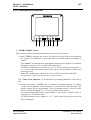
CAMÉRA TTV 1657D
TTV 1657D CAMERA
THOMSON
D
4
C
B
A 1
2
ON
S
OM
TH
PICT
F-
VTR
+ -
A
WBL B
PRST
F+
WHT
BLK
ON
SAVE
OFF
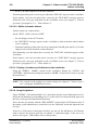
MANUEL D’UTILISATION
USER MANUAL
B1657D902C
Ce document et toute mise à jour et/ou complément d'information, ainsi que leurs copies, ne peuvent en aucun cas être reproduits, ni communiqués à une tierce partie, sans autorisation écrite de
THOMSON broadcast systems.
This document and any updates and/or supplemental information, including any copies thereof, can
not be reproduced, neither communicated to a third party, without written authorisation from
THOMSON broadcast systems.
© 2000
THOMSON
broadcast systems
All rights reserved.
PAGE BLANCHE
BLANK PAGE
3
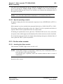
ATTENTION
La carte microprocesseur contient une pile LITHIUM. Il y a danger d'explosion en cas de
remplacement incorrect de la pile.
Remplacer uniquement par une pile de même type ou d'un type équivalent recommandé par le
constructeur.
WARNING
The Microprocesseur board is fitted with a LITHIUM battery. There is a danger of explosion should the battery be replaced by an incorrect type.
Only replace by a battery of identical type or an approved equivalent.
LITHIUM
BATTERY
+
MICROPROCESSOR UNIT
B1657D902C
THOMSON
4
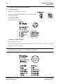
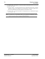
CODIFICATION DES CAMERAS/CAMERA CODIFICATIONS
PAL
B 1657D/E06 (.) : TTV1657D IT 4/3 750 Pts AVEC DEUX ROUES PORTE FILTRE MOTORISÉES
B 1657D/E06 (.) : TTV1657D IT 4/3 750 Pts WITH DUAL MOTORIZED FILTER WHEEL
B 1657D/M06 (.) : TTV1657D IT 4/3 750 Pts AVEC UNE ROUE PORTE FILTRE MANUEL
B 1657D/M06 (.) : TTV1657D IT 4/3 750 Pts WITH ONE MANUAL FILTER WHEEL
B 1657D/E12 (.) : TTV1657D IT 4/3 1000 Pts AVEC DEUX ROUES PORTE FILTRE MOTORISÉES
B 1657D/E12 (.) : TTV1657D IT 4/3 1000 Pts WITH DUAL MOTORIZED FILTER WHEEL
B 1657D/M12 (.) : TTV1657D IT 4/3 1000 Pts AVEC UNE ROUE PORTE FILTRE MANUEL
B 1657D/M12 (.) : TTV1657D IT 4/3 1000 Pts WITH ONE MANUAL FILTER WHEEL
B 1657D/E62 (.) : TTV1657D FIT 16/9 1000 Pts AVEC DEUX ROUES PORTE FILTRE MOTORISÉES
B 1657D/E62 (.) : TTV1657D FIT 16/9 1000 Pts WITH DUAL MOTORIZED FILTER WHEEL
B 1657D/M62 (.) : TTV1657D FIT 16/9 1000 Pts AVEC UNE ROUE PORTE FILTRE MANUEL
B 1657D/M62 (.) : TTV1657D FIT 16/9 1000 Pts WITH ONE MANUAL FILTER WHEEL
B 1657D/E64 (.) : TTV1657D FIT 16/9 1250 Pts AVEC DEUX ROUES PORTE FILTRE MOTORISÉES
B 1657D/E64 (.) : TTV1657D FIT 16/9 1250 Pts WITH DUAL MOTORIZED FILTER WHEEL
B 1657D/M64 (.) : TTV1657D FIT 16/9 1250 Pts AVEC UNE ROUE PORTE FILTRE MANUEL
B 1657D/M64 (.) : TTV1657D FIT 16/9 1250 Pts WITH ONE MANUAL FILTER WHEEL
NTSC
B 1657D/E07 (.) : TTV1657D IT 4/3 750 Pts AVEC DEUX ROUES PORTE FILTRE MOTORISÉES
B 1657D/E07 (.) : TTV1657D IT 4/3 750 Pts WITH DUAL MOTORIZED FILTER WHEEL
B 1657D/M07 (.) : TTV1657D IT 4/3 750 Pts AVEC UNE ROUE PORTE FILTRE MANUEL
B 1657D/M07 (.) : TTV1657D IT 4/3 750 Pts WITH ONE MANUAL FILTER WHEEL
B 1657D/E13 (.) : TTV1657D IT 16/9 1000 Pts AVEC DEUX ROUES PORTE FILTRE MOTORISÉES
B 1657D/E13 (.) : TTV1657D IT 16/9 1000 Pts WITH DUAL MOTORIZED FILTER WHEEL
B 1657D/M13 (.) : TTV1657D IT 16/9 1000 Pts AVEC UNE ROUE PORTE FILTRE MANUEL
B 1657D/M13 (.) : TTV1657D IT 16/9 1000 Pts WITH ONE MANUAL FILTER WHEEL
B 1657D/E63 (.) : TTV1657D FIT 16/9 AVEC DEUX ROUES PORTE FILTRE MOTORISÉES
B 1657D/E63 (.) : TTV1657D FIT 16/9 WITH DUAL MOTORIZED FILTER WHEEL
B 1657D/M63 (.) : TTV1657D FIT 16/9 AVEC UNE ROUE PORTE FILTRE MANUEL
B 1657D/M63 (.) : TTV1657D FIT 16/9 WITH ONE MANUAL FILTER WHEEL
(.) =Si une lettre est présente, la caméra est équipée de nouveaux filtres optiques (se
référer à la description de la caméra).
(.) =If a letter is present, the camera is fitted with news optical filters (refer to the camera
description)
THOMSON
B1657D902C
5
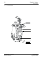
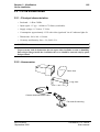
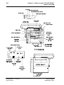
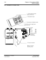
KIT DE MAINTENANCE/MAINTENANCE KIT
B1657D901 : Manuel de maintenance pour la TTV 1657D livré avec un prolongateur de carte,
un tournevis de réglage, une clé "allen".
B1657D901 : Maintenance manual for TTV 1657D supplied with one extender board, one
adjustment screwdriver, one allen wrench.
B1657D902C
THOMSON
6
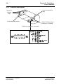
THOMSON
VIEWFINDER
Clef Allen
Allen wrench
carte allonge pour 1657D
extender board for 1657D
viseur 14 cm
viewfinder 14 cm
E
C
N
A
N
E
T
Service manual
I
A
M
N
DIGITAL
ENCODER OPTION
Manuel de maintenance
Spectrol screwdriver
CCU 1685
TRIAX
CA 85
MAINTENANCE KIT
DIGITAL
CCU 1686
ENCODER OPTION
MICROCAM OPTION
OCP40/42
APCM OPTION
MICROPHONE HOLDER
CCU 1625
MULTICORS
CA 25
B1657714
COURROIE/CARRYING STRAP
TTV 3535
TTV 4005
TTV 3425
OCP40/42
HOUSSE/RAIN COVER
B1657D902C
E
S
U
NP1.B
TTV 3505
MANUEL D'EXPLOITATION SUPPLEMENTAIRE
EXTRA
OPERATIONAL MANUAL
VALISE/CASE
AL 500
BC1 WB
DC 510
DC 500
CONFIGURATION/CONFIGURATION
KIT DE MAINTENANCE
MICROPHONE
7
PAGE BLANCHE
BLANK PAGE
B1657D902C
THOMSON
8
THOMSON
B1657D902C
9
SOMMAIRE / CONTENTS
SECTION 1 - VERSION FRANÇAISE
CHAPITRE 1
PRINCIPALES CARACTÉRISTIQUES ............................................ 15
CHAPITRE 2
CAMÉRA ........................................................................................... 19
CHAPITRE 3
VISEURS ........................................................................................... 61
CHAPITRE 4
OBJECTIF ......................................................................................... 75
CHAPITRE 5
MAGNÉTOSCOPE TTV 3505 (BVV5) .............................................. 81
CHAPITRE 6
ADAPTATEUR ARRIÈRE (CA25) .................................................... 95
B1657D902C
THOMSON
10
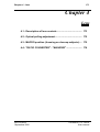
SECTION 2 - ENGLISH VERSION
CHAPTER 1
MAIN CHARACTERISTICS ............................................................ 111
CHAPTER 2
CAMERA ......................................................................................... 115
CHAPTER 3
VIEWFINDERS ................................................................................ 157
CHAPTER 4
LENS ............................................................................................... 171
CHAPTER 5
VIDEO RECORDER TTV 3505 (BVV5) ........................................... 177
CHAPTER 6
REAR ADAPTER (CA25) ................................................................ 191
THOMSON
B1657D902C
SECTION 1 - Version Française
11
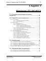
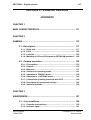
SECTION 1 - VERSION FRANÇAISE
SOMMAIRE
CHAPITRE 1
PRINCIPALES CARACTÉRISTIQUES ............................................. 15
CHAPITRE 2
CAMÉRA............................................................................................ 19
2.1 - Description .................................................................... 21
2.1.1 - Côté droit..................................................................................
2.1.2 - Face avant ................................................................................
2.1.3 - Côté gauche .............................................................................
2.1.4 - Adaptation des signaux CR et CB au standard BETACAM .
21
24
29
33
2.2 - Exploitation.................................................................... 36
2.2.1 - Présentation.............................................................................
2.2.2 - Généralités ...............................................................................
2.2.3 - Les Balances............................................................................
2.2.4 - Sélection du mode d'exploitation ..........................................
2.2.5 - Exploitation en mode "BASIC"...............................................
2.2.6 - Exploitation en mode "CUSTOM" ..........................................
2.2.7 - Fonctions d'exploitation cadreur avec un OCP....................
2.2.8 - Signification des réglages d’exploitation..............................
2.2.9 - Signification des status ..........................................................
36
37
41
45
46
47
48
49
59
CHAPITRE 3
VISEURS............................................................................................ 61
3.1 - Viseur 4 cm .................................................................... 63
3.1.1 - Commandes et fonctions........................................................ 63
3.1.2 - Signalisations lumineuses ..................................................... 65
B1657D902C
Septembre 2000
THOMSON TTV 1657D
Manuel utilisateur
12
SECTION 1 - Version Française
3.1.3 - Réglages électriques .............................................................. 66
3.1.4 - Réglages mécaniques ............................................................ 67
3.2 - Viseur 14 cm .................................................................. 69
3.2.1 - Principales caractéristiques ..................................................
3.2.2 - Accessoires .............................................................................
3.2.3 - Description générale...............................................................
3.2.4 - Description des commandes .................................................
3.2.5 - Montage du viseur sur son support ......................................
69
70
70
71
73
CHAPITRE 4
OBJECTIF .......................................................................................... 75
4.1 - Description des commandes........................................ 77
4.2 - Réglage du tirage optique ............................................ 79
4.3 - Position macro (mise au point sur des objets rapprochés)
79
4.4 - "RATIO CONVERTER" - "MANIFIER" .......................... 80
CHAPITRE 5
MAGNÉTOSCOPE TTV 3505 (BVV5) ............................................... 81
5.1 - Principales caractéristiques du lecteurenregistreur............................................................................ 83
5.2 - Préparatifs avant enregistrement ................................ 85
5.2.1 - Sur la caméra........................................................................... 85
5.2.2 - Sur le viseur............................................................................. 85
5.2.3 - Sur le magnétoscope.............................................................. 87
5.3 - Enregistrement .............................................................. 92
5.3.1 - Commande de début et de fin d’enregistrement.................. 92
5.3.2 - Vérification du signal luminance pendant l’enregistrement 92
THOMSON TTV 1657D
Manuel utilisateur
B1657D902C
Septembre 2000
SECTION 1 - Version Française
13
5.3.3 - Vérification du signal chrominance pendant l’enregistrement
92
5.3.4 - Vérification du temps codé (TIME CODE), du Bit Utilisateur (UBIT), du temps réel (REAL TIME) et du compteur trames (CTL) .... 92
5.4 - Vérifications après enregistrement ............................. 93
5.4.1 - Vérification de la dernière scène enregistrée ....................... 93
5.4.2 - Montage de précision par espacement arrière ..................... 93
CHAPITRE 6
ADAPTATEUR ARRIÈRE (CA25) ..................................................... 95
6.1 - Connections .................................................................. 97
6.2 - Description de l’adaptateur .......................................... 98
6.3 - Définitions des connecteurs ...................................... 100
6.4 - Description des commandes ..................................... 104
6.4.1 - Commandes externes ........................................................... 104
6.4.2 - Commandes externes ........................................................... 105
6.5 - Signalisations .............................................................. 105
6.6 - Accessoires ................................................................. 105
6.7 - Fonctions des commutateurs internes à la carte MASTER
BOARD ................................................................................. 106
B1657D902C
Septembre 2000
THOMSON TTV 1657D
Manuel utilisateur
14
THOMSON TTV 1657D
Manuel utilisateur
SECTION 1 - Version Française
B1657D902C
Septembre 2000
Chapitre 1 - Principales caractéristiques
15
Chapitre 1
Principales caractéristiques
B1657D902C
Septembre 2000
THOMSON TTV 1657D
Manuel utilisateur
16
THOMSON TTV 1657D
Manuel utilisateur
Chapitre 1 - Principales caractéristiques
B1657D902C
Septembre 2000
Chapitre 1 - Principales caractéristiques
17
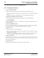
Standards :
• 625/50 PAL, Composantes,
• 525/60 NTSC, Composantes.
Capteurs :
• IT 4/3 750 Pts ou IT 16/9 - 4/3 1000 Pts,
• FIT 16/9 - 4/3 1000 Pts ou FIT 16/9 - 4/3 1250 Pts,
Système optique :
Séparateur à prisme, f/1.4, RGB, température de couleur électronique équipé avec :
1ère Version :
• une roue avec 4 filtres de densité à commande manuelle (1=Clear, 2=1/2, 3=1/4,
4=1/16),
ou
• deux roues motorisées: une avec 4 filtres de densité (1=Clear, 2=1/2, 3=1/4, 4=1/16),
une avec 4 filtres d'effet (A=Clear, B=Star 4, C=Centre net,
D=Brouillard).
2ème Version :
• une roue avec 4 filtres de densité à commande manuelle (1=Clear, 2=1/4, 3=1/16,
4=1/64),
ou
• deux roues motorisées: une avec 4 filtres de densité (1=Clear, 2=1/4, 3=1/16, 4=1/64),
une avec 4 filtres d'effet (A=Clear, B=Star 4 , C=Brouillard fort,
D=Brouillard faible).
Montage de l’optique :
Monture baïonnette standard.
Traitement vidéo :
Numérique 12 bits.
Rapport Signal/bruit :
Objectif fermé, Niveau du noir = 70 mV, Filtres PH 100 kHz et PB 5 MHz, γ =1,0 dB,
Contour OFF, Masking OFF S/B eff sur la luminance ≥ 60 dB.
Sensibilité :
• Conditions de test : 0 dB, Blanc 90 % de réflectance, 3200 °K, ouverture d’objectif = f/8,
• CCDs type FIT ou IT : 1600 Lux.
Taux de modulation à 400 lignes TV (5,1 MHz en 4/3 ou 6,8 MHz en 16/9) :
En luminance : > 55 % (Contour OFF) et 100 % après correction (Contour ON).
B1657D902C
Septembre 2000
THOMSON TTV 1657D
Manuel utilisateur
18
Chapitre 1 - Principales caractéristiques
Superpositions (*) :
Zone 1 : 20 ns - Zone 2 : 30 ns - Zone 3 : 40 ns.
Consommation :
• IT 4/3 avec viseur 1,5" : 18 W, sans viseur: 16,5 W,
• FIT 4/3 avec viseur 1,5" : 20 W, sans viseur: 18,5 W,
• FIT 16/9 4/3 avec viseur 1,5" : 21 W, sans viseur: 19,5 W.
Poids :
3,5 kg environ avec viseur.
Environnement :
• en fonctionnement : - 20 °C à + 45 °C - humidité relative 95 % sans condensation,
• en stockage : - 20 °C à + 55 °C - humidité relative 95 % sans condensation.
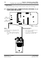
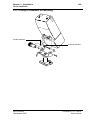
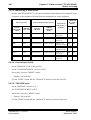
Dimensions :
Largeur : 123 mm.
230
320
230
191
276
(*)
fonction de l’objectif utilisé.
THOMSON TTV 1657D
Manuel utilisateur
B1657D902C
Septembre 2000
Chapitre 2 - Caméra
19
Chapitre 2
Caméra
2.1 - Description .................................................................... 21
2.1.1 - Côté droit .............................................................................................
2.1.2 - Face avant ...........................................................................................
2.1.3 - Côté gauche ........................................................................................
2.1.4 - Adaptation des signaux CR et CB au standard BETACAM.................
21
24
29
33
2.2 - Exploitation.................................................................... 36
2.2.1 - Présentation......................................................................................... 36
2.2.1.1 - Visualisations ................................................................................... 36
2.2.1.2 - Diagnostics ...................................................................................... 36
2.2.2 - Généralités .......................................................................................... 37
2.2.2.1 - Affichage des status......................................................................... 37
2.2.2.2 - Modification d'un réglage d'exploitation ........................................... 38
2.2.2.2.1 - Cas général ..................................................................... 38
2.2.2.2.2 - Cas particuliers ................................................................ 39
2.2.2.3 - Messages permanents dans le viseur ............................................. 40
2.2.2.4 - Temps d’affichage............................................................................ 40
2.2.3 - Les Balances ....................................................................................... 41
2.2.3.1 - Balance des noirs ............................................................................ 41
2.2.3.2 - Balance des blancs.......................................................................... 42
2.2.3.2.1 - Preset et mémoires de balance ....................................... 42
2.2.3.2.2 - Balance automatique déclenchée.................................... 43
2.2.3.2.3 - Balance automatique permanente................................... 44
2.2.4 - Sélection du mode d'exploitation ......................................................... 45
2.2.4.1 - Mode "BASIC".................................................................................. 45
2.2.4.2 - Mode "CUSTOM"............................................................................. 45
2.2.5 - Exploitation en mode "BASIC".............................................................
2.2.6 - Exploitation en mode "CUSTOM" ........................................................
2.2.7 - Fonctions d'exploitation cadreur avec un OCP....................................
2.2.8 - Signification des réglages d’exploitation..............................................
46
47
48
49
2.2.8.1 - Fonctions principales .......................................................................
2.2.8.2 - Fonctions MARKERS.......................................................................
2.2.8.3 - Exploitation et fonctions du SKIN.....................................................
2.2.8.4 - Fonctions CUSTOM FILE ................................................................
49
53
55
57
2.2.9 - Signification des status ........................................................................ 59
B1657D902C
Septembre 2000
THOMSON TTV 1657D
Manuel utilisateur
20
THOMSON TTV 1657D
Manuel utilisateur
Chapitre 2 - Caméra
B1657D902C
Septembre 2000
Chapitre 2 - Caméra
Description
21
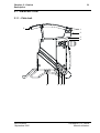
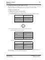
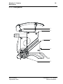
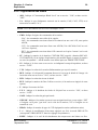
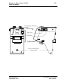
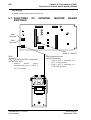
2.1 - DESCRIPTION
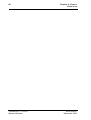
2.1.1 - Côté droit
9
1
2
3
4
RE
MO
TE
GE
NL
OC
K
VID
EO
8
B1657D902C
Septembre 2000
7
6
OU
T
5
THOMSON TTV 1657D
Manuel utilisateur
22
Chapitre 2 - Caméra
Description
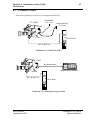
1 - Fixation d’accessoires (micro, lampe, ...)
2 - Embase "MIC"
Entrée d’un microphone (- 60 dB).
XL RNCF 30-V
Une tension d'alimentation fantôme de 12 Vdc est délivrée sur cette prise.
3
3
2
1
2
1
3 - Embase "LENS"
Raccordement de l'objectif.
Embase
HR-10-10R-12S
Réf : 91.553.055
12
7
Prise correspondante
HR-10-10P-12P
Réf : 91.582.124
1 : Lens vidéo ext SW
2 : Lens start/stop.
3 : -BATT.
4 : 5v Auto Lens.
5 : Iris Ctrl.
6 : +BATT.
1
9
8
10
2
11
3
6
4
5
7 : Iris position.
8 : Iris Remote/Local.
9 : Extender On/Off.
10 : Zoom position .
11 : Focus position .
12 : On Air lens.
4 - Embase "VIEWFINDER"
Raccordement du viseur.
La vidéo disponible sur cette embase peut être: Y, R, G, B, (R-G), (B-G) ou la vidéo
externe (Niveau 1 Vcc/75 Ω).
NOTA :Les vidéos R, G, B ne sont pas disponibles si la mire de barres est sélectionnée et
sont remplacées par la vidéo Y. Se reporter à l'exploitation.
Embase femelle
DJ-211N-605 SPE.
Réf. 96.103.316
Prise correspondante
EJ-212J-610.
Réf. 96.103.314
1 : Vidéo OUT
2 : Vidéo GND
3 : +9,1v
4 : GND
5 : Ind +12v BATT
6 : Shield GND
7 : Audio cont VTR
8 : Not connected
9 : MISO
10 : MOSI
THOMSON TTV 1657D
Manuel utilisateur
2
1
6
5
4
12 11
10
9
8
17 16
15
14
13
20
19
18
7
3
11 : SCK
12 : Tally Rec
13 : SS0
14 : SS1
15 : Not connected
16 : Not connected
17 : Vidéo 2 OUT
18 : Vidéo 2 GND
19 : Vidéo 3 OUT
20 : Vidéo 3 GND
B1657D902C
Septembre 2000
Chapitre 2 - Caméra
Description
23
5 - Embase "VIDEO OUTPUT"
La vidéo disponible sur cette embase peut être: R, G, B, (R-G), (B-G) ou ENC (Niveau
1 Vcc/75 Ω).
Se reporter à l'exploitation.
6 - Embase "GEN-LOCK"
Entrée du signal vidéo GEN-LOCK pour asservir le générateur de synchronisation (H, V,
SP) de la caméra par une source vidéo codée extérieure.
7 - Embase "REMOTE IN"
Raccordement d'un pupitre OCP 40/42.
Pour l’exploitation de la caméra à partir d'un pupitre, se reporter à la notice du pupitre.
Embase
HR-10-10R-10S
Prise correspondante
HR-10-10P-10P
1 : +12v BATT.
2 : RB+.
3 : RA-.
4 : EXT OCP RDY.
5 : -BATT.
6 : AB+.
8
7
10
1
2
9
6
3
5
4
7 : AA-.
8 : Not Connected
9 : +12V BATT.
10 : -BATT.
8 - Poussoir
Déverrouillage de l’épaulière coulissante.
9 - Voyants de signalisation
La caméra connectée sur un magnétoscope, ces voyants indiquent que l'enregistrement est
en cours.
La caméra connectée sur un CCU (contrôle de voie), ces voyants indiquent que la caméra
est à l'antenne (ON AIR) ou un appel de l'opérateur du pupitre (CALL).
B1657D902C
Septembre 2000
THOMSON TTV 1657D
Manuel utilisateur
24
Chapitre 2 - Caméra
Description
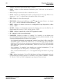
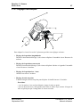
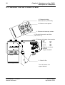
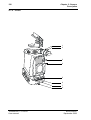
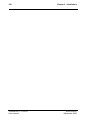
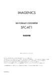
2.1.2 - Face avant
1
2
3
4
+-
WHT
BLK
5
VTR
6
7
8
THOMSON TTV 1657D
Manuel utilisateur
B1657D902C
Septembre 2000
Chapitre 2 - Caméra
Description
25
1 - Bague de serrage de la colonne support de viseur
Pour désolidariser la colonne du corps de la caméra, desserrer cette bague et tirer la
colonne en la faisant pivoter d'un quart de tour vers la gauche (sens de la flèche).
2 - Bague de serrage du viseur
3 - Commande de la ou des roues porte-filtres
• Si la caméra est équipée d'une roue porte filtres:
La commande manuelle permet de mettre en place l'un des filtres optiques suivant:
Se référer au NOTA
1: Clear
1: Clear
2: 1/2 (T = 50 %)
2: 1/4 (T = 25 %)
3: 1/4 (T = 25 %)
3: 1/16 (T = 6,3 %)
4: 1/16 (T = 6,3 %)
4: 1/64 (T = 1,6 %)
4
1
3
2
• Si la caméra est équipée de deux roues porte filtres motorisées:
-une roue équipée de filtres de densité :
Se référer au NOTA
1: Clear
1: Clear
2: 1/2 (T = 50 %)
2: 1/4 (T = 25 %)
3: 1/4 (T = 25 %)
3: 1/16 (T = 6,3 %)
4: 1/16 (T = 6,3 %)
4: 1/64 (T = 1,6 %)
-une roue équipée de filtres d'effet :
Se référer au NOTA
A: Clear
A: Clear
B: Star 4
B: Star 4
C: Centre net
C: Brouillard fort
D: Brouillard
D: Brouillard faible
Les roues porte filtres sont actionnables par menu. Néanmoins la rotation manuelle est
toujours possible, et est alors assistée électriquement.
B1657D902C
Septembre 2000
THOMSON TTV 1657D
Manuel utilisateur
26
Chapitre 2 - Caméra
Description
NOTA : Ces filtres équipent les caméras dont la référence se termine par une lettre.
Exemple B1657DE06X
La référence est indiquée sur la poignée de la caméra.
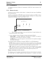
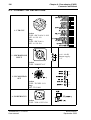
Il existe 2 versions de commande des roue porte filtres, en fonction de la disposition des
roues d'effet et de densité dans le bloc optique.
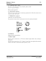
1ère VERSION :
Roue de densité
D
4
C
3
A
1
B
2
Roue d'effet
FILTRE PASSE BAS
CCD
BLEU
ROUE FILTRES
D'EFFET
(A à D)
FILTRE
CCD
VERT
GLACE
DE PROTECTION
ROUE FILTRES
DE DENSITÉ
FILTRE
CCD
(1 à 4)
INFRAROUGE
ROUGE
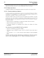
2ème VERSION :
D
Roue d'effet
4
1
3
A
C
2
B
Roue de densité
FILTRE PASSE BAS
CCD
BLEU
ROUE FILTRES
DE DENSITÉ
(1 à 4)
FILTRE
CCD
VERT
GLACE
DE PROTECTION
ROUE FILTRES
THOMSON TTV 1657D
Manuel utilisateur
D'EFFET
FILTRE
CCD
(A à D)
INFRAROUGE
ROUGE
B1657D902C
Septembre 2000
Chapitre 2 - Caméra
Description
27
4 - Bague de fixation de l’objectif
5 - Sélecteur "WHT BLK"
Sélecteur trois positions à retour automatique en position centrale :
• le basculement du sélecteur vers WHT déclenche le réglage automatique de la balance
des blancs,
• le basculement du sélecteur vers BLK déclenche les réglages automatiques des
contretops et de la balance des noirs. Un appui prolongé (supérieur à 3 sec.) vers BLK
déclenche le cycle de réglage automatique des tâches aux noirs.
Balance automatique des blancs (ou équilibrage au blanc des niveaux RVB) :
• Rôle : cet automatisme permet de compenser les erreurs de niveau vidéo RVB dues aux
changements des conditions d’éclairage de la scène.
• Observations :
1) L’automatisme de balance des blancs égalise les niveaux RVB de l’objet le plus
lumineux situé dans la zone centrale de l’image. En conséquence, veillez aux points
suivants :
- placer la référence de blanc au centre de l’image,
- s’assurer qu’aucun autre objet lumineux ne se trouve dans cette zone centrale.
2) Sélectionner la mémoire A ou B de la balance des blancs.
3) Effectuer une balance des blancs avant chaque prise de vues et à chaque changement de température de couleur de l’éclairage.
Les corrections sont conservées lorsque l’équipement est mis hors tension.
• NOTAS :
1) La caméra possède un mode "balance des blancs permanente" dans lequel la
balance s'effectue en permanence. Pour activer ce mode, actionner une seconde fois
le sélecteur vers "WHT" avant la fin du cycle de balance automatique ("W" s'affiche
dans le viseur). Pour quitter ce mode actionner une nouvelle fois le sélecteur vers
"WHT".
2) En "ENG", la caméra est forcée en mode iris auto durant le temps de la balance
(sauf en mode balance permanente).
Balance automatique des noirs (ou équilibrage au noir des niveaux RVB) :
• Rôle : cet automatisme égalise les niveaux des noirs RVB et règle les contretops pour
maintenir le noir à un niveau constant quel que soit le gain de la caméra.
• Observations :
1) Effectuer une balance automatique des noirs à la première prise de vue de la
journée.
B1657D902C
Septembre 2000
THOMSON TTV 1657D
Manuel utilisateur
28
Chapitre 2 - Caméra
Description
2) L'automatisme ferme l'iris pendant le temps du réglage. En conséquence, si l’inverseur d’iris placé sur l’objectif était sur la position MAN, l’objectif reste fermé à la
fin du réglage.
6 - Touche " +
-"
Le rôle de ces touches est défini dans la partie EXPLOITATION.
7 - Bouton poussoir "VTR"
Cette commande est montée en parallèle avec le bouton «VTR» de l’objectif.
• Si un magnétoscope est connecté sur la caméra : presser ce bouton pour commander
le début de l’enregistrement. Une autre action sur ce bouton commande la fin de
l’enregistrement.
• En mode EFP TRIAXIAL : permet au Cadreur d'activer momentanément la liaison
audio CAM vers PROD si le commutateur "ENG REMOTE PROD" situé à l'arrière du
CA85 est en position "REMOTE".
• En mode EFP MULTICONDUCTEURS : ce bouton permet au Cadreur d'appeler le
Réalisateur ou le Technicien d’exploitation.
8 - Griffe de fixation de la caméra sur sa semelle
Cette griffe possède des trous permettant de fixer un "Matte Box".
THOMSON TTV 1657D
Manuel utilisateur
B1657D902C
Septembre 2000
Chapitre 2 - Caméra
Description
29
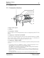
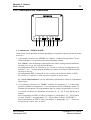
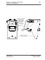
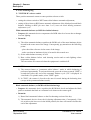
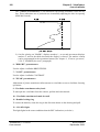
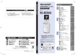
2.1.3 - Côté gauche
1
2
3
4
5
B1657D902C
Septembre 2000
THOMSON TTV 1657D
Manuel utilisateur
30
Chapitre 2 - Caméra
Description
1 - Doigt d’attache
Fixation de la courroie de portage.
2 - Queue d’arronde femelle
Fixation pour l'adaptateur arrière ou le magnétoscope connecté sur la caméra.
3 - Embase 50 Pts
Liaison entre l'adaptateur arrière ou le magnétoscope et la caméra.
D02-50P-T
1
2
3
4
5
6
7
8
9
10 11 12 13 14
15 16 17
18 19 20 21 22 23 24 25 26 27 28 29 30 31 32 33
34 35 36 37 38 39 40 41 42 43 44 45 46 47 48 49 50
1 - VIDEO GEN LOCK IN
VIDEO GEN LOCK IN*
2 - GEN LOCK GND
3 - +9V CAM OUT
4 - -5V CAM OUT
5 - POWER GND
6 - POWER GND
7 - RED VIDEO OUT
8 - GREEN VIDEO OUT
9 - BLUE VIDEO OUT
10 - R G B GND
11 - N C
12 - N C
13 - N C
14 - SCD IN, OUT
SD CAM CA OUT *
SD CAM CA OUT**
15 - MIC CAM GND
16 - MIC CAM X OUT
17 - MIC CAM Y OUT
18 - VIDEO EXT IN
19 - VIDEO EXT GND
20 - AUDIO LEVEL IND IN
NOT USED *
NOT USED **
21 - SPARE
22 - TAPE IND 10MN IN
SD CA CAM IN *
SD CA CAM IN **
23 - TAPE IND 5 MN IN
NOT USED *
ASS H IN **
24 -REC TALLY IN
REC TALLY IN *
MISO CA IN **
25 - BATT IND IN
CCU IND -5v IN *
CA INFO -9v IN **
26 - CTRL VIDEO EXT IN
CTRL VIDEO EXT IN *
MOSI CA OUT **
27 - VTR START/STOP
CALL IN *
SS CA 0 OUT **
28 - NOT USED
29 - R-Y VIDEO OUT
NOT USED **
30 - GND R-Y
31 - AUDIO CONT CH1 OUT
NOT USED *
NOT USED **
32 - VTR SAVE OUT
33 - AUDIO MONITOR IN
34 - SYNC OUT
35 - NOT USED
36 - PB STATUS IN
NOT USED *
SCK CA OUT**
37 - COLOUR FRAME OUT
38 - CTRL VIDEO EXT OUT
CTRL VIDEO EXT OUT*
RAZ V IN **
39 - POWER IN
40 - POWER IN
41 - Y VIDEO OUT
42 - GND Y
43 - ENCODED VIDEO OUT
44 - ENCODED VIDEO GND
45 - SPARE
PHANTOM POWER IN **
46 - NOT USED
47 - NOT USED
48 - RESERVED
49 - B-Y VIDEO OUT
NOT USED **
50 - GND B-Y
* With CCU 1625 ** With CA 85
4 - Système de fixation
Fixation mécanique de l'adaptateur arrière ou du VTR.
THOMSON TTV 1657D
Manuel utilisateur
B1657D902C
Septembre 2000
Chapitre 2 - Caméra
Description
31
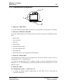
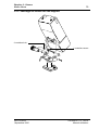
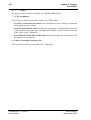
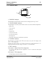
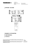
5 - Commandes d’exploitation gauches
1
2
PICT
A
WBL
F+
GAIN
F+
ON
B
PRST
3
4
5
SAVE
1 - "F+" "F-" : Inverseur à 3 positions à retour automatique en position centrale.
Le rôle de cet inverseur est défini dans la partie EXPLOITATION.
2 - "PICT" : Inverseur à 3 positions à retour automatique en position centrale permettant de sélectionner la vidéo de sortie de la caméra :
• un appui vers "PICT" impose la vidéo image,
• un premier appui vers l'opposé de "PICT" impose la mire de barres,
• un deuxième appui vers l'opposé de "PICT" impose le signal test "SAW".
Cet inverseur est inactif si la caméra est exploitée à partir d'un pupitre.
3 - "WBL" : Inverseur à 3 positions stables permettant de sélectionner la mémoire de
balance des blancs :
• si l'inverseur est en position "A" les valeurs de corrections de température de couleur
apportées sur les vidéos suite au déclenchement d'une balance des blancs seront
mémorisées dans la mémoire A,
• si l'inverseur est en position "B" les valeurs de corrections apportées seront
mémorisées dans la mémoire B.
Pour rappeler les valeurs mémorisées il suffit de placer l'inverseur sur "A" ou "B",
• si l'inverseur est en position "PRESET" la balance des blancs n'apporte aucune
correction de température de couleur sur les vidéos.
NOTA : Il existe deux références de "PRESET": 3100°K et 5600°K (Se référer à la
partie EXPLOITATION).
Cet inverseur est inactif si la caméra est exploitée à partir d'un pupitre.
4 - "GAIN" : Inverseur à 3 positions à retour automatique en position centrale permettant de sélectionner le gain général de la caméra (Se référer à la partie EXPLOITATION).
Cet inverseur est inactif si la caméra est exploitée à partir d'un pupitre.
B1657D902C
Septembre 2000
THOMSON TTV 1657D
Manuel utilisateur
32
Chapitre 2 - Caméra
Description
5 - "SAVE - ON" : Interrupteur à 2 positions stables commandant la mise en service de
la caméra et du VTR :
1) Position "SAVE" : la caméra fonctionne mais le début d'enregistrement est différé
pendant le temps du verrouillage des servomécanismes et de mise en phase nécessaire au raccordement correct des séquences (concernant le VTR).
2) Position "ON" : la caméra fonctionne et l'enregistrement sera immédiat dés l'appui
sur la touche VTR.
NOTA : La position de cet interrupteur influe sur les fonctions d’exploitation s'affichant
dans le viseur (Se référer à la partie EXPLOITATION).
THOMSON TTV 1657D
Manuel utilisateur
B1657D902C
Septembre 2000
Chapitre 2 - Caméra
Description
33
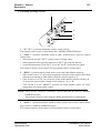
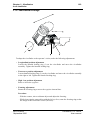
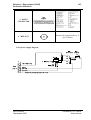
2.1.4 - Adaptation des signaux CR et CB au standard BETACAM
Norme UER (N10) : l'amplitude crête à crête des signaux CR et CB est de 0,7 V/75 Ω pour
une mire de bars 100/0/100/0 (soit 0,525 V pour une mire de bars 100/0/75/0).
Les caméras sont normalement livrées conforme à la norme UER.
Norme BETA : l'amplitude crête à crête des signaux CR et CB est de 0,7 V/75 Ω pour une
mire de barres 100/0/75/0 (soit 0,933 V pour une mire de barres 100/0/100/0).
L'adaptation suivante ne doit être effectuée que par un personnel qualifié.
Pour adapter les signaux CR et CB au standard BETACAM :
• dévisser les 4 vis de fixation de la porte gauche de la caméra,
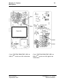
• extraire la carte "DIGITAL PROCESS".
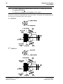
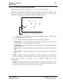
NOTA :Deux versions de carte DP peuvent équiper la caméra. Les 2ème versions de carte
sont équipées d'une carte fille.
- Carte 1ère version (sans carte fille)
Sur la carte "DP" (DIGITAL PROCESS) dessouder les résistances (0 Ω) suivantes :
- R748, R752 pour CR
- R788, R792 pour CB
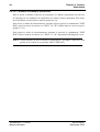
- Cartes 2ème version (avec carte fille)
Sur les cartes "DP1" ou "DP2" (DIGITAL PROCESS) dessouder les résistances (0 Ω)
suivantes :
- R255, R261 pour CR
- R328, R331 pour CB
B1657D902C
Septembre 2000
THOMSON TTV 1657D
Manuel utilisateur
34
Chapitre 2 - Caméra
Description
R752
R748
R792
R788
Carte "DIGITAL PROCESS" 1ère version (sans carte fille) vue côté opposé aux
connecteurs.
THOMSON TTV 1657D
Manuel utilisateur
B1657D902C
Septembre 2000
Chapitre 2 - Caméra
Description
35
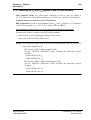
R331
R261
Carte fille
R255
R328
Carte "DIGITAL PROCESS" (DP1 ou
DP2) 2ème version vue côté connecteurs
B1657D902C
Septembre 2000
Carte "DIGITAL PROCESS" (DP1 ou
DP2) 2ème version vue côté opposé aux
connecteurs
THOMSON TTV 1657D
Manuel utilisateur
36
Chapitre 2 - Caméra
Exploitation
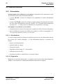
2.2 - EXPLOITATION
2.2.1 - Présentation
Si aucun pupitre n'est en liaison avec la caméra, l'exploitation de la caméra peut se faire
suivant deux modes de fonctionnement différents :
• le mode "BASIC" permet de configurer très rapidement la caméra (Exploitation
Standard),
• le mode "CUSTOM" permet de configurer certains réglages d'exploitation particuliers
liés à des choix d'exploitations autres que "BASIC". Ex : Niveau de détail, température
de couleur etc.... Ce mode permet à l'exploitant de "personnaliser" son image.
Si un pupitre est en liaison avec la caméra :
• l'exploitation de la caméra se fait à partir de ce pupitre (Se référer à la notice du pupitre),
• pour les différentes fonctions accessibles par le cadreur, se référer au paragraphe 2.2.7
-"Fonctions d'exploitation cadreur avec un OCP".
2.2.1.1 - Visualisations
Le viseur fournira en plus de l'image de contrôle de prise de vue, des informations directes
par voyants (Ex : batterie déchargée....), et des informations appelées et incrustées sur
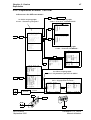
l'écran :
• status ou état d'exploitation,
• graticule d'aide au cadrage,
• messages d’alarme,
• bargraphes en/hors image. Ex : niveau audio,
• indication du niveau vidéo,
• fonctions accessibles en mode Basic ou en mode Custom.
2.2.1.2 - Diagnostics
Diagnostics de première maintenance : ce contrôle, après test des unités interchangeables,
indique le sous-ensemble éventuellement défaillant et devant être remplacé.
THOMSON TTV 1657D
Manuel utilisateur
B1657D902C
Septembre 2000
Chapitre 2 - Caméra
Exploitation
37
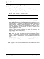
2.2.2 - Généralités
La caméra s'exploite principalement à l'aide d'affichages superposés à l'image dans le
viseur. Sur la caméra les commandes de gain (4), de mire de barres (2), de signaux test (2)
et de balances (3) (6) sont à accès direct.
A la demande de l'exploitant (commande "F+, F-") (1), des menus signifiés "FUNCTIONS" proposant différents réglages d'exploitation s'inscrivent dans le viseur.
Le contenu de ces menus dépend :
1. Du mode d'exploitation choisi ("BASIC" ou "CUSTOM").
2. De la position de l'interrupteur "SAVE-ON" (5). La position "SAVE" est utilisée
pour la préparation de la caméra et la position "ON" pour l'exploitation de la caméra.
A la demande de l'exploitant des affichages de "STATUS" peuvent également s'inscrire
dans le viseur. Ces affichages renseignent sur la configuration de la caméra, se référer au
paragraphe 2.2.9 -"Signification des status".
2.2.2.1 - Affichage des status
Pour avoir l'affichage des status appuyer sur l'interrupteur "PICT" (2) si la caméra est déjà
en image. L'extinction de l'affichage se fera après une durée de quelques secondes définie
en maintenance.
1
2
PICT
A
WBL
F-
B
PRST
3
+
GAIN
F+
4
5
ON
SAVE
+-
VTR
WHT
BLK
6
7
B1657D902C
Septembre 2000
THOMSON TTV 1657D
Manuel utilisateur
38
Chapitre 2 - Caméra
Exploitation
2.2.2.2 - Modification d'un réglage d'exploitation
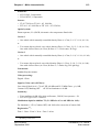
2.2.2.2.1 - Cas général
Pour modifier un réglage
La caméra étant en position "SAVE" ou "ON" (5) :
• appuyer sur l'interrupteur "F+" ou "F-" (1), le menu "FUNCTIONS" du mode
d'exploitation choisi s'affiche,
• par appuis successifs sur ce même interrupteur "F+" ou "F-" (1), sélectionner le réglage
à modifier en déplaçant le curseur →,
• par appuis sur les touches "+" ou "-" (7) en face avant, effectuer le réglage. L'appui
simultané sur les touches "+" et "-" permet d'augmenter la vitesse de défilement, le sens
étant déterminé par la première touche appuyée.
NOTA : Seul sept réglages peuvent s'afficher simultanément, les autres étant obtenus par
"scrolling" en déplaçant le curseur → vers le haut ou vers le bas.
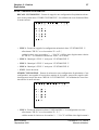
EXEMPLE : La caméra est en mode "CUSTOM" et l'exploitant veut mettre la fonction
"CLEAR SCAN" en service :
• placer l' interrupteur "SAVE ON" (5) en position "ON",
• actionner le commutateur (1) vers "F+" ou "F-" pour faire apparaître le menu de
fonctions suivant :
Indication du mode d’exploitation
Indication de la position
de l’interrupteur (5)
Curseur
THOMSON TTV 1657D
Manuel utilisateur
CUSTOM FUNCTI ONS
--- - -- -ON- -CFX. * -- - >SHUTTER : - - SHUTTER SPEED : - - - CLEAR SCAN : - - CL SC SPEED : - - - KNEE : - - - ABL : - - DFZ : - --
DFZ WIDEorTELE : - - IRISOFFSET : - - COLOR TEMP (K) : - - - EFFECT FILTER : - - - NEUTRAL FILTER : - - --
MASTERPED : - - DETAIL LEVEL : - - SKIN DETAIL : - - SKIN DTL LVL : - - SKIN VIEW : - - SKIN ACQUIS. : - --
Voir NOTA
B1657D902C
Septembre 2000
Chapitre 2 - Caméra
Exploitation
39
• par appuis successifs du commutateur (1) vers "F+" ou "F-", positionner le curseur
devant "CLEAR SCAN",
• par appuis sur les touches "+" ou "-" (7) effectuer le réglage.
NOTA : CF indique le numéro de la dernière "CUSTOM FILE" rappelée (fonction
"RECALL CUSTOM FILE" disponible si l'interrupteur (1) est en position
"SAVE"). Si un réglage d'exploitation a été modifié depuis ce rappel, le numéro
est suivi du symbole * .
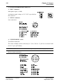
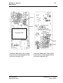
2.2.2.2.2 - Cas particuliers
Commandes situées côté gauche de la caméra
• GAIN (4) : permet de faire varier directement le gain général par bonds de 6 dB (sauf
pour la valeur 18-21 dB) ; les valeurs accessibles directement sont donc 0 dB, 6 dB,
12 dB, 18 dB, 21 dB.
Les valeurs intermédiaires - 3 dB, 3 dB, 9 dB, 15 dB, sont obtenues par appuis sur les
touches "+" ou "-" (7) lorsque l'interrupteur "GAIN" (4) a été le dernier activé.
• PICT (2) : sélection des signaux TEST.
La caméra peut générer deux types de signaux TEST :
- le signal "MIRE DE BARRES",
- le signal "SAW".
Ces deux signaux s'obtiennent séquentiellement en actionnant l'interrupteur "PICT" (2)
vers l'arrière de la caméra. Quelque soit le signal TEST affiché un appui vers "PICT"
sélectionne la vidéo "IMAGE".
SAW
B1657D902C
Septembre 2000
THOMSON TTV 1657D
Manuel utilisateur
40
Chapitre 2 - Caméra
Exploitation
2.2.2.3 - Messages permanents dans le viseur
Certains affichages s'inscrivent en permanence dans le viseur. Ces alarmes ont pour origine
la caméra ou le magnétoscope.
5 L10 C
WS F:x.xG:x
• W : Indique que la balance permanente des blancs est en service. Clignote si la balance
est en butée ou que le niveau de lumière est insuffisant.
• S : Indique que le shutter est en service. S est remplacé par C si le clear scan est en
service.
• L : Indique que la caméra est en mode local. Ce mode indique qu'un pupitre est en
liaison avec la caméra mais que les commandes de la caméra sont actives (ce mode est
utilisé en maintenance).
• 5, 10 : Indication du temps de bande restant avant la fin de la cassette, soit :
- 10 : entre 10 et 5 minutes,
- 5 : fixe, entre 5 et 2,5 minutes,
- 5 : clignotant, entre 2,5 et 5 minutes.
2.2.2.4 - Temps d’affichage
Le temps d'affichage des différents messages et menus est défini en maintenance.
THOMSON TTV 1657D
Manuel utilisateur
B1657D902C
Septembre 2000
Chapitre 2 - Caméra
Exploitation
41
2.2.3 - Les Balances
Les balances peuvent être effectuées le commutateur "SAVE-ON" étant en position "ON"
ou "SAVE".
2.2.3.1 - Balance des noirs
La balance des noirs s'effectue en deux étapes : le réglage des contre tops et l'équilibrage
des niveaux des noirs.
Actionner le commutateur "WHT BLK" situé à l'avant de la caméra vers "BLK". L'iris se
ferme automatiquement et le cycle de balance des noirs commence. Les niveaux vidéo
s'équilibrent et l'affichage suivant s'inscrit dans le viseur :
BLACK BALANCE
- - *******
R G B
UP DB - - -- - 0 DB - - - Si "DISPLAY" = ON (Maintenance)
• - - - : "RUN" indique que la balance est en cours d'exécution. Lorsque la balance s'est
correctement effectuée "OK" s'affiche.
• ******* : précise la raison si la balance n'est pas correctement effectuée :
- TIME LIMIT : le temps imparti pour l'exécution de la balance est terminé et
l'automatisme n'est pas parvenu à effectuer les réglages,
- OVERFLOW : les corrections apportées sont maximum et un ou plusieurs réglages
sont toujours défectueux.
Les messages suivants s'affichent si la fonction "DISPLAY" est ON (Maintenance) :
• UP DB : indique les valeurs de correction des contre tops apportées sur les vidéos rouge
(R), verte (G) et bleu (B). Les valeurs peuvent varier entre 0 et 100. Si l'automatisme
n'apporte pas ou peu de correction, les valeurs seront égales ou proches de 50,
• 0 DB : indique les valeurs de correction de niveau des noirs apportées sur les vidéos
rouge (R) et bleu (B). Les valeurs peuvent varier entre 0 et 100. Si l'automatisme
n'apporte pas ou peu de correction, les valeurs seront égales ou proches de 50.
Réglage automatique des tâches aux noirs
Pour effectuer un cycle de réglage automatique des tâches aux noirs actionner le commutateur "WHT BLK" vers "BLK" pendant une durée supérieure à 3 secondes. Cette action
B1657D902C
Septembre 2000
THOMSON TTV 1657D
Manuel utilisateur
42
Chapitre 2 - Caméra
Exploitation
déclenche une balance des noirs suivie du réglage automatique des tâches aux noirs suivie
d'une nouvelle balance des noirs. Le cycle complet dure environ 20 secondes.
2.2.3.2 - Balance des blancs
La balance des blancs est un automatisme agissant sur le gain des voies rouge et bleu.
2.2.3.2.1 - Preset et mémoires de balance
La caméra possède deux mémoires pour conserver les corrections de balance des blancs:
La mémoire "A" et la mémoire "B". Le choix de la mémoire utilisée s'effectue avec le
commutateur "A-B-PRST" situé sur le côté de la caméra.
En position "PRST" aucune correction de gain n'est apportée par la balance. Les gains
prennent alors des valeurs définies en maintenance donnant l'égalité des niveaux R, G, B
pour un blanc éclairé avec une température de couleur de 3100 °K ou 5600 °K. Cette position peut être utilisée :
• quand on procède, en maintenance, au réglage de la chaîne vidéo de la caméra,
• quand on ne dispose pas de référence de blanc,
• si l'intensité lumineuse est insuffisante pour effectuer une balance des blancs
automatique.
Pour sélectionner la position PRESET 3100 °K ou 5600 °K :
• basculer le commutateur sur la position "PRST",
• l'affichage du type de PRESET courant 3100 °K ou 5600 °K s'inscrit alors dans le
viseur,
• avec les touches "+" ou "-" en face avant de la caméra afficher la valeur de PRESET
désiré.
La balance des blancs peut être déclenchée par l'exploitant ou s'effectuée en permanence (se référer au paragraphe 2.2.3.2.3 -"Balance automatique permanente").
THOMSON TTV 1657D
Manuel utilisateur
B1657D902C
Septembre 2000
Chapitre 2 - Caméra
Exploitation
43
2.2.3.2.2 - Balance automatique déclenchée
Cadrer une surface blanche (minimum 10 % de la surface totale de l'image).
Actionner le commutateur "WHT BLK" situé à l'avant de la caméra vers "WHT". L'iris
passe en mode "AUTO" et le cycle de balance des blancs commence. Les niveaux vidéo
sur le blanc s'équilibrent et l'affichage suivant s'inscrit dans le viseur :
WHITE BALANCE
- - *******
R G B
WHITE - - - TEMP - -- -K
Si "DISPLAY" = ON (Maintenance)
• - - - : "RUN" indique que la balance est en cours d'exécution. Lorsque la balance s'est
correctement effectuée s'affiche "OK".
• ******* : Précise la raison si la balance n'est pas correctement effectuée :
- TIME LIMIT : le temps imparti pour l'exécution de la balance est terminé, et les
niveaux de blanc ne sont pas parfaitement équilibrés,
- OVERFLOW : les corrections apportées sont maximum, et les niveaux de blanc ne
sont pas équilibrés,
- LOW LEVEL : l'intensité lumineuse est trop faible pour mesurer les niveaux de
blanc,
- HIGH LEVEL : l'intensité lumineuse est trop forte pour mesurer les niveaux de
blanc.
• TEMP : indique la valeur de température de couleur déterminée en fonction des
corrections apportées par l'automatisme de balance pour équilibrer les 3 niveaux vidéo.
Les messages suivants ne s'affichent que si la fonction "DISPLAY" est ON
(Maintenance) :
• WHITE : indique les valeurs de correction apportées à la vidéo rouge (R) et à la vidéo
bleu (B). Les valeurs peuvent varier entre 0 et 100. Si l'automatisme n'apporte pas ou
peu de correction, les valeurs seront égales ou proches de 50.
B1657D902C
Septembre 2000
THOMSON TTV 1657D
Manuel utilisateur
44
Chapitre 2 - Caméra
Exploitation
2.2.3.2.3 - Balance automatique permanente
Dans ce mode, la balance s'effectue en permanence. La balance permanente est utile lors
de reportage où les conditions de température de couleur varient rapidement. Elle assure
une colorimétrie correcte dans la majeure partie des cas.
Pour activer ce mode de fonctionnement, actionner à deux reprises le commutateur "WHT
BLK" situé à l'avant de la caméra vers "WHT". Un "W" s'affiche dans le viseur (voir paragraphe 2.2.2.3).
Pour quitter ce mode de fonctionnement, actionner à nouveau le commutateur "WHT
BLK" situé à l'avant de la caméra vers "WHT". Le "W" disparaît de l'affichage du viseur.
NOTA : Aucune balance ne peut s'effectuer si l'interrupteur "A B PRST" situé sur le côté
gauche de la caméra est en position "PRST" (PRESET).
THOMSON TTV 1657D
Manuel utilisateur
B1657D902C
Septembre 2000
Chapitre 2 - Caméra
Exploitation
45
2.2.4 - Sélection du mode d'exploitation
2.2.4.1 - Mode "BASIC"
La caméra est en mode "CUSTOM".
L'interrupteur "SAVE ON" est en position "SAVE".
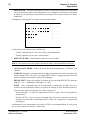
L'appui sur "F+" ou "F-" (1) affiche le menu suivant :
C U S T O M
F U N C T I O N S
- - - - - - - - S A V E - - - >G O
T O
B A S I C
P R E S E T
P I C T U R E
R E C A L L
S T O R E
- - - -
MO D E
C U S T O M
C U S T O M
F I L E
F I
L E
>
>
P R G M
M A R K E R
1
:
- - >
P R G M
M A R K E R
2
:
- - >
A S P E C T
R A T I O
: - - - -
V F
S E L E C T
: - - - -
MO N
S E L E C T
: - - - -
MO N
C H A R A C
:
- - -
:
- - -
:
- - -
:
- - >
H
S C
P H A S E
P H A S E
D I A G N O S T I C
Avec l'interrupteur "F+ F-", déplacer le curseur et sélectionner la fonction "GO TO BASIC
MODE". Valider ensuite cette fonction avec les touches "+" ou "-" (7). La caméra fonctionne maintenant en mode "BASIC".
2.2.4.2 - Mode "CUSTOM"
La caméra est en mode "BASIC".
Le passage vers le mode "CUSTOM" peut s'effectuer l'interrupteur "SAVE ON" étant en
position "SAVE" ou en position "ON".
Positionner la caméra en "MIRE DE BARRES" puis actionner l'interrupteur "WHT BLK",
situé en face avant de la caméra, vers le bas. Le menu suivant s'affiche :
TTV 1657D BAS IC
--- - -- - -- - -- - -- - -- - ->GO TOCUSTOMMODE La fonction "GO TO CUSTOM MODE" est sélectionnée. Valider ensuite cette fonction
avec les touches "+" ou "-" (7). Un "V" s'affiche fugitivement à droite de la fonction et le
menu disparaît. La caméra fonctionne maintenant en mode "CUSTOM".
B1657D902C
Septembre 2000
THOMSON TTV 1657D
Manuel utilisateur
46
Chapitre 2 - Caméra
Exploitation
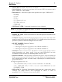
2.2.5 - Exploitation en mode "BASIC"
Arborescence des différents menus :
Se référer au paragraphe
2.2.8.2 -"Fonctions MARKERS"
Se référer au paragraphe
2.2.8.1 -"Fonctions principales"
B A S I C
F U N C T I O N S
- - - - - - - - - S A V E - - >P R E S E T
SAVE
F+, F-
- - - - -
P I C T U R E
P R G M
M A R K E R
1
:
- - >
P R G M
M A R K E R
2
:
- - >
A S P E C T
R A T I O
+ -
: - - - :
ON
SAVE
ON
F+, F-
BASIC FUNCTIONS
--- - -- - --ON- - -- - -- - ->SHUTTER : - - SHUTTER SPEED : - - - CLEAR SCAN : - - CL SC SPEED : - - - EFFECT FILTER : - - - NEUTRAL FILTER : - - -
PRGMMARKERS
--- - -- - -- - -- - -- - -- - - >EXIT
CROSS CENTER : - - SAFE ZONE : - - OPPOSITE FORMAT: - --
TOP BARGR. : - - BOT BARGR. : - --
BOX : - --
H POS BOX : - --
V POS BOX : - --
WIDTH BOX : - --
HEIGHT BOX : - --
TTV 1657D BAS IC
--- - -- - -- - -- - -- - -- - ->GO TOCUSTOMMODE COLOR BAR
+
BLACK BALANCE
+ -
CUSTOM MODE
Se référer au paragraphe
2.2.9 -"Signification des status"
SAVE
ON
PICT when STATUS
PICTURE
BASIC
ND.F: - -- - F : - - . - GAIN: - -DB SHUT: - -- - V. IN: - -V- WARNING: X X
F+, F-
STATUS
EF.F: -- - FX2 : -- WBL: - : -- - CS : -- - VERS. : -- - -
PICT
PICT
A
WBL
F-
B
WHT
BLK
+-
VTR
PRST
+
GAIN
-
F+
SAVE
ON
ON
SAVE
THOMSON TTV 1657D
Manuel utilisateur
+ -
B1657D902C
Septembre 2000
Chapitre 2 - Caméra
Exploitation
47
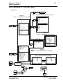
2.2.6 - Exploitation en mode "CUSTOM"
Arborescence des différents menus :
+ -
BASIC MODE
Se référer au paragraphe
2.2.8.4 -"Fonctions CUSTOM FILE"
Se référer au paragraphe
2.2.8.1 -"Fonctions principales"
RECALL CUSTOM FILE
--- - -- - -- - -- - -- - -- - - >FILE 1 FILE 2
FILE 3
FILE 4
EXIT
+ -
C U S T O M
F U N C T I O N S
- - - - - - - - S A V E - - - >G O
SAVE
F+, F-
T O
B A S I C
P I C T U R E
R E C A L L
C U S T O M
S T O R E
- - - -
C U S T O M
F I L E
F I
L E
>
M A R K E R
1
:
- - >
P R G M
M A R K E R
2
:
- - >
R A T I O
: - - - -
V F
S E L E C T
: - - - -
MO N
S E L E C T
: - - - -
MO N
C H A R A C
H
P H A S E
S C
+ -
>
P R G M
A S P E C T
STORE CUSTOM F ILE
--- - -- - -- - -- - -- - -- - - >FILE 1 FILE 2
FILE 3
FILE 4
EXIT
MO D E
P R E S E T
P H A S E
D I A G N O S T I C
:
- - -
:
- - -
:
- - -
:
- - >
Se référer au paragraphe
2.2.8.2 -"Fonctions MARKERS"
PRGMMARKERS
--- - -- - -- - -- - -- - -- - - >EXIT
CROSS CENTER : - - SAFE ZONE : - - OPPOSITE FORMAT: - --
TOP BARGR. : - - BOT BARGR. : - --
BOX : - --
H POS BOX : - --
V POS BOX : - --
WIDTH BOX : - --
HEIGHT BOX : - --
+ DIAGNOSTICS
--- - -- - -- - -- - -- - -- - - ANALOGPROCESS : - - - DIGIT. PROCESS : - - - ENCODER : - - - POWER : - - --
+ -
ON
SAVE
ON
F+, F-
CUSTOM FUNCTI ONS
--- - -- -ON- -CFX. * -- - >SHUTTER : - - SHUTTER SPEED : - - - CLEAR SCAN : - - CL SC SPEED : - - - KNEE : - - - ABL : - - DFZ : - --
DFZ WIDEorTELE : - - IRISOFFSET : - - COLOR TEMP (K) : - - - EFFECT FILTER : - - - NEUTRAL FILTER : - - --
MASTERPED : - - DETAIL LEVEL : - - SKIN DETAIL : - - SKIN DTL LVL : - - SKIN VIEW : - - SKIN ACQUIS. : - --
STATUS
PICT when
PICTURE
Se référer au paragraphe
2.2.8.3 -"Exploitation et fonctions du SKIN"
Se référer au paragraphe
2.2.9 -"Signification des status"
CUSTOM
ND.F: - -- - F : - - . - I+/ - : -- - GAIN: - -DB KNEE: - -- - SHUT: - -- - WARNING: X X
STATUS
EF.F: -- - FX2 : - - DFZ : - - WBL: - : -- - DTL : - - -
CS : -- - + -
NEXT
SK.DTL:- - -
PED : - - -
VF : - - -
V IN: - -V- CA : - - -
VERS. : -- - -
WARNING: X X
CF : - . ABL : - - MONI : - - GEN-LK: - - -
CMD : - - HEAD: - - -
PREVIEW
F+, FPICT
PICT
A
WBL
F-
WHT
BLK
+-
VTR
B
PRST
+
GAIN
-
SAVE
ON
B1657D902C
Septembre 2000
F+
ON
SAVE
+ -
THOMSON TTV 1657D
Manuel utilisateur
48
Chapitre 2 - Caméra
Exploitation
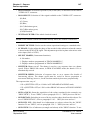
2.2.7 - Fonctions d'exploitation cadreur avec un OCP
Si la caméra est exploitée avec un pupitre type OCP 40/42 connecté sur la prise
"REMOTE" ou sur un contrôle de voie, le cadreur dispose des fonctions suivantes :
Arborescence des différents fonctions :
Se référer au paragraphe
2.2.8.1 -"Fonctions principales"
SAVE
ON
F+, F-
>SELECT MARKER PRGMMARKER 1 PRGMMARKER 2 VF SELECT MONSELECT MONCHARAC EFFECT FILTER
NEUTRAL FILTER
STATUS : - --
: - ->
: - ->
: - - --
: - - -: - --
: - - -: - - -:
Se référer au paragraphe
2.2.8.2 -"Fonctions MARKERS"
+ -
PRGMMARKERS
--- - -- - -- - -- - -- - -- - - >EXIT
CROSS CENTER : - - SAFE ZONE : - - OPPOSITE FORMAT: - --
TOP BARGR. : - - BOT BARGR. : - --
BOX : - --
H POS BOX : - --
V POS BOX : - --
WIDTH BOX : - --
HEIGHT BOX : - --
Se référer au paragraphe
2.2.9 -"Signification des status"
PICT
CUSTOM
ND.F: - -- - F : - - . - I+/ - : -- - GAIN: - -DB KNEE: - -- - SHUT: - -- - WARNING: X X
F+, F-
STATUS
EF.F: -- - FX2 : - - DFZ : - - WBL: - : -- - DTL : - - -
CS : -- - NEXT
+ -
SK.DTL:- - -
PED : - - -
VF : - - -
V IN: - -V- CA : - - -
VERS. : -- - -
WARNING: X X
PICT
PICT
A
WBL
F-
B
CF : - . ABL : - - MONI : - - GEN-LK: - - -
CMD : - - HEAD: - - -
PREVIEW
WHT
BLK
+-
VTR
PRST
+
GAIN
-
F+
SAVE
ON
ON
SAVE
+ -
NOTA : En EFP avec un adaptateur type CA85, l'appui sur la touche "+" sélectionne la
vidéo "EXT" et l'appui sur la touche "-" sélectionne la vidéo "MIX".
THOMSON TTV 1657D
Manuel utilisateur
B1657D902C
Septembre 2000
Chapitre 2 - Caméra
Exploitation
49
2.2.8 - Signification des réglages d’exploitation
2.2.8.1 - Fonctions principales
• ABL : (Automatic black level). Mise en ou hors service de l'automatisme permettant
d'aligner la partie la plus sombre de l'image sur le niveau du noir. Cet automatisme
donne un contraste maximum à l'image, utile par exemple dans le cas de prise de vue
par temps de brouillard.
• ASPECT RATIO : Sélection du format 4/3 ou 16/9.
NOTA :La caméra possède des mémoires de balances des blancs et des noirs différentes
entre les formats 4/3 et 16/9.
• CLEAR SCAN : Mise en ou hors service du clear scan. Le clear scan permet de faire
varier le temps d'exposition d'une façon quasiment linéaire (voir CL SC SPEED).
• CL SC SPEED : Choix du temps d'exposition de façon à avoir une image uniformément
exposée, lors de prise de vue d'images issues de moniteur asynchrone par rapport à la
caméra, comme par exemple les images informatiques. Pour choisir le temps
d'exposition, faire varier la vitesse du clear scan afin d'avoir une image stable dans le
viseur. Les temps proposés vont d'environ 1/50,3 Hz à 1/200 Hz et dépendent du type
de capteur CCD équipant la caméra.
• COLOR TEMP : Indique la valeur de la température de couleur contenue dans la
mémoire de balance des blancs. L'exploitant peut modifier cette température pour
rendre l'image plus "chaude" ou plus "froide".
• DETAIL LEVEL : Permet de modifier le réglage du niveau de détail de l'image.
• DFZ : (Detail follow zoom) .Mise en ou hors service de l'automatisme permettant
d'asservir le niveau de détail de l'image à la focale. Cet automatisme permet, par
exemple, de diminuer le détail en position "Téléobjectif" afin de rendre l'image plus
douce.
• DFZ TELE WIDE : Réglage du niveau de contour en position "Téléobjectif" ou
"Grand Angle", suivant l'affichage. La commutation "TELE" "WIDE" se fait à micourse du zoom.
NOTA : DFZ doit être "ON" et l'objectif doit envoyer à la caméra l'indication de position
du Zoom.
B1657D902C
Septembre 2000
THOMSON TTV 1657D
Manuel utilisateur
50
Chapitre 2 - Caméra
Exploitation
• DIAGNOSTIC : Fonction permettant de tester le bon fonctionnement des différentes
cartes du traitement vidéo et de l'alimentation. La validation cette fonction sélectionne
le signal test (les paramètres d'exploitation sont mémorisés et seront restitués à la fin du
diagnostic).
Le diagnostic étant terminé le compte rendu suivant s'affiche :
DIAGNOSTICS
--- - -- - -- - -- - -- - -- - - ANALOGPROCESS : - - - DIGIT. PROCESS : - - - ENCODER : - - - POWER : - - -
A droite du nom de chaque carte s'affiche soit :
- "PASS" signifiant que la carte est en état de fonctionnement,
- "BAD" signifiant que la carte est défectueuse.
• EFFECT FILTER : Commande électrique de la roue d'effets.
NOTA : Si la caméra n'est pas équipée de filtres d’effets, cette commande est inactive.
• GO TO BASIC MODE : Permet de passer du mode d'exploitation "CUSTOM" vers
"BASIC".
• H PHASE : Réglage permettant d'ajuster la phase horizontale de la base de temps de la
caméra quand celle ci est asservie au signal GEN LOCK. Ce réglage permet d'avoir des
signaux en phase horizontale à l'entrée du mélangeur.
• IRIS OFFSET : Permet de modifier l'ouverture de l'iris en mode IRIS AUTO, dans une
plage de + ou - 1 diaphragme (affichage 0 à - 100).
• KNEE : Cette commande agit sur le dispositif de compression au blanc qui sert à
restituer sur une dynamique réduite, les parties de l'image les plus fortement éclairées,
tout en conservant la colorimétrie des zones compressées.
- Position MANU : le seuil de compression est fixe et réglé à 700 mV (ajustable en
maintenance).
- Position AUTO : C'est le contenu de l'image dont le niveau est au dessus du niveau
nominal qui détermine automatiquement le début de compression (compresseur
dynamique).
L'utilisation de cette automatisme en position AUTO est recommandé dans le cas de prise
de vue à fort contraste (exemple : contre-jour).
THOMSON TTV 1657D
Manuel utilisateur
B1657D902C
Septembre 2000
Chapitre 2 - Caméra
Exploitation
51
• MASTER PED : Réglage du niveau de noir général.
• MON CHARAC : Sélection de la présence (ON) ou non (OFF) des caractères sur la
prise "VIDEO OUT" de la caméra.
• MON SELECT : Sélection du signal vidéo disponible sur la prise "VIDEO OUT" :
- (R) Rouge,
- (G) Vert,
- (B) Bleu,
- (R-G) Rouge moins vert,
- (B-G) Bleu moins vert,
- (COD) Codé.
• NEUTRAL FILTER : Commande électrique de la roue de densité.
NOTA : Si la caméra est équipée de filtres de densité à commande manuelle cette
commande est inactive.
• PRESET PICTURE : Permet de positionner les différents réglages d'exploitation à une
valeur standard.
• SC PHASE : Réglage permettant d'ajuster la phase de la sous porteuse de la vidéo codée
quand la caméra est asservie au signal GEN LOCK. Ce réglage permet d'avoir des sous
porteuses en phase à l'entrée du mélangeur (PAL ou NTSC).
• SELECT MARKER (Fonctions Cadreur) :
- 0 : Aucun marqueur,
- 1 : Affichage des marqueurs programmés dans "PRGM MARKER 1",
- 2 : Affichage des marqueurs programmés dans "PRGM MARKER 2",
• SHUTTER : Mise en ou hors service du shutter. Le shutter permet de faire varier le
temps d'exposition (voir shutter speed). Avec une caméra PROSCAN en mode
SCANNING: FILM, le shutter est automatiquement activé au 1/50 s.
• SHUTTER SPEED : Choix du temps d'exposition de façon à saisir des détails fins
d'objet en mouvement rapide. Il faut choisir des temps d'obturation d'autant plus faible
que le déplacement est rapide en tenant compte cependant que la sensibilité diminue
proportionnellement.
Le temps d'exposition varie de :
- 1/50 s (SHUTTER: OFF) à 1/1000 s en mode SCANNING : STANDARD,
- 1/25 s (SHUTTER: OFF) à 1/500 s avec une caméra PROSCAN en mode
SCANNING : FILM.
• SKIN ACQUIS : Déclenche l'automatisme d'acquisition de la teinte cadrée dans le
rectangle (voir "SKIN VIEW"). Pour l'exploitation du "SKIN", se référer au
paragraphe 2.2.8.3 -"Exploitation et fonctions du SKIN".
B1657D902C
Septembre 2000
THOMSON TTV 1657D
Manuel utilisateur
52
Chapitre 2 - Caméra
Exploitation
• SKIN DETAIL : Mise en ou hors service du dispositif permettant de diminuer le détail
sur les teintes chairs. Pour l'exploitation du "SKIN", se référer au paragraphe 2.2.8.3 "Exploitation et fonctions du SKIN".
• SKIN DTL LVL : Réglage du niveau de détail sur la teinte sélectionnée par la fonction
"SKIN". Pour l'exploitation du "SKIN", se référer au paragraphe 2.2.8.3 -"Exploitation
et fonctions du SKIN".
• SKIN VIEW : Mise en service des indicateurs (rectangle et zébras) de la fonction
"SKIN". Pour l'exploitation du "SKIN", se référer au paragraphe 2.2.8.3 -"Exploitation
et fonctions du SKIN".
• STATUS : Affichage dans le viseur de la configuration de la caméra. Se référer au
paragraphe 2.2.9 -"Signification des status".
• VF SELECT : Sélection du signal vidéo viseur :
- (Y) Luminance,
- (R) Rouge,
- (G) Vert,
- (B) Bleu,
- (R-G) Rouge moins vert,
- (B-G) Bleu moins vert,
- Externe (sélectionné par le commutateur "RET" de l'objectif ou sur le côté gauche du
CA85).
NOTA : Les vidéos R, G, B ne sont pas disponibles si la mire de barres est sélectionnée et
sont remplacées par la vidéo Y.
THOMSON TTV 1657D
Manuel utilisateur
B1657D902C
Septembre 2000
Chapitre 2 - Caméra
Exploitation
53
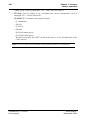
2.2.8.2 - Fonctions MARKERS
• PRGM MARKER 1 : Permet de choisir les différents types de marqueurs (MARK1)
dont la mise en service est commandée par :
- le commutateur "ZEBRA-MARK" en face avant du viseur 1,5",
- la fonction "SELECT MARKER" du menu cadreur lorsque la caméra est commandé
à partir d'un OCP.
La validation de cette fonction affiche le sous menu suivant :
PRGMMARKERS
--- - -- - -- - -- - -- - -- - - >EXIT
CROSS CENTER : - - SAFE ZONE : - - OPPOSITE FORMAT: - --
TOP BARGR. : - - BOT BARGR. : - --
BOX : - --
H POS BOX : - --
V POS BOX : - --
WIDTH BOX : - --
HEIGHT BOX : - --
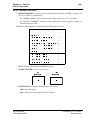
• EXIT : Sortie du menu "PRGM MARKERS".
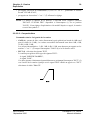
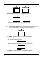
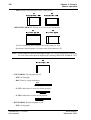
• CROSS CENTER : Mise en ou hors service de la croix centrale :
4/3
Center cross
16/9
Center cross
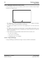
• SAFE ZONE : Mise en ou hors service du rectangle délimitant la zone de sauvegarde :
- OFF : pas de zone de sauvegarde,
- 90 % : la zone de sauvegarde représente 90 % de l'image,
B1657D902C
Septembre 2000
THOMSON TTV 1657D
Manuel utilisateur
54
Chapitre 2 - Caméra
Exploitation
- 100 % : la zone de sauvegarde représente 100 % de l'image.
4/3
Safety zone: 90 (or 100%)
16/9
Safety zone: (90 or) 100%
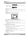
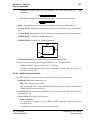
• OPPOSITE FORMAT : Mise en service de deux traits pointillés :
4/3
16/9
Opposite format 4/3
Opposite format 16/9
- Verticaux servant de repère format 4/3 si la caméra est en 16/9.
- Horizontaux servant de repère format 16/9 si la caméra est en 4/3.
NOTA : Si la caméra est exploitée en 16/9, des marqueurs verticaux servant de repère
14/9 peuvent être affichés en sélectionnant OPPOSITE FORMAT : 14/9.
16/9
Opposite format 14/9
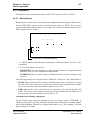
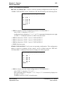
• TOP BARGR. : Mise en/hors service et choix du bargraphe supérieur :
- OFF : pas de bargraphe.
- BAT : indication de la tension Batterie :
10,8V
10V
12V
17V
- Z.CEN : indication de la position du zoom en représentation centrée :
- Z.LEF : indication de la position du zoom en représentation à gauche :
• BOT BARGR. : mise en/hors service et choix du bargraphe inférieur :
- OFF : pas de bargraphe,
THOMSON TTV 1657D
Manuel utilisateur
B1657D902C
Septembre 2000
Chapitre 2 - Caméra
Exploitation
55
- AUDIO : niveau audio d'enregistrement sur le canal 1 du magnétoscope (avec repères
0 dB et - 3 dB) :
-16dB
-3dB 0dB
+3dB
- FOCUS : indicateur de la position de la bague de mise au point (seulement si
l'objectif est équipé d'une recopie de position) :
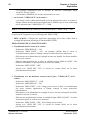
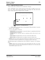
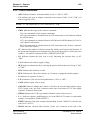
• BOX : Mise en ou hors service du cadre ajustable.
• H. POS. BOX : Réglage de la position horizontale du coin inférieur gauche du cadre
ajustable.
• V. POS. BOX : Réglage de la position verticale du coin inférieur gauche du cadre
ajustable.
• WIDTH BOX : Réglage de la largeur du cadre ajustable.
• HEIGHT BOX : Réglage de la hauteur du cadre ajustable.
WIDTH
HEIGHT
V. POS.
H. POS.
• PRGM MARKER 2 : (Fonctions identiques au PRGM MARKER 1).
Permet de choisir les différents types de marqueurs (MARK2) dont la mise en service est
commandée par :
- le commutateur "ZEBRA-MARK" en face avant du viseur 1,5",
- la fonction "SELECT MARKER" du menu cadreur lorsque la caméra est commandé
à partir d'un OCP.
2.2.8.3 - Exploitation et fonctions du SKIN
La fonction SKIN permet d'associer un niveau de détail à une teinte déterminée de l'image.
• SKIN DETAIL : Mise en/hors service de la fonction "SKIN" :
- OFF : pas d'action de la fonction SKIN,
- ON : le réglage "SKIN DTL LVL" modifie le niveau de détail sur la teinte
sélectionnée par l'automatisme "SKIN ACQUIS.".
• SKIN DTL LVL : Réglage du niveau de détail sur la teinte sélectionnée par
l'automatisme "SKIN ACQUIS.".
• SKIN VIEW : La position ON affiche :
- dans le viseur :
B1657D902C
Septembre 2000
THOMSON TTV 1657D
Manuel utilisateur
56
Chapitre 2 - Caméra
Exploitation
- un rectangle d'acquisition pour la fonction de détection automatique SKIN
ACQUIS., décrite ci après.
- des hachures (ZEBRAS) sur la teinte sélectionnée en cours,
• sur la sortie "VIDEO OUT" de la caméra :
- une image en noir et blanc dans laquelle peuvent apparaître des zones en couleur si
l'image contient la teinte mémorisée auparavant (à condition que le sortie monitoring
soit en position codée "MON SELECT" = COD).
NOTA : Il est déconseillé de commencer un enregistrement si "SKIN VIEW" = ON.
La position OFF supprime tous les affichages du "SKIN VIEW".
• SKIN ACQUIS. : Effectue une acquisition automatique de la teinte cadrée dans le
rectangle d'acquisition affiché par la fonction SKIN VIEW.
EXPLOITATION DE LA FONCTION SKIN
1. Visualisation dans le viseur de la caméra
- Positionner "SKIN DETAIL" = ON.
- Positionner "SKIN VIEW" = ON : un rectangle s'affiche dans le viseur et,
éventuellement des zébras si l'image contient la teinte mémorisée auparavant.
- Sélectionner en la cadrant dans le rectangle la teinte sur laquelle l'on désire modifier
le niveau de contour.
- Effectuer une acquisition de la teinte en validant la ligne 'SKIN ACQUIS.". Des
hachures (ZEBRAS) se superposent sur la teinte sélectionnée.
- Positionner "SKIN VIEW" = OFF.
- Ajuster avec "SKIN DTL LVL" le niveau de contour désiré sur la teinte
précédemment sélectionnée.
2. Visualisation avec un moniteur connecté sur la prise "VIDEO OUT" de la
caméra
- Positionner "MON SELECT" = COD.
- Positionner "SKIN DETAIL" = ON.
- Positionner "SKIN VIEW" = ON : l'image passe en noir et blanc et éventuellement
des zones couleurs apparaissent si l'image contient la teinte mémorisée
précédemment.
- Sélectionner, en la cadrant dans le rectangle du viseur, la teinte sur laquelle l'on désire
modifier le niveau de contour.
- Effectuer une acquisition de la teinte en validant la ligne 'SKIN ACQUIS.". La teinte
sélectionnée passe en couleur sur le moniteur.
- Positionner "SKIN VIEW" = OFF. Toute l'image est en couleur.
- Ajuster avec "SKIN DTL LVL" le niveau de contour désiré sur la teinte
précédemment sélectionnée.
THOMSON TTV 1657D
Manuel utilisateur
B1657D902C
Septembre 2000
Chapitre 2 - Caméra
Exploitation
57
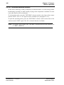
2.2.8.4 - Fonctions CUSTOM FILE
RECALL CUSTOM FILE : Permet de rappeler une configuration d'exploitation mémorisée au moyen du menu "STORE CUSTOM FILE". La validation de cette fonction affiche
le menu suivant :
RECALL CUSTOM FILE
--- - -- - -- - -- - -- - -- - - >FILE 1 FILE 2
FILE 3
FILE 4
EXIT
• FILE 1 : Permet de rappeler la configuration mémorisée dans "CUSTOM FILE 1":
- sélectionner "FILE 1" avec les touches "F+ ou F-",
- valider le choix avec les touches "+ -". Un "V" s'affiche alors fugitivement à droite
de "FILE 1". La validation entraîne un "EXIT" de ce menu.
• FILE 2 : Identique à "FILE 1" mais pour "CUSTOM FILE 2".
• FILE 3 : Identique à "FILE 1" mais pour "CUSTOM FILE 3".
• FILE 4 : Identique à "FILE 1" mais pour "CUSTOM FILE 4".
• EXIT : Sortie du menu.
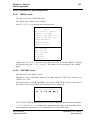
STORE CUSTOM FILE : Permet de mémoriser une configuration d'exploitation. Cette
configuration, sauvegardée à la mise hors tension de la caméra, pourra être rappeler ultérieurement au moyen du menu "RECALL CUSTOM FILE". La validation de cette fonction affiche le menu suivant :
STORE CUSTOM F ILE
--- - -- - -- - -- - -- - -- - - >FILE 1 FILE 2
FILE 3
FILE 4
EXIT
• FILE 1 : Permet de mémoriser dans "CUSTOM FILE 1" la configuration en cours :
- sélectionner "FILE 1" avec les touches "F+ F-",
- valider ensuite le choix avec les touches "+ -". Un "V" s'affiche alors fugitivement à
B1657D902C
Septembre 2000
THOMSON TTV 1657D
Manuel utilisateur
58
Chapitre 2 - Caméra
Exploitation
droite de "FILE 1". La validation entraîne un "EXIT" de ce menu.
• FILE 2 : Identique à "FILE 1" mais pour "CUSTOM FILE 2".
• FILE 3 : Identique à "FILE 1" mais pour "CUSTOM FILE 3".
• FILE 4 : Identique à "FILE 1" mais pour "CUSTOM FILE 4".
• EXIT : Sortie du menu.
THOMSON TTV 1657D
Manuel utilisateur
B1657D902C
Septembre 2000
Chapitre 2 - Caméra
Exploitation
59
2.2.9 - Signification des status
• ABL : Indique si l'"Automatique Black Level" est en service : "ON", ou hors service:
"OFF".
• CA : Indique le type d'adaptateur connecté sur la caméra (CA85, CA25, VTR, ou si
aucun n'est reconnu: CA ?).
NOTA : Un VTR connecté sur un CA25 est indiqué "VTR".
• CMD : Indique l'origine des commandes de la caméra :
- LOC : les commandes sont celles de la caméra,
- OCP : les commandes sont issues d'un OCP connecté sur une voie 1625, sans option
APCM,
- CCU : les commandes sont issue d'une carte APCM (Voie APCM du CA85 ou voie
1625 avec l'option),
- EXT : les commandes sont issue d'un OCP connecté sur la prise "remote" sur le coté
de la caméra.
• CF : Indique le numéro de la dernière CUSTOM FILE rappelée (fonction RECALL
CUSTOM FILE). Si un réglage d'exploitation a été modifié depuis ce rappel, le numéro
est suivi du symbole *. Aucun numéro n'est affiché après un "PRESET PICTURE".
• CS : Indique si le clear scan est en service en indiquant le temps d'exposition, ou hors
service : "OFF".
• V IN : Indique la valeur de la tension d'alimentation que reçoit la caméra.
• DFZ : Indique si le dispositif permettant d'asservir le niveau de détail de l'image à la
focale du zoom est en service : "ON", ou hors service : "OFF".
• DTL : Indique la valeur du niveau de détail.
• EF.F : Indique le numéro de filtre d’effets en service (si la caméra est équipée de cette
option).
• F : Indique l'ouverture de l'iris.
• F X 2 : Indique si le doubleur de focale de l'objectif est en service: "ON", ou hors
service : "OFF".
• GAIN : Indique la valeur du gain par bonds.
• GEN-LK : Indique si la caméra est asservie sur un signal extérieur, et son origine : EXT
si l'origine est la prise "gen lock" sur le côté de la caméra, CCU si l'origine est un
contrôle de voie.
• HEAD : Indique le numéro du type de CCD équipant la caméra (utilisation usine).
• I +/- : Indique la modification d'ouverture apportée sur l'iris en mode IRIS AUTO
(correspond à "IRIS OFFSET" dans les réglages d'exploitation).
• KNEE : Indique si le seuil de déclenchement du compresseur aux blancs est fixe:
B1657D902C
Septembre 2000
THOMSON TTV 1657D
Manuel utilisateur
60
Chapitre 2 - Caméra
Exploitation
"MANU", ou asservi sur le niveau vidéo : "AUTO".
• MONI : Indique la vidéo moniteur sélectionnée (prise "vidéo out" sur le côté de la
caméra).
• ND.F : Indique le numéro de filtre de densité en service.
• NEXT : Informe que l'affichage des status se poursuit sur une 2ème page. Dans ce cas,
l'appui sur "+" ou "-" en face avant de la caméra affiche la 2ème page.
• PED : Indique la valeur du master ped.
• PREVIOUS : Informe que l'affichage est la 2ème page des status. Dans ce cas, l'appui
sur "+" ou "-" en face avant de la caméra affiche la 1ère page.
• SHUT : Indique si le shutter est en service en indiquant le temps d'exposition, ou hors
service : "OFF".
• SK.DTL : Indique si le dispositif permettant de diminuer le niveau de détail sur les
teintes chairs est en service : "ON", ou hors service: "OFF".
• VERS. : Indique le numéro de version SOFT équipant la caméra.
• VF : Indique la vidéo viseur sélectionnée.
• WARNING : Indique le nombre de "warning". Le "warning" est une alarme pour
prévenir l'utilisateur qu'un réglage d'exploitation n'est pas en position nominal, ou que
la tension d'alimentation de la caméra est trop faible.
- Les réglages d'exploitation provoquant un "warning" sont: filtre d'effet ≠ clear, filtre
de densité ≠ clear, extender ON, offset iris (I +/-) ≠ 50, DFZ ON, gain par bonds ≠
0db, knee OFF (suite à une opération de maintenance) ou AUTO, valeur du détail
OFF (suite à une opération de maintenance), shutter ON, clear scan ON, skin detail
ON, ABL ON.
- Le(s) réglage(s) "en warning" sont signalés par un point d'exclamation ("!") qui
s'affiche à la place des deux points (":") suivant le réglage.
- Pour la tension d'alimentation, le "!" sera clignotant lorsque la batterie est presque
épuisée.
• WBL : Indique la mémoire ("A" ou "B") de balance des blancs sélectionnée, suivie de
la température de couleurs calculée. Si la balance est en position "PRESET", s'affiche
"P" suivi de "3100" ou "5600" indiquant le type de preset (clear ou day).
THOMSON TTV 1657D
Manuel utilisateur
B1657D902C
Septembre 2000
Chapitre 3 - Viseurs
61
Chapitre 3
Viseurs
3.1 - Viseur 4 cm .................................................................... 63
3.1.1 - Commandes et fonctions .....................................................................
3.1.2 - Signalisations lumineuses ...................................................................
3.1.3 - Réglages électriques ...........................................................................
3.1.4 - Réglages mécaniques .........................................................................
63
65
66
67
3.2 - Viseur 14 cm .................................................................. 69
3.2.1 - Principales caractéristiques .................................................................
3.2.2 - Accessoires .........................................................................................
3.2.3 - Description générale............................................................................
3.2.4 - Description des commandes ...............................................................
3.2.5 - Montage du viseur sur son support .....................................................
B1657D902C
Septembre 2000
69
70
70
71
73
THOMSON TTV 1657D
Manuel utilisateur
62
THOMSON TTV 1657D
Manuel utilisateur
Chapitre 3 - Viseurs
B1657D902C
Septembre 2000
Chapitre 3 - Viseurs
Viseur 4 cm
63
3.1 - VISEUR 4 CM
3.1.1 - Commandes et fonctions
1
2
3
4
5
PEAK
12
CONT
BRIGHT
6
7
8
9
11
10
1 - Bague de mise au point
2 - Oeilleton
3 - Potentiomètre "AUDIO"
Permet de régler le niveau d'enregistrement du canal 1 du magnétoscope ßSP TTV3505
(BVV5).
4 - Commutateur "LOW-TALLY OFF HIGH"
Cet inverseur à trois positions permet le choix entre deux intensités lumineuses et l'inhibition du voyant extérieur "TALLY" situé en face avant du viseur. Ce commutateur n'a
aucune action sur l'indication d'enregistrement visible dans le viseur.
5 - Commutateur "ZEBRA -MARK"
Cet inverseur à trois positions (à retour automatique en position centrale) permet de mettre
en service :
1. A la première pression vers "ZEBRA" les "zébras", à la deuxième pression le "Level
Vidéo Indicator", et à la troisième pression l'affichage s'éteint.
Les "zébras" sont des hachures superposées aux parties d’image dont la luminance
est égale à xx %* ou 100 % du niveau du blanc.
En configuration ENG, la sélection xx %* ou 100 % s'effectue en appuyant sur les
touches "+ "ou " -" en face avant de la caméra si le zébra est la dernière fonction ayant
été mise en service.
En configuration EFP, la sélection xx %* ou 10 0% est la dernière utilisé en ENG.
B1657D902C
Septembre 2000
THOMSON TTV 1657D
Manuel utilisateur
64
Chapitre 3 - Viseurs
Viseur 4 cm
La position xx % affiche la valeur du zébra réglable en maintenance.
Le "Level Vidéo Indicator" est une indication représentant la valeur de la luminance
ligne à ligne. Ces indications sont particulièrement utiles pour régler manuellement
l’ouverture d’iris de l’objectif (mode IRIS MAN).
BLACK
WHITE
700 mV
Level Video Indicator
2. A la première pression vers "MARK" s'affiche les marqueurs 1, à la deuxième
pression s'affiche les marqueurs 2, et à la troisième pression l'affichage s'éteint. Le
contenu des marqueurs est programmable dans les menus d'exploitation. (Voir
chapitre 2, "Exploitation" paragraphe "Fonctions MARKERS").
6 - Potentiomètre "BRIGHT"
Réglage de LUMIÈRE du viseur.
7 - Potentiomètre "CONT"
Réglage de CONTRASTE du viseur.
8 - Potentiomètre "PEAK"
Réglage de renforcement des transitions de l’image sur l’écran du viseur, afin de faciliter
les réglages de mise au point.
9 - Verrou de sécurité de fixation du viseur
Pour désolidariser le viseur de la caméra tirer le verrou vers le bas.
10 - Queue d'arronde femelle de fixation du viseur
11 - Bague de verrouillage du doublet
Pour extraire le doublet tourner la bague dans le sens indiqué sur le dessin et tirer.
12 - Voyant ON AIR 1
Ce voyant s'allume dans les mêmes conditions que l'indication "REC" décrite ci après.
THOMSON TTV 1657D
Manuel utilisateur
B1657D902C
Septembre 2000
Chapitre 3 - Viseurs
Viseur 4 cm
65
3.1.2 - Signalisations lumineuses
1
4
BAT
2
3
1 - Indication "PREVIEW"
Ce voyant s'allume lorsqu'en EFP la caméra est en préparation avant de passer à l'antenne.
2 - Indication "HORS STANDARD"
Ce voyant s'allume pour prévenir l'opérateur que la caméra n'est pas en configuration standard :
• Shutter ON,
• Clear scan ON,
• ABL ON,
• Extender ON,
• Gain différent de 0 dB,
• Iris offset différent de 0,
• Skin détail ON,
• Détail OFF (suite à une opération de maintenance).
3 - Indication "BATTERIE"
Cette information est délivrée par le magnétoscope fixé sur la caméra, ou par le CA25 en
configuration CA25 + magnétoscope.
Ce voyant est normalement éteint. Il clignote lorsque la tension d’alimentation devient
inférieure à 11,5 V. Son allumage est permanent quand la tension est inférieure à 11 V. Voir
tableau ci-après.
4 - Indication "REC"
En configuration caméra + contrôle de voie :
• ce voyant est allumé lorsque l'équipement est "ON AIR" ou lors d’un appel de
l’Opérateur du pupitre.
B1657D902C
Septembre 2000
THOMSON TTV 1657D
Manuel utilisateur
66
Chapitre 3 - Viseurs
Viseur 4 cm
En configuration caméra + magnétoscope :
• l’allumage de ce voyant est permanent pendant l’enregistrement,
• avec un TTV3505 (BVV5), le voyant clignote quand un témoin d’avertissement du
magnétoscope est allumé: approche de la fin de bande, fin de bande, batterie presque
déchargée, batterie déchargée, enregistrement incorrect (RF), asservissement du
cabestan non verrouillé (SERVO), condensation (HUMID), tension de bande
anormalement faible (SLACK) (Cf. Notice d’exploitation du magnétoscope).
TTV 3505
Voyants
d’avertissement
Indications viseur
REC
Causes
BATT
RF
4
Les têtes sont sales
SERVO
4
Irrégularités dans l’asservissement
HUMID
4
Condensation
SLACK
4
Bande détendue
TAPE END
1
4
La bande est presque à sa fin
Fin de bande
BATT
1
4
1
A
Batterie presque épuisée
Batterie épuisée
Légende :
A = Allumage continu
l = Clignotement à 1 Hz
4 = Clignotement à 4 Hz
3.1.3 - Réglages électriques
Réglages des potentiomètres "BRIGHT" et "CONT" :
1. Mettre la caméra en "mire de barres".
2. Mettre le potentiomètre "CONT" au minimum et régler le potentiomètre "BRIGHT"
pour être à la limite de visibilité de la barre la plus sombre de la mire.
3. Régler le potentiomètre "CONT" pour voir toutes les barres de la mire, sans
saturation de la barre la plus blanche.
THOMSON TTV 1657D
Manuel utilisateur
B1657D902C
Septembre 2000
Chapitre 3 - Viseurs
Viseur 4 cm
67
3.1.4 - Réglages mécaniques
2
1
Pour adapter le viseur à la vue de l’opérateur, procéder aux réglages suivants :
• Réglage de la position longitudinale
Desserrer la molette de blocage (1) du viseur et déplacer l’ensemble viseur. Resserrer la
molette.
• Réglage de la position transversale
Desserrer la molette de blocage (2) du viseur et déplacer à droite ou à gauche l’ensemble
viseur. Resserrer la molette.
• Réglage de la position bas - haut
Abaisser ou relever l’oculaire.
• Réglage de mise au point
Tourner la bague de mise au point pour déplacer la lentille interne à l’oculaire.
- Procédure :
- avec la caméra, viser un objet lointain. Ajuster la mise au point,
- tout en observant avec l’œil gauche laissé libre le même objet, tourner la bague de
mise au point pour que l’image dans le viseur soit nette.
B1657D902C
Septembre 2000
THOMSON TTV 1657D
Manuel utilisateur
68
THOMSON TTV 1657D
Manuel utilisateur
Chapitre 3 - Viseurs
Viseur 4 cm
B1657D902C
Septembre 2000
Chapitre 3 - Viseurs
Viseur 14 cm
69
3.2 - VISEUR 14 CM
3.2.1 - Principales caractéristiques
• Bande passante : - 1 dB à 5 MHz.
• Signal d’entrée : 1 Vcc - 1 kΩ ou 75 Ω (commutable).
• Tension d’alimentation : 11 Volts à 17 Volts.
• Consommation : 12 W environ avec signal vidéo et voyants d’antenne allumés.
• Dimensions : 290 x 148 x 134 mm.
• Géométrie et linéarité : ligne < 3 %, trame < 2 %.
ATTENTION !
Pour éviter tout risque de destruction, ne pas exposer cet appareil à la pluie ou à
l’humidité.
A cause de la présence de hautes tensions à l’intérieur, le capot ne doit être démonté
que par du personnel qualifié.
B1657D902C
Septembre 2000
THOMSON TTV 1657D
Manuel utilisateur
70
Chapitre 3 - Viseurs
Viseur 14 cm
3.2.2 - Accessoires
Visière courte
Visière longue
Câble de liaison avec la caméra
Support orientable
3.2.3 - Description générale
Pattes de fixation
du support
Voyants
"ON AIR 1"
Fixation du capot
Commutateur 1 KΩ/75 Ω
(à positionner sur 75 Ω)
Embase de raccordement vers la caméra
VIDEO GND
1
2 3
4 5 6 7 8
9 10 11 12 13 14 15
THOMSON TTV 1657D
Manuel utilisateur
9
SCK
10
ON AIR1
11
N.C.
12
MISO
13
N.C.
14
N.C.
15
1
VIDEO IN
2
N.C.
3
N.C.
4
SS (Slave Select)
5
MOSI
6
N.C.
7
POWER IN (11V/17V)
8
POWER GND
B1657D902C
Septembre 2000
Chapitre 3 - Viseurs
Viseur 14 cm
71
3.2.4 - Description des commandes
PEAK
ZEBRA
ON AIR 1
CONT
MARK
ON AIR BRIGHT
ON AIR 2
OFF
1
2
3
4
5
6
7
1 - Commutateur "ZEBRA MARK"
Cet inverseur à trois positions (à retour automatique en position centrale) permet de mettre
en service :
1. A la première pression vers "ZEBRA" les "zébras", à la deuxième pression le "Level
Vidéo Indicator", et à la troisième pression l'affichage s'éteint.
Les "zébras" sont des hachures superposées aux parties d’image dont la luminance
est égale à xx %* ou 100 % du niveau du blanc.
En configuration ENG, la sélection xx %* ou 100 % s'effectue en appuyant sur les
touches "+ "ou " -" en face avant de la caméra si le zébra est la dernière fonction ayant
été mise en service.
En configuration EFP, la sélection xx %* ou 100 % est la dernière utilisé en ENG.
La position xx % affiche la valeur du zébra réglable en maintenance.
Le "Level Vidéo Indicator" est une indication représentant la valeur de la luminance
ligne à ligne.
2. A la première pression vers "MARK" s'affiche les marqueurs 1, à la deuxième
pression s'affiche les marqueurs 2, et à la troisième pression l'affichage s'éteint. Le
contenu des marqueurs est programmable dans les menus d'exploitation. L'accès à
ces menus est obtenu en actionnant les touches "F+ F-" sur le côté gauche de la
caméra.
Pour l'exploitation en ENG se référer au chapitre 2, paragraphe 2.2.5 - "Exploitation
en mode "BASIC"" ou paragraphe 2.2.6 - "Exploitation en mode "CUSTOM"").
Pour l'exploitation en EFP se référer au chapitre 2, paragraphe 2.2.7 - "Fonctions
d'exploitation cadreur avec un OCP" .
B1657D902C
Septembre 2000
THOMSON TTV 1657D
Manuel utilisateur
72
Chapitre 3 - Viseurs
Viseur 14 cm
2 - Potentiomètre "PEAK"
Réglage de renforcement des transitions de l’image sur l’écran du viseur, afin de faciliter
les réglages de mise au point.
3 - Voyant "ON AIR 1"
En configuration EFP, ce voyant est allumé lorsque l'équipement est "ON AIR" ou lors
d’un appel de l’Opérateur du pupitre.
En configuration ENG, avec magnétoscope ce voyant est allumé pendant l’enregistrement.
4 - Potentiomètre "CONT"
Réglage de CONTRASTE du viseur.
5 - Commutateur "ON AIR"
Mise en/hors service des voyants "ON AIR" situés sur la capot du viseur.
6 - Potentiomètre "BRIGHT"
Réglage de LUMIÈRE du viseur.
7 - Voyant "ON AIR 2"
En configuration EFP, ce voyant est allumé lorsque la caméra est en préparation avant de
passer à l'antenne.
THOMSON TTV 1657D
Manuel utilisateur
B1657D902C
Septembre 2000
Chapitre 3 - Viseurs
Viseur 14 cm
73
3.2.5 - Montage du viseur sur son support
2 rondelles frein
2 rondelles ressort
B1657D902C
Septembre 2000
THOMSON TTV 1657D
Manuel utilisateur
74
THOMSON TTV 1657D
Manuel utilisateur
Chapitre 3 - Viseurs
Viseur 14 cm
B1657D902C
Septembre 2000
Chapitre 4 - Objectif
75
Chapitre 4
Objectif
4.1 - Description des commandes ....................................... 77
4.2 - Réglage du tirage optique ............................................ 79
4.3 - Position macro (mise au point sur des objets rapprochés)
79
4.4 - "RATIO CONVERTER" - "MANIFIER" .......................... 80
B1657D902C
Septembre 2000
THOMSON TTV 1657D
Manuel utilisateur
76
THOMSON TTV 1657D
Manuel utilisateur
Chapitre 4 - Objectif
B1657D902C
Septembre 2000
Chapitre 4 - Objectif
Description des commandes
77
4.1 - DESCRIPTION DES COMMANDES
CAS TYPIQUE
Pour utiliser au mieux l'objectif de la caméra, se reporter aux indications figurant dans la
notice technique de l'objectif.
Pare soleil
Bague de mise Levier Bague Bague de réglage Repère pour le réglage
du tirage optique
au point
de zoom de zoom du tirage optique
Vis de blocage
(bague Ff) du
de la bague de
zoom
tirage optique
(bague Ff)
Pion de
positionnement
Vis de blocage
du pare soleil
Levier MACRO
Encoches de positionnement et prise femelle
pour la fixation d’un module motorisé pour la
commande de mise au point
et pour le zoom
Moteur Doubleur Levier du
d’iris de focale doubleur de
focale
1 Connecteur pour 2 Commande 3 Bouton mode
"IRIS AUTO"
électrique
une télécommande
momentané
de zoom
électrique de zoom
Bague MACRO
4 Inverseur "AUTO/MANUEL"
8 Bouton "VTR"
7 Bouton "RET"
B1657D902C
Septembre 2000
6 Dragonne de
maintien
5 Mode de commande
de zoom
THOMSON TTV 1657D
Manuel utilisateur
78
Chapitre 4 - Objectif
Description des commandes
1 - Connecteur pour la télécommande électrique de zoom
Cette commande électrique est sans action en mode zoom MANUEL. Se référer à Mode de
commande du zoom.
2 - Commande électrique du zoom
(active en mode zoom SERVO)
W : grand angle - T : Téléobjectif.
La vitesse de variation d’angle de champ dépend de la pression exercée sur cette
commande.
3 - Inverseur "MOM. IRIS AUTO" (mode Iris automatique momentané)
L’ouverture de l’objectif est asservie à l’éclairement de l’objet lorsque cette touche est
enfoncée.
4 - Inverseur "AUTO/MAN"
- AUTO : Réglage automatique de l’ouverture en fonction de l’éclairement de l’objet.
- MAN : Réglage manuel de l’ouverture d’objectif par la bague d’Iris.
En position MAN, l’ouverture de l’iris se positionne en mode AUTO pendant le
temps des réglages automatiques d’exploitation :
-balance automatique des blancs : l’iris s’ouvre pour avoir sensiblement le niveau
vidéo nominal en sortie de la caméra,
-balance automatique des noirs : l’iris se ferme. L’iris reste fermé après le réglage
si l’inverseur est sur la position MAN.
5 - Mode de commande du zoom
- Position tirée : mode MANUEL. La commande de zoom se fait par la bague de
zoom.
- Position poussée : mode SERVO. La commande de zoom se fait par la commande
électrique placée sur l’objectif et/ou la télécommande électrique de zoom.
6 - Dragonne de maintien
7 - Bouton "RET"
Commande la visualisation de la vidéo de retour sur l’écran du viseur. Cette vidéo peut être :
- en mode ENG, la vidéo de lecture du magnétoscope,
- en mode EFP ou studio, le retour vidéo de la régie.
8 - Bouton "VTR"
L'action de cette commande est identique à la commande "VTR" de la caméra.
- En mode ENG (magnétoscope sur la caméra ou déporté avec un CA25) : presser ce
bouton pour commander le début de l’enregistrement. Une autre action sur ce bouton
commande la fin de l’enregistrement.
- En mode EFP CA85 : ce bouton permet au Cadreur d'activer momentanément la
liaison audio CAM vers PROD si le commutateur "ENG REMOTE PROD" situé sur
THOMSON TTV 1657D
Manuel utilisateur
B1657D902C
Septembre 2000
Chapitre 4 - Objectif
Réglage du tirage optique
79
la face arrière du CA85 est en position "REMOTE".
- En mode EFP CA25 : ce bouton permet au Cadreur d'appeler le Réalisateur ou le
Technicien d'exploitation.
4.2 - RÉGLAGE DU TIRAGE OPTIQUE
Bague Macro
Vis de blocage
Levier
Bague Ff de tirage optique
Repère
Bague d’ouverture d’Iris
Bloc moteur
Objectif (vue partielle)
Le réglage du tirage optique permet de conserver la mise au point sur un même plan
quelque soit la focale utilisée.
1. Tourner la caméra vers un objet, situé à environ 3 mètres, peu éclairé et présentant
des détails (l’iris doit être très ouvert).
2. Desserrer la vis de blocage de la bague Ff de tirage optique.
3. Mettre le levier de zoom sur la position T -téléobjectif-.
4. Tourner la bague de mise au point pour faire la mise au point sur l’objet.
5. Amener le levier du zoom sur la position - W - Grand Angle -.
6. Tourner la bague de tirage optique Ff pour que le même sujet soit net.
7. Répéter les opérations (4) à (7) plusieurs fois jusqu’à ce que la mise au point soit
correcte aussi bien sur la position - T- que sur la position - W -.
8. Bloquer la vis de blocage de la bague Ff de tirage optique. La flèche placée sur cette
bague doit être à peu près en face du repère.
4.3 - POSITION MACRO (mise au point sur des objets rapprochés)
1. Tout en levant le levier MACRO, tourner la bague MACRO à fond dans le sens de
la flèche.
2. Mettre la bague de mise au point sur la distance minimale.
3. La mise au point s’effectue en tournant la bague de zoom.
B1657D902C
Septembre 2000
THOMSON TTV 1657D
Manuel utilisateur
80
Chapitre 4 - Objectif
"RATIO CONVERTER" - "MANIFIER"
4.4 - "RATIO CONVERTER" - "MANIFIER"
Certains objectifs sont équipés d'un "RATIO CONVERTER 4/3, 16/9" appelé aussi
"MANIFIER 0,8".
Les positions 4/3 ou 0,8 sont à utilisées avec une caméra commutable 4/3 16/9 exploitée au
format 4/3.
THOMSON TTV 1657D
Manuel utilisateur
B1657D902C
Septembre 2000
Chapitre 5 - Magnétoscope TTV 3505 (BVV5)
81
Chapitre 5
Magnétoscope TTV 3505 (BVV5)
5.1 - Principales caractéristiques du lecteurenregistreur ........................................................................... 83
5.2 - Préparatifs avant enregistrement ................................ 85
5.2.1 - Sur la caméra ...................................................................................... 85
5.2.1.1 - Prépositionnement des commandes................................................ 85
5.2.1.2 - Mise sous tension ............................................................................ 85
5.2.2 - Sur le viseur......................................................................................... 85
5.2.2.1 - Réglages du viseur .......................................................................... 85
5.2.2.2 - Réglages de l’échelle des gris ......................................................... 85
5.2.2.2.1 - Balance automatique des noirs ....................................... 85
5.2.2.2.2 - Balance automatique des blancs..................................... 86
5.2.2.3 - Affichage des marqueurs et indicateurs dans le viseur ................... 86
5.2.2.4 - Luminosité de l’image ...................................................................... 86
5.2.2.5 - Réglages particuliers d’exploitation ................................................. 87
5.2.3 - Sur le magnétoscope........................................................................... 87
5.2.3.1 - Installation de la cassette vidéo .......................................................
5.2.3.2 - Réglage du niveau audio d’enregistrement .....................................
5.2.3.3 - Contrôle des niveaux audio .............................................................
5.2.3.4 - Entrée du Bit Utilisateur (U-bit) ........................................................
5.2.3.5 - Entrée du Temps codé (TIME CODE) .............................................
5.2.3.6 - Entrée du Temps réel (REAL TIME) ................................................
5.2.3.7 - Réinitialisation du compteur trame (CTL) ........................................
87
89
90
90
90
91
91
5.3 - Enregistrement .............................................................. 92
5.3.1 - Commande de début et de fin d’enregistrement.................................. 92
5.3.2 - Vérification du signal luminance pendant l’enregistrement.................. 92
5.3.3 - Vérification du signal chrominance pendant l’enregistrement ............. 92
5.3.4 - Vérification du temps codé (TIME CODE), du Bit Utilisateur (U-BIT), du
temps réel (REAL TIME) et du compteur trames (CTL).................................. 92
5.4 - Vérifications après enregistrement ............................. 93
5.4.1 - Vérification de la dernière scène enregistrée ...................................... 93
5.4.2 - Montage de précision par espacement arrière .................................... 93
B1657D902C
Septembre 2000
THOMSON TTV 1657D
Manuel utilisateur
82
THOMSON TTV 1657D
Manuel utilisateur
Chapitre 5 - Magnétoscope TTV 3505 (BVV5)
B1657D902C
Septembre 2000
Chapitre 5 - Magnétoscope TTV 3505 (BVV5)
Principales caractéristiques du lecteur- enregistreur
83
5.1 - PRINCIPALES CARACTÉRISTIQUES DU LECTEURENREGISTREUR
Le lecteur-enregistreur TTV 3505 offre des images et un son de très haute qualité, grâce au
format "BETACAM SP".
• Utilisation de bande "métal"
L’emploi d’une bande "métal" permet d’obtenir un enregistrement de haute qualité. Les
bandes à oxyde servent uniquement aux enregistrements standard et non SP. L’appareil
détecte automatiquement le type de bande, métal et oxyde.
• Enregistrement-lecture audio à 4 canaux
Lorsqu’une bande métal est utilisée, 2 canaux de son modulé en fréquence (AFM)
peuvent être enregistrés sur une piste de chrominance, avec une fréquence "multiplexée" en plus de l’enregistrement audio conventionnel de 2 canaux sur des pistes
longitudinales (LNG).
Grâce à l’enregistrement AFM, il est possible d’obtenir une large plage dynamique qui
permet d’atteindre une très haute qualité sonore dans des conditions difficiles.
• Lecture de "confiance" audio et vidéo
Au cours de l’enregistrement, l’image de lecture de la luminance peut être contrôlée
dans le viseur.
Les 2 signaux de chrominance compressée CTDM peuvent aussi être contrôlés séparément. Cette fonction s’avère utile pour s’assurer que l’enregistrement se déroule
normalement.
• Fonction de revue de l’enregistrement
Après rembobinage, les dernières secondes de l’enregistrement peuvent être reproduites pour vérifier l’enregistrement précédent.
• Générateur/Lecteur de temps codé incorporé
Le temps codé longitudinal (LTC) et le temps codé à intervalle vertical (VITC) peuvent
être enregistrés et de plus, le LTC peut être relu.
Le temps réel (l'heure réelle) peut être enregistré sur le bit de l'utilisateur du VITC.
• Verrouillage esclave du temps codé
Le générateur de temps codé incorporé peut être verrouillé sur un générateur de temps
codé externe.
• Réglage du niveau audio de la caméra
On peut contrôler et ajuster le niveau d'enregistrement audio du canal 1 sur le viseur de
la caméra.
B1657D902C
Septembre 2000
THOMSON TTV 1657D
Manuel utilisateur
84
Chapitre 5 - Magnétoscope TTV 3505 (BVV5)
Principales caractéristiques du lecteur- enregistreur
• Circuit réducteur de bruit Dolby ® de type C
Le système réducteur de bruit Dolby ® de type C est utilisé pour améliorer le rapport
Signal/Bruit et élargir la plage dynamique.
®: marque déposée.
• Batterie rechargeable BP90 (en option) avec un logement de batterie DC500 (en
option) pour un fonctionnement prolongé.
• Montage de précision par espacement arrière
THOMSON TTV 1657D
Manuel utilisateur
B1657D902C
Septembre 2000
Chapitre 5 - Magnétoscope TTV 3505 (BVV5)
Préparatifs avant enregistrement
85
5.2 - PRÉPARATIFS AVANT ENREGISTREMENT
• Placer une batterie NP1B (pleine charge) dans le logement arrière du magnétoscope.
• Mettre l’inverseur "POWER ON/OFF" situé sur le magnétoscope sur la position ON.
• Appuyer sur le bouton "BATT. CHECK" et s’assurer que l’aiguille de l’indicateur se
trouve dans la zone verte.
5.2.1 - Sur la caméra
5.2.1.1 - Prépositionnement des commandes
Placer les commandes dans les positions suivantes :
• sur l’objectif :
- inverseur "AUTO/MAN" sur AUTO,
- doubleur de focale retiré,
• sur la caméra :
- commutateur "BALANCE" en position (MEM) A ou (MEM) B.
5.2.1.2 - Mise sous tension
Mettre l'équipement sous tension en plaçant le commutateur "SAVE-ON" de la caméra sur
"SAVE" ou "ON". Choisir son mode d’exploitation et configurer les différents réglages
d'exploitation.
5.2.2 - Sur le viseur
5.2.2.1 - Réglages du viseur
1. Basculer le commutateur "PICT" de la caméra vers l'arrière pour avoir la vidéo mire
de barre dans le viseur. Régler la lumière et le contraste du viseur pour avoir une
image correcte de la mire.
2. Basculer le commutateur "PICT" de la caméra vers l'avant pour avoir la vidéo image
dans le viseur.
5.2.2.2 - Réglages de l’échelle des gris
1. Placer le filtre de densité convenant aux conditions d’éclairage de la scène
(électriquement par menu, ou manuellement).
2. Effectuer une balance automatique des noirs suivie d’une balance automatique des
blancs.
5.2.2.2.1 - Balance automatique des noirs
Baisser le sélecteur "WHT - BLK" sur BLK :
B1657D902C
Septembre 2000
THOMSON TTV 1657D
Manuel utilisateur
86
Chapitre 5 - Magnétoscope TTV 3505 (BVV5)
Préparatifs avant enregistrement
• l’iris se ferme automatiquement,
• l'affichage "BLK RUN" apparaît dans le viseur,
• les niveaux des sorties vidéo R, V, B deviennent identiques.
Si la balance s’est déroulée correctement, l'indication "BLK OK" apparaît dans le viseur.
Si la balance s'est mal déroulée, le message "BLK BAD" suivi de l'indication du type
d'erreur est affiché sur l'écran du viseur (se référer au chapitre 2, "Exploitation"
paragraphe 2.2.3.1 -"Balance des noirs").
5.2.2.2.2 - Balance automatique des blancs
Viser une surface blanche.
Lever le sélecteur "WHT - BLK" sur WHT :
• l’iris passe en mode AUTO,
• le message "WHT RUN" s'affiche dans le viseur pour indiquer que la balance des blancs
est en cours,
• on obtient alors l'équilibrage automatique des niveaux du blanc par modification des
gains R et B (les niveaux des sorties vidéo R, V, B deviennent identiques).
Si la balance s’est déroulée correctement, l'indication "WHT OK" apparaît dans le viseur.
Si la balance s'est mal déroulée, le message "WHT BAD" suivi de l'indication du type
d'erreur est affiché sur l'écran du viseur (se référer au chapitre 2, "Exploitation"
paragraphe 2.2.3.2 -"Balance des blancs").
5.2.2.3 - Affichage des marqueurs et indicateurs dans le viseur
Avec l'inverseur "ZEBRA - MARK" situé sur le viseur, faire apparaître les indicateurs
"AUDIO" et "BATTERIE", en basculant l'inverseur vers "MARK". Deux appuis peuvent
être nécessaires.
RAPPEL : Le contenu des marqueurs est défini dans les fonctions d’exploitation (se
référer chapitre 2, "Exploitation" paragraphe 2.2.8.2 -"Fonctions MARKERS").
5.2.2.4 - Luminosité de l’image
Sélectionner "ZEBRA" : ON et seuil xx %* puis vérifier que le niveau d’éclairement de la
scène est suffisant : les zébrures correspondant à xx %* du niveau vidéo doivent normalement apparaître sur le visage des personnes éclairées (teinte chair).
Si ce n’est pas le cas, modifier l’ouverture de l’iris, avec le réglage d’exploitation "IRIS
OFFSET" (en mode AUTOmatique). Si le réglage n'est toujours pas satisfaisant,
commuter l'iris en mode "MANuel" et agir sur la bague de commande d'ouverture d'iris de
l'objectif. En cas d’ouverture maximum de l’iris ou de trop faible profondeur de champ (en
mode MANuel ou AUTOmatique), augmenter le gain général de la caméra (le voyant " ! "
du viseur s’allume). Si l'iris est trop fermé sélectionner le gain - 3 dB et (ou) sélectionner
un filtre de densité.
THOMSON TTV 1657D
Manuel utilisateur
B1657D902C
Septembre 2000
Chapitre 5 - Magnétoscope TTV 3505 (BVV5)
Préparatifs avant enregistrement
87
L'indication du niveau vidéo peut aussi s'obtenir en mettant en service l'oscilloscope de
profil par double appui sur le commutateur "ZEBRA-MARK" vers "ZEBRA". A ce
moment, le trait vertical de droite indique le niveau 700 mV et la courbe indique la valeur
maximum du signal vidéo ligne à ligne.
NOTA : xx % indique la valeur du zébra réglée en maintenance. Celle ci doit être proche
de 70 %.
5.2.2.5 - Réglages particuliers d’exploitation
En cas de fort contraste, mettre en service l’automatisme de compression des blancs
("KNEE : MAN, AUTO" sur "AUTO").
En cas de faible contraste, mettre en service le dispositif de noir automatique ("ABL : ON,
OFF" sur "ON").
En cas de prises de vues d’objet en mouvement rapide, mettre en service le dispositif
"SHUTTER", et sélectionner un temps d’exposition d’autant plus court que le mouvement
est rapide.
En cas de prises de vues d’écran asynchrone mettre en service le dispositif "CLEAR
SCAN" et sélectionner un temps d’exposition éliminant l'effet de papillotement visible
dans le viseur.
Si l'on souhaite diminuer automatiquement le détail lors de prises de vue en gros plan
comme par exemple pour adoucir les traits d'un visage), mettre le dispositif "DFZ" en
service.
5.2.3 - Sur le magnétoscope
5.2.3.1 - Installation de la cassette vidéo
Vérifier que le voyant "HUMID" de l’enregistreur est éteint.
NOTA : Eviter les brusques changements de température qui provoquent une condensation pouvant causer une adhérence de la bande sur le tambour de têtes.
Pour éviter ce genre de problèmes, retirer la cassette chaque fois qu'il y a risque
de condensation.
Placer la cassette vidéo.
B1657D902C
Septembre 2000
THOMSON TTV 1657D
Manuel utilisateur
88
Chapitre 5 - Magnétoscope TTV 3505 (BVV5)
Préparatifs avant enregistrement
Touche d'arrêt
Touche et témoin de rebobinage
Touche et témoin d'avance rapide
Touche d'éjection
Touche et témoin de lecture
Sélecteur de visualisation
Réglages de niveau audio
DISPLAY
AUDIO LEVEL
CTL - TC - U-BIT
Vu-mètre CH1/CH3
Vu-mètre CH2/CH4
Touche de réinitialisation
RESET
Touche de vérification
Touche de maintien d'affichage
de batterie
DISPLAY HOLD
BATT CHECK
Mode de contrôle audio
Sélection de contrôle
MONITOR PB - EE
MONITOR SELECT
Touche de contrôle
CH1/3 - MIX - CH2/4
chrominance comprimée
LNG - AFM
CTDM
Sélecteur audio
Touche d'avance et de déplacement
AUDIO SELECT
Réglage du temps codé
Sélecteur d'entrée audio
à intervalle vertical
AUDIO IN
VITC
CH1
AUTO - MAN
CH2
AUTO - MAN
TTV 3505
3
V
T
T
T
3
T
T
Sélecteur de production
Interrupteur
du temps codé
du circuit DOLBY
F-RUN / R-RUN
DOLBY NR
BETACAM SP
Sélecteur de temps réel
REAL TIME
Sélecteur d'entrée
du son modulé en
fréquence (AFM)
THOMSON TTV 1657D
Manuel utilisateur
B1657D902C
Septembre 2000
Choix de la source
(Sélecteurs)
Entrées AUDIO
(Connecteurs)
CAM : micro de la caméra
MIC : micro externe
LINE : autre source audio
89
THOMSON TTV 1657D
Manuel utilisateur
5.2.3.2 - Réglage du niveau audio d’enregistrement
Enregistrement AUDIO
(Pistes)
Contrôle du niveau d’enregistrement
Sélecteur d’entrée du son
modulé en fréquence AFM
Sélecteur
CH1-2/CH3-4 AFM INPUT
Réducteur de bruit
Sélecteurs
"AUDIO CH1 IN"
LGN 1
"AUDIO
SELECT CH1"
AUTO
MANUEL
Sélecteur
"AUDIO IN CH2"
"AUDIO CH2 IN"
LGN 2
"AUDIO
SELECT CH2"
AUTO
MANUEL
Sélecteur
"AUDIO IN CH3"
"AUDIO CH3 IN"
AFM 1
(MANUEL)
Sélecteur
"AUDIO IN CH4"
"AUDIO CH4 IN"
AFM 2
(MANUEL)
"DOLBY" mis automatiquement en service pour les bandes
"métal".
Choix en/hors service
avec le sélecteur
"AUDIO LEVEL
CH2" (VTR)
"DOLBY NR" pour les
bandes "oxyde"
"AUDIO LEVEL
CH1" (VTR) ou
"AUDIO LEVEL
CH1" (CAM)
Compresseur spécifique mis automatiquement en service
(non accessible à l’uti"AUDIO LEVEL
lisateur)
"AUDIO LEVEL
CH3" (VTR)
CH4" (VTR)
NOTA :
B1657D902C
Septembre 2000
1.
Pour ajuster le niveau d'enregistrement de la piste 1 LGN à partir de la caméra, il faut tourner complètement dans le sens des aiguilles d'une montre le
potentiomètre "AUDIO LEVEL CH1" du lecteur-enregistreur. Inversement, pour ajuster le niveau d'enregistrement de la piste 1 LGN à partir du
lecteur-enregistreur, il faut tourner complètement dans le sens des aiguilles d'une montre le potentiomètre "AUDIO LEVEL CH1" de la caméra.
2.
Pour ajuster en mode manuel le niveau d'enregistrement des pistes LGN, il faut tourner le potentiomètre "AUDIO LEVEL CH1 (ou 2)" jusqu'à ce que
l'aiguille du vu-mètre concerné atteigne 0VU à sa déflexion maximale. Un "BARGRAPH" peut être affiché dans le viseur avec le commutateur
"ZEBRA - MARK" (Se référer chapitre 3, "Description du viseur").
Chapitre 5 - Magnétoscope TTV 3505 (BVV5)
Préparatifs avant enregistrement
Sélecteur
"AUDIO IN CH1"
90
Chapitre 5 - Magnétoscope TTV 3505 (BVV5)
Préparatifs avant enregistrement
5.2.3.3 - Contrôle des niveaux audio
Utiliser les sélecteurs "MONITOR SELECT" pour choisir le canal audio à afficher sur les
vu-mètres ou le canal à écouter par le haut-parleur ou l’écouteur.
Position du sélecteur
Le vu-mètre affiche le niveau
d’entrée du
Côté droit
CH2/CH4/
BATT
Sortie du
haut-parleur
ou de
l’écouteur
Inverseur
"MONITOR"
PB-EE
Côté gauche
CH1/3-MIXCH2/4
Côté droit
LGN/AMF
CH1/3
LNG
Canal Audio 1
Canal Audio 2
Son du canal
Audio 1
PB
EE
"
AFM
Canal Audio 3
Canal Audio 4
Son du canal
Audio 3
(EE)
EE
MIX
LNG
Canal Audio 1
Canal Audio 2
Son mixé des
canaux 1 et 2
PB
EE
"
AFM
Canal Audio 3
Canal Audio 4
Son mixé des
canaux 3 et 4
(EE)
EE
CH2/4
LNG
Canal Audio 1
Canal Audio 2
Son du canal
Audio 2
PB
EE
"
AFM
Canal Audio 3
Canal Audio 4
Son du canal
Audio 4
(EE)
EE
Côté gauche
CH1/CH3
PB
EE
5.2.3.4 - Entrée du Bit Utilisateur (U-bit)
Placer le sélecteur d’affichage "DISPLAY" sur la position U-Bit.
Placer le sélecteur "F-RUN/SET/R-RUN" sur SET.
Appuyer éventuellement sur la touche de réinitialisation "RESET".
• Affichage : "00 00 00 00".
Utiliser la touche de déplacement "SHIFT" et la touche d’avance "ADVANCE" pour entrer
le Bit Utilisateur.
5.2.3.5 - Entrée du Temps codé (TIME CODE)
Placer le sélecteur d’affichage "DISPLAY" sur la position TC.
Placer le sélecteur "F-RUN/SET/R-RUN" sur SET.
Appuyer éventuellement sur la touche de réinitialisation "RESET".
• Affichage : "00 00 00 00".
Utiliser la touche de déplacement "SHIFT" et la touche d’avance "ADVANCE" pour entrer
le temps codé.
THOMSON TTV 1657D
Manuel utilisateur
B1657D902C
Septembre 2000
Chapitre 5 - Magnétoscope TTV 3505 (BVV5)
Préparatifs avant enregistrement
91
Placer le sélecteur "F-RUN/SET/R-RUN" sur :
• F-RUN si l’on souhaite que le temps codé soit produit indépendamment du mode de
fonctionnement du lecteur-enregistreur,
• REC-RUN si l’on souhaite que le temps codé soit produit uniquement pendant
l’enregistrement.
5.2.3.6 - Entrée du Temps réel (REAL TIME)
Placer le sélecteur "REAL TIME" sur SET.
Utiliser la touche de déplacement "SHIFT" et la touche d’avance "ADVANCE" pour entrer
le temps réel.
Placer le sélecteur "REAL TIME" sur OFF.
NOTA :
1. Pour afficher l’horloge de temps réel :
- placer le sélecteur "REAL TIME" sur REC-ON,
- placer le sélecteur d’affichage "DISPLAY" sur la position U-Bit,
Τaffichage provisoire du Bit-Utilisateur,
- appuyer sur la touche "DISPLAY HOLD".
2. Pour enregistrer le temps réel (sur le VITC seulement), placer le sélecteur "REAL
TIME" sur REC-ON.
3. Attention à bien positionner l’enregistrement du VITC. Les positions préconisées par
le Constructeur sont les lignes 19 (Code C) et 21 (Code E). Pour plus de détails, se
reporter à la Notice du lecteur-enregistreur.
5.2.3.7 - Réinitialisation du compteur trame (CTL)
Placer le sélecteur d’affichage "DISPLAY" sur la position CTL.
Appuyer sur la touche de réinitialisation "RESET".
• Affichage : "00 00 00 00".
B1657D902C
Septembre 2000
THOMSON TTV 1657D
Manuel utilisateur
92
Chapitre 5 - Magnétoscope TTV 3505 (BVV5)
Enregistrement
5.3 - ENREGISTREMENT
5.3.1 - Commande de début et de fin d’enregistrement
Commander le début de l’enregistrement en pressant la touche "VTR" de la caméra ou la
touche "VTR" de l’objectif.
• La bande défile.
• La lampe témoin "REC" du viseur s’allume.
Commander la fin de l’enregistrement en pressant de nouveau l’une des touches "VTR".
5.3.2 - Vérification du signal luminance pendant l’enregistrement
Maintenir la touche "RET" de l’objectif enfoncée. L’image de lecture apparaît sur l’écran
du viseur. Le son de lecture des canaux audio 1 et 2 peuvent être également surveillés, si le
sélecteur "MONITOR SELECTL NG/AFM" est placé sur LNG.
5.3.3 - Vérification du signal chrominance pendant l’enregistrement
Maintenir la touche "CTDM PB" du lecteur-enregistreur et la touche "RET" de l'objectif
enfoncées. Les signaux de lecture de chrominance compressée apparaissent sur l'écran du
viseur en noir et blanc.
5.3.4 - Vérification du temps codé (TIME CODE), du Bit Utilisateur (UBIT), du temps réel (REAL TIME) et du compteur trames (CTL)
L'affichage de ces paramètres peut être commandé pendant l'enregistrement :
• TIME CODE : placer le sélecteur "DISPLAY SELECT" sur TC,
• U-BIT : placer le sélecteur "DISPLAY SELECT" sur U-BIT,
• REAL TIME : placer le sélecteur "DISPLAY SELECT" sur U-BIT.
Appuyer sur "DISPLAY HOLD",
• CTL : placer le sélecteur "DISPLAY SELECT" sur CTL.
THOMSON TTV 1657D
Manuel utilisateur
B1657D902C
Septembre 2000
Chapitre 5 - Magnétoscope TTV 3505 (BVV5)
Vérifications après enregistrement
93
5.4 - VÉRIFICATIONS APRÈS ENREGISTREMENT
5.4.1 - Vérification de la dernière scène enregistrée
Après l’enregistrement, appuyer sur la touche "RET" de l’objectif.
Les deux dernières secondes de la scène enregistrée sont relues puis le lecteur-enregistreur
passe en mode d’attente.
Lorsque la touche "RET" est maintenue enfoncée, les dix dernières secondes de la scène
enregistrée sont relues puis le lecteur-enregistreur passe en mode d’attente.
5.4.2 - Montage de précision par espacement arrière
Aussi longtemps que la cassette n’est pas retirée, il est possible de procéder au montage de
précision par espacement arrière, lorsque le commutateur "SAVE - ON" de la caméra est
placé sur "ON".
Même si ce sélecteur se trouve sur la position "SAVE", le lecteur-enregistreur entrera en
mode de montage de précision par espacement arrière, par simple poussée sur la touche
VTR.
Dans ce cas, cependant, le lancement de l’enregistrement sera différé de 3 secondes
environ.
Pour lancer le montage de précision par espacement arrière après la mise hors tension du
caméscope ou éjection de la cassette, ou pour enregistrer sur une bande déjà enregistrée,
procéder aux opérations suivantes :
• trouver le point où l’on souhaite lancer le montage en regardant dans le viseur et arrêter
la bande,
• appuyer sur la touche "RET" de l’objectif. Le point de départ est recherché,
• appuyer sur la touche "VTR". Le montage commence.
B1657D902C
Septembre 2000
THOMSON TTV 1657D
Manuel utilisateur
94
THOMSON TTV 1657D
Manuel utilisateur
Chapitre 5 - Magnétoscope TTV 3505 (BVV5)
Vérifications après enregistrement
B1657D902C
Septembre 2000
Chapitre 6 - Adaptateur arrière (CA25)
95
Chapitre 6
Adaptateur arrière (CA25)
6.1 - Connections .................................................................. 97
6.2 - Description de l’adaptateur .......................................... 98
6.3 - Définitions des connecteurs ...................................... 100
6.4 - Description des commandes ..................................... 104
6.4.1 - Commandes externes........................................................................ 104
6.4.2 - Commandes externes........................................................................ 105
6.5 - Signalisations .............................................................. 105
6.6 - Accessoires ................................................................. 105
6.7 - Fonctions des commutateurs internes à la carte MASTER
BOARD ................................................................................. 106
B1657D902C
Septembre 2000
THOMSON TTV 1657D
Manuel utilisateur
96
THOMSON TTV 1657D
Manuel utilisateur
Chapitre 6 - Adaptateur arrière (CA25)
B1657D902C
Septembre 2000
Chapitre 6 - Adaptateur arrière (CA25)
Connections
97
6.1 - CONNECTIONS
Une notice spécifique est livrée avec l’équipement EFP1625.
Alimentation
11 à 17 V=
TTV 1657D
CA25
CALL
MIC
INT/EXT
Sorties RVB ou
Y CR CB
ON AIR
INCOM MIC
LEVEL
ON
OFF
OCP 40/42
Réf : B1657714
Utilisation en "STAND ALONE"
CA25
CALL
MIC
INT/EXT
ON AIR
INCOM MIC
LEVEL
ON
OFF
Multiconducteurs
Magnétoscope portable
Réf : B1657714
OCP 40/42
Utilisation avec un magnétoscope portable
B1657D902C
Septembre 2000
THOMSON TTV 1657D
Manuel utilisateur
98
Chapitre 6 - Adaptateur arrière (CA25)
Description de l’adaptateur
6.2 - DESCRIPTION DE L’ADAPTATEUR
1 - Embase du câble
multiconducteur (VTR/CCU)
2 - Entrée du microphone
3 - Embase microcasque cadreur
4 - Entrée d’alimentation auxiliaire
(10,5 V à 17 V)
Embases de fixation d’accessoires
CALL
MIC :
INT
ON
ON
EXT
OFF
OFF
CALL
MIC
ON AIR :
ON AIR INCOM
CA 25
1
INCOM
ON
0
POWER
AIR
ON
OFF
INCOM :
EXT
INT
ON
OFF
ON
OFF
Réglage du volume
intercom
Voyant "ON AIR"
MIC
VTR/CCU
5 - Prise 50 Pts
Trous de fixation d’un
support batterie
THOMSON TTV 1657D
Manuel utilisateur
B1657D902C
Septembre 2000
Chapitre 6 - Adaptateur arrière (CA25)
Description de l’adaptateur
Inside
Switch
CA25
VTR
99
Queue d’arronde de
fixation du CA25
Doigt d’attache
de la courroie
de portage
BREAKER
RET OUT
"BREAKER"
6 - RET OUT
INCOM
3 - Embase
microcasque
cadreur
DC IN
Guide de fixation sur le
corps de caméra
B1657D902C
Septembre 2000
THOMSON TTV 1657D
Manuel utilisateur
100
Chapitre 6 - Adaptateur arrière (CA25)
Définitions des connecteurs
6.3 - DÉFINITIONS DES CONNECTEURS
ENCODED VIDEO
1
ENCODED VIDEO GND
2
Y/G GND
3
Y/G VIDEO
4
R-Y/R VIDEO
5
R-Y/R GND
6
B-Y/B VIDEO
7
B-Y/B GND
8
B
A
1
3
2
7
12
8
13
18
4
11
10
9
16
15
14
19
6
5
20
23
21
17
22
MIC OUT X
9
MIC OUT Y
10
LONG CABLE/MIC GND
11
24
1 - VTR/CCU
Embase :
TYPE : SRC B 02A 21-26P
REF : 91.583.192
Fiche :
TYPE : SRC B 06 A
REF : 91.592.584
3
2
2 - MICROPHONE
INPUT
1
VTR ST ST OUT
12
BATT IND/DATA
13
ALIM CONT
14
REC TALLY
15
GEN.LOCK VIDEO GND
16
INCOM GND
17
PB VIDEO IN
18
PB VIDEO GND
19
AUDIO MONITOR/BTR SAVE
20
GEN.LOCK VIDEO IN
21
COLOUR FRAME OUT
22
INCOM.X
23
INCOM.Y
24
+12V POWER CABLE
A
GND (POWER)
B
3
Niveau : - 60 dB
Alim fantôme : + 9 V
2
1
Embase :
TYPE : XLRNCF30-V
3
2
4
3 - INCOM HEAD
SET
5
6
0 (NC)
4
3
1 2
Embase :
TYPE : XLR 4-32F515-01
THOMSON TTV 1657D
Manuel utilisateur
4
+ MICRO
3
GND MICRO
2
GND EAR
6
EAR LEFT
5
EAR RIGHT
1
1
Embase :
TYPE : TUCHEL 2121
Fiche :
REF : T2121000
4 - POWER DC IN
- MICRO
ALIM
J40
4
+ BATT
3
NC
2
NC
1
GND
(11/17V=)
(0V)
B1657D902C
Septembre 2000
Chapitre 6 - Adaptateur arrière (CA25)
Définitions des connecteurs
101
1 - GEN LOCK VIDEO OUT
2 - GEN LOCK GND
3 - +9V CAM IN
4 - -9V CAM IN
5 - POWER GND
6 - POWER GND
7 - RED VIDEO IN
8 - GREEN VIDEO IN
9 - BLUE VIDEO IN
10 - R G B GND
11 - N U
12 - N U
13 - N U
14 - SD CAM CA IN
15 - MIC CAM GND
16 - MIC CAM X IN
17 - MIC CAM Y IN
18 - VIDEO EXT OUT
19 - VIDEO EXT GND
20 - N U
21 - N U
22 - SD CA CAM OUT/10MN
23 - NOT USED
24 - REC TALLY OUT
25 - BATT IND OUT
P102
5 - PRISE 50 Pts
D02K-50S-F0
17
16
33
50
15
32
49
14
31
48
13
30
47
12
29
46
11
28
45
10
27
44
9
8
26
43
25
42
7
24
41
6
23
40
5
22
39
4
3
21
38
20
37
2
19
36
1
18
35
34
26 - CTRL VIDEO EXT OUT
27 - VTR ST IN /CALL OUT
28 - N C
29 - R-Y VIDEO IN
30 - R-Y GND
31 - N U
32 - VTR SAVE
33 - AUDIO MONI/VTR SAVE
34 - SYNC
35 - N U
36 - N U
37 - COLOUR FRAME IN
38 - CTRL VIDEO EXT IN
39 - POWER OUT
40 - POWER OUT
41 - Y VIDEO IN
42 - Y GND
43 - ENCODED VIDEO IN
44 - ENCODED VIDEO GND
45 - N U
46 - N U
47 - N C
48 - N U
49 - B-Y VIDEO IN
50 - B-Y GND
CCU IND OUT
Embase de sortie de la vidéo
retour (1 Vcc/ 75 Ω)
6 - RET OUT
Schéma de la partie alimentation du CA25
S02
S01
7201P 4HZ0E
BREAKER
4A
ON
ALIM
OFF
J40
A
+ BATT
B
1
+12V POWER CABLE
2
P06
LXDC10
3
POWER
(11/17V=)
4
ON
NC
3
OFF
NC
2
GND (0V) 1
POWER
4
-BATT GND
5
+BATT (ON)
DETECTION DU NIVEAU DE LA TENSION BATTERIE VERS LE VTR
B1657D902C
Septembre 2000
THOMSON TTV 1657D
Manuel utilisateur
102
Chapitre 6 - Adaptateur arrière (CA25)
Définitions des connecteurs
1 - Prise VTR/CCU 26 broches
Connecteur 26 broches prévue pour le raccordement :
• soit d’un magnétoscope déporté type Beta (configuration ENG),
• soit d’une voie multiconducteurs CCU1625 (configuration EFP),
via le câble multiconducteur CCZ ou CCZQ.
Utilisation avec un magnétoscope Beta Sony de la prise 26 points
Signaux de la caméra vers le VTR :
•
•
•
•
•
vidéo codée,
Y,
R-Y,
B-Y,
MIC : son d’un micro extérieur raccordé soit sur l’adaptateur soit sur la tête de caméra
(niveau - 60 dBm),
• VTR START/STOP,
• COLOR FRAME : indication de début de trame 1 utile pour le respect des phases
couleur lors du montage,
• VTR SAVE.
Signaux du VTR vers la caméra :
• BATT IND : ce signal provoque le clignotement du voyant BATT dans le viseur de la
caméra quand l’alimentation de la caméra issue du magnétoscope devient inférieure à
11,45 V. L’allumage est permanent quand la tension tombe au dessous de 11 V,
• REC-ALARM : ce signal provoque l’allumage du voyant REC dans le viseur en
enregistrement. Ce signal provoque le clignotement de ce même voyant lorsqu’il y a une
alarme sur le magnéto,
• AUDIO MONITOR : retour d’un des sons du magnétoscope pour contrôle. Ce son est
envoyé sur le casque,
• RETURN VIDEO : signal vidéo de lecture du magnétoscope. Cette vidéo peut être vue
dans le viseur en appuyant sur les commandes Ret des objectifs, situées soit sur
l’objectif lui même dans le cas des objectifs portables, soit sur les reports de commande
dans le cas d’ensemble sur pied. Ce signal est envoyé en permanence sur la sortie RET
OUT du CA25,
• + 12 V : alimentation de la caméra à partir du magnétoscope. La caméra peut être soit
alimentée depuis le magnétoscope soit indépendamment.
Utilisation avec la voie CCU1625 de la prise 26 points
Signaux de la caméra vers la voie :
•
•
•
•
•
vidéo codée,
Y ou V,
R-Y ou R,
B-Y ou B,
MIC : son d’un micro extérieur raccordé soit sur l’adaptateur soit sur la tête de caméra
THOMSON TTV 1657D
Manuel utilisateur
B1657D902C
Septembre 2000
Chapitre 6 - Adaptateur arrière (CA25)
Définitions des connecteurs
•
•
•
•
103
(niveau - 20 dBm),
data série (compte-rendu état caméra),
niveau alimentation pour asservissement de la tension délivrée par la voie,
interphonie sur 2 fils,
call par liaison série.
Signaux de la voie vers la caméra :
•
•
•
•
•
•
•
alimentation + 12 V asservie suivant la longueur du câble,
tally (indication d'enregistrement),
interphonie sur 2 fils,
data série (commandes depuis pupitre),
vidéo GENLOCK,
retour viseur,
call par liaison série.
2 - Prise MIC IN
Entrée du micro adaptateur.
Niveau d'entrée : - 60 dB.
Située sur la face inférieure à l’arrière du CA.
Cette entrée comporte une alimentation fantôme de 9 V permanente.
3 - Prise microcasque INCOM
Prise INCOM du casque INTERCOM du cadreur. En utilisation avec la voie CCU1625,
elle permet brancher un microcasque pour l’interphonie. En utilisation avec un magnéto,
elle permet l’écoute du son monitoring du magnéto.
4 - Prise DC IN
Prise d’entrée d’une alimentation en tension continue comprise entre 11 et 17 V. Cette
alimentation se substitue automatiquement à l’alimentation provenant du magnétoscope
(configuration ENG) ou du contrôle de voie CCU1625 (configuration EFP).
5 - Connecteur 50 Pts
Connecteur de liaison entre le CA25 et la caméra.
6 - Prise RET OUT
Sortie de la vidéo retour.
B1657D902C
Septembre 2000
THOMSON TTV 1657D
Manuel utilisateur
104
Chapitre 6 - Adaptateur arrière (CA25)
Description des commandes
6.4 - DESCRIPTION DES COMMANDES
6.4.1 - Commandes externes
a) Inverseur MIC INT/EXT
Inverseur prévu pour sélectionner comme source audio en sortie VTR ou CCU :
• soit un micro branché sur la tête de caméra (prise XLR3 avec alimentation fantôme
de 12 V),
• soit un micro branché sur l’adaptateur CA25 (avec alimentation fantôme 9 V).
b) INCOM. Potentiomètre de niveau d’écoute
Ce potentiomètre permet d’ajuster le niveau d’écoute de l'audio "INTERCOM".
c) Touche BREAKER
Touche BREAKER permettant le réarmement du disjoncteur thermique après une
surcharge accidentelle.
d) Inverseur POWER ON/OFF
Cet inverseur établit ou interrompt l’alimentation générale de l’ensemble caméra/adaptateur. Quand l’alimentation est coupée, l'état de la caméra est sauvegardé.
e) Bouton CALL
Le bouton CALL du CA25 a deux fonctions :
• appel vers la salle technique (tant que le bouton CALL du CA25 est enfoncé, le voyant
du pupitre OCP est allumé),
• vérification de l’alimentation de l’ensemble caméra/CA25 sans avoir à regarder dans le
viseur (en appuyant sur le bouton CALL, le voyant on AIR CRL1 s’allume).
f) Inverseur ON AIR
Permet d’allumer ou d’éteindre le voyant de signalisation antenne on air (CRL1). Part
contre lorsqu’on appuie sur le bouton call du CA25, le voyant s’allume quelle que soit la
position de l’inverseur on air.
g) Inverseur incom
Permet d’activer ou d’inhiber le micro du micro-casque du cadreur.
THOMSON TTV 1657D
Manuel utilisateur
B1657D902C
Septembre 2000
Chapitre 6 - Adaptateur arrière (CA25)
Signalisations
105
6.4.2 - Commandes externes
a) Inverseur composantes/RVB (S280 du CI MASTER BOARD)
• En utilisation avec CCU, le choix RVB/Composantes se fait par un inverseur interne au
CA25. En version de base l’affectation RVB/composantes des sorties de la voie se fait
par commutation de ce switch. Avec l’option APCM, cet inverseur doit être sur la
position composante, un matriceur situé dans la voie permettant de convertir le signal
en RVB.
• En utilisation sans CCU, un automatisme commute les sorties en composantes (YCRCB)
de manière à éviter les risques de mauvaise manipulation avec des magnétoscopes.
• Dans le cas d’une utilisation sans CCU où on veut tout de même avoir les sorties RVB,
un câble spécial est prévu inhibant cet automatisme.
b) Inverseur synchro (S23 du CI MASTER BOARD)
Un inverseur interne permet d’avoir ou non la synchro mélangée dans la vidéo verte
(Nota : Y comporte toujours la synchro).
c) Inverseur CA25/VTR (S283 du CI MASTER BOARD)
• Si le CA25 est connecté sur un CCU : Position CA25.
• Si le CA25 est connecté sur un magnétoscope : Position VTR.
6.5 - SIGNALISATIONS
Voyant ON AIR.
Le voyant antenne ON AIR du CA25 a deux fonctions :
• s'allume lorsque l'équipement est à l'antenne ou lorsqu'un VTR est en enregistrement,
• vérification de l’alimentation de l’ensemble caméra/CA25 sans avoir à regarder dans le
viseur (en appuyant sur le bouton CALL, le voyant on AIR (CRL1) s’allume).
Remarque : Lors d'un appel du cadreur provenant de la salle technique, le voyant ON
AIR/CALL du viseur de la caméra est allumé (tant que le bouton CALL du
pupitre OCP est enfoncé).
6.6 - ACCESSOIRES
Câble adaptateur R.V.B.
• LORSQU'UN MAGNETOSCOPE EST CONNECTé AU CA25, un automatisme
commute les sorties vidéo en position composantes (Y CRCB).
• LORSQU'UN CCU EST CONNECTE AU CA25, cet automatisme est inhibé et il est
possible de choisir le type de sorties (RVB ouYCRCB) avec S280 de la carte MASTER
BOARD du CA25.
• Dans le cas d’une utilisation sans CCU où on veut tout de même avoir les sorties RVB,
un câble spécial est prévu inhibant cet automatisme avec d'un côté un connecteur
26 broches et de l’autre trois BNC donnant les RVB ou les composantes YCRCB.
B1657D902C
Septembre 2000
THOMSON TTV 1657D
Manuel utilisateur
106
Chapitre 6 - Adaptateur arrière (CA25)
Fonctions des commutateurs internes à la carte MASTER BOARD
Doigt d'attache
Une courroie de portage est fournie comme accessoire venant se fixer sur le doigt.
6.7 - FONCTIONS DES COMMUTATEURS INTERNES À LA
CARTE MASTER BOARD
S281
Non utilisé
S282
Non utilisé
A1
S23
SYNC G : ON/OFF
S280
Sélection :
Y CR CB/ R G B en configuration EFP
avec CCU1625 :
S283 (côté composants)
Sélection CA25/VTR :
• si le CA25 est connecté sur un
CCU : position CA25,
• si le CA25 est connecté sur un
magnétoscope : position VTR.
• sans l’option APCM, détermine
le type de vidéo en sortie du
CCU,
Inside
Switch
CA25
VTR
THOMSON TTV 1657D
Manuel utilisateur
B1657D902C
Septembre 2000
SECTION 2 - English version
107
SECTION 2 - ENGLISH VERSION
CONTENTS
CHAPTER 1
MAIN CHARACTERISTICS ............................................................. 111
CHAPTER 2
CAMERA.......................................................................................... 115
2.1 - Description .................................................................. 117
2.1.1 - Right side ...............................................................................
2.1.2 - Front .......................................................................................
2.1.3 - Left side..................................................................................
2.1.4 - Matching of CR and CB signals to BETACAM standard....
117
120
125
129
2.2 - Camera operation........................................................ 132
2.2.1 - Présentation...........................................................................
2.2.2 - General ...................................................................................
2.2.3 - Balances.................................................................................
2.2.4 - Selection of operating mode ................................................
2.2.5 - Operation in "BASIC" mode .................................................
2.2.6 - Operation in "CUSTOM" mode.............................................
2.2.7 - Cameraman operating functions with OCP ........................
2.2.8 - Description of operational settings .....................................
2.2.9 - Status indications..................................................................
132
133
137
141
142
143
144
145
155
CHAPTER 3
VIEWFINDERS................................................................................. 157
3.1 - 4 cm viewfinder ........................................................... 159
3.1.1 - Controls and functions ......................................................... 159
3.1.2 - Indicator lights....................................................................... 161
B1657D902C
Juillet 2000
THOMSON TTV 1657D
User manual
108
SECTION 2 - English version
3.1.3 - Electrical settings ................................................................. 162
3.1.4 - Mechanical settings .............................................................. 163
3.2 - 14 cm viewfinder.......................................................... 165
3.2.1 - Principal characteristics.......................................................
3.2.2 - Accessories ...........................................................................
3.2.3 - General description ..............................................................
3.2.4 - Description of controls.........................................................
3.2.5 - Fitting of viewfinder on mounting .......................................
165
165
166
167
169
CHAPTER 4
LENS ................................................................................................ 171
4.1 - Description of lens controls ....................................... 173
4.2 - Optical pulling adjustment ......................................... 175
4.3 - MACRO position (focusing on closeup subjects) .... 175
4.4 - "RATIO CONVERTER" - "MANIFIER" ........................ 176
CHAPTER 5
VIDEO RECORDER TTV 3505 (BVV5)............................................ 177
5.1 - Principal characteristics of the video tape-recorder 179
5.2 - Before recording.......................................................... 181
5.2.1 - On the camera ....................................................................... 181
5.2.2 - On the viewfinder .................................................................. 181
5.2.3 - On the video recorder........................................................... 183
5.3 - Recording..................................................................... 188
5.3.1 - Start and end of recording command ................................. 188
5.3.2 - Luminance signal check during recording......................... 188
5.3.3 - Chrominance signal check during recording..................... 188
5.3.4 - TIME CODE, User Bit (U-BIT) and REAL TIME and frame counter
THOMSON TTV 1657D
User manual
B1657D902C
Juillet 2000
SECTION 2 - English version
109
(CTL) check ....................................................................................... 188
5.4 - Check after recording ................................................. 189
5.4.1 - Checking of the last scene recorded................................... 189
5.4.2 - Precision editing by backspacing........................................ 189
CHAPTER 6
REAR ADAPTER (CA25) ................................................................ 191
6.1 - Connections ................................................................ 193
6.2 - Views of adapter.......................................................... 194
6.3 - Connector definitions ................................................. 196
6.4 - Control definitions ...................................................... 200
6.4.1 - External controls ................................................................... 200
6.4.2 - Internal controls .................................................................... 201
6.5 - Indications ................................................................... 201
6.6 - Accessories ................................................................. 201
6.7 - Functions of internal master board switches........... 202
B1657D902C
Juillet 2000
THOMSON TTV 1657D
User manual
110
THOMSON TTV 1657D
User manual
SECTION 2 - English version
B1657D902C
Juillet 2000
Chapter 1 - Main characteristics
111
Chapter 1
Main characteristics
B1657D902C
Septembre 2000
THOMSON TTV 1657D
User manual
112
THOMSON TTV 1657D
User manual
Chapter 1 - Main characteristics
B1657D902C
Septembre 2000
Chapter 1 - Main characteristics
113
Standards:
• 625/50 PAL, Components,
• 525/60 NTSC, Components.
Sensors:
• IT 4/3 750 Pts or IT 16/9 - 4/3 1000 Pts,
• FIT 16/9 - 4/3 1000 Pts or FIT 16/9 - 4/3 1250 Pts,
Optical system:
Prism separator, f/1.4, RGB, electronic color temperature fitted with:
Version 1
• One wheel with 4 manually controlled density filters (1=Clear, 2=1/2, 3=1/4, 4=1/16)
or
• Two motor-driven wheels: one with 4 density filters (1=Clear, 2=1/2, 3=1/4, 4=1/16).
One with 4 effect filters (A=Clear, B=Star 4 , C=Clear center, D=Fog).
Version 2
• One wheel with 4 manually controlled density filters (1=Clear, 2=1/4, 3=1/16, 4=1/64)
or
• Two motor-driven wheels: one with 4 density filters (1=Clear, 2=1/4, 3=1/16, 4=1/64).
One with 4 effect filters (A=Clear, B=Star 4 , C=Dense fog, D=Light fog).
Lens mount:
Standard bayonet mount.
Video processing:
Digital: 12bits.
Signal to Noise ratio (625 lines):
Lens closed, black level = 70 mV, HP 100 kHz and LP 5 MHz filters, γ=1,0 dB,
Contour OFF, Masking OFF eff S/N on luminance ≥ 60 dB.
Sensitivity:
• Test conditions: 0 dB, 90% white reflectance, 3200°K, lens aperture = f/8
• FIT or IT type CCD’s: 1600 lux.
Modulation depth for 400 line TV (5.1 MHz for 4/3 or 6.8 MHz for 16/9):
For luminance: >55% (Contour OFF) and 100% after correction (Contour ON).
Registration (*):
Zone 1: 20 ns - Zone 2: 30 ns - Zone 3: 40 ns.
(*)
depending on lens used.
B1657D902C
Septembre 2000
THOMSON TTV 1657D
User manual
114
Chapter 1 - Main characteristics
Consumption (FIT):
• IT 4/3 with 1.5" viewfinder: 18 W, without viewfinder: 16.5 W,
• FIT 4/3 with 1.5" viewfinder: 20 W, without viewfinder: 18.5 W,
• FIT 4/3 16/9 with 1.5" viewfinder: 21 W, without viewfinder: 19.5 W.
Weight:
3.5 kg approximately with viewfinder.
Environment:
• operating: - 20°C to + 45°C - relative humidity 95% condensation-free,
• storage: - 20°C to + 55°C - relative humidity 95% condensation-free
Dimensions:
Width: 123 mm.
230
320
230
191
276
THOMSON TTV 1657D
User manual
B1657D902C
Septembre 2000
Chapter 2 - Camera
115
Chapter 2
Camera
2.1 - Description .................................................................. 117
2.1.1 - Right side...........................................................................................
2.1.2 - Front ..................................................................................................
2.1.3 - Left side .............................................................................................
2.1.4 - Matching of CR and CB signals to BETACAM standard ...................
117
120
125
129
2.2 - Camera operation........................................................ 132
2.2.1 - Présentation....................................................................................... 132
2.2.1.1 - Displays ......................................................................................... 132
2.2.1.2 - Diagnostics .................................................................................... 132
2.2.2 - General .............................................................................................. 133
2.2.2.1 - Status display................................................................................. 133
2.2.2.2 - Modification of operational setting ................................................. 134
2.2.2.2.1 - General case ................................................................. 134
2.2.2.2.2 - Special cases................................................................. 135
2.2.2.3 - Permanent messages in viewfinder ............................................... 136
2.2.2.4 - Display time ................................................................................... 136
2.2.3 - Balances ............................................................................................ 137
2.2.3.1 - Black balance................................................................................. 137
2.2.3.2 - White balance ................................................................................ 138
2.2.3.2.1 - Preset and balance memories ....................................... 138
2.2.3.2.2 - Triggered automatic balance ......................................... 139
2.2.3.2.3 - Permanent automatic balance ....................................... 140
2.2.4 - Selection of operating mode .............................................................. 141
2.2.4.1 - "BASIC" mode................................................................................ 141
2.2.4.2 - "CUSTOM" mode........................................................................... 141
2.2.5 - Operation in "BASIC" mode...............................................................
2.2.6 - Operation in "CUSTOM" mode ..........................................................
2.2.7 - Cameraman operating functions with OCP .......................................
2.2.8 - Description of operational settings.....................................................
142
143
144
145
2.2.8.1 - Main functions................................................................................
2.2.8.2 - MARKER functions ........................................................................
2.2.8.3 - SKIN functions and use .................................................................
2.2.8.4 - CUSTOM FILE functions ...............................................................
145
149
151
153
2.2.9 - Status indications............................................................................... 155
B1657D902C
Septembre 2000
THOMSON TTV 1657D
User manual
116
THOMSON TTV 1657D
User manual
Chapter 2 - Camera
B1657D902C
Septembre 2000
Chapter 2 - Camera
Description
117
2.1 - DESCRIPTION
2.1.1 - Right side
9
1
2
3
4
RE
MO
TE
GE
NL
OC
K
VID
EO
8
B1657D902C
Septembre 2000
7
6
OU
T
5
THOMSON TTV 1657D
User manual
118
Chapter 2 - Camera
Description
1 - Accessory attachment (mic, lamp, etc.)
2 - "MIC" connector
Microphone input (- 60 dB).
XL RNCF 30-V
A phantom supply voltage of 12 V DC is provided on
this connector.
3
3
2
1
2
1
3 - "LENS" connector
Lens connection.
Socket
HR-10-10R-12S
Ref : 91.553.055
12
7
Corresponding plug
HR-10-10P-12P
Ref : 91.582.124
1 : Lens video ext SW
2 : Lens start/stop.
3 : -BATT.
4 : 5v Auto Lens.
5 : Iris Ctrl.
6 : +BATT.
1
9
8
10
2
11
3
6
4
5
7 : Iris position.
8 : Iris Remote/Local.
9 : Extender On/Off.
10 : Zoom position .
11 : Focus position .
12 : On Air lens.
4 - "VIEWFINDER" socket
Viewfinder connection.
The video available on this socket may be: Y, R, G, B (R - G), (B-G) or external video
(level 1 V p-to-p/75 Ohms).
NOTE:R, G, B video are not available in bars pattern position (Y is displayed).
Refer to camera operation.
Female socket
DJ-211N-605 SPE.
Ref. 96.103.316
Corresponding plug
EJ-212J-610.
Ref. 96.103.314
1 : Video OUT
2 : Video GND
3 : +9.1v
4 : GND
5 : Ind +12v BATT
6 : Shield GND
7 : Audio cont VTR
8 : Not connected
9 : MISO
10 : MOSI
THOMSON TTV 1657D
User manual
2
1
6
5
4
12 11
10
9
8
17 16
15
14
13
20
19
18
7
3
11 : SCK
12 : Tally Rec
13 : SS0
14 : SS1
15 : Not connected
16 : Not connected
17 : Video 2 OUT
18 : Video 2 GND
19 : Video 3 OUT
20 : Video 3 GND
B1657D902C
Septembre 2000
Chapter 2 - Camera
Description
119
5 - "VIDEO OUTPUT" socket
The video on this socket may be: R, G, B (R-G), (B-G) or ENC
(Level 1 V p-to-p/75 Ohms).
Refer to camera operation.
6 - "GEN LOCK" connector
GEN LOCK video signal input to control sync generator (H, V, SP) of the camera via an
external encoded video source.
7 - "REMOTE IN" connector
Connection of an OCP 40/42 panel.
For operation of camera from a control panel, refer to the control panel manual.
Socket
HR-10-10R-10S
Corresponding plug
HR-10-10P-10P
1 : +12v BATT.
2 : RB+.
3 : RA-.
4 : EXT OCP RDY.
5 : -BATT.
6 : AB+.
8
7
10
1
2
9
6
3
5
4
7 : AA-.
8 : Not Connected
9 : +12V BATT.
10 : -BATT.
8 - Pushbutton
Sliding shoulder strap unlocking
9 - Indicator lights
With the camera connected to a VTR, these indicator lights indicate that recording is
taking place.
With the camera connected to a CCU (Channel Control Unit), these lights indicate that the
camera is ON AIR or a call from the panel operator (CALL).
B1657D902C
Septembre 2000
THOMSON TTV 1657D
User manual
120
Chapter 2 - Camera
Description
2.1.2 - Front
1
2
3
4
+-
WHT
BLK
5
VTR
6
7
8
THOMSON TTV 1657D
User manual
B1657D902C
Septembre 2000
Chapter 2 - Camera
Description
121
1 - Viewfinder mounting clamping ring
To uncouple the pillar from the camera body, loosen this ring and pull the pillar, pivoting it
by one-quarter of a turn to the left (direction of arrow).
2 - Viewfinder clamping ring
3 - Filter wheel(s) control
• If the camera is fitted with a filter wheel, the manual control is used to insert one of the
following optical filters:
Refer to NOTE
1: Clear
1: Clear
2: 1/2 (T = 50%)
2: 1/4 (T = 25%)
3: 1/4 (T = 25%)
3: 1/16 (T = 6.3%)
4: 1/16 (T = 6.3%)
4: 1/64 (T = 1.6%)
4
1
3
2
• If the camera is fitted with two motorized filter wheels:
-1st wheel:
Refer to NOTE
1: Clear
1: Clear
2: 1/2 (T = 50%)
2: 1/4 (T = 25%)
3: 1/4 (T = 25%)
3: 1/16 (T = 6.3%)
4: 1/16 (T = 6.3%)
4: 1/64 (T = 1.6%)
- 2nd wheel:.
Refer to NOTE
A: Clear
A: Clear
B: Star 4
B: Star 4
C: Clear center
C: Dense fog
D: Fog
D: Light fog
The filter wheels can then be actuated from the menu. However manual rotation is still
possible and is electrically assisted.
B1657D902C
Septembre 2000
THOMSON TTV 1657D
User manual
122
Chapter 2 - Camera
Description
NOTE: This filters are used in the cameras with the reference terminated by a letter.
Ex: B1657DE06X
The reference is marked on the camera handle.
There are two versions of control knob depending of the fitting filters wheels:
1st VERSION:
Density wheel
control
A 1
C
B
3
D
4
2
Effect wheel
control
LOW PASS FILTER
BLUE
CCD
EFFECT
FILTER WHEEL
(A TO D)
FILTER
GREEN
CCD
PROTECTIVE
GLASS
NEUTRAL DENSITE
FILTER WHEEL
INFRA-RED
RED
(1 TO 4)
CUT FILTER
CCD
D
2nd VERSION:
3
4
2
Effect wheel
control
1 A
C
B
LOW PASS FILTER
Density wheel
control
BLUE
CCD
NEUTRAL DENSITE
FILTER WHEEL
(1 TO 4)
FILTER
GREEN
CCD
PROTECTIVE
GLASS
EFFECT
FILTER WHEEL
INFRA-RED
RED
(A TO D)
CUT FILTER
CCD
THOMSON TTV 1657D
User manual
B1657D902C
Septembre 2000
Chapter 2 - Camera
Description
123
4 - Lens attaching ring
5 - "WHT BLK" selector switch
Three-position automatic return to centre position selector switch:
• setting the selector switch to WHT starts white balance automatic adjustment,
• setting of the selector to BLK starts automatic adjustment of the black pulses and black
balance. Holding on BLK (for more than 3 sec.) starts the black shading automatic
adjustment cycle.
White automatic balance (or RGB level white balance):
• Purpose: this automatic device compensates for RGB video level errors due to changes
in scene lighting.
• Remarks:
1) The white automatic balance equalises the RGB levels of the most luminous object
located in the centre area of the image. Consequently, pay attention to the following
points:
- place the white reference in the centre of the image,
- make sure that no luminous object is located in this central area.
2) Select white balance memory A or B.
3) Run a white balance before each shooting session and on each lighting colour
temperature change.
The corrections are conserved when the equipment is switched off.
• NOTES:
1) The camera features a "permanent white balance" mode in which balancing is
performed permanently. To activate this mode, press the selector towards "WHT" a
second time before the end of the automatic balance cycle ("W" is displayed in
viewfinder). To quit this mode, select "WHT" again.
2) In "ENG", the camera is forced to the auto iris mode during the balancing time
(except in the permanent balance mode).
Black automatic balance (or RGB level black balancing):
• Purpose: this automatic device equalises the RGB black levels and adjusts the black
pulses to maintain the black at a constant level whatever the camera gain.
• Remarks:
1) Run a black automatic balance on the first shooting session of the day.
2) The automatic device closes the iris during adjustment time. Consequently, if the
iris switch on the lens were in the MAN position, the lens will remain closed at the
end of the adjustment.
B1657D902C
Septembre 2000
THOMSON TTV 1657D
User manual
124
Chapter 2 - Camera
Description
6 - "+" "-" button
The purpose of these buttons is defined in CAMERA OPERATION.
7 - "VTR" pushbutton
This control is connected in parallel with the lens "VTR" button.
• If a VTR is connected to the camera: press this button to start recording. Operate this
button again to stop recording.
• In the EFP TRIAXIAL mode: enables the Cameraman to momentarily activate the
CAM to PROD audio link if the "ENG REMOTE PROD" selector switch on the back
of the CA85 is set to "REMOTE".
• In the EFP MULTICONDUCTOR mode: this button enables the Cameraman to call
the Producer or the Engineer.
8 - Camera to baseplate attaching claw
This claw has three holes for attachment of a "Matte Box".
THOMSON TTV 1657D
User manual
B1657D902C
Septembre 2000
Chapter 2 - Camera
Description
125
2.1.3 - Left side
1
2
3
4
5
B1657D902C
Septembre 2000
THOMSON TTV 1657D
User manual
126
Chapter 2 - Camera
Description
1 - Attaching pin
Carrying strap attachment.
2 - Female dovetail
For attachment of rear adapter or VTR connected to the camera.
3 - 50-pin connector
Connection between rear adapter or VTR and the camera.
D02-50P-T
1
2
3
4
5
6
7
8
9
10 11 12 13 14
15 16 17
18 19 20 21 22 23 24 25 26 27 28 29 30 31 32 33
34 35 36 37 38 39 40 41 42 43 44 45 46 47 48 49 50
1 - VIDEO GEN LOCK IN
VIDEO GEN LOCK IN*
2 - GEN LOCK GND
3 - +9V CAM OUT
4 - -5V CAM OUT
5 - POWER GND
6 - POWER GND
7 - RED VIDEO OUT
8 - GREEN VIDEO OUT
9 - BLUE VIDEO OUT
10 - R G B GND
11 - N C
12 - N C
13 - N C
14 - SCD IN, OUT
SD CAM CA OUT *
SD CAM CA OUT**
15 - MIC CAM GND
16 - MIC CAM X OUT
17 - MIC CAM Y OUT
18 - VIDEO EXT IN
19 - VIDEO EXT GND
20 - AUDIO LEVEL IND IN
NOT USED *
NOT USED **
21 - SPARE
22 - TAPE IND 10MN IN
SD CA CAM IN *
SD CA CAM IN **
23 - TAPE IND 5 MN IN
NOT USED *
ASS H IN **
24 -REC TALLY IN
REC TALLY IN *
MISO CA IN **
25 - BATT IND IN
CCU IND -5v IN *
CA INFO -9v IN **
26 - CTRL VIDEO EXT IN
CTRL VIDEO EXT IN *
MOSI CA OUT **
27 - VTR START/STOP
CALL IN *
SS CA 0 OUT **
28 - NOT USED
29 - R-Y VIDEO OUT
NOT USED **
30 - GND R-Y
31 - AUDIO CONT CH1 OUT
NOT USED *
NOT USED **
32 - VTR SAVE OUT
33 - AUDIO MONITOR IN
34 - SYNC OUT
35 - NOT USED
36 - PB STATUS IN
NOT USED *
SCK CA OUT**
37 - COLOUR FRAME OUT
38 - CTRL VIDEO EXT OUT
CTRL VIDEO EXT OUT*
RAZ V IN **
39 - POWER IN
40 - POWER IN
41 - Y VIDEO OUT
42 - GND Y
43 - ENCODED VIDEO OUT
44 - ENCODED VIDEO GND
45 - SPARE
PHANTOM POWER IN **
46 - NOT USED
47 - NOT USED
48 - RESERVED
49 - B-Y VIDEO OUT
NOT USED **
50 - GND B-Y
* With CCU 1625 ** With CA 85
4 - Attaching system
Mechanical attachment of rear adapter or VTR.
THOMSON TTV 1657D
User manual
B1657D902C
Septembre 2000
Chapter 2 - Camera
Description
127
5 - Left-hand operating controls
1
2
PICT
A
WBL
F+
GAIN
F+
ON
B
PRST
3
4
5
SAVE
1 - "F+" "F-": 3-position automatic return to centre switch.
The purpose of this switch is described in the CAMERA OPERATION part.
2 - "PICT": 3-position automatic return to centre switch used to select the camera
output video:
• when pressed towards "PICT", selects picture of image video,
• initial operation in the opposite direction to "PICT" gives the bar pattern,
• second operation away from "PICT" gives the "SAW" (sawtooth) test signal.
This switch is inactive if the camera is being operated from a control panel.
3 - "WBL": 3-position stable switch used to select the white balance memory:
• if the switch is set to "A", the colour temperature correction values made to the videos
subsequent to starting of white balance shall be stored in memory A,
• if the switch is set to "B", the correction values made shall be stored in memory B.
To review the stored values, simply set the switch to "A" or "B",
• if the switch is in the "PRESET" position, the white balance makes no colour
temperature corrections on the videos.
NOTE: There are two "PRESET" references: 3100°K and 5600°K (refer to CAMERA
OPERATION part).
This switch is inactive if the camera is being operated from a control panel.
4 - "GAIN": 3-position automatic return to centre switch used to select camera master
gain (refer to CAMERA OPERATION part).
This switch is inactive if the camera is being operated from a control panel.
B1657D902C
Septembre 2000
THOMSON TTV 1657D
User manual
128
Chapter 2 - Camera
Description
5 - "SAVE - ON": 2-stable position switch, places the camera and the VTR in service:
1) "SAVE" position: the camera operates but the beginning of recording is deferred for
the time required for the phase alignment servo mechanisms required for correct
connection of the sequences to lock (applies to VTR).
2) "ON" position: the camera operates and recording begins immediately as soon as
the VTR button is pressed.
NOTE: The position of this switch affects the operational control functions displayed in
the viewfinder (refer to CAMERA OPERATION part).
THOMSON TTV 1657D
User manual
B1657D902C
Septembre 2000
Chapter 2 - Camera
Description
129
2.1.4 - Matching of CR and CB signals to BETACAM standard
UER Standard (N10): the peak-to-peak amplitude of the CR and CB signals is
0.7 V/75 Ohms for a 100/0/100/0 bar pattern (i.e., 0.525 V for a 100/0/75/0 bar pattern).
Normally cameras are delivered to the UER standard.
BETA standard: the peak-to-peak amplitude of the CR and CB signals is 0.7/75 Ohms for
a 100/0/75/0 bar pattern (i.e.: 0.933 V for a 100/0/100/0 bar pattern).
The matching operation below is to be performed by qualified personnel only.
To match the CR and CB signals to the BETACAM standard:
• unscrew the 4 screws attaching the left door of the camera,
• remove the "DIGITAL PROCESS" board.
NOTE: Two "DIGITAL PROCESS" PCB versions fit the camera. The 2nd versions are
fitted with a daugther PCB.
- PCB version 1 (DP) (without daughter PCB):
On the "DIGITAL PROCESS" board, unsolder the following resistors
(0 Ohm):
- R748 and R752 for CR,
- R788 and R792 for CB.
- PCB version 2 (DP1 or DP2) (with daughter PCB):
On the "DIGITAL PROCESS" board, unsolder the following resistors
(0 Ohm):
- R255 and R261 for CR,
- R328 and R331 for CB.
B1657D902C
Septembre 2000
THOMSON TTV 1657D
User manual
130
Chapter 2 - Camera
Description
R752
R748
R792
R788
"DIGITAL PROCESS" (DP) board Version 1 (without daughter PCB) seen from
component side.
THOMSON TTV 1657D
User manual
B1657D902C
Septembre 2000
Chapter 2 - Camera
Description
131
R331
R261
Daughter PCB
R255
R328
"DIGITAL PROCESS" (DP1 or DP2)
board Version 2 (with daughter PCB)
seen from connectors side.
B1657D902C
Septembre 2000
"DIGITAL PROCESS" (DP1 or DP2)
board Version 2 (with daughter PCB)
seen from component side.
THOMSON TTV 1657D
User manual
132
Chapter 2 - Camera
Camera operation
2.2 - CAMERA OPERATION
2.2.1 - Présentation
If there is no control panel linked to the camera, the camera can be operated in two
operating modes:
• the "BASIC" mode enabling the camera to be configured rapidly (standard operation),
• the "CUSTOM" mode, used to configure certain special operating settings related to
the choice of operating modes other than "basic", e.g.: detail level, colour temperature,
etc. This mode enables the cameraman to "customise" his picture.
If a control panel is connected to the camera:
• the camera is operated from the control panel (refer to the control panel manual),
• for the various functions accessible to the Cameraman, refer to the paragraph 2.2.7 "Cameraman operating functions with OCP".
2.2.1.1 - Displays
In addition to the shooting monitoring picture, the viewfinder will provide direct information via indicator lights (e.g., battery discharge) and information called and inlaid on the
screen:
• status of operating status,
• centring aid graticle,
• alarm messages,
• in and out of image bargraphs. E.g.: audio level,
• video level indication,
• functions accessible in the Basic or in the Custom mode.
2.2.1.2 - Diagnostics
First line maintenance diagnostics: this system, after testing the interchangeable units,
indicates the defective assembly which should be replaced, if any.
THOMSON TTV 1657D
User manual
B1657D902C
Septembre 2000
Chapter 2 - Camera
Camera operation
133
2.2.2 - General
Mainly, the camera is operated by means of the displays superimposed on the viewfinder
picture. On the camera, the gain (4), bar pattern (2), test signal (2) and balance (3 and 6)
controls are directly accessible.
On operator’s request (control "F+, F-") (1), "FUNCTIONS" menus offer various operational settings displayed in the viewfinder.
The content of these menus depends:
1. On the selected operating mode ("BASIC" or "CUSTOM").
2. On the position of "SAVE-ON" switch (5). The "SAVE" position is used for
preparation of the camera and the "ON" position for camera operation.
On operator demand, "STATUS" displays can also be displayed in the viewfinder. These
provide information concerning the camera configuration. Refer to 2.2.9 - "Status indications" paragraph.
2.2.2.1 - Status display
To obtain the status display, press "PICT" switch (2) if the camera is on image. The display
is cleared either by pressing the "return" button on the lens again, or after a period of a few
seconds (maintenance setting).
1
2
PICT
A
WBL
F-
B
PRST
3
+
GAIN
F+
4
5
ON
SAVE
+-
VTR
WHT
BLK
6
7
B1657D902C
Septembre 2000
THOMSON TTV 1657D
User manual
134
Chapter 2 - Camera
Camera operation
2.2.2.2 - Modification of operational setting
2.2.2.2.1 - General case
To modify a setting
With the camera on "SAVE" or "ON" (5):
• press switch "F+" or "F-" (1); the "FUNCTIONS" menu of the operating mode selected
is displayed,
• by successively pressing switch "F+" or "F-"=" (1), select the setting to be altered by
moving the cursor →,
• by successively pressing the "+" or "-" keys (7) on the front panel, make the adjustment.
Simultaneous operation of the "+" and "-" keys increases the scrolling speed, the
direction being determined by the first key pressed.
NOTE: Only seven settings can be displayed simultaneously; the others are obtained by
scrolling, moving the cursor → up or down.
EXAMPLE: With the camera in the "CUSTOM" mode, the operator wishes to place the
"CLEAR SCAN" function in service:
• set "SAVE ON" switch (5) to "ON",
• push switch (1) towards "F+" or "F-" to display the function menu below:
Operating mode indication
Switch (5) position indication
Cursor
CUSTOM FUNCTI ONS
--- - -- -ON- -CFX. * -- - >SHUTTER : - - SHUTTER SPEED : - - - CLEAR SCAN : - - CL SC SPEED : - - - KNEE : - - - ABL : - - DFZ : - --
DFZ WIDEorTELE : - - IRISOFFSET : - - COLOR TEMP (K) : - - - EFFECT FILTER : - - - NEUTRAL FILTER : - - --
MASTERPED : - - DETAIL LEVEL : - - SKIN DETAIL : - - SKIN DTL LVL : - - SKIN VIEW : - - SKIN ACQUIS. : - --
THOMSON TTV 1657D
User manual
See NOTE
B1657D902C
Septembre 2000
Chapter 2 - Camera
Camera operation
135
• by successive operations of switch (1) towards "F+" or "F-", set the cursor to "CLEAR
SCAN",
• by successively pressing keys "+" or "-" (7), make the adjustment.
NOTE: Indicate the number of the last "CUSTOM FILE" recalled ("RECALL CUSTOM
FILE" function available if switch (1) is set to "SAVE"). If an operational setting
has been modified since the recall, the number is followed by the symbol *.
2.2.2.2.2 - Special cases
Controls located on left-hand side of camera:
• GAIN (4): used to directly vary the master gain in steps of 6 dB (except for the 18-21 dB
value); the values directly accessible are therefore 0 dB, 6 dB, 12 dB, 18 dB and 21 dB.
The intermediate values - 3 dB, 3 dB, 9 dB and 15 dB are obtained by pressing keys "+"
or "-" (7) when "GAIN" switch (4) was the last switch activated.
• PICT (2): Selection of TEST signals.
The camera can generate two types of TEST signals:
- the "BAR PATTERN" signal,
- the "SAW" (tooth) signal.
Both these signals are obtained sequentially by operating the "PICT" switch (2)
towards the back of the camera. Whatever the test signal displayed, pressing towards
"PICT" selects the "IMAGE" video.
SAW
B1657D902C
Septembre 2000
THOMSON TTV 1657D
User manual
136
Chapter 2 - Camera
Camera operation
2.2.2.3 - Permanent messages in viewfinder
Some indications are permanently displayed in the viewfinder. These alarms originate in
the camera or VTR.
5 L10 C
WS F:x.xG:x
• W: indicates that the permanent white balance is in service. This flashes if the balance
is at limits or if the light level is insufficient.
• S: indicates that the shutter is in service. S is replaced by C if the clear scan is in service.
• L: indicates that the camera is in the local mode. This indicates that a control panel is
connected with the camera, but that the camera controls are active (this mode is used for
maintenance).
• 5, 10: indication of tape time remaining before the end of the cassette, i.e.:
- 10: between 10 and 5 minutes,
- 5: fixed, between 5 and 2.5 minutes,
- 5: flashing, between 2.5 and 5 minutes.
2.2.2.4 - Display time
The display time for the various messages is defined in the maintenance mode.
THOMSON TTV 1657D
User manual
B1657D902C
Septembre 2000
Chapter 2 - Camera
Camera operation
137
2.2.3 - Balances
The balances can be performed with the "SAVE-ON" switch on "ON" or "SAVE".
2.2.3.1 - Black balance
Black balance is made in two steps: black pulse adjustment and balancing of black levels.
Set the "WHT BLK" selector switch on the front of the camera to "BLK". The iris closes
automatically and the black balance cycle begins. The video levels balance and the viewfinder display reads as follows:
BLACK BALANCE
- - *******
R G B
UP DB - - -- - 0 DB - - - If "DISPLAY" = ON (Maintenance)
• - - -: "RUN" indicates that balancing is taking place. When the balance is correct, "OK"
is displayed.
• *******: if the balance is incorrect:
- TIME LIMIT: the time allotted to execute the black balance is completed and the
automatic device has not completed the adjustments,
- OVERFLOW: the corrections made are maximum and one or more settings are still
incorrect.
The following messages are displayed if the "DISPLAY" function is "ON" (Maintenance):
• UP DB: indicates the corrections made to the black pulses on the red (R), green (G) and
blue (B) videos. The values can vary between 0 and 100. If the automated device makes
few or no corrections, the values shall be equal or close to 50,
• 0 DB: indicates the values of the black level corrections to the red (R) and blue (B)
videos. The values can vary between 0 and 100. If the automated device makes few or
no corrections, the values shall be equal or close to 50.
Automatic black shading adjustment
To run a black smear automatic adjustment cycle, set selector switch "WHT-BLK" to
"BLK" for more than 3 seconds. This starts a black balance followed by automatic adjustment of black shading, followed by a further black balance cycle. The complete cycle lasts
approximately 20 seconds.
B1657D902C
Septembre 2000
THOMSON TTV 1657D
User manual
138
Chapter 2 - Camera
Camera operation
2.2.3.2 - White balance
White balance is an automatic adjustment of the red and blue channel gains.
2.2.3.2.1 - Preset and balance memories
The camera has two memories to store the white balance corrections: memory "A" and
memory "B". The memory used is selected with the "A-B-PRST" selector switch on the
side of the camera.
On "PRST", there is no gain correction made by the balance. The gains then take on the
maintenance values giving equal R, G and B levels for a white illuminated with a colour
temperature of 3100°K or 5600°K. This position can be used:
• during maintenance, when adjusting the camera video chain,
• when there is no white reference available,
• if the light intensity is insufficient to perform automatic white balancing.
To select the preset 3100°K or 5600°K position:
• set the selector switch to "PRST",
• the current PRESET type, 3100°K or 5600°K, is then displayed in the viewfinder,
• using the "+" or "-" keys on the front of the camera, select the desired preset value.
The white balance can be started by the user or be performed permanently (refer to
2.2.3.2.3 - "Permanent automatic balance" paragraph).
THOMSON TTV 1657D
User manual
B1657D902C
Septembre 2000
Chapter 2 - Camera
Camera operation
139
2.2.3.2.2 - Triggered automatic balance
Centre a white surface (minimum 10% of total surface of image).
Set the "WHT BLK" selector switch on the front of the camera to "WHT". The iris switches to the "AUTO" mode and the white balance cycle begins. The white video levels
balance and the following are displayed in the viewfinder:
WHITE BALANCE
- - *******
R G B
WHITE - - - TEMP - -- -K
If "DISPLAY" = ON (Maintenance)
• - - -: "RUN" indicates that the balance is being adjusted. When the balance is correctly
adjusted, "OK" is displayed.
• *******: if the balance is incorrect:
- TIME LIMIT: the time allotted to execute the balance is completed and the black
levels are not perfectly balanced,
- OVERFLOW: the corrections made are maximum and the white levels are not
balanced,
- LOW LEVEL: the light intensity is too low to measure the white levels,
- HIGH LEVEL: the light intensity is too high to measure the white levels.
• TEMP: indicates the colour temperature determined according to the corrections made
by the balance automatic adjustment device to balance the three video levels.
The following messages are displayed only if the "DISPLAY" function is "ON" (Maintenance):
• WHITE: indicates the corrections made to the red (R) and blue (B) videos. The values
can vary between 0 and 100. If the automated device makes few or no corrections, the
values shall be equal or close to 50.
B1657D902C
Septembre 2000
THOMSON TTV 1657D
User manual
140
Chapter 2 - Camera
Camera operation
2.2.3.2.3 - Permanent automatic balance
In this mode, balancing is made permanently. Permanent balance is useful during outside
broadcasting (reporting) or under rapidly varying colour temperature conditions. In most
cases, this ensures correct colorimetry.
To activate this mode, press the "WHT BLK" selector switch on the front of the camera
towards "WHT" twice. A "W" appears in the viewfinder (see paragraph 2.2.2.3.)
To quit this operating mode, press the "WHT BLK" selector switch on the front of the
camera towards "WHT" again. The "W" is cleared from the viewfinder.
NOTE: No balance can be made if the "A B PRST" switch on the left of the camera is set
to "PRST" (PRESET).
THOMSON TTV 1657D
User manual
B1657D902C
Septembre 2000
Chapter 2 - Camera
Camera operation
141
2.2.4 - Selection of operating mode
2.2.4.1 - "BASIC" mode
The camera is in the "CUSTOM" mode.
The "SAVE ON" switch is set to "SAVE".
Press "F+" or "F-" (1) to display the following menu:
C U S T O M
F U N C T I O N S
- - - - - - - - S A V E - - - >G O
T O
B A S I C
MO D E
P R E S E T
P I C T U R E
R E C A L L
C U S T O M
S T O R E
- - - -
C U S T O M
F I L E
F I
L E
>
>
P R G M
M A R K E R
1
:
- - >
P R G M
M A R K E R
2
:
- - >
A S P E C T
R A T I O
: - - - -
V F
S E L E C T
: - - - -
MO N
S E L E C T
: - - - -
MO N
C H A R A C
:
H
S C
P H A S E
P H A S E
D I A G N O S T I C
- - -
:
- - -
:
- - -
:
- - >
Using switch "F+" or "F-", move the cursor and select "GO TO BASIC MODE". Confirm
this function using the "+" or "-" keys (7). The camera is now operating in the "BASIC"
mode.
2.2.4.2 - "CUSTOM" mode
The camera is in the "BASIC" mode.
Switchover to the "CUSTOM" mode can be made with the "SAVE ON" switch set to
"SAVE" or to "ON".
Switch the camera to "BAR PATTERN", then set the "WHT BLK" switch on the front of
the camera to the down position. The following menu is displayed:
TTV 1657D BAS IC
--- - -- - -- - -- - -- - -- - ->GO TOCUSTOMMODE The "GO TO CUSTOM MODE" function is selected. Then confirm this function using the
"+" or "-" keys (7). A "V" is momentarily displayed to the right of the function and the
menu disappears. The camera is now operating in the "CUSTOM" mode.
B1657D902C
Septembre 2000
THOMSON TTV 1657D
User manual
142
Chapter 2 - Camera
Camera operation
2.2.5 - Operation in "BASIC" mode
Menu tree:
Refer to
2.2.8.1 - "Main functions" parag.
B A S I C
F U N C T I O N S
- - - - - - - - - S A V E - - >P R E S E T
SAVE
F+, F-
Refer to
2.2.8.2 - "MARKER functions" parag.
- - - - -
P I C T U R E
P R G M
M A R K E R
1
:
- - >
P R G M
M A R K E R
2
:
- - >
A S P E C T
R A T I O
+ -
: - - - :
ON
SAVE
ON
F+, F-
BASIC FUNCTIONS
--- - -- - --ON- - -- - -- - ->SHUTTER : - - SHUTTER SPEED : - - - CLEAR SCAN : - - CL SC SPEED : - - - EFFECT FILTER : - - - NEUTRAL FILTER : - - -
PRGMMARKERS
--- - -- - -- - -- - -- - -- - - >EXIT
CROSS CENTER : - - SAFE ZONE : - - OPPOSITE FORMAT: - --
TOP BARGR. : - - BOT BARGR. : - --
BOX : - --
H POS BOX : - --
V POS BOX : - --
WIDTH BOX : - --
HEIGHT BOX : - --
TTV 1657D BAS IC
--- - -- - -- - -- - -- - -- - ->GO TOCUSTOMMODE COLOR BAR
+
BLACK BALANCE
+ -
CUSTOM MODE
Refer to
2.2.9 - "Status indications" parag.
SAVE
ON
PICT when STATUS
PICTURE
BASIC
ND.F: - -- - F : - - . - GAIN: - -DB SHUT: - -- - V. IN: - -V- WARNING: X X
F+, F-
STATUS
EF.F: -- - FX2 : -- WBL: - : -- - CS : -- - VERS. : -- - -
PICT
PICT
A
WBL
F-
B
WHT
BLK
+-
VTR
PRST
+
GAIN
-
F+
SAVE
ON
ON
SAVE
THOMSON TTV 1657D
User manual
+ -
B1657D902C
Septembre 2000
Chapter 2 - Camera
Camera operation
143
2.2.6 - Operation in "CUSTOM" mode
Menu tree
+ -
BASIC MODE
Refer to
2.2.8.4 - "CUSTOM FILE functions" parag.
Refer to
2.2.8.1 - "Main functions" parag.
RECALL CUSTOM FILE
--- - -- - -- - -- - -- - -- - - >FILE 1 FILE 2
FILE 3
FILE 4
EXIT
+ -
C U S T O M
F U N C T I O N S
- - - - - - - - S A V E - - - >G O
SAVE
F+, F-
T O
B A S I C
P I C T U R E
R E C A L L
C U S T O M
S T O R E
- - - -
C U S T O M
F I L E
F I
L E
>
M A R K E R
1
:
- - >
P R G M
M A R K E R
2
:
- - >
R A T I O
: - - - -
V F
S E L E C T
: - - - -
MO N
S E L E C T
: - - - -
MO N
C H A R A C
H
P H A S E
S C
+ -
>
P R G M
A S P E C T
STORE CUSTOM F ILE
--- - -- - -- - -- - -- - -- - - >FILE 1 FILE 2
FILE 3
FILE 4
EXIT
MO D E
P R E S E T
P H A S E
D I A G N O S T I C
:
- - -
:
- - -
:
- - -
:
- - >
Refer to
2.2.8.2 - "MARKER functions" parag.
PRGMMARKERS
--- - -- - -- - -- - -- - -- - - >EXIT
CROSS CENTER : - - SAFE ZONE : - - OPPOSITE FORMAT: - --
TOP BARGR. : - - BOT BARGR. : - --
BOX : - --
H POS BOX : - --
V POS BOX : - --
WIDTH BOX : - --
HEIGHT BOX : - --
+ DIAGNOSTICS
--- - -- - -- - -- - -- - -- - - ANALOGPROCESS : - - - DIGIT. PROCESS : - - - ENCODER : - - - POWER : - - --
+ -
ON
SAVE
ON
F+, F-
CUSTOM FUNCTI ONS
--- - -- -ON- -CFX. * -- - >SHUTTER : - - SHUTTER SPEED : - - - CLEAR SCAN : - - CL SC SPEED : - - - KNEE : - - - ABL : - - DFZ : - --
DFZ WIDEorTELE : - - IRISOFFSET : - - COLOR TEMP (K) : - - - EFFECT FILTER : - - - NEUTRAL FILTER : - - --
MASTERPED : - - DETAIL LEVEL : - - SKIN DETAIL : - - SKIN DTL LVL : - - SKIN VIEW : - - SKIN ACQUIS. : - --
STATUS
PICT when
PICTURE
Refer to
2.2.8.3 - "SKIN functions and use" parag.
Refer to
2.2.9 - "Status indications" parag.
CUSTOM
ND.F: - -- - F : - - . - I+/ - : -- - GAIN: - -DB KNEE: - -- - SHUT: - -- - WARNING: X X
STATUS
EF.F: -- - FX2 : - - DFZ : - - WBL: - : -- - DTL : - - -
CS : -- - + -
NEXT
SK.DTL:- - -
PED : - - -
VF : - - -
V IN: - -V- CA : - - -
VERS. : -- - -
WARNING: X X
CF : - . ABL : - - MONI : - - GEN-LK: - - -
CMD : - - HEAD: - - -
PREVIEW
F+, FPICT
PICT
A
WBL
F-
WHT
BLK
+-
VTR
B
PRST
+
GAIN
-
SAVE
ON
B1657D902C
Septembre 2000
F+
ON
SAVE
+ -
THOMSON TTV 1657D
User manual
144
Chapter 2 - Camera
Camera operation
2.2.7 - Cameraman operating functions with OCP
If the camera is being used with an OCP 40/42 connected to the "REMOTE" connector or
to a Channel Control Unit, the cameraman has access to the following functions:
Function tree:
Refer to
2.2.8.1 - "Main functions" parag.
SAVE
ON
F+, F-
>SELECT MARKER PRGMMARKER 1 PRGMMARKER 2 VF SELECT MONSELECT MONCHARAC EFFECT FILTER
NEUTRAL FILTER
STATUS : - --
: - ->
: - ->
: - - --
: - - -: - --
: - - -: - - -:
Refer to
2.2.8.2 - "MARKER functions" parag.
+ -
PRGMMARKERS
--- - -- - -- - -- - -- - -- - - >EXIT
CROSS CENTER : - - SAFE ZONE : - - OPPOSITE FORMAT: - --
TOP BARGR. : - - BOT BARGR. : - --
BOX : - --
H POS BOX : - --
V POS BOX : - --
WIDTH BOX : - --
HEIGHT BOX : - --
Refer to
2.2.9 - "Status indications" parag.
PICT
CUSTOM
ND.F: - -- - F : - - . - I+/ - : -- - GAIN: - -DB KNEE: - -- - SHUT: - -- - WARNING: X X
F+, F-
STATUS
EF.F: -- - FX2 : - - DFZ : - - WBL: - : -- - DTL : - - -
CS : -- - NEXT
+ -
SK.DTL:- - -
PED : - - -
VF : - - -
V IN: - -V- CA : - - -
VERS. : -- - -
WARNING: X X
PICT
PICT
A
WBL
F-
B
CF : - . ABL : - - MONI : - - GEN-LK: - - -
CMD : - - HEAD: - - -
PREVIEW
WHT
BLK
+-
VTR
PRST
+
GAIN
-
F+
SAVE
ON
ON
SAVE
+ -
NOTE: With an EFP and a type CA85 adapter, press the "+" key to select "EXT" video
and the "-" key to select "MIX" video.
THOMSON TTV 1657D
User manual
B1657D902C
Septembre 2000
Chapter 2 - Camera
Camera operation
145
2.2.8 - Description of operational settings
2.2.8.1 - Main functions
• ABL: (Automatic Black Level). Placing in or out of service of the automated device
used to align the darkest part of the image on the black level. This device provides
maximum image contrast, which is useful, for example, when shooting in fog.
• ASPECT RATIO: Selection of 4/3 or 16/9 aspect ratio.
NOTE: The camera has different black and white balance memories for the 4/3 and 16/9
aspect ratios.
• CLEAR SCAN: Clear scan on-off. The clear scan is used to obtain quasi-linear
exposure time variation (see CL SC SPEED).
• CL SC SPEED: Choice of exposure time to obtain a uniformly exposed picture when
shooting images from a monitor not synchronised with to the camera, for example
information processing images. To select the exposure time, vary the clear scan speed
so as to obtain a stable picture in the viewfinder. The times proposed range from
approximately 1/50.3 Hz to 1/200 Hz and depend on the type of CCD sensor fitted to
the camera.
• COLOR TEMP: Indicates the colour temperature stored in the white balance memory.
The operator can modify this temperature to make the picture "hotter" or "colder".
• DETAIL LEVEL: Used to alter the picture detail level setting.
• DFZ: (Detail Follow Zoom). Switching in or out of the automated device used to slave
the picture detail level to the F/stop. For example, this device can be used to decrease
detail in the "Telelens" position so as to obtain a "softer" picture.
• DFZ TELE WIDE: Contour level adjustment in the "Telelens" or "WIDE ANGLE"
position, depending on the display. "TELE"/"WIDE" switching is made at zoom mid
travel.
NOTE: DFZ should be "ON" and the lens should send an indication of the zoom position
to the camera.
B1657D902C
Septembre 2000
THOMSON TTV 1657D
User manual
146
Chapter 2 - Camera
Camera operation
• DIAGNOSTIC: Function used to test correct operation of the various video processing
and power supply printed circuit boards. When selected, this function selects the test
signal (the operating parameters are stored and restored at the end of the diagnostic).
When the diagnostic is completed, the following readout is displayed:
DIAGNOSTICS
--- - -- - -- - -- - -- - -- - - ANALOGPROCESS : - - - DIGIT. PROCESS : - - - ENCODER : - - - POWER : - - -
To the right of the name of each board, either:
- "PASS" is displayed, indicating that the board is operating correctly, or
- "BAD" is displayed, indicating that the board is defective.
• EFFECT FILTER: Effect wheel electrical control.
NOTE: If the camera is not fitted with effect filters, this control is inoperative.
• GO TO BASIC MODE: Enables changeover from the "CUSTOM" to the "BASIC"
mode.
• H PHASE: Used to adjust the horizontal phase of the camera time base when the latter
is slaved to the GEN LOCK signal. This setting enables in-phase horizontal signals to
be obtained at the mixer input.
• IRIS OFFSET: Used to alter the iris aperture in the IRIS AUTO mode, over the range
+ or - 1 diaphragm (0 to + 100 setting).
• KNEE: This control adjusts the white compression device (knee) which, over a reduced
dynamic, restores the most strongly illuminated parts of the picture while conserving the
colorimetry of the compressed areas.
- AUTO position: this is the content of the image whose level is above the nominal
level which automatically determines the knee (dynamic compression) threshold,
- MANU position: the knee threshold is set to 700 mV (adjustment in maintenance
mode).
It is recommended to use this control in the AUTO position during high contrast shooting
(e.g.: against light).
• MASTER PED: Master black pedestal adjustment.
THOMSON TTV 1657D
User manual
B1657D902C
Septembre 2000
Chapter 2 - Camera
Camera operation
147
• MON CHARAC: Selection of presence (ON) or not (OFF) of characters on the camera
"VIDEO OUT" connector.
• MON SELECT: Selection of video signal available on the "VIDEO OUT" connector:
- (R) Red,
- (G) Green,
- (B) Blue,
- (R-G) Red minus green,
- (B-G) Blue minus green,
- (COD) Encoded.
• NEUTRAL FILTER: Filter wheel electrical control.
NOTE: If the camera is fitted with manual density filters, this control is ineffective.
• PRESET PICTURE: Used to set the various operational settings to a standard value.
• SC PHASE: Used to adjust the phase of the encoded video subcarrier when the camera
is slaved to the GEN LOCK signal. This adjustment provides in-phase subcarriers at the
mixer input (PAL or NTSC).
• SELECT MAKER (Cameraman functions):
- 0: No marker,
- 1: Displays markers programmed in "PRGM MARKER 1",
- 2: Displays markers programmed in "PRGM MARKER 2".
• SHUTTER: Shutter on-off. The shutter is used to vary exposure time (see shutter
speed). With a PROSCAN camera, in FILM SCANNING mode, the shutter 1/50 s is
automatically actived.
• SHUTTER SPEED: Selection of exposure time so as to capture fine details of
fast-moving objects. The shutter speed must be varied in inverse proportion to
movement allowing, however, for the fact that sensitivity decreases proportionally.
The exposure time vary of:
- 1/50 s (SHUTTER: OFF) to 1/1000 s in STANDARD SCANNING mode,
- 1/25 s (SHUTTER: OFF) to 1/500 s with a PROSCAN camera in FILM SCANNING
mode.
• SKIN ACQUIS.: Starts the acquisition of the colour contained in the rectangle (see
"SKIN VIEW"). To use "SKIN", refer to paragraph 2.2.8.3 - "SKIN functions and use".
• SKIN DETAIL: Switching in or out of device used to reduce detail on skin colours. For
use of "SKIN DETAIL", refer to paragraph 2.2.8.3 - "SKIN functions and use".
• SKIN DTL LVL: Skin detail level adjustment on colours selected by the "SKIN"
function. To use "SKIN", refer to paragraph 2.2.8.3 - "SKIN functions and use".
• SKIN VIEW: Use of indicators (rectangle and zebras) of the "SKIN" function. To use
B1657D902C
Septembre 2000
THOMSON TTV 1657D
User manual
148
Chapter 2 - Camera
Camera operation
"SKIN VIEW", refer to paragraph 2.2.8.3 - "SKIN functions and use".
• STATUS: Used to display in the viewfinder the camera configuration, refer to
paragraph 2.2.9 - "Status indications".
• VF SELECT: Viewfinder video signal selection:
- (Y) Luminance,
- (R) Red,
- (G) Green,
- (B) Blue,
- (R-G) Red minus green,
- (B-G) Blue minus green,
- External (selected by the "RET" switch on the lens or on the left-hand side of the
CA85 camera).
NOTE: R, G, B video are not available in bars pattern position (Y is displayed).
THOMSON TTV 1657D
User manual
B1657D902C
Septembre 2000
Chapter 2 - Camera
Camera operation
149
2.2.8.2 - MARKER functions
• PRGM MARKER 1: Used to select the various types of marker (MARK 1), placing in
service of which is controlled by:
- the "ZEBRA MARK" selector switch on the front panel of the 1.5" viewfinder,
- the "SELECT MARKER" function of the cameraman’s menu when the camera is
controlled from an OCP.
Validation of this function is displayed in the following sub-menu:
PRGMMARKERS
--- - -- - -- - -- - -- - -- - - >EXIT
CROSS CENTER : - - SAFE ZONE : - - OPPOSITE FORMAT: - --
TOP BARGR. : - - BOT BARGR. : - --
BOX : - --
H POS BOX : - --
V POS BOX : - --
WIDTH BOX : - --
HEIGHT BOX : - --
• EXIT: To quit "PROGRAM MARKERS" menu.
• CROSS CENTER: Center cross on-off.
4/3
Center cross
16/9
Center cross
• SAFE ZONE: Rectangle outlining safety zone on-off:
- OFF: No safety zone.
- 90%: Safety zone represents 90% of the picture.
B1657D902C
Septembre 2000
THOMSON TTV 1657D
User manual
150
Chapter 2 - Camera
Camera operation
- 100%: Safety zone represents 100% of the picture.
4/3
Safety zone: 90 (or 100%)
16/9
Safety zone: (90 or) 100%
• OPPOSITE FORMAT : Placing in service of two dotted lines:
4/3
16/9
Opposite format 4/3
Opposite format 16/9
- Vertical, identifying the 4/3 aspect ratio if the camera is 16/9.
- Horizontal, identifying the 16/9 aspect ratio if the camera is 4/3.
NOTE: If the camera is used in 16/9 aspect ratio, two vertical dotted lines identifying
the 14/9 aspect ratio must be displayed by selecting OPPOSITE FORMAT: 14/9.
16/9
Opposite format 14/9
• TOP BARGR: Top bargraph on-off:
- OFF: No bargraph.
- BAT: Battery voltage indication:
10,8V
10V
12V
17V
- Z. CEN: Indication of zoom in centred position:
- Z. LEF: Indication of zoom in left position:
• BOT BARGR: Bottom bargraph on-off.
- OFF: No bargraph.
THOMSON TTV 1657D
User manual
B1657D902C
Septembre 2000
Chapter 2 - Camera
Camera operation
151
- AUDIO: Recording audio level on channel 1 of VTR (with 0 dB and - 3 dB
indications):
-16dB
-3dB 0dB
+3dB
- FOCUS: Focusing ring position indicator (only if lens has a position repeat):
• BOX: Adjustment of horizontal position of bottom left corner of adjustable box.
• H. POS. BOX: Adjustment of horizontal position of left bottom corner of adjustable
box.
• V. POS. BOX: Adjustment of vertical position of left bottom corner of adjustable box.
• WIDTH BOX: Variable box width adjustment.
• HEIGHT BOX: Variable box height adjustment.
WIDTH
HEIGHT
V. POS.
H. POS.
• PRGM MARKER 2: (Functions identical to PRGM MARKER 1).
Used to select the various types of marker (MARK 2) on-off controlled by:
- "ZEBRA-MARK" switch on front of 1.5" viewfinder,
- "SELECT MARKER" function of the cameraman’s menu when the camera is
controlled from an OCP.
2.2.8.3 - SKIN functions and use
The SKIN function is used to associate a detail level to a given picture colour.
• SKIN DETAIL: Skin function on-off:
- OFF: Skin function has no effect,
- ON: "SKIN DTL LVL" control modifies the detail level on the colour selected by the
"SKIN AQUIS" automated device.
• SKIN DTL LVL: Adjustment of detail level on colour selected by the "SKIN AQUIS"
automated device.
• SKIN VIEW: The ON position displays:
- in the viewfinder:
- an acquisition rectangle for the SKIN AQUIS automatic detection function
described below.
- hatched areas (zebras) on the current selected colour.
B1657D902C
Septembre 2000
THOMSON TTV 1657D
User manual
152
Chapter 2 - Camera
Camera operation
• on the camera "VIDEO OUT" output:
- a black and white picture in which colour areas can appear if the image contains the
colour previously stored (on condition that the monitoring output is in the encoded
position, "MON SELECT" = COD).
NOTE: It is recommended not to start recording if "SKIN VIEW" = ON.
The OFF position clears all the "SKIN VIEW" settings.
• SKIN AQUIS: Performs automatic acquisition of the colour enclosed in the SKIN
VIEW function acquisition rectangle.
USE OF THE SKIN FUNCTION
1. Viewing in camera viewfinder
• Set "SKIN DETAIL" = ON.
• Set "SKIN VIEW" = ON: a rectangle is displayed in the viewfinder and if necessary
zebras if the image contains the previous stored colour.
• By centring it in the rectangle, select the colour for which it is desired to alter the contour
level.
• Acquire the colour by selecting the "SKIN AQUIS" line. Hatched markings (ZEBRAS)
are superimposed on the colour selected.
• Set "SKIN VIEW" to OFF.
• Adjust the desired contour level on the preselected colour using "SKIN DTL LVL".
2. Viewing with monitor connected to the camera "VIDEO OUT" connector.
• Set "MON SELECT" to COD.
• Set "SKIN DETAIL" to ON.
• Set "SKIN VIEW" to ON: the image changes to black and white. Colour areas will
appear if the image contains the colour previously stored.
• By centring in the viewfinder rectangle, select the shade for which it is desired to modify
the contour level.
• Acquire the shade by validating the "SKIN AQUIS" line. The shade selected changes
colour.
• Set "SKIN VIEW" to OFF. The complete picture is in colour.
• Adjust the desired contour level on the preselected shade using "SKIN DTL LVL".
THOMSON TTV 1657D
User manual
B1657D902C
Septembre 2000
Chapter 2 - Camera
Camera operation
153
2.2.8.4 - CUSTOM FILE functions
RECALL CUSTOM FILE : Used to recall an operating configuration stored using the
"STORE CUSTOM FILE" menu. Validation of this function displays the following menu:
RECALL CUSTOM FILE
--- - -- - -- - -- - -- - -- - - >FILE 1 FILE 2
FILE 3
FILE 4
EXIT
• FILE 1: Used to recall the configuration stored in "CUSTOM FILE 1":
- select "FILE 1" using keys "F+" or "F-",
- confirm the choice using keys "+" or "-". A "V" is momentarily displayed to the right
of "FILE 1". Validation results in an "EXIT" from this menu.
• FILE 2: Identical to "FILE 1" but for "CUSTOM FILE 2".
• FILE 3: Identical to "FILE 1" but for "CUSTOM FILE 3".
• FILE 4: Identical to "FILE 1" but for "CUSTOM FILE 4".
• EXIT: Exit from menu.
STORE CUSTOM FILE: Used to store an operating configuration. This configuration
which is saved on switching off the camera, can be recalled using the "RECALL
CUSTOM FILE". Validation of this function displays the following menu:
STORE CUSTOM F ILE
--- - -- - -- - -- - -- - -- - - >FILE 1 FILE 2
FILE 3
FILE 4
EXIT
• FILE 1: Used to store the current configuration in "CUSTOM FILE 1":
- select "FILE 1" using keys "F+" or "F-",
- then confirm the choice using the "+" or "-" keys; a "V" is momentarily displayed to
the right of "FILE 1".
Validation causes an "EXIT" from this menu.
B1657D902C
Septembre 2000
THOMSON TTV 1657D
User manual
154
Chapter 2 - Camera
Camera operation
• FILE 2: Identical to "FILE 1", but for "CUSTOM FILE 2".
• FILE 3: Identical to "FILE 1", but for "CUSTOM FILE 3".
• FILE 4: Identical to "FILE 1", but for "CUSTOM FILE 4".
• EXIT: Exit from menu.
THOMSON TTV 1657D
User manual
B1657D902C
Septembre 2000
Chapter 2 - Camera
Camera operation
155
2.2.9 - Status indications
• ABL: Indicates whether "Automatic Black Level" is "ON" or "OFF".
• CA: Indicates the type of adapter connected to the camera (CA85, CA25, VTR, or if
none recognised: CA?).
NOTE: A VTR connected to a CA25 is indicated as "VTR".
• CMD: Indicates the origin of the camera commands:
- LOC: the commands are the camera commands,
- OCP: the commands are obtained from an OCP connected to a 1625 channel, without
the APCM option,
- CCU: the commands are obtained from an APCM board (APCM channel of CA85 or
1625 channel with option),
- EXT: the commands are obtained from an OCP connected to the "remote" connector
on the side of the camera.
• CF: Indicates the number of the last custom file called (recall custom file function). If
an operational setting has been changed since this recall, the number is followed by the
symbol *. No number is displayed after a "PRESET PICTURE".
• CS: Indicates whether the clear scan is on by indicating the exposure time, or off:
"OFF".
• V. IN: Indicates the camera supply voltage.
• DFZ: Indicates whether the device slaving the picture detail to the zoom F/stop is "ON"
or "OFF".
• DTL: Indicates the detail level value.
• EF.F: Indicates the effect filter number on (if camera is equipped with this option).
• F: Indicates iris aperture (F/stop ?).
• F X 2: Indicates if the lens focal length doubler is "ON" or "OFF".
• GAIN: Indicates gain value in steps.
• GEN-LK: Indicates whether the camera is slaved to an external signal and its origin:
EXT if origin is the "gen lock" connector on the side of the camera, CCU if the signal
original is a channel control unit.
• HEAD: Indicates the CCD's type number fitted the camera (Factory use).
• I +/-: Indicates aperture modification to iris in the IRIS AUTO mode (in operational
settings, corresponds to "IRIS OFFSET").
• KNEE: Indicates if the white compression threshold is fixed: "MANU" or slaved to the
video level "AUTO".
• MONI: Indicates selected video monitor ("video out" connector on the side of the
B1657D902C
Septembre 2000
THOMSON TTV 1657D
User manual
156
Chapter 2 - Camera
Camera operation
camera).
• ND.F: Indicates the neutral filter number on.
• NEXT: Indicates whether the status display continues onto a second page. If so, press
"+" or "-" on the front of the camera to display the second page.
• PED: Indicates the master pedestal value.
• PREVIEW: Indicates whether the display is the second status page. If so, press "+" or
"-" on the front of the camera to display page 1.
• SHUT: Indicates whether the shutter is "ON", by indicating exposure time, or "OFF".
• SK.DTL: Indicates whether the device used to decrease the detail level of flesh colours
(flesh tones) is "ON" or "OFF".
• VERS: Indicates the camera software version number.
• VF: Indicates that the viewfinder video is selected.
• WARNING: Indicates the number of "warnings". The "warning" is an alarm to warn
the user that an operational adjustment is not in the nominal position, or that the camera
supply voltage is too low.
- The operational settings causing a warning are: effect filter ≠ clear, neutral filter ≠
clear, extender ON, offset iris (I +/-) ≠ 50, DFZ ON, stepped gains ≠ 0 db, knee OFF
(subsequent to maintenance operation) or AUTO, detail OFF (subsequent to
maintenance operation), shutter ON, clear scan ON, skin detail ON, ABL ON.
- The "warning" settings are indicated by an exclamation mark ("!") displayed instead
of the colon (":") following the setting.
- For the supply voltage, the "!" will flash when the battery is almost discharged.
• WBL: Indicates the white balance memory ("A" or "B") selected, followed by the
computed colour temperatures. If the balance is on "PRESET", "P" followed by "3100"
or "5600" is displayed indicating the preset type (clear or day).
THOMSON TTV 1657D
User manual
B1657D902C
Septembre 2000
Chapter 3 - Viewfinders
157
Chapter 3
Viewfinders
3.1 - 4 cm viewfinder ........................................................... 159
3.1.1 - Controls and functions .......................................................................
3.1.2 - Indicator lights....................................................................................
3.1.3 - Electrical settings...............................................................................
3.1.4 - Mechanical settings ...........................................................................
159
161
162
163
3.2 - 14 cm viewfinder ......................................................... 165
3.2.1 - Principal characteristics .....................................................................
3.2.2 - Accessories .......................................................................................
3.2.3 - General description............................................................................
3.2.4 - Description of controls .......................................................................
3.2.5 - Fitting of viewfinder on mounting .......................................................
B1657D902C
Septembre 2000
165
165
166
167
169
THOMSON TTV 1657D
User manual
158
THOMSON TTV 1657D
User manual
Chapter 3 - Viewfinders
B1657D902C
Septembre 2000
Chapter 3 - Viewfinders
4 cm viewfinder
159
3.1 - 4 CM VIEWFINDER
3.1.1 - Controls and functions
1
2
3
4
5
PEAK
CONT
BRIGHT
6
12
7
8
9
11
10
1 - Focusing ring
2 - Eyepiece
3 - "AUDIO" potentiometer
Used to adjust the recording level of channel 1 of VTR TTV 3505 (BVV5).
4 - "LOW-TALLY OFF/HIGH" switch
This three-position switch is used to select one of two light intensities and disable the
external "TALLY" indicator light located on the front of the viewfinder. This switch has no
effect on the recording indication seen in the viewfinder.
5 - "ZEBRA-MARK" switch
This is a three-position switch (with automatic return to centre position):
1) In the "ZEBRA" position, the "zebras" are placed in service in the second position,
the "Video Level Indicator" is activated, and in the third position the display is
cleared.
The "zebras" are hatched lines superimposed on parts of the picture for which the
luminance is equal to xx%* or 100% of the white level.
In the ENG configuration, selection of xx%* or 100% is made by pressing the "+"
or "-" keys on the front of the camera if the zebra is the last function to have been
placed in service.
In the EFP configuration, selection of xx%* or 100% is the last used in ENG.
The position xx% gives the maintenance "zebra" setting.
B1657D902C
Septembre 2000
THOMSON TTV 1657D
User manual
160
Chapter 3 - Viewfinders
4 cm viewfinder
The "Video Level Indicator" is an indication representing luminance value line by
line. These indications are of particular use in manually adjusting the lens iris opening
(IRIS MAN mode).
BLACK
WHITE
700 mV
Level Video Indicator
2) On first placing on "MARK", displays markers 1, on second movement displays
markers 2, and on the third movement the display is cleared. The marker content
can be programmed in the operational menus (See chapter 2, "Camera operation",
2.2.8.2, "MARKER functions" paragraph).
6 - "BRIGHT" potentiometer
Used to adjust viewfinder BRIGHTNESS.
7 - "CONT" potentiometer
Used to adjust viewfinder CONTRAST.
8 - "PEAK" potentiometer
Adjustment of picture transition reinforcements on viewfinder screen to facilitate focusing
operations.
9 - Viewfinder attachment safety latch
To uncouple the viewfinder from the camera, pull the latch downwards.
10 - Viewfinder attachment female dovetail
11 - Doublet locking ring
To extract the doublet, rotate the ring in the direction shown on the drawing and pull.
12 - ON AIR 1 light
This light lights in the same conditions that the REC indication (see below).
THOMSON TTV 1657D
User manual
B1657D902C
Septembre 2000
Chapter 3 - Viewfinders
4 cm viewfinder
161
3.1.2 - Indicator lights
1
4
BAT
2
3
1 - "PREVIEW" indication
This light lights in the EFP mode when the camera is being prepared to go "on air".
2 - "NON-STANDARD" indication
This light lights to warn the operator that the camera is not in the standard configuration:
• Shutter ON,
• Clear scan ON,
• ABL ON,
• Extender ON,
• Gain other than 0 dB,
• Iris offset other than 0,
• Skin detail ON,
• Detail OFF (subsequent to maintenance operation).
3 - "BATTERY" indication
This indication is provided by the VTR on the camera or by the CA25 adapter in the
CA25 + VTR configuration.
Normally, this indicator light is off. It flashes when the power supply drops below 11.5 V.
It lights permanently when the voltage is less than 11 V. See table below.
4 - "REC" indication
In the camera + Channel Control Unit configuration:
• this indicator light lights when the equipment is "on air" or when the control panel
operator calls.
In the camera + VTR configuration:
• this light lights permanently during recording,
B1657D902C
Septembre 2000
THOMSON TTV 1657D
User manual
162
Chapter 3 - Viewfinders
4 cm viewfinder
• with a TTV 3505 (BVV5), the light flashes when a warning light on the VTR is lit; end
of tape near, end of tape, battery almost discharged, battery discharged, recording
incorrect (RF), capstan servo system unlocked (servo), condensation (humid), tape
tension abnormally low (slack) (see VTR operating instructions).
TTV 3505
Warning
indicator lights
Indications in viewfinder
REC
Causes
BATT
RF
4
Heads dirty
SERVO
4
Servo system irregularities
HUMID
4
Condensation
SLACK
4
Tape slack
TAPE END
1
4
Tape almost at end
End of tape
BATT
1
4
1
A
Battery almost discharged
Battery discharged
Legend:
A = Permanently lit
1 = Flashing at 1 Hz
4 = Flashing at 4 Hz
3.1.3 - Electrical settings
"BRIGHT" and "CONT" potentiometer settings:
1) Set the camera to "bar pattern".
2) Set the "CONT" potentiometer to minimum and adjust the "BRIGHT potentiometer
to obtain the lowest level of visibility of the darkest bar of the pattern.
3) Adjust the "CONT" potentiometer so that all the pattern bars can be seen without
saturation of the whitest bar.
THOMSON TTV 1657D
User manual
B1657D902C
Septembre 2000
Chapter 3 - Viewfinders
4 cm viewfinder
163
3.1.4 - Mechanical settings
2
1
To adapt the viewfinder to the operator’s vision, make the following adjustments:
• Longitudinal position adjustment
Loosen the knurled locking ring (1) on the viewfinder and move the viewfinder
assembly. Tighten the knurled locking ring.
• Transverse position adjustment
Loosen knurled locking ring (2) on the viewfinder and move the viewfinder assembly
to the right or left. Tighten the knurled locking ring.
• High - low position adjustment
Raise or lower the eyepiece.
• Focusing adjustment
Rotate the focusing ring to move the eyepiece internal lens.
Procedure:
- With the camera, aim at a distant object and adjust the focusing.
- While observing the same object with the left eye free, rotate the focusing ring so that
the image in the viewfinder is clear (in focus).
B1657D902C
Septembre 2000
THOMSON TTV 1657D
User manual
164
THOMSON TTV 1657D
User manual
Chapter 3 - Viewfinders
4 cm viewfinder
B1657D902C
Septembre 2000
Chapter 3 - Viewfinders
14 cm viewfinder
165
3.2 - 14 CM VIEWFINDER
3.2.1 - Principal characteristics
• Passband: - 1 dB at 5 MHz.
• Input signal: 1 V p/p - 1 kOhm or 75 Ohms (switchable).
• Supply voltage: 11 Volts to 17 Volts.
• Consumption: approximately 12 W with video signal and "on air" indicator lights lit.
• Dimensions: 290 x 148 x 134 mm.
• Geometry and linearity: line < 3%, field < 2%.
CAUTION!
To prevent any risk of destruction, do not expose this viewfinder to rain or humidity.
Due to high voltages inside the viewfinder, the cover should be removed only by qualified personnel.
3.2.2 - Accessories
Short visor
Long visor
Camera interconnection cable
Pan and tilt mounting
B1657D902C
Septembre 2000
THOMSON TTV 1657D
User manual
166
Chapter 3 - Viewfinders
14 cm viewfinder
3.2.3 - General description
Mounting attaching
lugs
"ON AIR 1"
indicator
light
Cover attaching screws
1 kOhm/75 Ohm switch
(to be set to 75 Ohms)
Socket for connection of camera
VIDEO GND
1
2 3
4 5 6 7 8
9 10 11 12 13 14 15
THOMSON TTV 1657D
User manual
9
SCK
10
ON AIR1
11
N.C.
12
MISO
13
N.C.
14
N.C.
15
1
VIDEO IN
2
N.C.
3
N.C.
4
SS (Slave Select)
5
MOSI
6
N.C.
7
POWER IN (11V/17V)
8
POWER GND
B1657D902C
Septembre 2000
Chapter 3 - Viewfinders
14 cm viewfinder
167
3.2.4 - Description of controls
PEAK
ZEBRA
ON AIR 1
CONT
MARK
ON AIR BRIGHT
ON AIR 2
OFF
1
2
3
4
5
6
7
1 - "ZEBRA MARK" switch
This is a three-position switch (with automatic return to centre position):
1) In the "ZEBRA" position, the "zebras" are placed in service in the second position,
the "Video Level Indicator" is activated, and in the third position the display is
cleared.
The "zebras" are hatched lines superimposed on parts of the picture for which the
luminance is equal to xx%* or 100% of the white level.
In the ENG configuration, selection of xx%* or 100% is made by pressing the "+"
or "-" keys on the front of the camera if the zebra is the last function to have been
placed in service.
In the EFP configuration, selection of xx%* or 100% is the last used in ENG.
The position xx% gives the maintenance "zebra" setting.
The "Video Level Indicator" is an indication representing luminance value line by
line.
2) On the first setting to "MARK", the "1" markers are displayed and the "2" markers
on the second operation, and the display is cleared on the third operation. The
marker content can be programmed in the operational menus. Access to these
menus is obtained using the "F+ F-" keys on the left of the camera.
For operation in the ENG mode, refer to chapter 2, "Operation in "BASIC" mode" or
"Operation in "CUSTOM" mode".
For EFP operation, refer to chapter 2, 2.2.7, "Cameraman operating functions with
OCP" paragraph.
B1657D902C
Septembre 2000
THOMSON TTV 1657D
User manual
168
Chapter 3 - Viewfinders
14 cm viewfinder
2 - "PEAK" potentiometer
Adjustment of picture transition reinforcements on viewfinder screen to facilitate focusing
operations.
3 - "ON AIR 1" light
In the EFP configuration, this light lights when the equipment is "ON AIR" or if the
control panel operator calls.
In the ENG configuration with a VTR, this indicator light lights during recording.
4 - "CONT" potentiometer
Viewfinder CONTRAST adjustment.
5 - "ON AIR" switch
On/off switching of "ON AIR" lights on the viewfinder cover.
6 - "BRIGHT" potentiometer
Viewfinder brightness adjustment.
7 - "ON AIR 2" light
In the EFP configuration, this light lights when the camera is in the preparation mode
before going "on air".
THOMSON TTV 1657D
User manual
B1657D902C
Septembre 2000
Chapter 3 - Viewfinders
14 cm viewfinder
169
3.2.5 - Fitting of viewfinder on mounting
2 brake washers
2 spring washers
B1657D902C
Septembre 2000
THOMSON TTV 1657D
User manual
170
THOMSON TTV 1657D
User manual
Chapter 3 - Viewfinders
14 cm viewfinder
B1657D902C
Septembre 2000
Chapter 4 - Lens
171
Chapter 4
Lens
4.1 - Description of lens controls....................................... 173
4.2 - Optical pulling adjustment ......................................... 175
4.3 - MACRO position (focusing on closeup subjects).... 175
4.4 - "RATIO CONVERTER" - "MANIFIER" ........................ 176
B1657D902C
Septembre 2000
THOMSON TTV 1657D
User manual
172
THOMSON TTV 1657D
User manual
Chapter 4 - Lens
B1657D902C
Septembre 2000
Chapter 4 - Lens
Description of lens controls
173
4.1 - DESCRIPTION OF LENS CONTROLS
TYPICAL CASE
To obtain the best possible use of the camera lens, refer to the indications in the lens technical manual.
Sun shield
Focusing
ring
Zoom Zoom
lever
ring
Zoom back
focal lengh
adjusting ring
(Ff ring)
Optical pulling
setting mark
Optical pulling
ring locking
screw
Locating pin for
attachment of the
lens to the front
of the camera
Sun shield
locking screw
Macro lever
Positioning slots and female connector
for attachment of a motor-driven module
for focusing and zoom control
1 Connector for
zoom electrical
remote control
2 Zoom
électrical
control
Iris Extender
motor
Extender
lever
Macro ring
3 Iris mode
automatic/
momentary button 4 Auto/Manual switch
8 "VTR" button"
7 "RET" button"
B1657D902C
Septembre 2000
6 Grip
5 Zoom control mode
THOMSON TTV 1657D
User manual
174
Chapter 4 - Lens
Description of lens controls
1 - Zoom electrical remote control connector
The electrical control has no effect in the zoom manual mode - see zoom control mode.
2 - Zoom electrical control - (active in zoom SERVO mode)
W: wide angle - T: tele-lens
The field angle variation rate depends on the pressure applied to this control.
3 - "MOM. IRIS AUTO" switch (Iris automatic - momentary mode)
When this button is pressed, the lens aperture is slaved to subject illumination.
4 - "AUTO/MAN" switch
- AUTO: Aperture automatically adjusted according to subject illumination.
- MAN: Automatic adjustment of lens aperture using the Iris ring.
Even in the MAN position, the Iris aperture is set to AUTO during the operational
automatic adjustments:
-white automatic balance: the Iris opens to obtain a more or less nominal video level
at the output from the camera,
-black automatic balance: the Iris closes. The Iris remains closed after adjustment if
the switch is set to MAN.
5 - Zoom control mode
Pulled-out position: MANUAL mode. The zoom is controlled by the zoom ring.
Pushed-in position: SERVO mode. The zoom control is made by the electrical control on
the lens and/or zoom electrical remote control.
6 - Grip
7 - "RET" button - to control display of return video on the viewfinder screen.
This video may be:
- in the ENG mode, the video recorder playback video,
- in the EFP or studio mode, the return control room video.
8 - "VTR" button
This control is connected in parallel with the camera "VTR" button.
- In the ENG mode (video recorder on camera or remoted with a CA25): press this
button to start recording. Press the button again to end recording.
- In EFP CA85 mode: this button permits the cameraman to switch the CAM audio
link to PROD if the "ENG REMOTE PROD" selector switch on the back of the CA85
is set to "REMOTE".
- In the EFP CA25 mode: this button permits the cameraman to call the producer or
technician.
THOMSON TTV 1657D
User manual
B1657D902C
Septembre 2000
Chapter 4 - Lens
Optical pulling adjustment
175
4.2 - OPTICAL PULLING ADJUSTMENT
Macro ring
Locking screw
Lever
Optical pulling ring Ff
Marker
Iris ring
Motor unit
Lens (partial view)
Optical pulling is used to conserve focusing on a given plane, whatever the f/stop
setting used.
1. Aim the camera at a subjected located at approximately 3 meters, only slightly
illuminated and having details (the iris must be wide open).
2. Loosen the optical pulling ring screw.
3. Set the zoom lever to T -tele-lens.
4. Turn the focusing ring to focus on the subject.
5. Set the zoom lever to the - W - Wide Angle - position.
6. Turn the optical pulling ring Ff so that the subject is focused.
7. Repeat steps (4) to (7) several times until the correct focusing is obtained, both for
position - T - and for position - W -.
8. Lock the optical drawing ring locking screw. The arrow on this ring must be more or
less aligned with the marker.
4.3 - MACRO POSITION (focusing on closeup subjects)
1. While raising the MACRO lever, turn the MACRO ring fully in the direction of the
arrow.
2. Set the focusing ring to minimum distance.
3. Focusing is obtained by turning the zoom ring.
B1657D902C
Septembre 2000
THOMSON TTV 1657D
User manual
176
Chapter 4 - Lens
"RATIO CONVERTER" - "MANIFIER"
4.4 - "RATIO CONVERTER" - "MANIFIER"
Some lens are fitted with "RATIO CONVERTER 4/3, 16/9" or "MANIFIER 0,8".
The positions 4/3 or 0,8 must be used with a 4/3 16/9 switchable camera in 4/3 format.
THOMSON TTV 1657D
User manual
B1657D902C
Septembre 2000
Chapter 5 - Video recorder TTV 3505 (BVV5)
177
Chapter 5
Video recorder TTV 3505 (BVV5)
5.1 - Principal characteristics of the video tape-recorder 179
5.2 - Before recording ......................................................... 181
5.2.1 - On the camera ................................................................................... 181
5.2.1.1 - Preset the controls ......................................................................... 181
5.2.1.2 - Power on........................................................................................ 181
5.2.2 - On the viewfinder............................................................................... 181
5.2.2.1 - Viewfinder settings......................................................................... 181
5.2.2.2 - Grey scale settings ........................................................................ 181
5.2.2.2.1 - Black automatic balance................................................ 181
5.2.2.2.2 - White automatic balance ............................................... 182
5.2.2.3 - Display of markers and indicators in the viewfinder....................... 182
5.2.2.4 - Image brightness ........................................................................... 182
5.2.2.5 - Special operating controls.............................................................. 183
5.2.3 - On the video recorder ........................................................................ 183
5.2.3.1 - Inserting the video cassette ...........................................................
5.2.3.2 - Recording audio level adjustment..................................................
5.2.3.3 - Monitoring of audio levels ..............................................................
5.2.3.4 - User bit input (U-bit).......................................................................
5.2.3.5 - TIM CODE input.............................................................................
5.2.3.6 - REAL TIME input ...........................................................................
5.2.3.7 - Frame counter reset (CTL) ............................................................
183
185
186
186
186
187
187
5.3 - Recording .................................................................... 188
5.3.1 - Start and end of recording command ................................................ 188
5.3.2 - Luminance signal check during recording ......................................... 188
5.3.3 - Chrominance signal check during recording...................................... 188
5.3.4 - TIME CODE, User Bit (U-BIT) and REAL TIME and frame counter (CTL)
check............................................................................................................. 188
5.4 - Check after recording ................................................. 189
5.4.1 - Checking of the last scene recorded ................................................. 189
5.4.2 - Precision editing by backspacing....................................................... 189
B1657D902C
Septembre 2000
THOMSON TTV 1657D
User manual
178
THOMSON TTV 1657D
User manual
Chapter 5 - Video recorder TTV 3505 (BVV5)
B1657D902C
Septembre 2000
Chapter 5 - Video recorder TTV 3505 (BVV5)
Principal characteristics of the video tape-recorder
5.1 - PRINCIPAL CHARACTERISTICS
TAPE-RECORDER
179
OF
THE
VIDEO
Due to the "BETACAM SP" format, the TTV 3505 video type-recorder offers very high
quality vision and sound.
• Use of "metal" tape
The use of a "metal" tape enables high quality recording to be obtained. Oxide tapes are
used only for standard, non-SP recording. The recorder automatically detects the tape
type, metal or oxide.
• 4-channel audio recording-playback
When a metal tape is used, 2 frequency modulated sound channels (AFM) can be
recorded on a chrominance track using a "multiplexed" frequency in addition to the
conventional 2-channel audio recording on the longitudinal tracks (LNG).
AFM recording enables a wide dynamic range, offering very high sound quality under
difficult conditions.
• Audio and video "confidence" playback
During recording, the luminance playback image can be monitored in the viewfinder.
Both CTDM compressed chrominance signals can also be separately monitored. This
function is useful in ensuring that recording is taking place normally.
• Recording review function
After rewinding, the last seconds of the recording can be replayed to check the previous
recording.
• Built-in encoded time Generator/Reader
The longitudinal time code (LTC) and the vertical interval time code (VITC) can be
recorded and, in addition, the LTC can be played back.
Real time (actual time) can be recorded on the VITC user bit.
• Time code slave locking
The built-in time code generator can be locked to an external time code generator.
• Camera audio level adjustment
The channel 1 audio recording level can be monitored and adjusted on the camera
viewfinder.
• Dolby ® type C noise suppression circuit
The Dolby ® type C noise suppression system is used to improve the signal-to-noise
ratio and to widen the dynamic range.
®: registered trademark.
B1657D902C
Septembre 2000
THOMSON TTV 1657D
User manual
180
Chapter 5 - Video recorder TTV 3505 (BVV5)
Principal characteristics of the video tape-recorder
• BP90 rechargeable battery (optional) with housing for DC500 battery (optional)
for extended operation.
• Precision editing by backspacing.
THOMSON TTV 1657D
User manual
B1657D902C
Septembre 2000
Chapter 5 - Video recorder TTV 3505 (BVV5)
Before recording
181
5.2 - BEFORE RECORDING
• Place an NP1B (fully charged) battery in the rear housing of the recorder.
• Set the "POWER ON/OFF" switch on the recorder to ON.
• Press the "BATT.CHECK" button and check that the pointer is over the green sector.
5.2.1 - On the camera
5.2.1.1 - Preset the controls
Place the controls in the following positions:
• on the lens:
- "AUTO/MAN" switch to AUTO,
- Extender withdrawn.
• on the camera:
- "BALANCE" switch to (MEM) A or (MEM) B position.
5.2.1.2 - Power on
Apply power to the equipment by setting the "SAVE-ON" switch on the camera to "SAVE"
or "ON". Select the operating mode and configure the various operating settings.
5.2.2 - On the viewfinder
5.2.2.1 - Viewfinder settings
1. Set the "PICT" selector switch to the rear to obtain the test pattern in the viewfinder.
Adjust the viewfinder light and contrast to obtain a correct image in the viewfinder.
2. Set the "PICT" selector switch to the forward position to obtain the picture video in
the viewfinder.
5.2.2.2 - Grey scale settings
1. Fit the density filter appropriate to the scene lighting conditions (electrically from the
menu, or manually).
2. Run an automatic black balance cycle, followed by an automatic white balance cycle.
5.2.2.2.1 - Black automatic balance
Set the "WHT - BLK" switch to BLK:
• the iris closes automatically,
• the "BLK RUN" indication appears in the viewfinder,
B1657D902C
Septembre 2000
THOMSON TTV 1657D
User manual
182
Chapter 5 - Video recorder TTV 3505 (BVV5)
Before recording
• the R, G, B video output levels become identical.
If balancing has taken place correctly, the indication "BLK OK" appears on the viewfinder.
If the balance cycle has not taken place correctly, the "BLK BAD" message appears,
followed by the error type indication on the viewfinder screen (see chapter 2, "Camera
operation", paragraph 2.2.3.1 - "Black balance").
5.2.2.2.2 - White automatic balance
Aim the camera at a white surface.
Set the "WHT - BLK" selector to WHT:
• the iris changes to the AUTO mode,
• the "WHT RUN" message appears in the viewfinder to indicate that the white balance
cycle is running,
• automatic balancing of the white levels by altering the R and B gains (the R, G, B video
output levels become identical) is then obtained.
If the balancing cycle has taken place correctly, the "WHT OK" indication appears in the
viewfinder.
If the balance cycle has not taken place correctly, the "WHT BAD" message appears,
followed by the error type indication on the viewfinder screen (see chapter 2, "Camera
operation", paragraph 2.2.3.2 - "White balance").
5.2.2.3 - Display of markers and indicators in the viewfinder
Using the "ZEBRA - MARK" switch on the viewfinder, display the "AUDIO" and
"BATTERY" indications by setting the switch to "MARK". It may be necessary to operate
the switch twice.
NOTE: The contents of the markers are works settings (see chapter 2, "Camera operation", paragraph "MARKER functions").
5.2.2.4 - Image brightness
Select "ZEBRA": ON and threshold xx%*, then check that the scene illumination level is
sufficient: the hatching corresponding to xx%* of the video level must normally appear on
the faces of the persons illuminated (flesh tone).
If not, alter the iris aperture with the "IRIS OFFSET" control (in the AUTOmatic mode). If
the setting is still unsatisfactory, switch the iris to the "MANual" mode and adjust the lens
iris ring.
If the iris is fully open or the depth of field is too low (in the MANual or AUTOmatic
mode), increase the general gain (the viewfinder "!" indication lights). If the iris is too
narrow, select gain - 3 dB and(or) select a density filter.
THOMSON TTV 1657D
User manual
B1657D902C
Septembre 2000
Chapter 5 - Video recorder TTV 3505 (BVV5)
Before recording
183
The video level indication can also be obtained by placing the profile oscilloscope in
service by placing the "ZEBRA-MARK" switch on "ZEBRA" twice. At this moment, the
RH vertical line indicates the 700 mV level, and the curve indicates the maximum value of
the signal, line by line.
NOTA: xx% is the zebra value fixed in maintenance. xx% must be about 70%.
5.2.2.5 - Special operating controls
If contrast is high, place the white automatic compressor in use ("KNEE MAN, AUTO" to
"AUTO").
If the contrast is too low, switch in the automatic black device ("ABL ON, OFF" to "ON").
If shooting a rapidly moving subject, place the "shutter" device in operation and select an
exposure time in inverse proportion to the rate of movement.
If shooting an asynchronous screen, place the "CLEAR SCAN" device in use, and select
an exposure time which suppresses the butterfly effect which can be seen in the viewfinder.
If it is desired to decrease detail, for example when shooting closeups to soften the lines of
a face, place the "DFZ" system in operation.
5.2.3 - On the video recorder
5.2.3.1 - Inserting the video cassette
Check that the "HUMID" light on the recorder is off.
NOTE: Avoid sudden changes in temperature, which may cause condensation liable to
cause the tape to stick to the head drum.
To avoid this type of problem, remove the cassette whenever there is a risk of
condensation.
Insert the video cassette
B1657D902C
Septembre 2000
THOMSON TTV 1657D
User manual
184
Chapter 5 - Video recorder TTV 3505 (BVV5)
Before recording
Stop button
Rewind button and indicator
Fast forward button and indicator
Ejection button
Playback button and indicator
AUDIO LEVEL
Display selector
controls
CTL - TC - U-BIT
Vu-meter CH1/CH3
Vu-meter CH2/CH4
RESET button
Battery check
DISPLAY HOLDER button
(BATT CHECK)
button
MONITOR SELECT
AUDIO MONITOR mode
button
Compressed
CH1/3 - MIX - CH2/4
chrominance
LNG - AFM
control button
AUDIO SELECTOR
Advance and shift buttons
CH1 AUTO - MAN
CH2 AUTO - MAN
Vertical encoded
AUDIO INput
time control
selector
TTV 3505
VITC
3
V
T
T
T
3
T
T
Encoded time
DOLBY
production selector
selector switch
F-RUN / R-RUN
DOLBY NR
BETACAM SP
REAL TIME
selector
Frequency
modulated input
selector
THOMSON TTV 1657D
User manual
B1657D902C
Septembre 2000
Source selection
(Selectors)
AUDIO inputs
(Connectors)
CAM: camera microphone
MIC: external microphone
LINE: other audio source
185
THOMSON TTV 1657D
User manual
5.2.3.2 - Recording audio level adjustment
AUDIO recording
(Tracks)
Recording level monitoring
Frequency modulated/sound Selectors
input
Selector
CH1-2/CH3-4 AFM INPUT
"AUDIO
SELECT CH1"
"AUDIO LEVEL DOLBY in service
CH1" (VTR) ou
automatically for
"AUDIO LEVEL
"metal" tapes
CH1" (CAM)
On/Off selection with
DOLBY NR selector
AUTO
"AUDIO LEVEL
for oxide tapes
MANUAL CH2" (VTR)
AUTO
MANUAL
"AUDIO CH1
IN"
LGN 1
Selector
"AUDIO IN CH2"
"AUDIO CH2
IN"
LGN 2
"AUDIO CH3
IN"
AFM 1
(MANUAL)
"AUDIO LEVEL
CH3" (VTR)
"AUDIO CH4
IN"
AFM 2
(MANUAL)
"AUDIO LEVEL
CH4" (VTR)
Selector
"AUDIO IN CH4"
"AUDIO
SELECT CH2"
Special compressor
comes into service
automatically (not
accessible to user)
B1657D902C
Septembre 2000
NOTA :
1. To adjust the 1 LGN track recording level from the camera, turn the "AUDIO LEVEL CH1" of the video recorder fully clockwise.
Conversely, to adjust the 1 LGN channel from the video recorder, turn the "AUDIO LEVEL CH1" potentiometer on the camera fully
clockwise.
2. To adjust the LGN channel recording level in the manual mode, turn the "AUDIO LEVEL CH1 (or 2)" potentiometer until the vu-meter
pointer reaches OVU or full-scale deflection. A BARGRAPH can be displayed in the viewfinder using the "ZEBRA - MARK" selector
switch (see chapter 2, "Description of viewfinder").
Chapter 5 - Video recorder TTV 3505 (BVV5)
Before recording
Selector
"AUDIO IN CH1"
Selector
"AUDIO IN CH3"
Noise suppressor
186
Chapter 5 - Video recorder TTV 3505 (BVV5)
Before recording
5.2.3.3 - Monitoring of audio levels
Use the "MONITOR SELECT" selectors to obtain the audio channel to be displayed on the
vu-meters, or the channel to be heard from the loudspeaker or in the earphones.
Selector position
LH side
CH1/3-MIXCH2/4
RH side
LGN/AMF
CH1/3
Vu-meter displays input level of
Output from
loudspeaker or
earphones
"MONITO
R" switch
PB-EE
LH side
CH1/CH3
RH side
CH2/CH4/
BATT
LNG
Audio channel 1
Audio channel 2
Audio 1 channel sound
PB
EE
"
AFM
Audio channel 3
Audio channel 4
Audio 3 channel sound
(EE)
EE
MIX
LNG
Audio channel 1
Audio channel 2
Mixed sound,
channels 1 and 2
PB
EE
"
AFM
Audio channel 3
Audio channel 4
Mixed sound,
channels 3 and 4
(EE)
EE
CH2/4
LNG
Audio channel 1
Audio channel 2
Audio 2 channel sound
PB
EE
"
AFM
Audio channel 3
Audio channel 4
Audio 4 channel sound
(EE)
EE
PB
EE
5.2.3.4 - User bit input (U-bit)
Set the "DISPLAY" to the U-Bit position.
Set the "F-RUN/SET/R-RUN" selector to SET.
If necessary, press the "RESET" button.
• Display: "00 00 00 00".
Use the "SHIFT" button and the "ADVANCE" button to enter the User Bit.
5.2.3.5 - TIM CODE input
Set the "DISPLAY" selector to TC.
Set "F-RUN/SET/R-RUN" to SET.
If necessary, press the "RESET" button.
• Display: "00 00 00 00".
Use the "SHIFT" button and the "ADVANCE" button to enter the time code.
THOMSON TTV 1657D
User manual
B1657D902C
Septembre 2000
Chapter 5 - Video recorder TTV 3505 (BVV5)
Before recording
187
Set the "F-RUN/SET/R-RUN" selector to:
• F-RUN if it is desired that the time code be produced independently of the video
recorder operating mode,
• REC-RUN if it is desired that the time code be produced during recording only.
5.2.3.6 - REAL TIME input
Set the "REAL TIME" selector to SET.
Use the "SHIFT" and the "ADVANCE" buttons to enter the real time.
Set the "REAL TIME" selector to OFF.
NOTE:
1. To display the real time clock:
- set the "REAL TIME" selector to REC-ON,
- set the "DISPLAY" selector to the U-Bit position,
provisional display of User Bit,
- press the "DISPLAY HOLD" button.
2. To record real time (on the VITC only), set the "REAL TIME" switch to REC-ON.
3. Make sure to set the VITC recording correctly. The positions recommended by the
manufacturer are lines 19 (code C) and 21 (code E). For further details, refer to the
video recorder manual.
5.2.3.7 - Frame counter reset (CTL)
Set the "DISPLAY" selector to CTL.
Press the "RESET" button.
• Display: "00 00 00 00".
B1657D902C
Septembre 2000
THOMSON TTV 1657D
User manual
188
Chapter 5 - Video recorder TTV 3505 (BVV5)
Recording
5.3 - RECORDING
5.3.1 - Start and end of recording command
Command start of recording by pressing the "VTR" button on the camera or the "VTR"
button on the lens.
• The tape feeds.
• The viewfinder "REC" light comes on.
Command end of recording by pressing one of the "VTR" buttons again.
5.3.2 - Luminance signal check during recording
Keep the lens "RET" button pressed down. The playback picture appears on the viewfinder
screen. The audio 1 and 2 channel playback sound can also be monitored, if the
"MONITOR SELECT NG/AFM" is set to LNG.
5.3.3 - Chrominance signal check during recording
Keep the "CTDM PB" button on the recorder and the "RET" button on the lens pressed
down. The compressed chrominance playback signals appear in black and white on the
viewfinder screen.
5.3.4 - TIME CODE, User Bit (U-BIT) and REAL TIME and frame
counter (CTL) check
Display of these parameters can be commanded during recording:
• TIME CODE: set "DISPLAY SELECT" to TC,
• U-BIT: set "DISPLAY SELECT" to U-BIT,
• REAL TIME: set "DISPLAY SELECT" to U-BIT.
Press "DISPLAY HOLD",
• CTL: set "DISPLAY SELECT" to CTL.
THOMSON TTV 1657D
User manual
B1657D902C
Septembre 2000
Chapter 5 - Video recorder TTV 3505 (BVV5)
Check after recording
189
5.4 - CHECK AFTER RECORDING
5.4.1 - Checking of the last scene recorded
After recording, press the "RET" button on the lens.
The last two seconds of the scene recorded are played back, then the video recorder
changes to the standby mode.
When the "RET" key is kept down, the last ten seconds of the scene recorded are played
back, then the recorder changes to the standby mode.
5.4.2 - Precision editing by backspacing
As long as the cassette has not been removed, it is possible to perform precision editing by
backspacing when the camera "SAVE-ON" selector switch is set to "ON".
Even if this switch is set to "SAVE", the video recorder will enter the precision editing
mode by backspacing, simply if the VTR button is pressed.
In this case, however, starting of recording is deferred by approximately 3 seconds.
To start precision editing by backspacing after switching off the camescope or ejecting the
scope, or to record on a tape previously recorded, perform the following operations:
• find a point from which it is desired to start editing by looking in the view finder, then
stop the tape,
• press the lens "RET" button. A search is performed for the starting point,
• press the "VTR" button; editing then beings.
B1657D902C
Septembre 2000
THOMSON TTV 1657D
User manual
190
THOMSON TTV 1657D
User manual
Chapter 5 - Video recorder TTV 3505 (BVV5)
Check after recording
B1657D902C
Septembre 2000
Chapter 6 - Rear adapter (CA25)
191
Chapter 6
Rear adapter (CA25)
6.1 - Connections ................................................................ 193
6.2 - Views of adapter.......................................................... 194
6.3 - Connector definitions ................................................. 196
6.4 - Control definitions ...................................................... 200
6.4.1 - External controls ................................................................................ 200
6.4.2 - Internal controls ................................................................................. 201
6.5 - Indications ................................................................... 201
6.6 - Accessories ................................................................. 201
6.7 - Functions of internal master board switches........... 202
B1657D902C
Septembre 2000
THOMSON TTV 1657D
User manual
192
THOMSON TTV 1657D
User manual
Chapter 6 - Rear adapter (CA25)
B1657D902C
Septembre 2000
Chapter 6 - Rear adapter (CA25)
Connections
193
6.1 - CONNECTIONS
A special manual is supplied with the EFP 1625 equipment.
11 to 17 V DC
power supply
TTV 1657D
CA25
CALL
MIC
INT/EXT
RGB or Y CR
CB outputs
ON AIR
INCOM MIC
LEVEL
ON
OFF
OCP 40/42
Ref : B1657714
"STAND ALONE" configuration
CA25
CALL
MIC
INT/EXT
ON AIR
INCOM MIC
LEVEL
ON
OFF
Multi-conductor cable
Portable VTR
Ref : B1657714
OCP 40/42
Use with portable VTR
B1657D902C
Septembre 2000
THOMSON TTV 1657D
User manual
194
Chapter 6 - Rear adapter (CA25)
Views of adapter
6.2 - VIEWS OF ADAPTER
1 - Multi-conductor cable
socket (VTR/CCU)
2 - Microphone input
3 - Cameraman’s headset socket
4 - Auxiliary power supply input
(10.5 V to 17 V)
Accessory sockets
CALL
MIC :
INT
ON
ON
EXT
OFF
OFF
CALL
MIC
ON AIR :
ON AIR INCOM
CA 25
1
INCOM
ON
0
POWER
AIR
ON
OFF
INCOM :
EXT
INT
ON
OFF
ON
OFF
Intercom volume
adjustment
ON AIR light
MIC
VTR/CCU
5 - 50-pin connector
Battery mounting
attaching holes
THOMSON TTV 1657D
User manual
B1657D902C
Septembre 2000
Chapter 6 - Rear adapter (CA25)
Views of adapter
195
CA25 adapter attaching
dovetail
Shoulder strap
pin
BREAKER
RET OUT
Inside
Switch
CA25
VTR
BREAKER
6 - RET OUT
INCOM
3 - Cameraman’s
headset socket
DC IN
Guide for attachment
to camera body
B1657D902C
Septembre 2000
THOMSON TTV 1657D
User manual
196
Chapter 6 - Rear adapter (CA25)
Connector definitions
6.3 - CONNECTOR DEFINITIONS
ENCODED VIDEO
1
ENCODED VIDEO GND
2
Y/G GND
3
Y/G VIDEO
4
R-Y/R VIDEO
5
R-Y/R GND
6
B-Y/B VIDEO
7
B-Y/B GND
8
B
A
1
3
2
7
12
8
13
18
4
11
10
9
16
15
14
19
6
5
20
23
21
17
22
MIC OUT X
9
MIC OUT Y
10
LONG CABLE/MIC GND
11
24
1 - VTR/CCU
Socket:
TYPE : SRC B 02A 21-26P
REF : 91.583.192
Plug:
TYPE : SRC B 06 A
REF : 91.592.584
3
2
2 - MICROPHONE
INPUT
1
VTR ST ST OUT
12
BATT IND/DATA
13
ALIM CONT
14
REC TALLY
15
GEN.LOCK VIDEO GND
16
INCOM GND
17
PB VIDEO IN
18
PB VIDEO GND
19
AUDIO MONITOR/BTR SAVE
20
3
2
1
GEN.LOCK VIDEO IN
21
COLOUR FRAME OUT
22
INCOM.X
23
INCOM.Y
24
+12V POWER CABLE
A
GND (POWER)
B
Level: - 60 dB
Phantom supply:
+9V
Socket:
TYPE : XLRNCF30-V
3
2
4
3 - INCOM HEAD
SET
5
6
0 (NC)
4
3
1 2
Socket:
TYPE : XLR 4-32F515-01
THOMSON TTV 1657D
User manual
4
+ MICRO
3
GND MICRO
2
GND EAR
6
EAR LEFT
5
EAR RIGHT
1
1
Socket:
TYPE : TUCHEL 2121
Plug:
REF : T2121000
4 - POWER DC IN
- MICRO
ALIM
J40
4
+ BATT
3
NC
2
NC
1
GND
(11/17V=)
(0V)
B1657D902C
Septembre 2000
Chapter 6 - Rear adapter (CA25)
Connector definitions
5 - 50-PIN
CONNECTOR
197
1 - GEN LOCK VIDEO OUT
2 - GEN LOCK GND
3 - +9V CAM IN
4 - -9V CAM IN
5 - POWER GND
6 - POWER GND
7 - RED VIDEO IN
8 - GREEN VIDEO IN
9 - BLUE VIDEO IN
10 - R G B GND
11 - N U
12 - N U
13 - N U
14 - SD CAM CA IN
15 - MIC CAM GND
16 - MIC CAM X IN
17 - MIC CAM Y IN
18 - VIDEO EXT OUT
19 - VIDEO EXT GND
20 - N U
21 - N U
22 - SD CA CAM OUT/10MN
23 - NOT USED
24 - REC TALLY OUT
25 - BATT IND OUT
P102
D02K-50S-F0
17
16
33
50
15
32
49
14
31
48
13
30
47
12
29
46
11
28
45
10
27
44
9
26
43
8
25
42
7
24
41
6
23
40
5
22
39
4
21
38
3
20
37
2
19
36
1
18
35
34
26 - CTRL VIDEO EXT OUT
27 - VTR ST IN /CALL OUT
28 - N C
29 - R-Y VIDEO IN
30 - R-Y GND
31 - N U
32 - VTR SAVE
33 - AUDIO MONI/VTR SAVE
34 - SYNC
35 - N U
36 - N U
37 - COLOUR FRAME IN
38 - CTRL VIDEO EXT IN
39 - POWER OUT
40 - POWER OUT
41 - Y VIDEO IN
42 - Y GND
43 - ENCODED VIDEO IN
44 - ENCODED VIDEO GND
45 - N U
46 - N U
47 - N C
48 - N U
49 - B-Y VIDEO IN
50 - B-Y GND
CCU IND OUT
Return video output socket (1 V
pp/75 Ohms)
6 - RET OUT
CA25 power supply diagram
S02
S01
7201P 4HZ0E
BREAKER
4A
ON
ALIM
OFF
J40
A
+ BATT
B
1
LXDC10
3
4
ON
NC
3
OFF
NC
2
GND (0V)
1
+12V POWER CABLE
2
P06
POWER
(11/17V=)
POWER
4
-BATT GND
5
+BATT (ON)
BATTERY VOLTAGE LEVEL DETECTION TO VTR
B1657D902C
Septembre 2000
THOMSON TTV 1657D
User manual
198
Chapter 6 - Rear adapter (CA25)
Connector definitions
1 - VTR/CCU 26-pin socket
26-pin connector for connection:
•
•
either of a remoted Beta type VTR (ENG configuration),
or a CCU 1625 multi-conductor channel (EFP configuration),
via multi-conductor cable CCZ or CCZQ.
Use of 26-pin connector with a Beta Sony VTR
Camera to VTR signals:
•
•
•
•
•
encoded video,
Y,
R-Y,
B-Y,
MIC: external microphone sound connected either to the adapter or to the camera head
(level - 60 dBm),
• VTR START/STOP,
• COLOR FRAME: indication of start of frame 1 useful in respecting colour phases
during setting up,
• VTR save.
VTR signals to camera:
• BATT IND: this signal causes the BATT indicator light in the camera viewfinder to
flash when the camera power supply from the VTR drops below 11.45 V. This light
lights permanently when the voltage drops below 11 V,
• REC-ALARM: this signal lights the REC indicator light in the viewfinder in the
recording mode. This signal causes this light to flash if there is a VTR alarm,
• AUDIO MONITOR: sound return from VTR for monitoring. This sound is applied to
the headset,
• RETURN VIDEO: VTR playback video signal. This video can be seen in the viewfinder
by pressing the RET controls on the lenses located either on the lens itself, for portable
lenses, or on the remote controls for a tripod system. This signal is sent permanently
over output RET OUT of the CA25,
• + 12 V: camera supplied from VTR. The camera can be supplied either independently
or from the VTR.
Use of the 26-pin conductor CCU 1625 channel
Signals from camera to channel:
•
•
•
•
•
encoded video,
Y or V,
R-Y or r,
B-Y or B,
MIC: external microphone sound connected either to the adapter or to the camera head
(level - 20 dBm),
• serial data (camera status).
THOMSON TTV 1657D
User manual
B1657D902C
Septembre 2000
Chapter 6 - Rear adapter (CA25)
Connector definitions
199
• power supply level for servo control of voltage produced by the CCU 1625 channel,
• 2-wire intercom,
• call via serial link.
Channel signals to camera:
•
•
•
•
•
•
•
+ 12 V power supply, according to cable length,
tally (recording indication),
2-wire intercom,
serial data (commands from control panel),
GENLOCK video,
viewfinder return,
call via serial link.
2 - MIC IN connector
Adapter microphone input.
Input level: - 60 dB.
Located on the bottom part of the back of the CA.
This input has a permanent 9 V phantom power supply.
3 - INCOM headset connector
Cameraman’s intercom headset INTERCOM connector. When used with the CCU1625,
enables connection of intercommunication headset. When used with a VTR, used to
monitor VTR sound (audio).
4 - DC IN connector
11 to 17 V DC power input connector. This power supply is automatically substituted for
the VTR supply (ENG configuration) or the CCU1625 supply (EFP configuration).
5 - 50-pin connector
Connector interconnecting the CA25 and the camera.
6 - RET OUT connector
Return video output.
B1657D902C
Septembre 2000
THOMSON TTV 1657D
User manual
200
Chapter 6 - Rear adapter (CA25)
Control definitions
6.4 - CONTROL DEFINITIONS
6.4.1 - External controls
a) MIC INT/EXT switch
Switch used to select:
• either a microphone connected to the camera head (connector XLR3 with phantom 12 V
power supply),
• or a microphone connected to the CA25 adapter (with the 9 V phantom power supply)
as an audio source at the VTR or CCU output.
b) INCOM. Intercom level potentiometer
This potentiometer is used to adjust the intercom audio level.
c) BREAKER button
The BREAKER button rearms the thermal circuit-breaker after an accidental overload.
d) POWER ON/OFF switch
This switch makes or breaks the camera/adapter assembly main power. When the power
supply is cut off, the camera status is saved.
e) Call button
The CA25 CALL button has two functions:
• call to technical control room (engineer) (as long as the CA25 CALL button is pressed
down, the OCP indicator light lights),
• check of camera/CA25 system power supply without having to look in the viewfinder
(by pressing the CALL button, ON AIR light CRL1 lights).
f) ON AIR switch
Used to switch the antenna ON AIR indicator light (CRL1) on or off. Conversely, when the
CALL button on the CA25 is pressed, the indicator lights, whatever the position of the ON
AIR switch.
g) INCOM switch
Used to switch the cameraman’s headset microphone on or off.
THOMSON TTV 1657D
User manual
B1657D902C
Septembre 2000
Chapter 6 - Rear adapter (CA25)
Indications
201
6.4.2 - Internal controls
a) Component/RGB switch (S280 on MASTER BOARD)
• When the CCU is in use, the RGB/Component selection is made via a switch internal to
the CA25. In the basic version, RGB/component allocation of the channel outputs is
made by operating this switch. With the APCM option, this switch must be set to the
component position, a "matrixer" (?) in the channel is used to convert the signal into
RGB.
• Without the CCU, an automatic device switches the component output (YCRCB) so as
to prevent mishandling with VTR’s.
• When used without a CCU, but where the RGB outputs are still needed, a special cable
is provided to disable this automatic device.
b) Sync switch (S23 on MASTER BOARD)
An internal switch is used to obtain sync mixed with green video, or not (Note: Y always
contains sync).
c) CA25/VTR switch (S283 on MASTER BOARD)
• If the CA25 is connected to a CCU: CA25 position.
• If the CA25 is connected to a VTR: VTR position.
6.5 - INDICATIONS
ON AIR indicator light
The ON AIR indicator light of the CA25 has two functions:
• lights when the equipment is on air or when VTR is recording mode,
• check of camera/CA25 general power supply without having to look in the viewfinder
(by pressing the CALL button, ON AIR indicator light (CRL1) lights).
NOTE: On a cameraman call from the technical control room (engineer), the ON
AIR/CALL indicator light on the camera viewfinder lights (as long as the OCP
CALL button is pressed down).
6.6 - ACCESSORIES
R.G.B. adapter cable
• WHEN A VTR IS CONNECTED TO THE CA25, an automatic device switches the
video outputs to the components position (YCRCB).
• WHEN A CCU IS CONNECTED TO THE CA25, this device is disabled and it is
possible to select the output type (RGB or YCRCB) using S280 on the CA25 MASTER
BOARD.
• WHEN USED WITHOUT A CCU, and where it is still desired to have RGB outputs, a
special cable is provided to disable this device; one end of this cable is fitted with a
26-pin connector and the other with three BNC connectors providing the RGB videos
or the YCRCB components.
B1657D902C
Septembre 2000
THOMSON TTV 1657D
User manual
202
Chapter 6 - Rear adapter (CA25)
Functions of internal master board switches
Attaching pin
A shoulder strap can be attached to this pin.
6.7 - FUNCTIONS
SWITCHES
OF
INTERNAL
MASTER
BOARD
S281
Not used
S282
Not used
A1
S23
SYNC G : ON/OFF
S280
Selection :
Y CR CB/R G B in the EPF configuration
with the CCU 1625:
S283 (component side)
CA25/VTR selection:
• if the CA25 is connected to a
CCU: CA25 position,
• if the CA25 is connected to a
VTR: VTR position.
• without
APCM
option,
determines the type of video at
the CCU output,
Inside
Switch
CA25
VTR
THOMSON TTV 1657D
User manual
B1657D902C
Septembre 2000