1
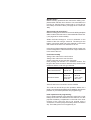
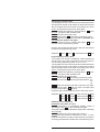
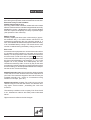
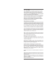
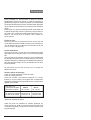
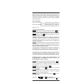
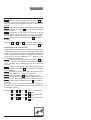
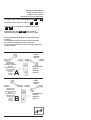
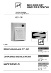
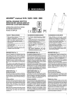
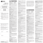
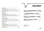
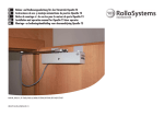
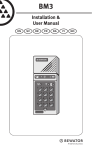
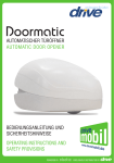
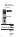
®
SICHERHEIT
UND PRÄZISION
Türöffner-Systeme
Türsteuerungs-Systeme
D 00082
BEDIENUNGS-ANLEITUNG
deutsch
Seite 2
Codeschloß
495-10 / 495-11
OPERATING INSTRUCTIONS
english
Page 7
Code lock
495-10 / 495-11
MODE D'EMPLOI
Page 12
ISTRUZIONI PER L'USO
Pag. 17
français
Serrure
à combinaison
digitale
495-10 / 495-11
italiano
serratura
a combinazione
digitale
495-10 / 495-11
Lieber effeff- Kunde,
wir beglückwünschen Sie zu Ihrem Codeschloß und
danken Ihnen für das Vertrauen, das Sie mit Ihrer Wahl
dem Fabrikat effeff Fritz Fuss entgegenbringen. Wir sind
überzeugt, daß dieses Codeschloß Ihre Erwartungen
erfüllen wird.
Bitte lesen Sie unbedingt vor der Montage bzw. Inbetriebnahme die allgemeinen Hinweise, damit Sie sich mit der
Handhabung des effeff-Codeschlosses vertraut machen
können. Richtige Handhabung und sachgemäße Pflege
sind die Voraussetzung für die hohe Lebensdauer und
ständige Betriebsbereitschaft des Gerätes.
Vorbereitung für die Codeschloßmontage
Da die Länge des Schließzylinders im vorhandenen Türschloß für diesen Codeschloßbeschlag nicht mehr ausreicht, muß in der ersten Umbauphase zunächst ein passender Schließzylinder eingebaut werden. Um die Schließzylinderlänge zu bestimmen, haben wir auf Seite 23 eine
Hilfsskizze abgebildet. Diese Schließzylinder (nicht im Lieferumfang enthalten), lassen sich durch den örtlichen Fachhandel besorgen.
Der Codeschloß-Drückervierkant ist für Standard-Türschlösser mit einer Türdrückernuß von 8 mm vorgesehen. Für die
Türdrückernuß-Maße 8,5 mm und 9 mm liegen dem Montage-Zubehör spezielle Reduzierungshülsen bei.
Umrüstung an bestehenden Türen
Der Codeschloßbeschlag ist nur an Türen montierbar, deren Schlösser ein Dornmaß von mindestens 55 mm aufweisen (Seite 24).
Vorhandene Beschlägegarnitur, Drückervierkant und Zylinder ab- bzw. ausbauen. Neuen Schließzylinder ausmessen
und einbauen (Skizze Seite 23).
Montage an neuen Türen
Standard-Türschloß mit einem Entfernungsmaß von 72 mm
und einem Dornmaß nicht unter 55 mm einbauen. Lauten
die Bestellangaben über ein anderes Entfernungsmaß, so
liegen dem Montagezubehör entsprechende Zylinderplatten
bei.
Neuen Schließzylinder ausmessen und einbauen.
Das Codeschloß wird zunächst auf der, der endgültigen
Montageseite gegenüberliegenden Türblattseite, aufgesteckt (Innenseite).
Bohrschablone an der Außenseite der Tür aufsetzen und
durch Zylinder und Drückervierkant ausrichten. Eine weitere Fixiermöglichkeit ist das Ausrichten durch die auf der
Schablone aufgedruckte Dornmaßeinteilung. Hierbei wird
bei dem durch das eingebaute Schloß vorgegebenen Dornmaß die entsprechende Dornmaßeinteilung auf der Scha2
deutsch
blone abgeschnitten. Dadurch kann die Schablone exakt
auf der Tür ausgerichtet und mit Klebestreifen befestigt
werden. Bei überfälzten Türen muß die Breite des Überschlages beachtet werden.
Holztüren
Bohrpunkte markieren und danach Bohrschablone und
Codeschloß von der Tür entfernen. Direktes Durchbohren
der Tür mittels Holzbohrer Ø 10 mm für Codeschloßbefestigungsschrauben M 5 und Ø 16 mm für das Batterieanschlußkabel (Seite 25).
Metalltüren
Bohrpunkte markieren und danach Bohrschablone und
Codeschloß von der Tür entfernen. Direktes Durchbohren
der Tür mittels Metallbohrer Ø 6 mm (lange Metallbohrer
verwenden, Seite 26).
Mit Aufschälbohrer an der Außenseite der Tür Codeschloßbefestigungsbohrungen auf Ø 10 mm aufweiten. Die
Bohrung für das Batterieanschlußkabel muß an der Türinnenseite sowie an der Türaußenseite auf Ø 16 mm aufgeweitet werden.
Bei Blechtüren dürfen die Verbindungsschrauben M 5 nicht
zu fest angezogen werden, da sich sonst die Tür im Schloßbereich verformen kann.
Fertigmontage
Aufsetzen des Codeschloß-Außenbeschlages
Aufsetzen des Codeschloß-Innenbeschlages
Verschrauben der Codeschloßbeschläge:
Jeder Verpackungseinheit liegen 4 x 2 Codeschloß-Beschlägeschrauben bei. Die Länge der Befestigungsschrauben orientiert sich nach der Türblattstärke und nach
dem bestellten Codeschloß-Typ.
Codeschloß Best.Nr. 495-10
Türblattstärken
38-50 mm
495-11
50-70 mm
Beschlag oben
Beschlag unten
2 St.M 5x80
2 St.M 5x65
2 St.M 5x55
2 St.M 5x45
Aufstecken und Verschrauben der Türdrücker
Bevor die beiliegenden 4 Kunststoffabdeckhüllen für die
Codeschloß-Montagebohrungen aufgesteckt werden, sollte das Codeschloß in Betrieb genommen werden (siehe
Inbetriebnahme und Programmierung).
Inbetriebnahme und Programmierung
Vor der Erstinbetriebnahme des elektrischen Codeschlosses
muß ein 9 Volt Batterieblock in das Codeschloß eingesetzt
werden. Hierzu muß das Batteriefach seitlich am Innen3
schild des Codeschlosses mit einem Schraubendreher geöffnet werden, um die Batterie auf den Anschlußclip zu
stecken. Der Batterieblock ist nicht im Lieferumfang des
Codeschlosses enthalten.
Batterien die zur Auswahl stehen:
9 Volt Lithium-Batterieblock
(Betriebszeit ca. 2 Jahre,
bei täglich ca. 15 Betätigungen)
9 Volt Standard-Batterieblock (Betriebszeit ca. 1 Jahr,
bei täglich ca. 15 Betätigungen)
9 Volt Akku-Block
Funktionsprüfung
Einschalten der Betriebsbereitschaft durch Betätigung der Taste E auf der Folientastatur.
Die grüne LED-Anzeige blinkt zweimal kurz auf als Eingabebereitschaftsanzeige.
Initialisierungscode O eingeben (werkseitige
Grundeinstellung, auch nach Geräte-Reset).
Die Tür bzw. der Türdrücker wird für 3 Sek. zur
Betätigung (zum Öffnen der Tür) freigegeben. Während der
Türentriegelungszeit kann der Türdrücker nur einmal betätigt werden. Ist die Türentriegelungszeit von 3 Sek. abgelaufen, ohne daß die Tür geöffnet wurde, so ist der Türdrücker
wieder verriegelt.
Sollte das Codeschloß nach der Programmierung
oder dem Batteriewechsel nicht ordnungsgemäß funktionieren, so muß der Batterieclip nochmals kurzzeitig von der
Batterie abgezogen werden (kurzzeitige Trennung der
Stromversorgung). Führt dies nicht zum Erfolg, siehe unter
Störung-Reset.
Programmierung mit Eingabezeitlimit
Bei der Programmierung ist unbedingt darauf zu achten,
daß nach jeder Betätigung einer Taste auf der Folientastatur nicht länger als 5 Sek. verweilt werden darf.
Erstprogrammierung des Änderungscodes bzw. Neufestlegung des Änderungscodes nach einem Reset
Einschalten der Betriebsbereitschaft durch Betätigung der Taste E auf der Folientastatur. Die grüne LEDAnzeige blinkt zweimal kurz auf als Eingabebereitschaftsanzeige.
Initialisierungscode O eingeben.
Durch Drücken der Taste P Programmiermodus
einschalten.
Gewünschten Änderungscode über die Folientastatur eingeben. Zur Auswahl steht eine beliebige Codezahl von mind. 2 bis max. 6 Codeziffern.
Durch Drücken der Taste P Eingabe bestätigen.
Beispiel: E O P 1234 P = Änderungscode E 1234
4
deutsch
Neufestlegung des Änderungscodes
Einschalten der Betriebsbereitschaft durch Betätigung der Taste E auf der Folientastatur.
Die grüne LED-Anzeige blinkt zweimal kurz auf als Eingabebereitschaftsanzeige.
Aktuellen Änderungscode eingeben.
Durch Drücken der Taste P Programmiermodus
einschalten.
Gewünschten neuen Änderungscode über die
Folientastatur eingeben. Zur Auswahl steht eine beliebige
Codezahl von min. 2 bis max. 6 Codeziffern.
Durch Drücken der Taste P Eingabe bestätigen.
Beispiel: E 1234 P 4321 P = neuer Änderungscode
E 4321
Programmierung der Benutzercode
Zur Bedienung des Codeschlosses stehen 3 freiprogrammierbare Benutzercodes zur Verfügung. Die Festlegung erfolgt
durch die Plazierungsangabe 1, 2 oder 3 ( sehen Sie hierzu
unser Beispiel).
Die 1. Codeziffer der zu programmierenden Benutzercodes
darf auf keinen Fall mit der 1.Codeziffer des Änderungscodes
übereinstimmend programmiert werden.
Einschalten der Betriebsbereitschaft durch Betätigung der Taste E auf der Folientastatur. Die grüne LEDAnzeige blinkt zweimal kurz auf als Eingabebereitschaftsanzeige.
Aktuellen Änderungscode eingeben.
Durch Drücken der Taste P Programmiermodus
einschalten.
Gewünschte Plazierung des Benutzercodes eingeben (Ziffer 1 = Erster Benutzercode).
Durch Drücken der Taste P Eingabe bestätigen.
Gewünschten Benutzercode eingeben. Zur Auswahl steht eine beliebige Codezahl bis max. 6 Codeziffern.
Durch Drücken der Taste P Eingabe bestätigen.
Die Programmierung eines evtl. zweiten oder dritten
Benutzercodes muß nach dem vorgenannten Prinzip erfolgen (sehen Sie hierzu unser Beispiel).
Beisp.: E 4321 P 1 P 78493 P = 1. Benutzercode E 78493
E 4321 P 2 P 539 P = 2. Benutzercode E 539
E 4321 P 3 P 7431 P = 3. Benutzercode E 7431
Bedienung des Codeschlosses (max. Eingabezeit 13 Sek.)
Einschalten der Betriebsbereitschaft durch Betätigung
der Taste E auf der Folientastatur. Die grüne LED-Anzeige blinkt
zweimal kurz auf als Eingabebereitschaftsanzeige.
Aktuellen Benutzercode eingeben (eine der drei programmierten Benutzercodes).
Die Tür bzw. der Türdrücker wird für 3 Sek. zur Betätigung (zum Öffnen der Tür) freigegeben. Während der Türentriegelungszeit kann der Türdrücker nur einmal betätigt werden. Ist
die Türentriegelungszeit von 3 Sek. abgelaufen, ohne daß die Tür
geöffnet wurde, so ist der Türdrücker wieder verriegelt.
5
Falscheingaben von Codezahlen - Sperrzeit 13 Sek.
Wird eine falsche Codezahl eingegeben, erfolgt keine Freigabe der Tür. Desweiteren wird die Folientastatur für 13
Sek. elektronisch gesperrt (Sperrzeit). Erst nach Ablauf
dieser Sperrzeit ist wieder eine komplett neue Eingabe
möglich (siehe Bedienung des Codeschlosses).
Batteriewechsel
Bei weitgehend verbrauchter Batteriekapazität (noch ca. 50
Betätigungen möglich), blinkt während der Türentriegelungszeit von 3 Sek. eine rote LED-Anzeige auf der
Folientastatur auf. Diese Anzeige weist den Nutzer/Betreiber auf die Notwendigkeit eines umgehenden Batteriewechsels hin. Die gespeicherte aktuelle Codezahl bleibt
während des Batteriewechselvorgangs erhalten.
Störung-Reset
Für den Gerätestörfall oder bei Verlust der Codezahl besteht die Möglichkeit eines Geräte-Resets (beachten Sie
Seite 22). Hierzu muß der äußere Codeschloßbeschlag
abmontiert werden, um auf der Codeschloß-Rückseite
(Außenschild) einen Reset-Taster bedienen zu können.
Zunächst muß (bei angeschlossener Batterie) auf der Tastatur die E Taste gedrückt werden und anschließend
innerhalb von 13 Sek. der vorgenannte Reset-Taster. Nach
diesem Vorgang muß das Codeschloß wieder montiert
werden. Durch diesen Reset-Vorgang ist das Codeschloß
wieder auf die werkseitige Grundeinstellung programmiert.
Die weitere Bedienung wird im Abschnitt Funktionsprüfung
erklärt.
Bitte beachten Sie: Während der Codeeingabe
darf der Türdrücker des Codeschlosses nicht betätigt werden. Die Folientastatur des Codeschlosses darf ausschließlich nur manuell betätigt werden (auf keinen Fall mit Gegenständen wie z.B. Schlüssel, Schreibstiften etc.)
Pflegehinweise: Das Codeschloß darf nur mit
einem feuchten Lappen und mit nichtkratzenden, milden
Putzmitteln gereinigt werden. Vermeiden Sie das Eindringen von Feuchtigkeit in die Codeschloßbeschläge.
Für das hier beschriebene effeff-Produkt
gelten die Garantiebedingungen der
Firma Fritz Fuss GmbH & Co., Albstadt
Technische Änderungen vorbehalten.
6
english
Dear effeff client,
May we congratulate you on your code lock and thank you
for the trust you have placed in effeff Fritz Fuss in selecting
this brand. We are convinced that this code lock will meet
your expectations. It is essential that you read the general
instructions prior to initial operation, in order that you are
able to familiarize yourself with the handling of the effeff
code lock. Correct handling and proper care are prerequisites
for a long service life and the constant operational readiness
of the equipment.
Preparations prior to fitting the code lock
As the length of the lock cylinder in the existing door lock is
no longer sufficient for the code lock’s hardware, the first
conversion step must be to install a suitable lock cylinder. As
an aid there is a sketch on page 23 for the purpose of determining the lock cylinder’s length. These lock cylinders
(not supplied by us) are obtainable from your local lock
smith shop.
The code lock’s spindle for the handle is envisaged for
standard door locks with a follower width of 8 mm. Special
reduction bushes are enclosed with the installation
accessories for the follower width of 8.5 mm and 9 mm.
In order to fit two cylinder plates to the code lock 8 countersunk head screws M4 x 8 mm are included with the installation
accessories.
Conversion of existing doors
The code lock hardware is only fittable to doors whose locks
have a backset of at least 55 mm (see page 24 for further
details).
Remove the existing hardware set, handle and cylinder.
Gauge and fit the new lock cylinders (see page 23).
Fitting to new doors
Fit a standard door lock with CTC-distance (center to
center) of 72 mm and a backset of not less then 55 mm. If
the ordering data specify a different CTC-distance,
appropriate cylinder plates are included with the installation
accessories.
Gauge and fit the new lock cylinder ( see sketch).
Initially place the keyboard furniture on the inside of the door
and place the drilling template on the outside of the door, in
order to align it by using the spindle of the handle and
cylinder holes. Another method of fixture is alignment using
the backset chart printed on the template. Using this select
the correct backset chart is suitable for your lock. Then cut
the template to this line. By doing this, the template is
alignable precisely with the door and lock
and fixable by means of adhesive tapes
( see sketch). Should the doors be
rebated doors the width of the rebate
or shiplap has to be taken into
consideration.
7
Wooden doors
Mark the drilling points and then remove the drilling template and the code lock from the door. Use wood drills of 10
mm dia. for the M 5 fixture screws and of 16 mm dia. for
the battery connection cable ( see page 25 for further details).
Sheet metal and metal doors
Mark the drilling points and then remove the drilling template
and the code lock from the door. Use metal drills of 6 mm dia.
( see page 26 for further details).
Widen the fixture borings to 10 mm in diameter on the
outside of the door using a centre bit. The boring for the
battery connection cable has to be widened on the inside
and outside of the door to a diameter of 16 mm.
In the case of sheet metal doors the M 5 joining screws may
not be overtightened, otherwise the door may be deformed
in the area of the lock.
Finished assembly
Fitting of the code lock’s outer furniture
Fitting of the code lock’s inner furniture
Screw connection of the code lock furnitures:
Each packing unit includes 4 x 2 hardware screws. The
length of the fixture screws is determined by the door leaf
thickness and the code lock type ordered.
Code lock ordering off
door leaf thickness
495-10
38-50 mm
495-11
50-70 mm
Furniture top
2 pcs. each
M 5 x 55
2pcs. each
M 5x 45
2 pcs. each
M 5x 80
2 pcs. each
M 5 x 65
Furniture bottom
Press-fit and screw connection of door handles
The code lock should be put into operation before the 4
plastic cover bushes supplied for the installation borings are
pressed on (see initial operation and programming).
Initial operation and programming
Prior to initial operation of the electronic code lock a 9 volt
battery block has to be inserted into the code lock. For this
purpose the battery compartment on the side of the inner
furniture of the code lock has to be opened using a
screwdriver, in order to plug in the battery via the connection
clip. The battery block is not supplied by us.
8
english
Batteries to choose from
9 volt lithium battery block (operating life approx. 2 year)
9 volt standard battery block ( operating life approx. 1 year)
9 volt accumulator block
Functional testing
Switching-on of operational standby mode by
actuating the key E on the membrane keypad.
The green LED indicator will flash on briefly twice, indicating
entry standby.
Enter code number O ( original ex-works setting,
also after an equipment reset).
The door handle is released for actuation for 3
seconds (in order to open the door). During the door
unlocking period the door handle can be actuated only
once.
If the door unlocking period of 3 seconds has expired without
the door having been opened, the door handle is relocked
If the code lock does not function properly subsequent to programming or a battery change, the battery clip
has to be disconnected from the battery again for a short
while (brief interruption of the power supply).
If this proves to be unsuccessful, see Error reset.
Programming of the code number ( maximum entry time 13
secs.)
Programming with time limit
Please pay attention when programming numbers into the
system only 5 sec. is allowed between pressing (entering)
each digit. Failure to observe this will mean that you have
to start your programming again from the beginning.
Initial programming of the master code or reinitaline
master code after a reset.
Switching-on of operational standby mode by
actuating the key E on the membrane keypad.
The green LED indicator will flash on briefly twice, indicating
entry standby.
Enter initialisation code O .
Switch on programming mode
by pressing the key P .
Enter the mastercode (programming code) with a
minimum of 2 and maximum number of 6 digits.
Confirm entry by pressing the key P and switch off
programming mode.
Example: E O P 1234 P = mastercode E 1234
9
Changing the master code
The first digit of a user code must never be identical with the
first digit of the master code! Failure to observe this means
that a complete reset of all codes is necessary see "Error
reset". All programming has to be done again.
Actuate the system by pressing button E on the
key pad. The green LED will flash twice.
Enter the old master code.
Press button P to actuate programming mode.
Enter the new master code with a minimum of 2
and maximum number of 6 digits.
Confirm entry by pressing the button P . This
switches off the programming mode.
Entering the mastercode also opens the door and allows
access to the programming mode.
Example: E 1234 P 4321 P = new mastercode E 4321
Programming of user codes
The system can accept 3 additional codes besides the
master. Each user code is programmed into the system in
one of these programming slots 1P, 2 P or, 3 P.
The first digit of a user code must never be identical with the
first digit of the master code! Failure to observe this means
that a complete reset of all codes is necessary see "Error
reset". All programming has to be done again.
Actuate the system by pressing button E on the
key pad. The green LED will flash twice.
Enter the old master code.
Press button P to actuate programming mode.
To enter the programming slot press either 1P…
2 P…
3 P…
Enter the desired code with a maximum of 6 digits.
Press button P and the code is accepted and
programming mode is switched off.
Programming of all the codes is done in the same manor.
Examples: E 4321 P 1 P 78493 P = First usercode E 78493
E 4321 P 2 P 539 P = Second usercodeE 539
E 4321 P 3 P 7431 P = Third usercode E 7431
Operation of the code lock
(maximum entry time 13 secs.)
Switching-on of operational standby mode by
actuating the key E on the membrane keypad.
Thee green LED indicator will flash on briefly twice, indicating
entry standby.
Entering one of the valid code numbers.
The door handle is released for 3 secs. For the
purpose of actuation (in order to open the door). During the
unlocking period the door handle can be actuated only once.
10
english
If the door unlocking time of 3 secs. has expired without the
door having been opened, the door handle is then relocked.
Erroneous entry of code numbers
disable time period 13 secs.
If a wrong code number is entered, release of the door is not
effected. Furthermore the membrane keypad is electronically
disabled for 13 secs. ( disable time). Only once this disable
time has expired a completely new entry is possible again
(see operation of the code lock).
Battery change
If battery capacity has been more or less used up ( approx.
50 actuations left), a red LED indicator will blink on the
membrane keypad during the door unlocking period of 3
secs. This indicator advises the user/operator of the necessity
of an immediate battery change. The stored current code
number is retained during the battery change procedure.
Error reset
In the event of an equipment error or loss of the code number
it is possible to reset equipment ( see page 22 for further
details). For this purpose the outer code lock furniture has
to be removed, in order to be able to operate the reset key
on the rear side of the code lock (outer plate). In order to do
this, first of all (with battery connected) the E key on the
keypad has to be pressed and subsequently the aforementioned reset key within 13 secs. By way of this reset
procedure the code lock is again programmed to the original
ex-works setting. For further operation details on this subject
see the section Functional testing.
Please take note: During operation the door handle
of the code lock’s outer furniture must not be subjected to a
prior load. The membrane keypad of the code lock may be
actuated manually only ( under no circumstances using
articles such as keys, pens etc.).
Instructions on care: The code lock may only be
cleaned using a moist cloth with a mild, non-abrasive cleaning agent. Avoid moisture penetrating the code lock
furnitures.
The warranty conditions of the company Fritz Fuss GmbH
& Co., Albstadt are valid for the effeff product described
above.
Right reserved to effect technical changes.
11
Cher client effeff,
vous venez de faire l´acquisition d´une serrure à combinaison digitale et nous vous en félicitons. Nous vous remercions de la confiance que vous nous témoignez en
choisissant un produit effeff Fritz Fuss. Nous ne doutons
pas qu´il vous donnera entière satisfaction.
Veuillez lire attentivement les remarques d´ordre général
avant de mettre le matériel en service. Vous apprendrez
ainsi à le connaître et son utilisation en sera facilitée.
Sachez qu´une manipulation correcte et un entretien
approprié sont des conditions essentielles pour garantir
le parfait fonctionnement du matériel.
Préparatifs pour le montage
La longueur du barillet en place dans la serrure n'étant pas
suffisante pour une serrure à combinaison digitale, il convient
tout d‘abord de remplacer le barillet. Pour définir la longueur
qui convient le mieux, reportez vous au croquis de la page
23. Ces barillets ne sont pas inclus dans la fourniture.
Veuillez en faire l‘acquisition dans un magasin spécialisé.
L‘axe de la poignée est prévu pour des serrures standard
avec un fouillot de 8 mm. Toutefois, avec des réducteurs
adéquats, il peut être monté sur des serrures avec dont le
fouillot est de 8,5 mm ou de 9,5 mm.
Mise en place de la plaquette de fixation dans la rosette à
l‘aide de 8 vis noyées M 4 x 8 mm. Deux plaques de fixation
sont comprises dans la fourniture.
Montage sur portes déjà en place:
Le système ne peut être monté que sur des portes dont
l´entraxe barillet-tétière est d´au moins 55 mm (voir le
croquis à la page 24).
Démonter les rosettes en place, l´axe de la poignée et le
barillet. Prendre les mesures du nouveau barillet et le mettre
en place (voir le croquis à la page 23).
Première phase du montage sur portes neuves:
Monter une serrure standard avec un entraxe fouillot-barillet
de 72 mm et un entraxe barillet-tétière d‘au moins 55 mm.
Si la commande a été fait pour un entraxe fouillot-barillet
différent de 72 mm, deux plaquettes de fixation seront
comprises dans la fourniture.
Prendre les mesures du nouveau barillet et le mettre en
place.
Appliquer tout d‘abord la rosette portant le clavier sur la face
intérieure du battant de la porte (pas sur le côté où il sera fixé
définitivement).
Appliquer le gabarit de percage sur la face extérieure du
battant et le dégauchir en mettant en place le barillet et
l´axe de la poignée.
Marquer les endroits à percer.
12
français
Autre possibilité: La serrure étant en place et l‘entraxe
barillet-tétière étant donc donné, il suffit de découper le
gabarit de percage sur la ligne de référence correspondant
à l‘entraxe barillet-tétière en place. Ensuite utiliser le gabarit
de percage ainsi dimensionné pour marquer les endroits à
percer.
Avant de percer, retirer la rosette portant le clavier ainsi que
le gabarit de percage. Selon le type de la porte (en bois ou
en métal), tenir compte des observations faites plus loin.
Dans le cas d‘une porte à feuillure, tenir compte du
recouvrement.
Portes en bois:
Percer la porte avec une mèche à bois de 10 mm pour les
vis de fixation M 5 de la rosette à clavier et une mèche de 16
mm de diamètre pour le câble de branchement de la pile
(voir le croquis à la page 25).
Portes métalliques:
Percer la porte avec un foret de 6 mm de diamètre (utiliser
de préférance une longueur mèche, voir le croquis à la page
26).
Avec une mèche à chanfrein, élargir à 10 mm de diamètre
les alésages de fixation pour la rosette à clavier, sur la face
extérieur du battant. L‘alésage pour le câble de branchement
de la pile doit être élargi à 16 mm de diamètre sur les deux
faces du battant.
Ne pas serrer trop fort les vis M 5 pour ne risquer de
déformer la porte.
Dernière phase du montage
Poser la rosette extérieure portant le clavier.
Poser la rosette intérieure.
Visser les rosettes: La fourniture comprend 2 x 4 vis de
fixation (4 vis par rosette). La longueur des vis dépend de
l‘épaisseur du battant et du type de la serrure à combinaison
digitale commandée.
Réf.Serrure à
combinason digitale:
Epaisseur de porte
495-10
38 - 50 mm
En haut de la rosette 2 vis M 5 x 55
En bas de la rosette 2 vis M 5 x 45
495-11
50 - 70 mm
2 vis M 5 x 80
2 vis M 5 x 65
Mettre les poignées en place.
Avant de poser les pastilles en matière plastique qui
recouvrent les vis, tester le fonctionnement de la serrure à
combinaison digitale (se reporter au mode d‘emploi et de
programmation).
13
Mode d‘emploi et de programmation
Mettre en place une pile de 9 V dans le logement prévu à cet
effet sur le côté de la rosette intérieure qui est à ouvrir à
l‘aide d‘un tournevis. Presser sur la pile pour l‘engager
correctement sur le bornier à clip. La pile n‘est pas comprise
dans la fourniture.
Piles utilisables:
Pile de 9 V au lithium
(durée de vie: 2 ans environ, à
raison d'environ 15 sollicitations par jour)
Pile de 9 V standard
(durée de vie: 1 an environ, à
raison d'environ 15 sollicitations par jour)
Bloc accu 9 V
Test de fonctionnement
Mise en service par pression de la touche E sur le
clavier. La LED verte clignote brièvement deux fois de suite,
signalant que le système est prêt à recevoir des données.
Taper le code O (Etat de base réglé à l‘usine et
retrouvé après un Reset)
La porte est libérée pour une durée d‘environ 3
secondes. Pendant cette durée, la poignée ne peut être
actionnée qu‘une seule fois. Si les 3 secondes se sont
écoulées sans que la porte ait été ouverte, la poignée se
retrouve verrouillée.
Si le fonctionnement n‘est pas assuré après la
programmation ou après un changement de pile, sortir la
pile puis la remettre en place dans le bornier à clip (interruption
brève de l‘alimentation électrique).
Si cette mesure ne suffit pas pour remettre le système en
fonctionnement, il faudra faire un Reset (se reporter à
l‘explication donnée pour le Reset en fin de document).
Programmation avec limitation du temps d'intervention
S'assurer pendant la procédure de programmation, qu'il ne
s'écoule pas plus de 5 secondes après la frappe d'une touche.
Première mise en place du code d'accès à la
programmation ou redéfinition du code d'accès à la
programmation après un Reset.
Mise en service par pression de la touche E sur
le clavier. La LED verte clignote brièvement deux fois de
suite, signalant que le système est prêt à recevoir des
données.
Taper le code d'initialisation O
Presser la touche P pour passer en mode de
programmation.
Composer sur le clavier le code d'accès à la
programmation qui a été choisi: au choix un nombre
quelconque à 6 chiffres maximum.
Presser une nouvelle fois la touche P pour confirmer la saisie.
Exemple:
14
E O P 1234 P = code d'accès
à la programmation E 1234
français
Redéfinition du code d'accès à la programmation
Mise en service par pression de la touche E sur
le clavier. La LED verte clignote brièvement deux fois de
suite, signalant que le système est prêt à recevoir des
données.
Taper le code d'accès à la programmation actuel.
Presser la touche P pour passer en mode de
programmation.
Composer sur le clavier le nouveau code de
programmation qui a été choisi: au choix un nombre
quelconque de 2 chiffres minimum à 6 chiffres maximum.
Presser une nouvelle fois la touche P pour confirmer
la saisie.
Exemple: E 1234 P 4321 P = nouveau code d'accès à
la programmation E 4321
Programmation du code d'accès
Il est possible de programmer trois différents codes d'accès
qui permettent d'ouvrir la porte. Cette programmation des
codes 1, 2 et 3 est à faire selon les explications suivantes.
Veiller attentivement à ce que le 1er chiffre du code d'accès
de la porte ne soit pas identique au 1er chiffre du code
d'accès à la programmation.
Mise en service par pression de la touche E sur
le clavier. La LED verte clignote brièvement deux fois de
suite, signalant que le système est prêt à recevoir des
données.
Taper le code d'accès à la programmation actuel.
Presser la touche P pour passer en mode de
programmation.
Préciser sur le clavier le numéro du code d'accès à
programmer (chiffre 1 = premier code d'accès).
Presser la touche P pour confirmer le choix.
Composer alors sur le clavier le code d'accès qui a
été choisi: un nombre quelconque de 6 chiffres maximum.
Presser une nouvelle fois la touche P pour confirmer
la saisie.
Pour programmer le second et le troisième codes d'accès,
procéder selon le principe décrit ci-devant et conformément
à l'exemple ci-après.
Exemple: E 4321 P 1 P 78493 P = premier code d'accès
E 78493
E 4321 P 2 P 539 P = second code d'accès
E 539
E 4321 P 3 P 7431 P = troisème code d'accès
E 7431
15
Ouverture de la porte
(durée max. pour composer le code: 13 secondes)
Mise en service par pression de la touche E sur
le clavier. La LED verte clignote brièvement deux fois de
suite, signalant que le système est prêt à recevoir des
données.
Taper le code d'accès en vigueur (l'un des trois
codes programmés).
La porte est libérée pour environ 3 secondes.
Pendant cette durée, la poignée ne peut être actionnée
qu‘une seule fois. Si les 3 secondes sont écoulées sans que
la porte soit ouverte, la poignée est reverrouillée
automatiquement.
Composition d'un faux code:
clavier bloqué pendant 13 secondes
Si l‘on tape un faux code, la porte ne sera pas libérée et le
clavier sera bloqué électroniquement pendant 13 secondes.
Après ces 13 secondes, il est de nouveau possible de
renouveler la tentative d'accès (conformément à la procédure
précisée plus haut sous le titre "Ouverture de la porte".
Changement de pile
Lorsque commence à se décharger, une LED rouge clignote
sur le clavier pendant le déverouillage de la gâche. On sait
alors que la capacité de la pile est encore suffisante pour
ouvrir environ 50 fois la porte. Il convient de changer la pile
en temps voulu. Le code en mémoire est conservé pendant
l‘échange de la pile.
Dérangement - Reset
En cas de dérangement ou bien si l‘on a oublié le code, on
peut faire un Reset (cf. page 22 ). A cette fin, démonter le
couvercle externe du boîtier, pour accéder au bouton Reset
sur la face postérieure du boîtier. Presser tout d'abord la
touche E (batterie raccordée), puis dans les 13 secondes
qui suivent presser la touche Reset. Dès que cette opération
est terminée, il convient de remettre le couvercle du boîtier
en place. Le Reset réinitialise la serrure à combinaison
digitale, autrement dit la ramène à l'état de programmation
initial (programmation usine). Se reporter au chapitre "Test
de fonctionnement" pour suite à donner.
A observer: Ne pas actionner la poignée de la
porte pendant que l'on compose le code sur le clavier.
Presser les touches uniquement du bout des doigts (en
aucun cas avec une clé, un stylo ou autre objet similaire).
Entretien: Pour nettoyer le clavier, se servir d‘un
chiffon mouillé et d‘un produit de nettoyage non doux. Eviter
tout infiltration d'eau dans le boîtier.
La serrure à combinaison digitale est
garantie selon les conditions
générales effeff.
Sous réserve de modification techniques!
16
italiano
Caro cliente effeff,
Avete fatto indubbiamente un ottima scelta: un sistema di
controllo della porta a tastiera digitale effeff è una
garanzia di qualità e siamo certi ne rimarrete soddisfatti.
Leggete attentamente le istruzioni generali, l’istallazione
e l’uso saranno estremamente facili.
Una buona manutenzione garantisce un perfetto
funzionamento del prodotto.
Consigli per l’istallazione
La lunghezza del cilindro profilato esistente sulla Vs. porta
non sarà sufficiente per piazzare la serratura a codice
digitale. Per definire la lunghezza del cilindro profilato
vedere a pag. 23. L’acquisto di un nuovo cilindro di sicurezza
potrà essere fatto presso un rivenditore specializzato.
L’interasse della maniglia è previsto per serrature standard
Italiane con q.8.
Per un perfetto assemblaggio delle bocchette alle placche,
sono in dotazione 8 viti M 4 x 8 mm.
Istallazione su porte esistenti
Il sistema serratura a codice effeff può essere montato su
porte con entrata minima di 55 mm. Le bocchette vengono
fornite standard in Italia per un interasse di 85 mm.
Smontare le maniglie ed il cilindro esistenti, prendere le
misure per il nuovo cilindro di sicurezza, forare come da
istruzioni a pag. 23/24, montare il nuovo cilindro, applicare
le placche del sistema a codice. La Vs. vecchia serratura è
diventata un sistema di controllo accessi a codice digitale.
Istallazione su porte nuove.
Montare una serratura standard di buona qualità con entrata
minima 55 mm e con un interasse compreso fra 72 e 92 mm.
Nell’ordinare il sistema a codice digitale, precisare la misura
interasse della serratura. In Italia la fornitura standard è per
serrature con interasse mm 85.
Prendere le misure per la lunghezza del cilindro profilato.
Istallare la serratura standard con le consuete dime,
accertandosi dell’esatta foratura dell’interasse quadro
maniglia / cilindro profilato ed entrata cilindro.
Nel caso di porte ricoperte, tener conto dello spessore della
ricopertura.
17
Porte in legno:
Forare con una punta da legno da 10 mm per le viti di
fissaggio da 5 MA e con una punta da 16 mm par il cavo di
collegamento al vano batteria (vedi pag. 25)
Porte metalliche
Forare con una punta per metallo da 6 mm. Con uno
alesatore svasare i fori solo nella parte esterna della porta
fino a 10 mm. Per il foro del cavo batteria, svasare fino a 16
mm su entrambi i lati della porta (vedi pag. 26).
Non serrare fortemente le viti da 5 MA per evitare di
deformare la porta.
Ultima fase di montaggio
Applicare sul lato esterno la placca con tastiera. Applicare
la placca contenente il vano batterie all’interno. Avvitare le
placche con le viti di fissaggio comprese nel set. La lunghezza
delle viti in dotazione dipende dallo spessore porta e in
dipendenza da ciò ordinate l’articolo esatto come da tabella.
Articolo della serratura
a combinazione digitale: 495-10
Spessore porta
38 - 50 mm
Viti parte superiore
della placca
Viti parte inferiore
della placca
495-11
60 - 70 mm
2 pz 5 MA x 55
2 pz 5 MA x 80
2 pz 5 MA x 45
2 pz 5 MA x 65
Inserire e fissare l’impugnatura maniglia.
Prima di appore le coperture in plastica sulle viti di fissaggio,
controllare il corretto funzionamento della serratura a codice
digitale, a porta aperta (vedi istruzioni di programmazione e
d’utilizzo).
Istruzioni di programmazione e di utilizzo
Per l'utilizzo della serratura a codice va usata una pila a 9
Volt. Inserire una pila nel vano batteria apribile tramite un
cacciavite. Premere bene la pila nella sua sede. (La pila non
è compresa nel set)
Pile consigliate:
Pile a 9 V alcaline
(durata di circa 2 anni per una
funzione giornaliera di circa 15 azionamenti)
Pile a 9 V standard
(durata di circa 1 anno per una
funzione giornaliera di circa 15 azionamenti)
Accumulatore a 9 Volt
18
italiano
Prova di funzionamento
Premere il tasto E sulla tastiera. Il LED verde si
illuminerà brevemente due volte di seguito segnalando che
il sistema è pronto a ricevere i comandi
Premere il tasto O (Situazione di partenza in stato
di Reset stabilito in fabbrica)
La porta è apribile per un tempo di circa 3 secondi.
Durante questo tempo la maniglia può essere azionata una
sola volta. Trascorsi i 3 secondi senza che la porta venga
aperta, la maniglia è di nuovo bloccata.
Se dopo la programmazione od il cambio di pila la
serratura non funzionasse perfettamente, togliere la pila e
rimetterla correttamente nella sua sede.
Se questo accorgimento non bastasse per il funzionamento
del sistema bisognerà procedere ad un Reset. (Vedi
spiegazioni relative al Reset della serratura a codice)
Digitazione in tempo limitato
Nella digitazione fare attenzione che, tra la digitazione di un
tasto e l'altro non devono passare più di 5 secondi, altrimenti
si deve rifare l'intero codice.
Prima programmazione del codice master - nuova
determinazione del codice master
Premere il tasto E sulla tastiera. Il LED verde si
illuminerà brevemente due volte di seguito segnalando che
il sistema è pronto a ricevere i comandi.
Premere il tasto O (Situazione di partenza).
Premere il tasto P e inserire il modo di programma.
Digitare sulla tastiera il codice desiderato. Scegliere
qualsiasi numero e formare il codice per un massimo di 6
cifre.
Premere il tasto P e confermare le indicazioni date.
Esempio: E O P 1234 P = E 1234
Nuova determinazione del codice master
Premere il tasto E sulla tastiera. Il LED verde si
illuminerà brevemente due volte di seguito segnalando che
il sistema è pronto a ricevere i comandi.
Inserire il codice attuale.
Premere il tasto P e inserire il modo di programma.
Digitare sulla tastiera il codice desiderato. Scegliere
qualsiasi numero e formare il codice che può avere da un
minimo di 2 a un massimo di 6 cifre.
Premere il tasto P e confermare le indicazioni date.
Esempio: E 1234 P 4321 P = Nuovo codice E 4321
19
Programmazione del codice degli utilizzatori
Per l'utilizzo della serratura a codice ci sono a disposizione
3 codici programmabili. La determinazione si effettua
attraverso l'indicazione dei collocamenti 1, 2 o 3 (vedi nostri
esempi qui sotto).
La 1. cifra del codice utente da programmare non deve
corrispondere in nessun caso alla 1. cifra del codice di
modifica.
Premere il tasto E sulla tastiera. Il LED verde si
illuminerà brevemente due volte di seguito segnalando che
il sistema è pronto a ricevere i comandi.
Inserire il codice attuale.
Premere il tasto P e inserire il modo di programma.
Inserire il collocamento dell'utilizzatore desiderato
(cifra 1 = primo codice del primo utilizzatore).
Premere il tasto P e confermare le indicazioni date.
La programmazione di uno e eventualmente di due o tre
codici degli utilizzatori deve essere eseguito secondo il
principio sopracitato (Vedi nostro esempio qui sotto).
E 4321 P 1 P 78493 P = Primo codice dell'utilizzatore E 78493
E 4321 P 2 P 539 P = Sec. codice dell'utilizzatore E 539
E 4321 P 3 P 7431 P = Terzo codice dell'utilizzatore E 7431
Apertura della porta
Premere il tasto E sulla tastiera. Il LED verde si
illuminerà brevemente due volte di seguito segnalando che
il sistema è pronto a ricevere i comandi
Digitare il nuovo codice appena programmato (uno
dei 3 codici programmati).
La porta è apribile per un tempo di circa 3 secondi.
Durante questo tempo la maniglia può essere azionata una
sola volta. Trascorsi i 3 secondi senza che la porta venga
aperta, la maniglia è di nuovo bloccata.
Imputazione di un codice errato
Se viene digitato un codice falso/errato, la porta non può
essere aperta e la tastiera rimane disabilitata per 13 secondi.
Trascorso questo tempo si può ricomporre il codice.
Cambio della pila
Quando la pila si sta scaricando, il LED rosso lampeggia
sulla tastiera durante l’apertura. Conviene predisporre il
cambio della pila al più presto. Il LED rosso inizia a
lampeggiare quando si ha ancora potenza per effettuare
circa 50 aperture.
20
italiano
Reset
In caso di cancellazione o dimenticanza del codice segreto,
si può fare una operazione di Reset del sistema. La placca
con la tastiera deve essere rimossa per poter premere il
tasto Reset con un oggetto appuntito non metallico (vedi fig.
a pag. 22). Dopo l’operazione di reset proseguire con
Programmazione codice d'entrata.
Nota bene - Quando si digita il codice d'entrata non
premere sulla maniglia. Assolutamente non digitare il codice
con chiave, penne od altri oggetti similari.
Manutenzione - Per la pulizia esteriore della tastiera
usare un panno morbido . Non usare prodotti chimici abrasivi
o troppo fluidi che possono penetrare all'interno.
La serratura a codice digitale è garantita secondo le norme
generali di garanzia effeff.
Il prodotto può essere modificato secondo le esigenze
tecniche.
21
LED-Anzeigen
LED indications
signaux LED
Indicatori LED
Folientastatur
foil keyboard
clavier à effleurement
Tastiera
Rosette
rosette
rosace
Bocchetta
Batteriefach
battery space
espace pour batterie
Vano batterie
Türschloß
door lock
serrure de porte
Serratura
Reset-Taster
reset push-button
bouton-poussoir reset
Tasto Reset
Türdrückernuß
follower for handle
fouillot
Quadro maniglia
Rosette
rosette
rosace
Bocchetta
22
english
français
deutsch italiano
Beschlagdicke außen
brace thickness
outside
épaisseur de
ferrure extérieur
Spessore placca esterna
13
Türdicke
door thickness
épaisseur de porte
Spessore porta
Beschlagdicke innen
brace thickness
inside
épaisseur de
ferrure intérieur
Spessore placca
interna
13
Beispiel Holztür
e.g.wooden door
p.e.porte de bois
Porta in legno
Profilzylinder
profile cylinder
barillet profilé
Cilindro
sagomato
99
Beschlagbreite
brace width
largeur de ferrure
Larghezza placca
Schloßlage
lock position
position de serrure
Serratura
Stulpschraube
faceplate screw
vis de fétière
Frontale serratura
A
B
Außenseite
outside
extérieur
Esterno
Innenseite
inside
intérieur
Interno
A
B
Profilzylinder
profile cylinder
barillet profilé
Cilindro sagomato
23
+ ++
8 mm
Entfernungsmaß
CTC-distance (center to center)
entraxe
Interasse mm 85
72 mm
Drückernuß
follower for handle
fouillot
Quadro maniglia
55 mm
Dornmaß
backset
entrée
Entrata
+ +
Profilzylinder
profile cylinder
barillet profilé
Cilindro sagomato
Stumpftür
plain door
porte affleurante
Porta a filo
Falztür
rebated door
porte à recouvrement
Porta con battuta
24
Montage bei Holztüren
Fitting into wood doors
Fixation dans le bois
Istallazione su porte in legno
+ ++
A
A
B
A
A
+ +
A
Holzbohrer Ø 10 mm
wood borer Ø 10 mm
foret à bois Ø 10 mm
Punta da legno Ø 10 mm
B
Holzbohrer Ø 16 mm
wood borer Ø 16 mm
foret à bois Ø 16 mm
Punta da legno Ø 16 mm
25
+ ++
A/B
A/B
A/C
A/B
A/B
+ +
A
Metallbohrer
metal borer
foret à metaux
Punta a metallo
Ø 6 mm
Ø 6 mm
Ø 6 mm
Ø 6 mm
B
aufschälen bis
bore open up to
alésez jusqu'a
Svasare fino a
Ø 10 mm
Ø 10 mm
Ø 10 mm
Ø 10 mm
C
aufschälen bis
bore open up
alésez jusqu'a
Svasare fino a
26
Ø 16 mm
Ø 16 mm
Ø 16 mm
Ø 16 mm
Montage bei Metalltüren
Fitting into metal doors
Fixation dans le métal
Istallazione su porte metalliche
Festlegung der Codeschloß-Ausführung A oder B
Definition of the code lock version A or B
Definition de la serrure de codage selon version
A ou B
Definizione del tipo A o B della serratura
dipendente dalla mano della porta come segue
Die Codetastatur wird immer auf der Außenseite
montiert.
The keypad is always mounted on the front side
Le clavier est toujours monté en extérieur
La parte con tastiera deve essere sempre applicata
sul lato esterno
Innenbereich
inside
intérieur
interno
TüröffnungsMöglichkeiten
opening possibilities
of a door
possibilités de baie
Tipo di apertura
Ausführung
version
vérsion
versione
A
Außenbereich
outside
extérieur
esterno
Innenbereich
inside
intérieur
interno
TüröffnungsMöglichkeiten
opening possibilities
of a door
possibilités de baie
Tipo di apertura
Ausführung
version
vérsion
versione
B
Außenbereich
outside
extérieur
esterno
27
The company
effeff - ein starkes und
technologie-orientiertes Unternehmen hat ein unverwechselbares, in über 50jähriger Firmengeschichte
gewachsenes Profil. Das
Unternehmen, das heute
über 800 Mitarbeiter beschäftigt, gilt in seinen Märkten als ein Haus, das Konzeptionen prägt und Richtungen weist. Strenge Orientierung an Zukunfts-Technologien und die konsequente
Realisierung technologischer Spitzenlösungen haben effeff zu seiner qualifizierten Marktposition
geführt.
effeff - a dynamic, technologically oriented enterprise
whose unmistakable profile
is the culmination of over 50
years of successful company
history. Today employing a
staff of over 800, the company enjoys a reputation in
the markets it serves for progressive technological development and trailblaizing
concepts. It is dedication to
the technologies of the future
and a consistent record in
realizing outstanding solutions which have placed
effeff in its qualified market
position.
L´entreprise effeff
L'IMPRESA
Une entreprise à très fort
développement technologique qui bénéficie d´une expérience de plus de 50 ans,
ce qui lui assure une réputation imcomparable.
Plus de 800 ouvriers et
cadres s´emploient à faire la
réputation de la marque et à
respecter les orientations,
garanties de leur réussite
dans le domaine de la
technologie de pointe et
d´avenir.
effeff un'azienda orientata
verso l'alta tecnologia che
oggi impiega oltre 800 lavoratori, e da oltre 50 anni costruisce prodotti affermati sui
mercati internazionali per
l'alta qualitá.
Una societá che propone
sempre soluzioni d'avanguardia.
®
effeff – in mehr als 60
Ländern der Erde
ein Markenzeichen für
Sicherheit und Präzision.
effeff – Fritz Fuss GmbH & Co.
Elektrotechnische Fabrik
D - 72458 Albstadt
Johannes-Mauthe-Straße 14
D - 72425 Albstadt
Postfach 490
Telefon 0 74 31 . 123 - 0
Telefax 0 74 31 . 123 240 oder 123 303
Telex 763 731 ffus d
©'94 PRINZ/PARTNER D 72371 Hechingen – Printed in Germany –
Das Unternehmen
0123456789